Article

Spaceborne Atom-Interferometry Gravity Gradiometry Design towards Future Satellite Gradiometric Missions

1
Shanghai Institute of Satellite Engineering, Shanghai 201109, China
2
Institute of Astronautics, Nanjing University of Aeronautics and Astronautics, Nanjing 211106, China
3
State Key Laboratory of Geodesy and Earth’s Dynamics, Innovation Academy for Precision Measurement Science and Technology, Chinese Academy of Sciences, Wuhan 430077, China
4
Key Laboratory of Fundamental Physical Quantities Measurement of Ministry of Education, Institute of Physics, Huazhong University of Science and Technology, Wuhan 430074, China
5
Institute of Geophysics, Huazhong University of Science and Technology, Wuhan 430074, China
*
Authors to whom correspondence should be addressed.
Aerospace 2022, 9(5), 253; https://doi.org/10.3390/aerospace9050253
Submission received: 8 February 2022 / Revised: 3 April 2022 / Accepted: 2 May 2022 / Published: 6 May 2022
(This article belongs to the Special Issue Recent Advances in Spacecraft Dynamics and Control)

Abstract

:
Atom-interferometry gravity gradiometry has been developed as a promising technique for future gravity gradiometric missions after GOCE due to its greater sensitivity in micro-gravity environments and constant performance over the measurement bandwidth. In this paper, a feasible method of spaceborne atom-interferometry gravity gradiometry is proposed by utilizing the free-fall condition of the cold atoms in space. Compared with GOCE, which shows an in-orbit noise performance of 10~20 mE/Hz1/2, the scheme described in this paper would achieve a high sensitivity of 1.9 mE/Hz1/2 for gravity gradients measurement by reducing the orbital altitude and optimizing the interrogation time for atom interferometry. The results show that the proposed scheme could significantly augment the spectral content of the gravity field in the degree and order of 280~316 and resolve the global gravity field with an improved accuracy of 0.2 cm@100 km and 0.85 cm@80 km in terms of geoid height, and 0.06 mGal@100 km and 0.3 mGal@80 km in terms of gravity anomaly after 1270 days of data collection.

1. Introduction

The technique of satellite gravity gradiometry (SGG) has been successfully applied in the GOCE (Gravity field and steady-state Ocean Circulation Explorer) mission [1], which provides the measurement of the second derivatives of the gravitational potential through a core sensor electrostatic gravity gradiometer (EGG) and is devoted to retrieve high harmonics of the global static gravity field. GOCE was launched in March 2009 and performed in orbit for a lifespan of four years. Although it ended in 2013, the continuity of such a gradiometric mission is still of utmost importance in many scientific fields, and spaceborne gravity gradiometers with higher precision are required for future gravity gradiometric missions to achieve better performances than GOCE. However, our previous work [2] has shown that the EGG, which contributes the largest noise to GOCE gradiometry in the measurement bandwidth (MBW) from 5 mHz to 0.1 Hz, actually approaches its maximum performance, even if some improvements can be realized. Furthermore, GOCE in-orbit results show that a noise level of only 10~20 mE/Hz1/2 was obtained for the four accurate gradient components Vxx, Vyy, Vzz and Vxz [3], although it was originally designed for an instrument noise of about 6 mE/Hz1/2 [4].
During the last decade, quantum gravity gradiometers based on atom interferometry have been in rapid development with increasing precision [5,6] and can be considered as an ideal candidate sensor for the future gradiometric mission due to their remarkable stability and high sensitivity in a micro-gravity environment [7]. On the one hand, the sensitivity of the atom interferometer increases with the square of the interrogation time T. In a ground-based experiment, the interrogation time T is restricted to less than one second due to the spatial configuration of free-fall cold-atom interferometer apparatus. In micro-gravity environments, the absence of gravity allows the interrogation time T to reach tens of seconds as T is dominantly limited by the slow thermal expansion of the atoms. Consequently, it enhances the sensitivity by orders of magnitude over ground-based measurements while still keeping a compact set-up [8]. On the other hand, the atom interferometry gravity gradiometer does not suffer from drift but exhibits a very low and spectrally white noise across the MBW as compared with the GOCE gradiometer [9].
Many technological developments are presently ongoing in order to bring atom interferometry instruments to maturity for space applications [10]. Previous studies have demonstrated the possibility of performing gravity measurements on mobile platforms using compact cold atom gradiometers [11,12]. Transportable atom interferometers for spaceborne platforms and quantum gravity gradiometers for satellite-based global gravity field mapping are also being developed [13,14]. The corresponding experiments have already been conducted in the free-falling environment in a drop tower [15,16] and in a 0 g plane [17].
For future satellite gradiometric missions, a feasible method of spaceborne atom-interferometry gravity gradiometry is proposed in this paper. High sensitivity could be achieved through optimizing the orbital parameters and instrumental parameters, which would lead to the improvement of global gravity field determination and new opportunities for the study of earth science.

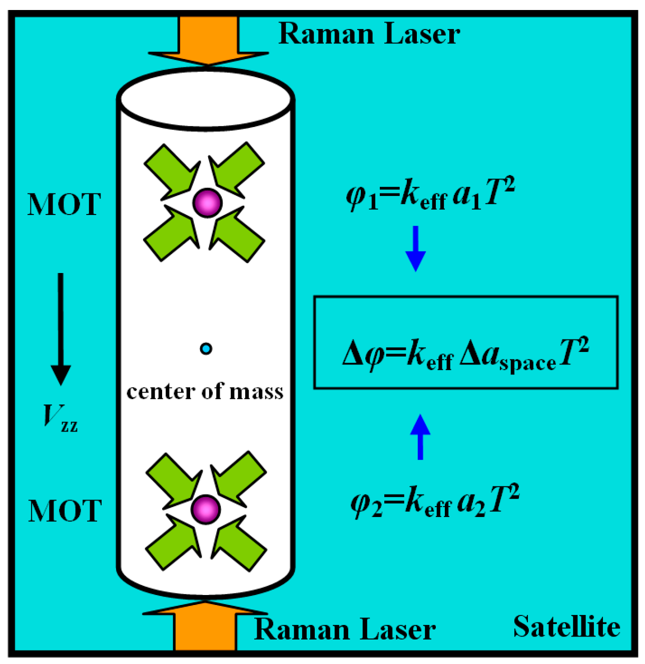
2. Principle of Atom-Interferometry Gravity Gradiometry in Space

SGG provides the second-order derivatives of the Earth’s gravitational potential V at the orbit height by carrying a spaceborne gravity gradiometer. The gradiometer consists of pairs of accelerometers. Based on the principle of differential accelerometry, the gradients of the gravitational accelerations can be obtained, which form a gravitational gradient tensor (GGT) with a 3 × 3 matrix as below [18]:
2 V r 2 = [   2 V X 2 2 V X Y 2 V X Z 2 V Y X 2 V Y 2 2 V Y Z 2 V Z X 2 V Z Y 2 V Z 2 ] = [ V xx   V xy V xz V yx   V yy V yz V zx   V zy V zz ] .
GOCE is the first mission to realize the concept of SGG in space. The core sensor electrostatic gravity gradiometer is placed at the satellite’s center of mass (CoM). It consists of three pairs of electrostatic accelerometers that are orthogonally mounted with a baseline of 50 cm and forms the gradiometer reference frame (GRF), as shown in Figure 1. Based on the electrostatic servo control for a test mass, the electrostatic accelerometer is used as an inertial sensor. The gravity gradients can be derived from the differential mode of the linear acceleration outputs of the gradiometer, where angular effects of the satellite also exist and must be removed [3].
Spaceborne atom-interferometry gravity gradiometer is fundamentally different from the previous mechanical sensor. It uses clouds of cold atoms as the test mass, which allows ultra-precise measurement in micro-gravity environments due to the longer interrogation time in space and shows a very low white noise spectral behavior. For inertial measurements with atom interferometry, 87 Rb, 85 Rb, and Cs atoms have been utilized, as there are cheap commercial diode lasers whose output frequencies are just near the resonant frequencies of the interest transition lines of these atoms. Compared to Rb atoms, Cs atoms have larger clock transitions, thus being appropriate to serve as a clock. In contrast, Rb atoms have a smaller collision shift and larger wave number, which makes them appropriate to serve for inertial measurements. Currently, 87 Rb atoms are most commonly used in inertial measurement by atom interferometry.
A gravity gradiometer is implemented with a pair of simultaneous atom-interferometer accelerometers. In an atom-interferometer accelerometer, a cloud of atoms is firstly collected and cooled in a Magneto-Optical Trap (MOT) by laser cooling and trapping techniques, and then the atoms are released from the MOT. Atom interferometry utilizes the wave nature of atoms to realize the interference of atom wavepackets. In analogy to optical interferometry, the atom wavepacket is firstly split, then reflected, and finally combined in an atom interferometer, and light pulses are usually explored to implement the above coherent manipulation of the atom wavepacket. During the interference process, a net phase shift φ is accumulated, which is related to the acceleration experienced by the atoms along the Raman laser direction of propagation. The output phase φ can be given by [19]:
φ = k eff a T 2 ,
where keff defines the effective wave vector of the Raman transition, T is the interrogation time between π/2 and π pulses, and a represents the accelerations sensed by the atom-interferometer accelerometer in GRF. For an atom-interferometer accelerometer pair in space, a can be written as:
{ a i , p = V ii l i / 2 + a i , ng , p a i , q = V ii ( l i / 2 ) + a i , ng , q ,
where ai,p and ai,q represent the accelerations sensed by the atom-interferometer accelerometer p and q along i direction (i = x, y, z) in GRF, Vii is the diagonal component of the GGT, li is the baseline separation of the atom-interferometer accelerometer pair along i direction, ai,ng,p and ai,ng,q represent the non-gravitational accelerations sensed by the atom-interferometer accelerometer p and q along i direction, which include external environment disturbances acting on satellite and the satellite angular effects, which are caused by the rotational angular velocity ω   of the satellite around its own axis, and include the centrifugal acceleration ω   × (   ω   ×   r   ) and Coriolis acceleration 2 ω × v , which will be discussed in detail in Section 3.
The gradiometer measures the gravitational acceleration difference through the differential phase output of the atom-interferometer accelerometer pair, as shown in Figure 2. In an atom-interferometry gravity gradiometer, the differential phase output can be given by:
Δ φ i = k eff ( a i , p a i , q ) T 2 = k eff ( V ii l i + Δ a i , ng ) T 2 ,
where Δ φ i represents the differential phase output of the atom-interferometer accelerometer pair along the i-axis, Δ a i , ng = a i , ng , p a i , ng , q is the differential non-gravitational acceleration, which mainly relies on the satellite angular effects in that most of the external environment disturbances (e.g., air drag, thruster firing) can be suppressed as common mode signals by differential accelerometry.
From the above, the diagonal gradient component Vii can be derived from the differential phase outputs of the atom-interferometry gravity gradiometer, where the non-gravitational accelerations, such as satellite angular effects, still exist and should be removed in the data processing.
It is noted that in order to improve the signal to noise ratio, the three diagonal components are usually used for gravity field recovery because the value of the diagonal elements is much larger than the off-diagonal elements. In addition, the trace of the gravity gradient tensor (the sum of the three diagonal components) is ideally zero, which can be used to evaluate the noise level of SGG. Thus, SGG mainly focuses on the measurement of the three diagonal elements. In our scheme, three diagonal elements can be measured with high precision, while the off-diagonal components cannot be measured due to the laser direction. However, in future work, other schemes could be designed to measure the off-diagonal components by changing the laser direction and gradiometer configuration.

3. SGG Mission Concept Based on Atom-Interferometry Gravity Gradiometry

This section firstly gives a feasible measurement concept for atom-interferometry SGG, which is quite different from on-ground measurement. Secondly, the measurement procedure, illustrations of the gradiometry set-up, and the linkages between the components are given. Thirdly, the determination of the key measurement parameters such as interrogation time are analyzed. These measurement parameters are very important and directly determine the final measurement noise of atom-interferometry SGG. Finally, the noise contribution to the atom-interferometry SGG is calculated.

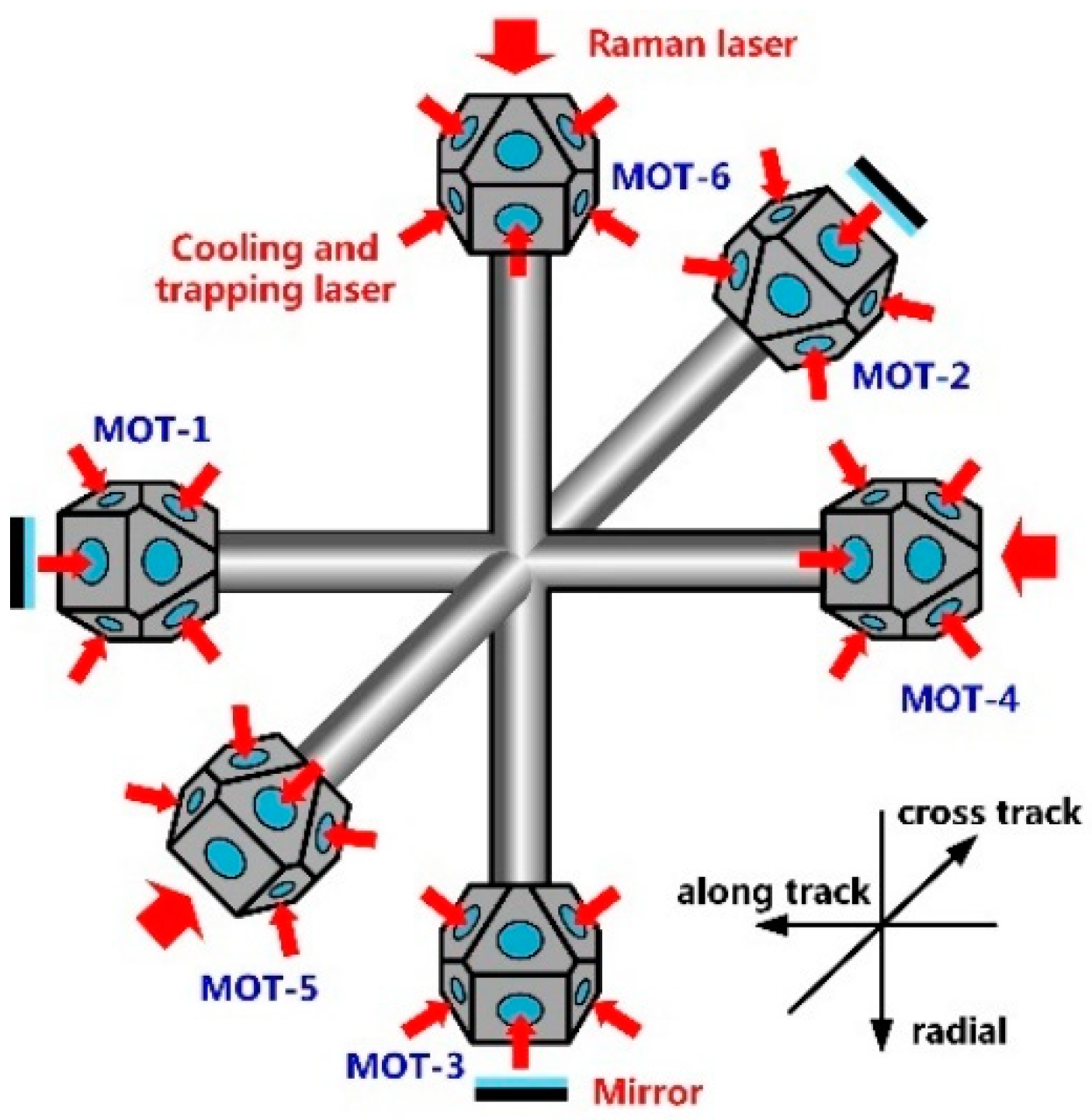
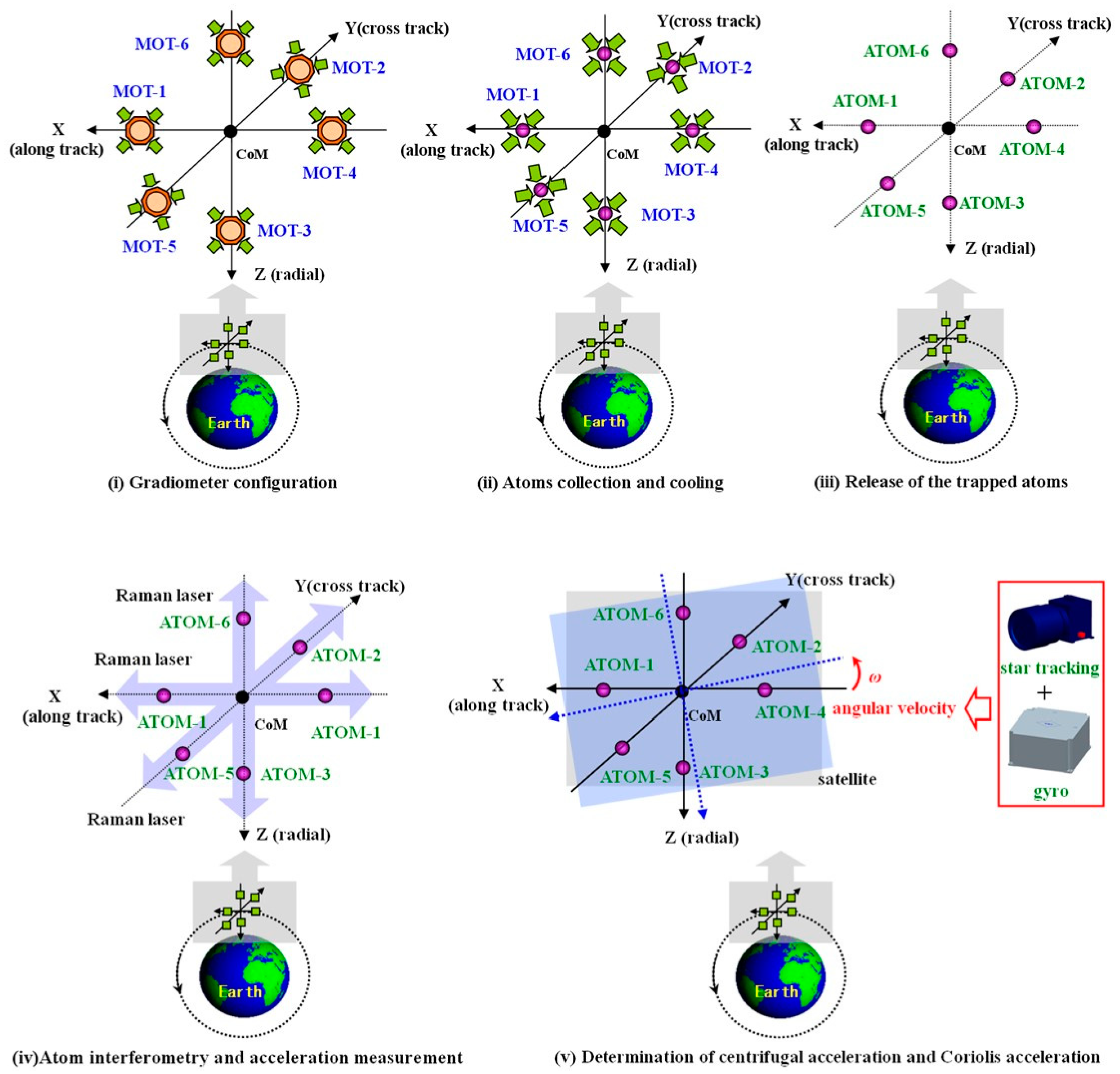
3.1. Measurement Concept for Spaceborne Atom-Interferometry Gravity Gradiometer

Atom interferometers are expected to achieve high sensitivity in gravity measurements from space, where the operation is quite different from that on the ground. Generally, in a ground-based measurement, the loaded cold atoms are launched vertically to form an “atomic fountain” and interference is implemented during the subsequent free fall of atoms. While in space, the cold atoms are flying as a drag-free test mass due to the micro-gravity environment, where the relative velocity between the atoms and the chamber (satellite) is nearly null [10]. In this case, no launch is necessary for the released atoms, allowing a much longer interrogation time in space. As a result, a viable technical implementation of the spaceborne atom-interferometry gravity gradiometer is shown in Figure 3, and the measurement procedure is given in Figure 4.
The atom-interferometry gravity gradiometer is placed at the satellite’s CoM. It consists of three orthogonally mounted one-axis gradiometers. Each of them constitutes two atom-interferometer accelerometers separated by a baseline of 50 cm. For each pair, the 87 Rb atom clouds are cooled and trapped in an MOT by the cooling and trapping laser, and then the Raman laser is emitted along the baseline direction and reflected back by the mirror to form counter-propagation laser beams centered on a non-uniform magnetic field. The trapped atoms are then released from the MOTs. The atoms are free flying as drag-free test masses in the frame of spacecraft, and the unitary velocity is null in ideal cases.
In each pair of accelerometers, the atom interferometry is realized simultaneously by using the same Raman laser beams so that common-mode noises can be effectively rejected in measuring the gravity gradient [14], such as Raman laser phase noise and vibration. In this case, the differential acceleration Δai in the micro-gravity environment can be given as [9].
Δ a i = V ii l i + Δ a rot , i ,
where Δarot,i defines the differential acceleration along the i direction induced by satellite rotational motion. For the measurement of diagonal gradient components, the satellite rotational part mainly contains centrifugal acceleration and Coriolis acceleration and should be removed in determination of the gravity gradients Vii [20], which are discussed in detail in Section 3.3.2.
From the above, the measurement expression for diagonal components of the GGT can be given by:
V ii = 1 l i ( Δ φ i k eff T 2 Δ a rot , i ) .

3.2. Optimization of Basic Parameters for Atom-Interferometry-Based SGG

Atom-interferometry gravity gradiometry with high precision is expected for future gradiometric missions. The sensitivity could be improved by optimizing the orbital parameters and interrogation time of atom interferometry, and these are discussed in detail as follows.

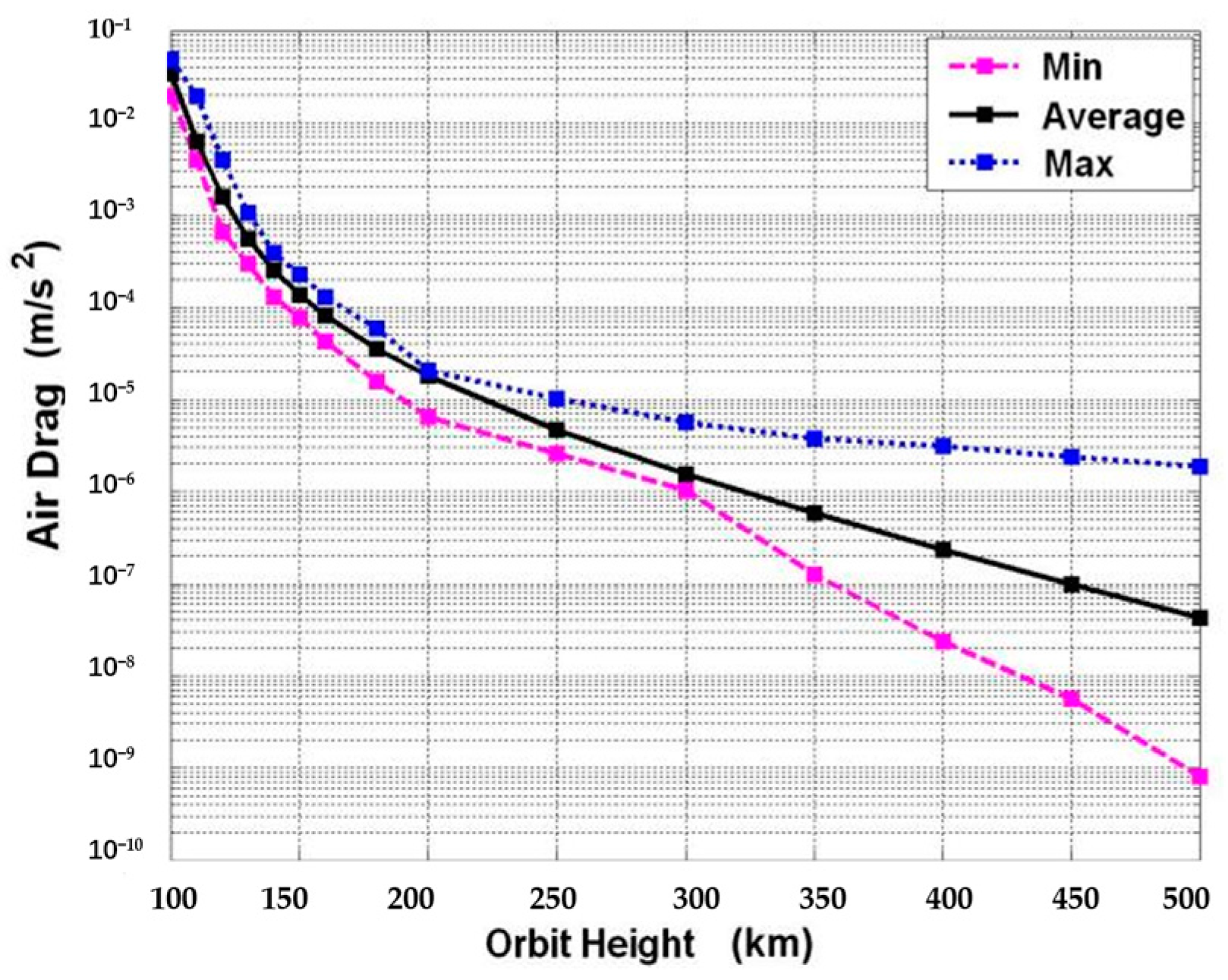
3.2.1. Optimization of Orbital Parameters

It is common practice that higher degrees of the gravitational field mapping could especially benefit from the reduced orbit altitude as the gravity field signal attenuates with increased altitude. This means the orbit altitude requires being as low as possible for future satellite gradiometric missions. Actually, the altitude determination is limited by the satellite’s capability for continuously counteracting the non-conservative accelerations at a low Earth orbit (LEO) so as to keep the satellite flying at a constant altitude and provide a suitable lifetime for the mission operating.
The non-conservative accelerations at LEO mainly come from the atmospheric drag in the flight direction. The acceleration disturbance adrag caused by the atmospheric drag can be formulated as a drag = F drag / m sc = C D ρ a p V R 2 / 2 m sc , where Fdrag is the atmospheric drag force, ρ is the local atmospheric density that varies with orbital altitude and period of the solar activity, CD = 2.2~2.6 is the coefficient of the atmospheric drag force, VR is the velocity vector of the incidence atmosphere stream, Ap is the area of the satellite’s cross section perpendicular to the atmosphere velocity vector. Models of the atmospheric density are employed to exhibit an atmospheric drag variance with orbital altitude, which provides a conservative estimation of the maximum atmospheric drag acceleration with a level of 10−6~10−5 m/s2 at LEO (altitude below 500 km), as shown in Figure 5. It would cause a rapid decrease in the orbit altitude.
Fortunately, the relatively high non-gravitational accelerations in the flight direction can be compensated by the active drag-free control, making use of ion and micro-thruster actuators, as applied in the GOCE gradiometry [21]. An area-mass ratio of Ap/msc = 0.001 is also used in the satellite design to minimize the atmospheric drag. This allows GOCE to operate at a nominal mean altitude of about 260 km from launch 2009 to mid-2012 [22], and the satellite orbit was lowered to 229 km in May 2013 in order to maximize the scientific return of the mission at the end of the mission lifetime. With the remaining fuel of the ion thruster, it was still possible to remain in drag-free mode for almost 6 months until the GOCE mission ended in November 2013 [23].
In this case, an orbital altitude of 229 km, which has been demonstrated in the GOCE mission, is suggested for the future atom-interferometry-based SGG, and an in-orbit scientific measurement duration of at least 6 months in drag-free mode at an altitude of 229 km could be achieved. An orbit eccentricity of 0.001 and an inclination of 96.5° are designed, which is consistent with GOCE. In addition, as the solar activity has an 11-year cycle [24], the satellite could be launched during the predicted time period from May 2029 to May 2031, when the solar cycle reaches its minimum. This would bring smaller external force disturbance and thus allow longer mission lifetime.

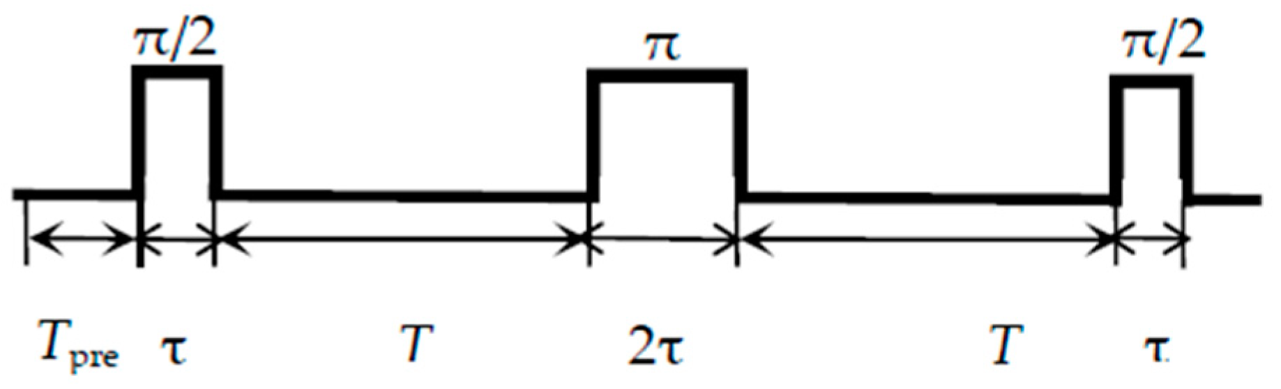
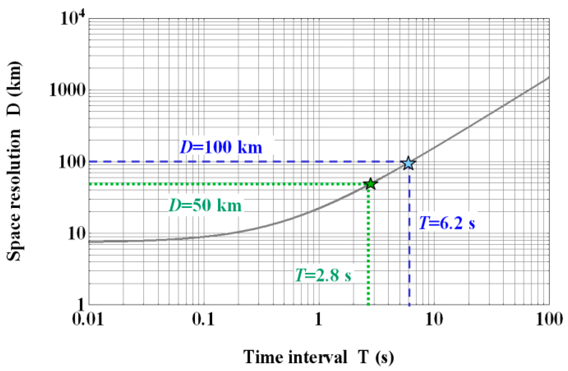
3.2.2. Optimization of Interrogation Time for Atom Interferometry

It is well known that the sensitivity of the atom-interferometry gravity gradiometer increases with the interrogation time T, which forms an interferometry time of about 2T for a single measurement (τ ≤ T). Before starting atom interferometry, it is possible to prepare the cold atoms in Tpre = 1 s [25], and then the total time to complete a single measurement of atom interferometry can be considered as Ttotal = 2T + Tpre, corresponding to a sampling rate fsam = 1/Ttotal for gravity gradiometry, as shown in Figure 6.
However, this presents a limitation on the determination of the spatial resolution of the gravity field model (half-wavelength) as follows:
D = π R L max = π R f max / f orbit = 2 π R ( 2 T + T pre ) f orbit ,
where D defines the spatial resolution of the gravity field model, R ≈ 6378 km represents the Earth’s mean radius, Lmax is the maximum degree of the expected spherical harmonic series expansion, forbit ≈ 1.87 × 10⁻⁴ Hz is the orbital frequency at an altitude of 229 km, and fmax = fsam/2 is the maximum frequency within which undistorted measurement signals can be obtained based on the Nyquist sampling theorem [26].
As defined before the launch, the objective of the GOCE mission was to resolve the Earth’s gravity field with a spatial resolution of 100 km [27]. It is obvious that the aim of future satellite gradiometric missions is to achieve better performance than GOCE in order to improve our knowledge in the field of earth science. Accordingly, a spatial resolution of 50~100 km is expected for the atom-interferometry-based SGG, which requires an interrogation time T from 2.8 s to 6.2 s, as shown in Figure 7. In this work, we select the interrogation time as a conservative value of T = 2.8 s, which corresponds to a total time of Ttotal = 6.6 s for a single measurement of atom interferometry and a sampling rate of fsam ≈ 0.15 Hz for SGG, and the resultant high frequency end of the gradiometer MBW can be determined as fmax = fsam/2 = 75 mHz.

3.3. Expected Sensitivity of the Spaceborne Atom-Interferometry Gravity Gradiometry

In this section, we analyze the potential sensitivity of the spaceborne atom-interferometry gravity gradiometry, as it dominantly affects the accuracy of the Earth’s gravity field recovery. The measurement error mainly comes from three parts: differential acceleration measurement, determination of the centrifugal acceleration and external disturbances, which are discussed below, respectively.

3.3.1. Differential Acceleration Measurement

Differential accelerometry by the atom-interferometer pairs is the key procedure of the atom-interferometry-based SGG. In order to enhance the sensitivity, Bose–Einstein Condensate (BEC) atoms at 10 nK can be used in our scheme to obtain a slow thermal expansion of 1 mm/s [9]. In this case, the entire expansion radius of the 87 Rb atom clouds would be no larger than 5.6 mm during an interferometry time of about 2 T = 5.6 s, which can be totally covered by a Raman beam diameter of 12~30 mm [28,29].
Differential acceleration of atomic clouds is detected based on simultaneous measurement of the phase shift φ, and the phase resolution is ultimately limited by quantum projection noise. For BEC atoms, the quantum projection noise with a Poissonian δφ = N−1/2 dependence would be traded for a reduction resulting from the N−1 dependence [30]. Thus, it gives an ultimate sensitivity to acceleration measurement as follows [8]:
δ a ( f ) = 1 C 1 N k eff T 2 T total ,
where keff = 1.6 × 10⁷ m−1 in 87Rb is the effective wave-vector of the Raman laser [10]. C defines the interferometer contrast, which is mainly influenced by the satellite’s rotation and gravity gradients [8]. Here, we choose a typical value of C = 0.6 under T ≈ 3 s by considering the impact of gravity gradients on contrast loss, and the effect of the satellite’s rotation is discussed in Section 3.3.2. N is the number of atoms for interference. Recent studies show that a BEC of N = 1 × 10⁵ 87Rb atoms can be produced at 1 Hz rate for mobile atom interferometers [31]. Conservatively, assuming 80% of the initial BEC atom number is left for interferometry after the state selection, it would in principle give a sensitivity of δa = 4.3 × 10⁻¹³ m/s2/Hz1/2 to acceleration measurement in the MBW. It corresponds to a sensitivity of δVii = δa/li = 1.2 mE/Hz1/2 for gradiometry under a baseline of li = 50 cm, where a term 2 is accounted for due to the uncorrelated noise of the two differential accelerometers. The result shows that it is at least three orders of magnitude better than the ground-based experiment of atomic fountains and one order of magnitude better than the in-orbit performance of the GOCE gradiometer.

3.3.2. Recovery of the Satellite Angular Effects

In the Earth center inertial (ECI) coordinate system, Newton’s second law is used for the atom cloud:
1 m F G = a o + a r + ω × ( ω × r ) + 2 ω × v
where FG represents the gravitational force from the Earth’s mass to atoms, m is the mass of the atoms, a o is the flight acceleration of the satellite centroid relative to ECI) coordinate system. a r is the acceleration of atoms relative to the satellite in the spacecraft body-fixed frame, which is also the output of the atom interferometers. ω × ( ω × r ) + 2 ω × v is the centrifugal and Coriolis accelerations in the spacecraft body-fixed frame, where ω represents the rotational angular velocity of a satellite around its own axis. v is the velocity of atoms relative to satellite in the body-fixed frame of the spacecraft.
The output of a pair of atom interferometers (defined as #1 and #2) along the same direction (single-axis gradiometer for example) can be written by
{ a r 1 = 1 m F G 1 a o [ ω × ( ω × r 1 ) + 2 ω × v 1 ] a r 2 = 1 m F G 2 a o [ ω × ( ω × r 2 ) + 2 ω × v 2 ]
Thus, the differential output (namely the output signal of the single-axis gradiometer) is
( a r 1 a r 2 ) L ^ L = 1 m ( F G 1 F G 2 ) L ^ L ( [ ω × ( ω × r 1 ) + 2 ω × v 1 ] [ ω × ( ω × r 2 ) + 2 ω × v 2 ] ) L ^ L
where L is the baseline length of the single-axis gradiometer, and L ^ determines the direction of the sensitive axis of the single-axis gradiometer. The first term in the right hand of the equation stands for the gravity gradient signal of the Earth that we intend to obtain. The second term stands for the influence induced by the satellite rotation, which is expected to be corrected in the measurement.
As the satellite carries out a rotational motion in space, the centrifugal acceleration ω × (ω × r) and Coriolis acceleration 2ω × v exist in the output of each atom-interferometer accelerometer, which can be expressed as follows:
a rot = ω × ( ω × r ) + 2 ω × V = ( ω y 2 ω z 2 ω x ω y ω x ω z ω x ω y ω x 2 ω z 2 ω y ω z ω x ω z ω y ω z ω x 2 ω y 2 ) ( r x r y r z ) + 2 ( 0 ω z ω y ω z 0 ω x ω y ω x 0 ) ( V x V y V z ) ,
where ω = [ωx, ωy, ωz] represents the satellite angular velocity, r = [rx, ry, rz] denotes the relative position of the atom clouds with respect to the satellite CoM, and v = [vx, vy, vz] is the residual velocity of the atom clouds relative to the satellite. These accelerations should be precisely measured and controlled in order to arrive at the gravity gradient components Vii and are discussed below.
The centrifugal acceleration measurement errors on diagonal components of the GGT can be written as:
δ V ii ( f ) = 2 ω j δ ω j ( f ) + 2 ω k δ ω k ( f ) ,
where δω is the measurement noise of the satellite angular velocity, and the subscript i, j and k (i = x, y, z; j = x, y, z; k = x, y, z) complete a right-handed triad. As the satellite attitude is Earth-pointing and the angular velocity around y-axis (nominal speed of ωy ≈ 1.17 × 10⁻³ rad/s) is much greater than that of the x-axis and z-axis, the centrifugal acceleration would produce the largest effect on the measurement of Vxx and Vzz. The dominant centrifugal terms around the y-axis can be recovered through an ultra sensitive gyroscope, which might give a high level of performance for satellite angular velocity measurements. The reported noise levels of the existing laser gyroscopes for rotation sensing have reached δωi = 2.2 × 10⁻¹⁰ rad/s/Hz1/2 although it is a little larger in size (1 m × 1 m) [32]. However, we can expect a more compact one for space application in the future. As a result, the recovery of the centrifugal acceleration contributes a noise of 0.5 mE/Hz1/2 to Vxx and Vzz measurement, and the noise of the Vyy component is much smaller than that of Vxx and Vzz. It is mentioned that the angular velocity will be finally reconstructed by combining the gyroscope measurements with the satellite attitude observations derived from the star sensor in lower frequencies [20].
The Coriolis acceleration due to the coupling of the satellite angular velocity ω with the relative velocity v between the atom clouds and the satellite is also inevitable and should be carefully considered and assessed. Fortunately, a tip-tilt mirror can be used in spaceborne atom interferometers to compensate the Coriolis acceleration [33], and the residual Coriolis acceleration after compensation will contribute to the gradiometry noise as follows:
δ V ii ( f ) = 2 l i [ ω j δ ( Δ V k ) + ω k δ ( Δ V j ) ] = 2 l i [ ω j 2 δ V k + ω k 2 δ V j ]   ,
where Δvi (i = x, y, z) is the differential velocity of the two atom clouds with respect to the satellite along the i direction, the factor stems from the differential effect between the two independent atom clouds, δvi (i = x, y, z) defines the residual velocity noise of each atom cloud in that the satellite velocity can be considered as common signal and is eliminated in differential measurement. As the angular acceleration can be reduced by approximately 60 times after Coriolis compensation [33], the large angular rate of 1.17 × 10⁻³ rad/s around the y axis would drop to the level of 2 × 10⁻⁵ rad/s. In this case, a velocity disturbance of δvx = δvz = 10 nm/s/Hz1/2 along the z and x directions is required in order to arrive at the expected noise level of 1.2 mE/Hz1/2 for Vxx and Vzz measurements, and the requirement for Vyy measurement could be much lower as the satellite angular rate around x and z axis gives a very small value. Fortunately, the linear velocity of the released atom cloud vi is nearly null because in our scheme, the atom clouds are drag-free in the frame of spacecraft after release. The residual velocities of the released atom clouds may result from the power imbalance of the six laser beams, which are used to cool and trap the atom clouds in the MOT. This means that the intensity of the six laser beams should be well controlled. The intensity radio of the laser beams can be defined as r = P2/P1 ≈ 1 + ΔP/P, where P1 ≈ P2 = P are the intensities of the two beams for a beam pair, ΔP = P2- P1 is the intensity difference between the beams. We assume a typical sensitivity to the drift velocities of 20 μm/s per % of r [34], and then an intensity difference of ΔP/P = 5 × 10⁻⁶/Hz1/2 for the laser beams is required, which is assumed achievable in other space science missions [35].

3.3.3. External Disturbances

It is well known that the atom interferometry is quite sensitive to the environmental fluctuations, mainly from the mechanical vibration and stray magnetic field [36]. Thus, the noise from environmental phase shifts has to be carefully analyzed to reach the desired sensitivity.
The mechanical vibration is considered common-mode perturbations in SGG. On the one hand, it is possible to suppress the mechanical vibrations by simultaneous differential measurements as the atom interferometer pair shares the same Raman laser beam in our scheme and thus has a common reference frame. With this configuration, an effective common-mode rejection of 140~155 dB could be expected [14,30,37]. In addition, the mechanical vibration might be further suppressed by using an active vibration isolator [38]. On the other hand, the mechanical vibration generated from spaceborne instruments and attitude control system themselves, should be kept as small as possible. For example, the laser gyroscope suggested in our scheme would produce almost no mechanical vibration on satellite, which is feasible for future spaceborne atom-interferometry gradiometry.
The magnetic field affects the sensitivity of atom-interferometry gravity gradiometry through second-order Zeeman shifts:
δ φ ( f ) = 2 · 2 π κ G ( f ) B δ B ( f )
where κ = 575 Hz / G 2 is the second-order Zeeman coefficient, and
G(f) = 2πT2f (f < 10 Hz)
is the sensitivity function of the Raman laser phase fluctuation [39], B and δB(f) are the magnetic field and its fluctuation at the atom interferometry region, respectively. In order to reduce the magnetic effect, the vacuum chamber is made of aluminum with a very low magnetic permeability, and the chamber is surrounded by a double layer of μ-metal shields to further prevent changes to the magnetic field in space [10,40]. Finally, the magnetic field would be uniform in time and in space within B = 0.3 mG along the atom interferometry region during the whole flight [10]. Experiments show that the magnetic fluctuation can be considered as δB(f) = B/100 in the MBW [41]. In this case, the magnetic field contributes a noise no larger than δVii = 0.7 mE/Hz1/2 to gravity gradient measurements below 0.1 Hz, which is acceptable for the atom-interferometry-based SGG.

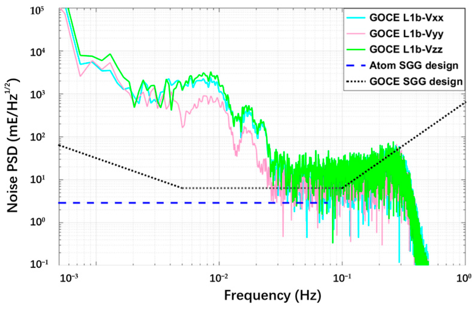
3.3.4. Summary of Noise Contribution

In our scheme, the three diagonal gradient components Vxx, Vyy and Vzz can be precisely measured by atom-interferometry-based SGG. Their measurement noise is affected by several factors that can be grouped into three main classes, as listed in Table 1.
The differential accelerometry noise is related to the performance of the instrument itself and mainly depends on the quantum projection noise, which gives a potential sensitivity of about 1.2 mE/Hz1/2, as discussed in Section 3.3.1. The noise of subtraction of the satellite angular effects concerns the satellite rotational motion, including both centrifugal acceleration and Coriolis acceleration. In our scheme, the centrifugal acceleration is mainly induced by the measurement noise of the satellite angular velocity δω from a laser gyroscope, which contributes a measurement noise of 0.5 mE/Hz1/2. The Coriolis acceleration mainly depends on the atom’s residual velocity noise δvi and requires a technique of Coriolis compensation and strict control of the intensity balance of the six beams in order to achieve the goal of 1.2 mE/Hz1/2, as analyzed in Section 3.3.2. The environmental disturbances, as discussed in Section 3.3.3, mainly come from the magnetic field and contribute a noise no larger than 0.7 mE/Hz1/2 through the technique of magnetic shielding. Thus, these three types of noise are independent and uncorrelated, and a noise power spectral density (PSD) of 1.9 mE/Hz1/2 is expected for the future Earth’s gravity field observation, as shown in Table 1.

3.4. Feasibility for Implementation of the Atom-Interferometry-Based SGG

The atom-interferometry gravity gradiometry is suggested for the future satellite gradiometric mission to achieve sensitive measurements for the diagonal gradient components Vxx, Vyy, Vzz, which would improve the accuracy of the Earth’s gravity field determination. However, it would inevitably bring some risks to the actual engineering application and mission implementation, which should be paid more attention and are discussed below.
First, as the atoms are uncontrolled after release and would be drag-free in the frame of the spacecraft, small relative acceleration between satellite and atom clouds would cause a deviation of the gradiometer’s center from the satellite CoM and an error on the gradiometer’s baseline length. The CoM offset is induced by the common-mode (CM) acceleration aCM, while the baseline length error results from the differential mode (DM) acceleration aDM. For the CM part, the center of the three gradiometer axes should proximately coincide with the satellite’s CoM. However, during a total time of Ttotal = 6.6 s for a single measurement of atom interferometry, the satellite’s CoM offset with respect to the gradiometer’s center would be accumulated up to Δd = aCM·Ttotal2/2 ≈ 33 μm. It is mainly caused by the residual linear acceleration acting on the satellite, which is no larger than aCM = 1.5 × 10⁻⁶ m/s2 [2] along the three gradiometer axes. Fortunately, it is acceptable in that SGG allows the CoM offset staying within 10 cm throughout the satellite’s lifetime [27]. Furthermore, the satellite should be designed with a highly symmetric configuration in order to minimize the uncertainties in the tank’s consumption. For the DM part, a length error of the gradiometer baseline between the two atom clouds would exist, which may result from gravity gradients and centrifugal accelerations, and can be considered as
Δli = aDM·Ttotal2/2 = [Vii + (ω2 − ωi2)]·Ttotal2/2
At an orbit altitude of 229 km, this would give a maximum error of about 90 μm on the baseline length, which can be precisely determined from the measurements of the differential accelerations and will be removed in data processing. Moreover, gravity gradients can also be precisely measured without knowledge of the relative position between the atomic clouds through shifting the frequency of the Raman lasers during the central π pulse, which has been suggested for Earth observation and geodesy [42].
Second, spaceborne atom-interferometry gravity gradiometry generally needs to take several seconds to complete a single measurement, which creates a much lower data sampling rate. This is different from the GOCE accelerometer and is ill-suited to precise satellite gravity measurements. In this case, high data-rate atom interferometers can be used, which allows efficient atom recapture and is able to reduce the dead time associated with preparing the cold atoms [43].
Finally, during the measurement, the atom clouds are in free fall while the Earth-pointing satellite takes a large rotational motion around the y axis. In this case, the relative position of the two atom clouds changes with respect to the laser measurement direction in the spacecraft reference frame. This would create misalignment and reduce the contrast of the atom interferometers. Fortunately, the Raman lasers can be rotated to track the atom clouds by rotating the retro-reflection mirrors and collimators [33]. This allows us not only to mitigate the misalignment effect but also to compensate for the Coriolis force, as discussed in Section 3.3.2.

3.5. Summary of the Measuring Characteristics and Requirements

From the above, a feasible method for atom-interferometry-based SGG is proposed towards future satellite gradiometric missions. Both instruments and the satellite performances have been optimized to achieve the expected noise of 1.9 mE/Hz1/2 for Vxx, Vyy and Vzz measurements in the MBW 1 mHz~75 mHz. The measuring characteristics and requirements for mission implementation are summarized in Table 2. The comparisons with respect to GOCE gradiometry are shown in Figure 8 and Table 3.
It is noted that Table 1 shows that the largest source of noise comes from the differential measurement noise and the Coriolis acceleration noise. The Coriolis acceleration noise is not a fundamental limitation for atom interferometry gravity gradiometry, which can be further reduced in the future through Coriolis compensation and strict control of the intensity balance of the laser beams. The Coriolis acceleration noise of 1.2 mE/Hz1/2 in our manuscript is just a maximum estimation. Actually, the dominant noise is the differential measurement noise, which mainly depends on the quantum projection noise. Fortunately, the quantum projection noise with a Poissonian δφ = N−1 dependence in our scheme presents white noise characteristics during the whole frequency bandwidth. Therefore, the noise is expected to have white characteristics, which is consistent with the characteristics of the atom interferometry gravity gradiometer: it does not suffer from drift but exhibits a very low and spectrally white noise [9], as compared with GOCE gradiometer. Thus, the noise PSD of atom SGG (blue dashed line) in Figure 8 is expected to be white down to the orbital frequency (~1.9 × 10⁻⁴ Hz) since all frequencies above the orbital frequency are important for gravity field retrieval.

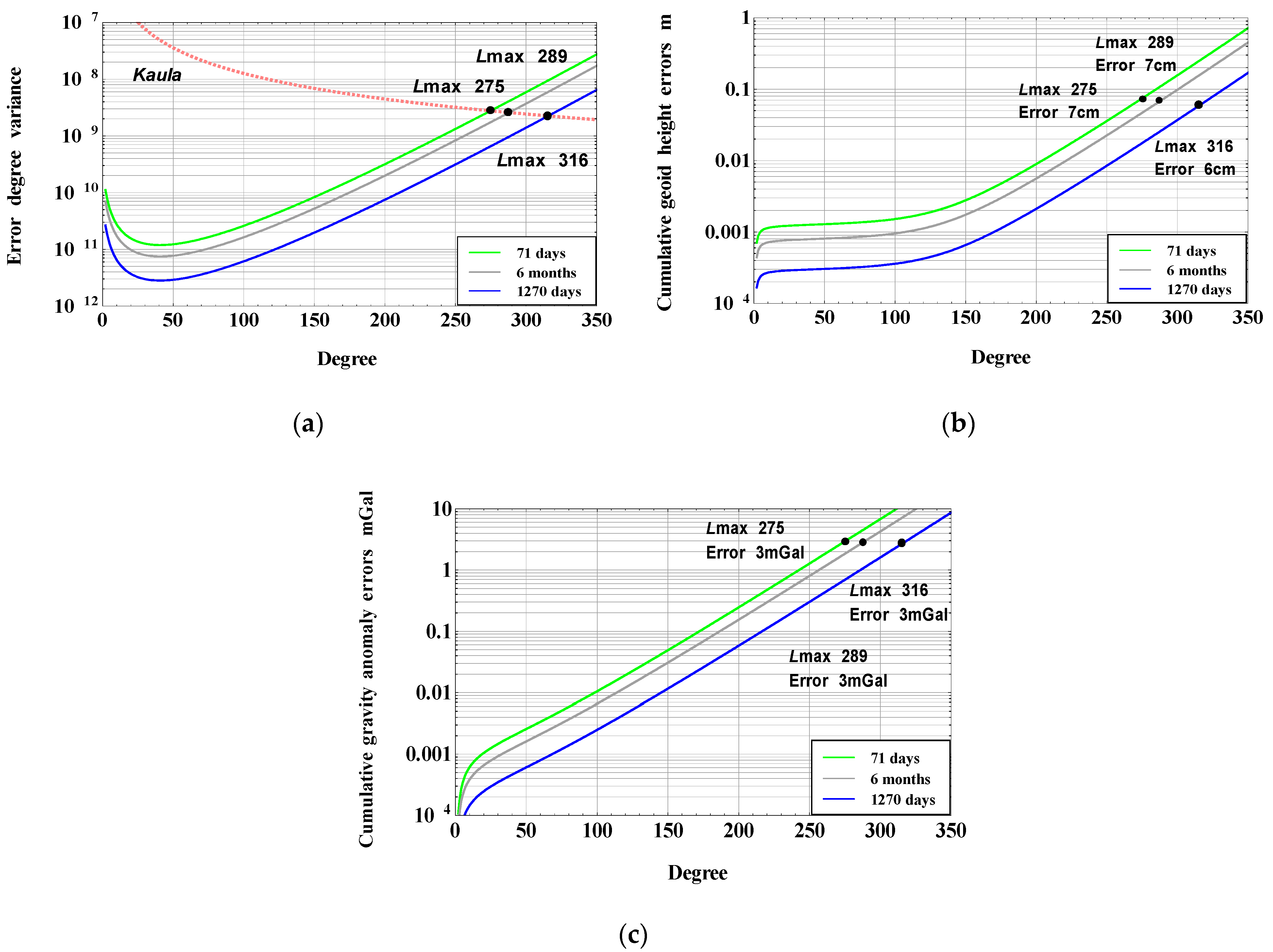
4. Improvements of the Earth’s Gravity Field Determination

This section gives the accuracy simulation of the gravity field recovery based on atom-interferometry SGG. The simulation method and parameters are discussed, and the reference model for comparison is introduced. Finally, the improved accuracy of gravity field recovery based on atom-interferometry SGG is given.
It is common practice to use the measured gradients Vxx, Vyy, Vzz as inputs for global gravity mapping in terms of spherical harmonics. Various gravity field models based on GOCE observations have been published. The accuracy of the released GOCE-only models is listed in Table 4. These pure GOCE models are derived from 71 days [44], 6 months [45] and 1270 days [46] of GOCE data, respectively. A recent study shows that all observations collected during the entire GOCE mission resolves the gravity field up to a maximum degree and order of 280 and provides a global model with a mean accuracy of 10 cm in terms of geoid height and 3.37 mGal in terms of gravity anomaly, respectively, at a spatial resolution of 80 km [46].
It is important to evaluate the accuracy of the gravity field modeling based on atom-interferometry SGG in order to simulate a potential improvement of the performance. The error estimation has been implemented through a directed-spectrum-analysis method [47]. For this method, a direct analytical expression between PSD of the satellite gravimetry measurements and spherical harmonic coefficients of the Earth’s gravity model is derived based on a two-dimensional Fourier description as follows
σ l = m = 0 l ( σ C ¯ l , m 2 + σ S ¯ l , m 2 ) = ( 2 l + 1 ) S zz ( f ) 1 T r GM R 3 ( l + 1 ) 2 ( l + 2 ) 2 ( R r ) 2 ( l + 3 )
where σ l is the error degree amplitudes (whose square is the error degree variances, denoted as σ l 2 ), R is the mean semi-major axis of the Earth, GM is the gravitational constant times mass of the Earth, r is the distance from the satellite’s centroid to the Earth’s center. l is the degree of spherical harmonic, Szz(f) is the noise PSD of SGG, and Tr is the data length of a time-series.
Accordingly, the cumulative geoid height errors and gravity anomaly errors can be written by
σ N = l = 0 R 2 σ l 2
and
σ Δ g = l = 0 [ GM R 2 ( l 1 ) ] 2 σ l 2
The above three expressions are applied in our simulation. The results, derived from the technique of atom-interferometry SGG only, are based on an orbit height of 229 km and a white noise PSD model of 1.9 mE/Hz1/2 for atom-interferometry SGG. Different data lengths are adopted in the simulation for comparison. It is noted that the deterministic error effects such as temporal aliasing from ocean tides and non-tidal atmospheric and oceanic mass variations are not dominant and have been neglected in our simulation because SGG aims at obtaining the high-order static gravity field through long-term observation data, and these effects have been averaged out over a long period of time.
The expected error degree variance of the spherical harmonic coefficients for atom-interferometry SGG is shown in Figure 9a. Indicated by the Kaula curve, the static gravity field can be resolved up to a maximum degree of Lmax = 275 and Lmax = 289 (corresponding to a spatial resolution of 73 km and 69 km half-wavelength), respectively, based on a data length of 71 days and 6 months. Moreover, the atom-interferometry SGG is able to map the Earth’s gravity field up to a maximum degree and order of Lmax = 316 (corresponding to a spatial resolution of 63 km half-wavelength) based on 1270 days of data.
Based on the error degree variance, the resulting cumulative geoid height errors and gravity anomaly errors have been computed, and the results are described in Figure 9b,c, respectively. It is shown that atom-interferometry SGG could resolve the Earth’s gravity field model with an accuracy of 7 cm in terms of geoid height and 3 mGal in terms of gravity anomaly at degree and order of Lmax = 275 based on a data length of 71 days. Furthermore, an accuracy of 7 cm in terms of geoid height and 3 mGal in terms of gravity anomaly at degree and order of Lmax = 289 can be achieved based on 6 months of data. In addition, the accuracy of the atom-interferometry-based model is estimated to be 6 cm in terms of geoid height and 3 mGal in terms of gravity anomaly at degree and order of Lmax = 316 based on 1270 days of data, assuming a longer lifetime for future gradiometric missions.
The comparison between GOCE-only models and atom-interferometry-based models is summarized in Table 4. Compared with GOCE solutions [44,45,46], which are shown in Table 4, the accuracy of the spherical harmonic coefficients determined by atom-interferometry-based SGG would be significantly improved. The cumulative geoid height errors and gravity anomaly errors at degree and order of 250 (corresponding to a spatial resolution of 80 km half-wavelength) are estimated to be 3.5 cm and 1.2 mGal, respectively, based on 71 days of atom-interferometry SGG data, and 6 months data collection is expected to give a global model with an accuracy of 2.1 cm in terms of geoid height and 0.8 mGal in terms of gravity anomaly, respectively, at a spatial resolution of 80 km. Furthermore, a better performance, namely 0.85 cm in terms of geoid height and 0.3 mGal in terms of gravity anomaly at a spatial resolution of 80 km, would be achievable based on a data length of 1270 days if a longer lifetime is allowed.

5. Conclusions

This paper presents a spaceborne measurement scheme for atom-interferometry gradiometry. This offers a possibility to realize precise gravity measurement by releasing the atoms without starting from an initial velocity, which makes the measurement more convenient and efficient. Lower orbital altitude and suitable interrogation time can bring a high sensitivity of 1.9 mE/Hz1/2 for Vxx, Vyy and Vzz measurement. Compared with GOCE, the proposed method gives a low and flat noise PSD to gravity gradient measurement and could significantly contribute to the improvement of the Earth’s static gravity field model. It would augment the spectral content of the gravity field in the degree and order of 280~316 and give an improved accuracy in geoid height and gravity anomaly. Our study may find important applications in geodesy and Earth observation in the future and benefit many areas of geophysics research. On the one hand, it is helpful for the study of solid earth; the data in Table 4 show that after a long period of 1270 days, a better performance, namely 0.3 mGal in terms of gravity anomaly at a spatial resolution of 80 km would be achievable, which is one order of magnitude higher than the 3.37 mGal gravity anomaly obtained from the GOCE model at the same spatial resolution. It can obtain finer crustal structure, more information on plate motion, and underground resources distribution. On the other hand, the global geoid can be refined. The data in Table 4 show that the gravity field model improved by our approach can achieve mm-level geoid at 80~100 km resolution, which is higher than the cm-level geoid obtained by GOCE at the same spatial resolution. Such a precise geoid could provide a more accurate global reference for precise measurements of continents, mountain peaks and rising sea levels due to global warming.
As pointed out, the proposed scheme currently illustrates the fundamental construction of an atom-interferometry gradiometric satellite to operate in space. It is premature, and some actual engineering issues are expected to be tackled for the mission implementation in the future. For example, tracking the atom clouds by rotating retro-reflection mirrors would cause a change in the measurement coordinates, which needs more complex data processing in gravity field recovery. In addition, in order to investigate the potential improvements over earth observation, we only focus on the major error and ultimate sensitivity limit for spaceborne atom-interferometry gradiometry, and the other technical noises [9], which can be well controlled and suppressed through various methods, are not discussed here, although they still require a careful assessment in order to arrive at the high sensitivity. In addition, miniaturization of the atom gradiometer apparatus is also essential for future space application [48].

Author Contributions

Conceptualization, Z.Z. and H.L.; methodology, Z.Z.; software, Z.Z.; validation, Z.Z., H.L., H.T., X.D. and Y.Z.; formal analysis, H.L.; investigation, Z.Z. and H.T.; resources, Z.Z. and X.D.; writing—original draft preparation, Z.Z.; writing—review and editing, H.L., H.T., X.D. and Y.Z. All authors have read and agreed to the published version of the manuscript.

Funding

This work is supported by the National Natural Science Foundation of China (Grants No.41974034 and No.41504034), National Key Research and Development Program of China (Grant No.2020YFC2200801 and No.2020YFC2200502).

Institutional Review Board Statement

Not applicable.

Informed Consent Statement

Not applicable.

Data Availability Statement

The GOCE L1b data are available at https://earth.esa.int/eogateway/missions/goce/data, accessed on 7 February 2022.

Acknowledgments

We kindly acknowledge the provision of GOCE L1b data from the ESA official website.

Conflicts of Interest

The authors declare no conflict of interest.

References

  1. Floberghagen, R.; Fehringer, M.; Lamarre, D.; Muzi, D.; Frommknecht, B.; Steiger, C.; Piñeiro, J.; da Costa, A. Mission design, operation and exploitation of the Gravity Field and Steady-state Ocean Circulation Explorer mission. J. Geod. 2011, 85, 749–758. [Google Scholar] [CrossRef]
  2. Zhu, Z.; Zhou, Z.B.; Cai, L.; Bai, Y.Z. Electrostatic gravity gradiometer design for the future mission. Adv. Space Res. 2013, 51, 2269–2276. [Google Scholar] [CrossRef]
  3. Rummel, R.; Yi, W.Y.; Stummer, C. GOCE gravitational gradiometry. J. Geod. 2011, 85, 777–790. [Google Scholar] [CrossRef]
  4. Drinkwater, M.R.; Haagmans, R.; Muzi, D.; Popescu, A. The GOCE mission: ESA’s first core Earth explorer. In Proceedings of the International GOCE User Workshop, Rome, Italy, 6–8 November 2006. [Google Scholar]
  5. Sorrentino, F.; Bodart, Q.; Cacciapuoti, L.; Lien, Y.H.; Prevedelli, M.; Rosi, G.; Salvi, L.; Tino, G.M. Sensitivity limits of a Raman atom interferometer as a gravity gradiometer. Phys. Rev. Appl. 2014, 89, 023607. [Google Scholar] [CrossRef] [Green Version]
  6. Wang, Y.P.; Zhong, J.Q.; Song, H.W.; Zhu, L.; Li, Y.M.; Chen, X.; Li, R.; Wang, J.; Mingsheng, Z. Location-dependent Raman transition in gravity-gradient measurements using dual atom interferometers. Phys. Rev. Appl. 2017, 95, 053612. [Google Scholar] [CrossRef]
  7. Silvestrin, P.; Aguirre, M.; Massotti, L.; Leone, B. The future of the satellite gravimetry after the GOCE mission. In Geodesy for Planet Earth; Kenyon, S., Ed.; Springer: Berlin/Heidelberg, Germany, 2012; pp. 223–230. [Google Scholar]
  8. Tino, G.M.; Sorrentino, F.; Aguilera, D.; Battelier, B.; Bertoldi, A.; Bodart, Q.; Bongs, K.; Bouyer, K.; Braxmaier, C.; Cacciapuoti, L.; et al. Precision Gravity Tests with Atom Interferometry in Space. Nucl. Phys. B 2013, 243–244, 203–217. [Google Scholar] [CrossRef] [Green Version]
  9. Carraz, O.; Siemes, C.; Massotti, L.; Haagmans, R. A spaceborne gravity gradiometer concept based on cold atom interferometers for measuring Earth’s gravity field. Microgravity Sci. Technol. 2014, 26, 139–145. [Google Scholar] [CrossRef] [Green Version]
  10. Sorrentino, F.; Bongs, K.; Bouyer, P.; Cacciapuoti, L. The space atom interferometer project: Status and prospects. J. Phys. 2011, 327, 012050. [Google Scholar] [CrossRef] [Green Version]
  11. Bidel, Y.; Carraz, O.; Charrière, R.; Cadoret, M.; Zahzam, N.; Bresson, A. Compact cold atom gravimeter for field applications. Appl. Phys. Lett. 2013, 102, 144107. [Google Scholar]
  12. Wu, X. Gravity Gradient Survey with a Mobile Atom Interferometer. Master’s Dissertation, Stanford University, Stanford, CA, USA, 2009. [Google Scholar]
  13. Sorrentino, F.; Bongs, K.; Bouyer, P.; Cacciapuoti, L.; Angelis, M.D.; Dittus, H.; Ertmer, W.; Giorgini, A.; Hartwig, J.; Hauth, M.; et al. A compact atom interferometer for future space missions. Microgravity Sci. Technol. 2010, 22, 551–561. [Google Scholar] [CrossRef] [Green Version]
  14. Yu, N.; Kogel, J.M.; Kellogg, J.R.; Maleki, L. Development of an atom-interferometer gravity gradiometer for gravity measurement from space. Appl Phys B 2006, 84, 647–652. [Google Scholar] [CrossRef]
  15. Könemann, T.; Brinkmann, W.; Göklü, E.; Lämmerzahl, C.; Dittus, H.; van Zoest, T.; Rasel, E.M.; Ertmer, W.; Lewoczko-Adamczyk, W.; Schiemangk, M.; et al. A freely falling magneto-optical trap drop tower experiment. Appl. Phys. B 2007, 89, 431–438. [Google Scholar] [CrossRef]
  16. Müntinga, H.; Ahlers, H.; Krutzik, M.; Wenzlawski, A.; Arnold, S.; Becker, D.; Bongs, K.; Dittus, H.; Duncker, H.; Gaaloul, N.; et al. Interferometry with Bose-Einstein condensates in microgravity. Phys. Rev. Lett. 2013, 110, 093602. [Google Scholar] [CrossRef] [PubMed] [Green Version]
  17. Geiger, R.; Ménoret, V.; Stern, G.; Zahzam, N.; Cheinet, P.; Battelier, B.; Villing, A.; Moron, F.; Lours, M.; Bidel, Y.; et al. Detecting inertial effects with airborne matter-wave interferometry. Nat. Commun. 2011, 2, 474. [Google Scholar] [CrossRef] [PubMed] [Green Version]
  18. Rummel, R.; Balmino, G.; Johannessen, J.; Visser, P.N.A.M.; Woodworth, P. Dedicated gravity field missions—Principles and aims. J. Geodyn. 2002, 33, 3–20. [Google Scholar] [CrossRef]
  19. Kasevich, M.; Chu, S. Measurement of the gravitational acceleration of an atom with a light pulse atom interferometer. Appl. Phys. B 1992, 54, 321–332. [Google Scholar] [CrossRef]
  20. Stummer, C.; Fecher, T.; Pail, R. Alternative method for angular rate determination within the GOCE gradiometer processing. J. Geod. 2011, 85, 585–596. [Google Scholar] [CrossRef]
  21. Canuto, E.; Molano, A.; Massotti, L. Drag-free control of the GOCE satellite: Noise and observer design. IEEE Trans. Control Syst. Technol. 2010, 18, 501–509. [Google Scholar] [CrossRef] [Green Version]
  22. Sechi, G.; Buonocore, M.; Cometto, F.; Saponara, M.; Tramutola, A.; Vinai, B. In-ight results from the drag-free and attitude control of GOCE satellite. In Proceedings of the 18th International Federation of Automatic Control (IFAC) World Congress, Milano, Italy, 28 August–2 September 2011; pp. 733–740. [Google Scholar]
  23. Steiger, C.; Romanazzo, M.; Emanuelli, P.P.; Floberghagen, R. Flying at the edge-extremely low altitude operations for ESA’s drag-free gravity mission GOCE. In Proceedings of the AIAA Guidance, Navigation and Control Conference, Boston, MA, USA, 19–22 August 2013. [Google Scholar]
  24. Willson, R.C.; Gulkis, S.; Janssen, M.; Hudson, H.S.; Chapamn, G.A. Observations of Solar irradiance variability. Science 1981, 211, 700–702. [Google Scholar] [CrossRef]
  25. Zoest, T.V.; Gaaloul, N.; Singh, Y. Bose-Einstein Condensation in Microgravity. Science 2010, 328, 1540–1543. [Google Scholar] [CrossRef] [Green Version]
  26. Landau, H.J. Sampling, data transmission, and the Nyquist rate. Proc. IEEE 1967, 55, 1701–1706. [Google Scholar] [CrossRef]
  27. ESA. The Four Candidate Earth Explorer Core Missions-Gravity Field and Steady-State Ocean Circulation Mission; ESA SP-1233(1); ESA Publications Division: Noordwijk, The Netherlands, 1999. [Google Scholar]
  28. Barrett, B.; Gominet, P.A.; Cantin, E.; Antoni-Micollier, L.; Landragin, A. Mobile and remote inertial sensing with atom interferometers. In Proceedings of the International School of Physics “Enrico Fermi”: Atom interferometry, Varena, Italy, 1–6 July 2013; pp. 493–555. [Google Scholar]
  29. Canuel, B.; Leduc, F.; Holleville, D.; Gauguet, A.; Fils, J.; Virdis, A.; Clairon, A.; Dimarcq, N.; Borde, J.; Bouyer, P.; et al. 6-axis inertial sensor using cold-atom interferometry. Phys. Rev Lett. 2006, 97, 010402. [Google Scholar] [CrossRef] [PubMed] [Green Version]
  30. Maleki, L.; Yu, N.; Kohel, J. Quantum gravity gradiometer for sub-surface imaging. In Proceedings of the Space 2004 Conference and Exhibit, AIAA, San Diego, CA, USA, 28–30 September 2004; p. 5906. [Google Scholar]
  31. Rudolph, J.; Herr, W.; Grzeschik, C.; Sternke, T.; Grote, A.; Popp, M.; Becker, D.; Müntinga, H.; Ahlers, H.; Peters, A.; et al. A high-flux BEC source for mobile atom interferometers. New J. Phys. 2015, 17, 065001. [Google Scholar] [CrossRef] [Green Version]
  32. Stedman, G.E.; Schreiber, K.U.; Bilger, H.R. On the detectability of the Lense-Thirring field from rotating laboratory masses using ring laser gyroscope interferometers. Cl. Quantum Grav. 2003, 20, 2527–2540. [Google Scholar] [CrossRef]
  33. Lan, S.Y.; Kuan, P.C.; Estey, B.; Haslinger, P.; Mller, H. Influence of the Coriolis Force in Atom Interferometry. Phys. Rev. Lett. 2012, 108, 090402. [Google Scholar] [CrossRef] [Green Version]
  34. Louchet-Chauvet, A.; Farah, T.; Bodart, Q.; Clairon, A.; Landragin, A.; Merlet, S. The influence of transverse motion within an atomic gravimeter. New J. Phys. 2011, 13, 065025. [Google Scholar] [CrossRef] [Green Version]
  35. Jennrich, O.; Heinzel, G. Laser Requirements for a Gravitational Wave Mission, Version 0.1. 2013. Available online: https://asd.gsfc.nasa.gov/Jordan.Camp/eLISA_laser_reqs.pdf (accessed on 7 February 2022).
  36. Coq, Y.; Retter, J.A.; Richard, S.; Aspect, A.; Bouyer, P. Coherent matter wave inertial sensors for precision measurements in space. Adv. Space Res. 2012, 49, 365–372. [Google Scholar] [CrossRef] [Green Version]
  37. Yu, N.; Kogel, J.M.; Romans, L.; Maleki, L. Quantum gravity gradiometer sensor for Earth science applications. In Proceedings of the NASA Earth Science and Technology Conference 2002, Pasadena, CA, USA, 11–13 July 2003; p. B3P5. [Google Scholar]
  38. Zhou, M.K.; Hu, Z.K.; Duan, X.C.; Sun, B.L.; Chen, L.L.; Zhang, Q.Z. Performance of a cold-atom gravimeter with an active vibration isolator. Phys. Rev. A. 2012, 86, 043630. [Google Scholar] [CrossRef]
  39. Cheinet, P.; Canuel, B.; Santos, F.P.D.; Gauguet, A.; Yver-Leduc, F.; Landragin, A. Measurement of the sensitivity function in time-domain atomic interferometer. IEEE Trans. Instrum. Meas. 2008, 57, 1141–1148. [Google Scholar] [CrossRef] [Green Version]
  40. Stern, G.; Battelier, B.; Geiger, R.; Varoquaux, G.; Villing, A.; Moron, F.; Carraz, O.; Zahzam, N.; Bidel, Y.; Chaibi, W.; et al. Light-pulse atom interferometry in microgravity. Eur. Phys. J. D 2008, 53, 353–357. [Google Scholar] [CrossRef] [Green Version]
  41. Duan, X.C. Principle Experiment of Measuring Gravity Gradient by Atom Interferometry. Master’s Dissertation, Huazhong University of Science and Technology, Wuhan, China, 2011. [Google Scholar]
  42. D’Amico, G.; Rosi, G.; Zhan, S.; Cacciapuoti, L.; Fattori, M.; Tino, G.M. Canceling the Gravity Gradient Phase Shift in Atom Interferometry. Phys. Rev. Lett. 2017, 119, 253201. [Google Scholar] [CrossRef] [PubMed] [Green Version]
  43. McGuinness, H.J.; Rakholia, A.V.; Biedermann, G.W. High data-rate atom interferometer for measuring acceleration. Appl. Phys. Lett. 2012, 100, 011106. [Google Scholar] [CrossRef] [Green Version]
  44. Pail, R.; Bruinsma, S.; Migliaccio, F.; Förste, C.; Goiginger, H.; Schuh, W.D. First GOCE gravity field models derived by three different approaches. J. Geod. 2011, 85, 819–843. [Google Scholar] [CrossRef] [Green Version]
  45. Pail, R.; Goiginger, H.; Schuh, W.; Höck, E.; Brockmann, J.M.; Fecher, T.; Mayrhofer, R.; Krasbutter, I.; Mayer-Gürr, T. GOCE-only gravity field model derived from 8 months of GOCE data. In Proceedings of the 4th International GOCE User Workshop, Munich, Germany, 31 March–1 April 2011; p. SP-696. [Google Scholar]
  46. Brockmann, J.M.; Zehentner, N.; Höck, E.; Pail, R.; Loth, I.; Mayer-Gurr, T.; Schuh, W.-D. EGM_TIM_RL05: An independent geoid with centimeter accuracy purely based on the GOCE mission. Geophys. Res. Lett. 2014, 41, 8089–8099. [Google Scholar] [CrossRef]
  47. Cai, L.; Zhou, Z.; Xu, H.; Gao, F.; Zhu, Z.; Luo, J. Analytical error analysis for satellite gravity field determination based on two-dimensional Fourier method. J. Geod. 2013, 87, 417–426. [Google Scholar] [CrossRef] [Green Version]
  48. Rakholia, A.; Sugarbaker, A.; Black, A.; Kasevich, M.; Saif, B.; Luthcke, S.; Callahan, L.; Seery, B.D.; Lee, F.; Mather, J.C.; et al. Development of an atom interferometer gravity gradiometer for earth sciences. In Proceedings of the 48th Annual Meeting of the APS Division of Atomic, Molecular and Optical Physics, Sacramento, CA, USA, 5–9 June 2017; Volume 62, p. K1.00010. [Google Scholar]
Figure 1. Principle of satellite gravity gradiometry.
Aerospace 09 00253 g001
Figure 2. Operational principle of atom-interferometry gravity gradiometry in space.
Aerospace 09 00253 g002
Figure 3. Spaceborne atom-interferometry gravity gradiometry set-up concept.
Aerospace 09 00253 g003
Figure 4. Procedure of technical implementation of the spaceborne atom-interferometry gravity gradiometer.
Aerospace 09 00253 g004
Figure 5. Atmospheric drag variance with different orbital altitudes in the flight direction.
Aerospace 09 00253 g005
Figure 6. Time sequence for a single measurement of the atom interferometry.
Aerospace 09 00253 g006
Figure 7. Limitation on spatial resolution of the Earth’s gravity field caused by interrogation time of atom interferometry.
Aerospace 09 00253 g007
Figure 8. Noise PSD of diagonal components of the GGT for different SGG. The expected noise level of atom-interferometry-based SGG is described as a dashed line. The prelaunch design and in-orbit performance of the GOCE SGG are also shown by dotted and solid lines, respectively, for comparison. The in-orbit results of Vxx, Vyy and Vzz are relevant to one orbit of GOCE L1b data from the ESA official website (00:49:15–02:18:59, 1 November 2009, data length: 5384 s).
Aerospace 09 00253 g008
Figure 9. Expected (a) error degree variance, (b) cumulative geoid height errors and (c) cumulative gravity anomaly errors of the Earth’s gravity field mapping by atom-interferometry SGG. The results shown by the green and gray curves are based on a data length of 71 days and 6 months, respectively, while the blue curves represent performance predictions based on data length of 1270 days assuming a longer lifetime for future atom-interferometry gravity gradiometric mission.
Aerospace 09 00253 g009
Table 1. Noise contribution to atom-interferometry-based SGG.
Noise SourceNoise Contribution
Differential acceleration measurement1.2 mE/Hz1/2
Centrifugal acceleration0.5 mE/Hz1/2
Coriolis acceleration1.2 mE/Hz1/2
External disturbances0.7 mE/Hz1/2
Total1.9 mE/Hz1/2
Table 2. Measuring characteristics and requirements for mission implementation.
SourceMeasuring Characteristics and Requirements
OrbitMean altitude: 229 km
Eccentricity: 0.001
Inclination: 96.5°
Measurement duration: ≥6 months
Satellite operating mode: drag-free mode
Suggested launch time: May 2029~May 2031
Satellite attitudeAttitude pointing mode: Earth-pointing
Angular velocity: ωy ≈ 1.17 × 10⁻³ rad/s, ωx ≈ ωz ≈ 6 × 10⁻⁵ rad/s
Different acceleration measurementMeasurement bandwidth: 0~75 mHz
Interrogation time T: 2.8 s
BEC atoms preparation: 105 atoms at 1 Hz rate
Sampling rate: 0.15 Hz
Baseline separation: 50 cm
Ultimate sensitivity: 4 × 10⁻¹³ m/s2/Hz1/2
Recovery of satellite angular effectsGyro resolution: 2.2 × 10⁻¹⁰ rad/s/Hz1/2
Coriolis compensation factor: abefore/aafter = 60
Relative velocity disturbance requirement: 10 nm/s/Hz1/2
Laser intensity difference requirement: 5 × 10⁻⁶/Hz1/2
External disturbancesVibration suppression: 140~155 dB
Magnetic field B: 0.3 mG
Magnetic fluctuation δB: B/100
Table 3. Comparison between GOCE gradiometry and atom-interferometry gradiometry.
GOCE GradiometryAtom-Interferometry
Gradiometry
Operational principleElectrostatic servo-control
(Newtonian mechanics)
Atom interferometry
(Quantum mechanics)
Test massPtRh1087Rb atoms
Gradient components to be measuredDiagonal components Vxx, Vyy, Vzz
Non-diagonal components Vxz, Vyz, Vxy
Diagonal components Vxx, Vyy, Vzz
Table 4. Error estimation of the Earth’s gravity field model derived by atom-interferometry SGG and comparison with released GOCE-only models.
Data LengthData SourceMaximum Degree and
Order
Cumulative Geoid Height ErrorsCumulative Gravity Anomaly Errors
71 daysGOCE22410 cm@100 km3 mGal@100 km
71 daysAtom SGG2750.9 cm@100 km
3.5 cm@80 km
0.24 mGal@100 km
1.2 mGal@80 km
6 monthsGOCE2506 cm@100 km
10 cm@80 km
1.8 mGal@100 km
3.4 mGal@80 km
6 monthsAtom SGG2890.55 cm@100 km
2.1 cm@80 km
0.16 mGal@100 km
0.8 mGal@80 km
1270 daysGOCE2802.4 cm@100 km
10 cm@80 km
0.7 mGal@100 km
3.37 mGal@80 km
1270 daysAtom SGG3160.2 cm@100 km
0.85 cm@80 km
0.06 mGal@100 km
0.3 mGal@80 km
Publisher’s Note: MDPI stays neutral with regard to jurisdictional claims in published maps and institutional affiliations.

