Article

Bionic Design Method of a Non-Uniform Lattice Structure for a Landing Footpad

1
School of Mechanical Engineering and Automation, Beihang University, Beijing 100191, China
2
State Key Laboratory of Virtual Reality and Systems, Beihang University, Beijing 100191, China
*
Author to whom correspondence should be addressed.
Aerospace 2022, 9(4), 220; https://doi.org/10.3390/aerospace9040220
Submission received: 12 March 2022 / Revised: 11 April 2022 / Accepted: 13 April 2022 / Published: 15 April 2022

Abstract

:
Due to its excellent performance and high design freedom, the lattice structure has shown excellent capabilities and considerable potential in aerospace and other fields. Inspired by the bamboo structure, a lattice cell configuration namely BCC4IZ is designed and a lattice alternative layout is obtained. Then, a design and modeling method for non-uniform lattice structures is proposed. Four designs of the landing footpad with different kinds of lattice cells are developed. A series of dynamic explicit finite element simulations were conducted to evaluate and compare the energy absorption and capacity of resisting impact deformation performance of different designs. The results show that the combination of the bionic design and the lattice structure can effectively improve the performance of the lattice-filled footpad. This study proves the feasibility and potential of application for bionic design in lattice structure.

1. Introduction

Because of their excellent mechanical properties and multifunctionality, lattice structures have received widespread attention in both academia and industry. The lattice structures have a variety of topological configurations, and each unit can be defined by different parameters, thus demonstrating a higher designability than the conventional metal foams [1].
Since the concept of lattice structure was put forward, its mechanical properties, especially the energy absorption, have been widely studied. Typical lattice cell configurations such as BCC (DIAG) [2,3,4,5,6,7], OCTET [8,9,10], and SC [7,11,12,13,14], have received a lot of research including analysis, modeling, and experimental methods. Compared with 1D and 2D [15,16,17], a 3D periodic lattice structure can exhibit anisotropic macro characteristics to meet more complex design requirements—however, also making its design more complex [18,19]. Deshpande et al. [8] analyzed the mechanical properties of octet lattice cell structure and established a mechanical model for the octet lattice cell. Ushijima et al. [20] developed a prediction model to analyze the stiffness and strength of the bending dominated BCC cell lattice structure. However, predictive models are usually only available for lattice structures composed of periodic unit cells. For varying lattice configurations and non-uniform lattice structures, the finite element analysis method is a common alternative. Many studies employ solid elements to discrete the lattice structure. While solid elements are versatile for structural analysis, they often result in large-scale finite element models for lattice structures. In order to improve the efficiency of the finite element analysis, scholars also studied the simplified or equivalent modeling approaches. Smith et al. [21] employed the beam elements to model the rods in the lattice cells and improved the accuracy by increasing the diameter of the beam elements at the joint of the cells. Liu et al. [5] established a theoretical model and a finite element model of the multilayer BCC lattice structure and compared the theoretical and finite element analysis results with the experimental results.
Compared with standard and uniform lattice structures, studies on lattice cell structures with non-uniform configurations are relatively few. However, the microstructures in polycrystal and animal bones are generally non-uniform and they also provide a rich reference for the design of lattice cells. Pham et al. [22] studied microstructure of polycrystalline metals and introduced grain boundary hardening, precipitate strengthening, and multiphase strengthening into the design of the lattice structure. The results show that the lattice structure with the above strengthening method exhibits a mechanical behavior similar to that of alloy crystals, thereby strengthening the overall performance of the lattice structure. Bian and Li et al. [23,24,25] designed a series of polycrystal-inspired lattice structures by studying the structural form of polycrystals and. Yang et al. [26] proposed a lattice cell configuration by topology optimization method. The design result is very similar to the structure of cuttlebone and shows excellent compression-resistant and energy absorption capability. Fernandes et al. [27] and Sharma et al. [28] studied the lattice structure for energy absorption with eupletella aspergillum as the bionic object, The design results demonstrate excellent performance in terms of both the structural robustness and energy absorption.
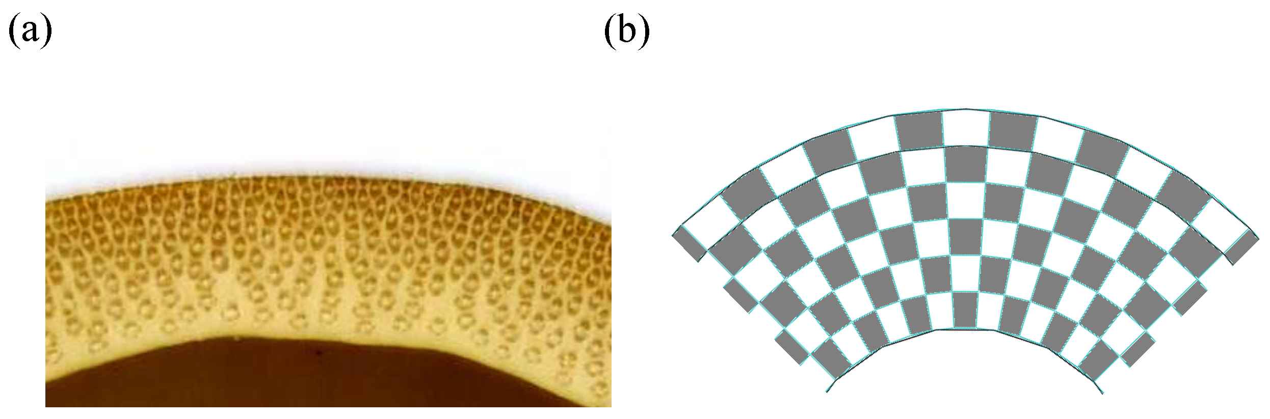
Besides, the microstructure of bamboo and its spatial distribution has also been taken as bionic design references [29,30,31,32]. Ray et al. [33] stated that bamboo is one of the best functionally gradient composite materials available and studied the correlation between vascular bundle microstructure and mechanical strength. Sato et al. [34] determined the optimal stiffness design for fiber-reinforced cylindrical composites, which is very similar to the wild bamboos. Fu et al. [35] proposed a bionic-bamboo tube (BBT) structure, which is inspired by both the structural form of vascular bundle and the simple circumferential distribution law. The results show that the energy absorption capacity of BBT structure is significantly higher than that of the initial design. Xu et al. [36] employ the vascular bundle microstructure of bamboo as the design reference to improve the crashworthiness design of bumper.
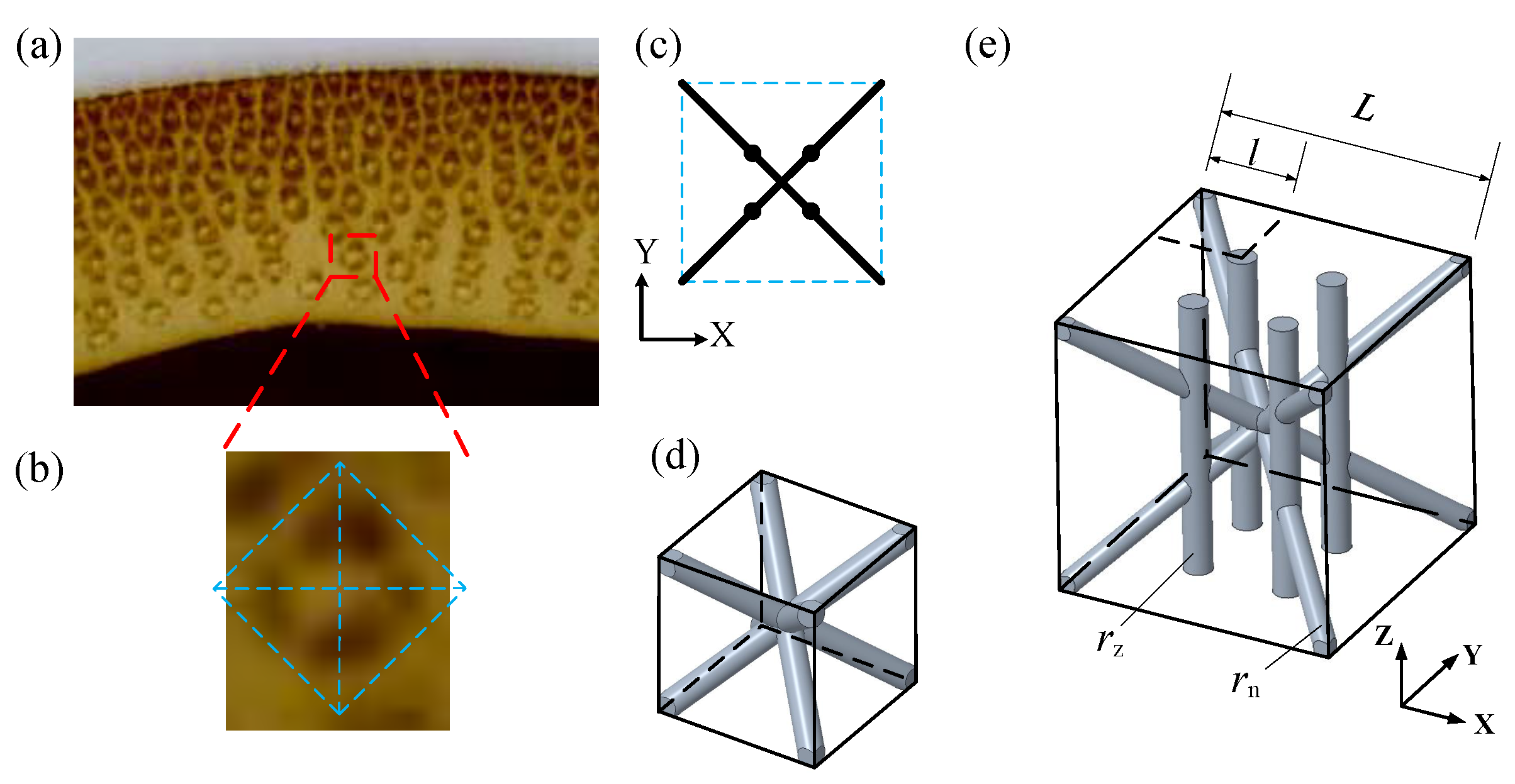
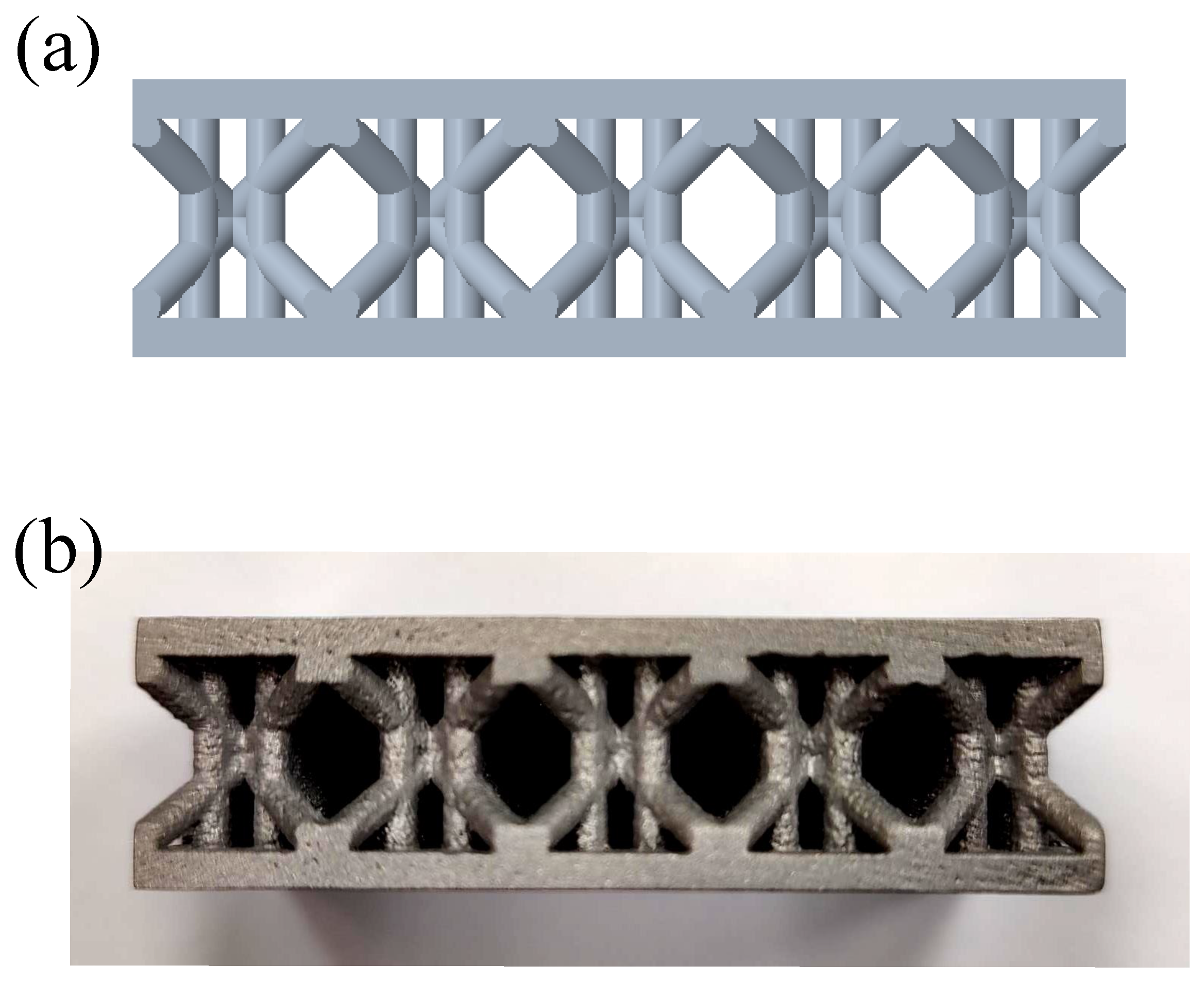
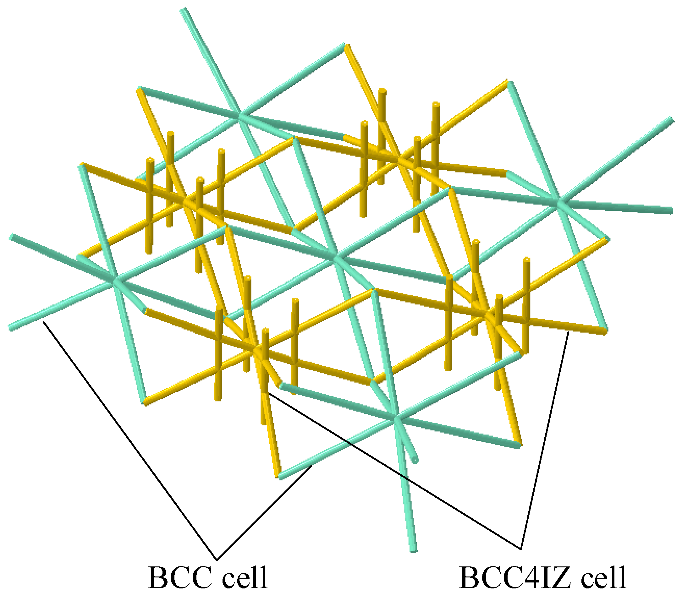
The landing footpad is a critical component of the lunar lander, whose performance is crucial to a successful landing. Its main function is to resist impact deformation while absorbing impact energy. In this study, the design goal is to improve the footpad’s ability to resist impact deformation while preserving its capability of energy absorption. Bamboo, characterized by its vascular bundle structure, inspires this bionic design. A novel lattice cell configuration, namely the BCC4IZ, is proposed, based on which one bionic design for landing footpads is developed. Then, the layout of the vascular bundle structure in the bamboo cross-section is also taken as the bionic design object. Combined with the proposed lattice cell configuration, another bionic design for the landing footpad is also developed. The above two biomimetic designs are compared with the traditional lattice cell configuration. The results demonstrated that the bionic designs can increase the capacity of the footpad for resisting impact deformation without reducing the energy-absorbing performance, which also verify the rationality of the biomimetic design method.
The layout of this paper is organized as follows: Section 2 introduces the bamboo-inspired bionic lattice cell configuration and lattice alternative layout. 
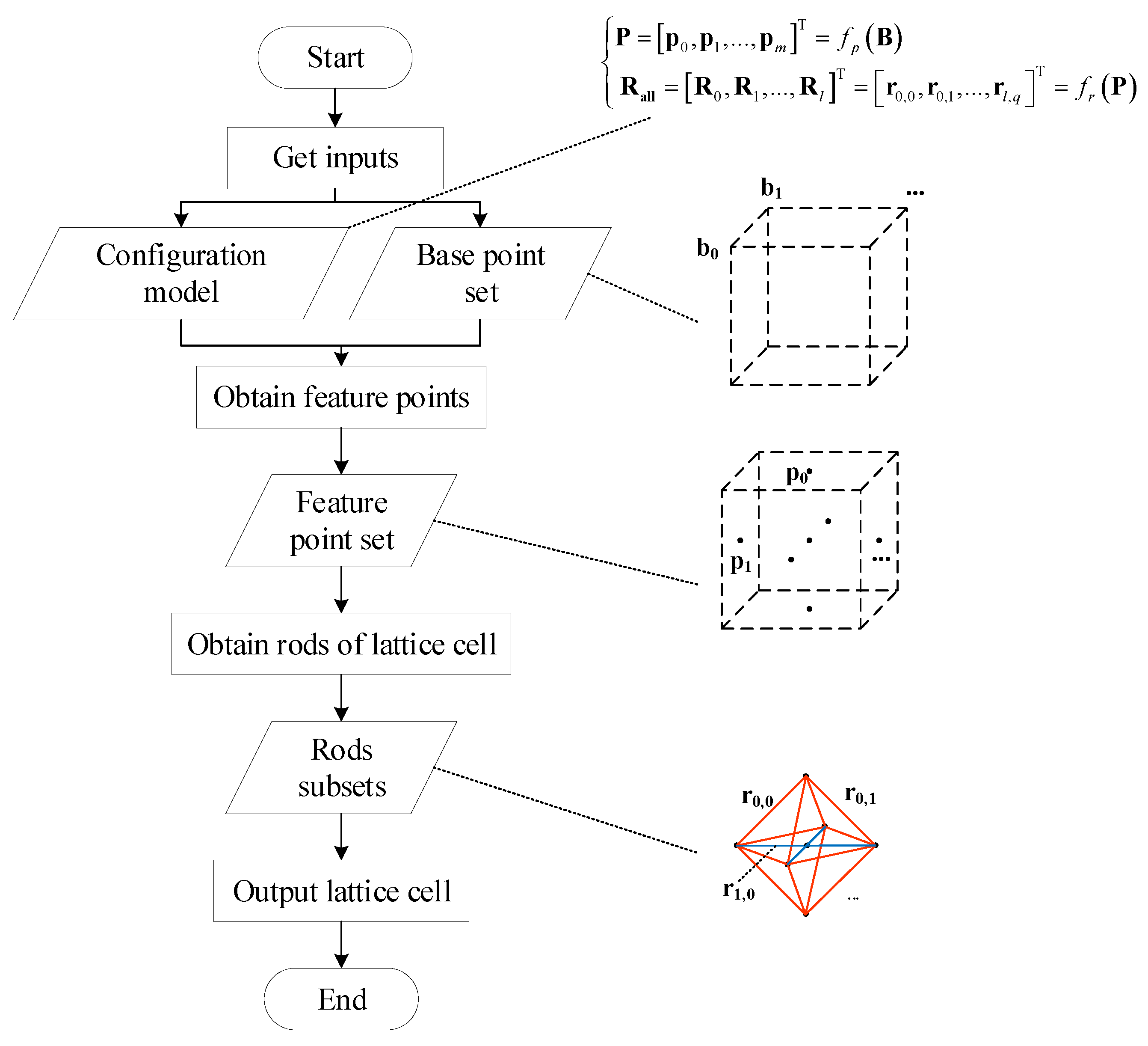
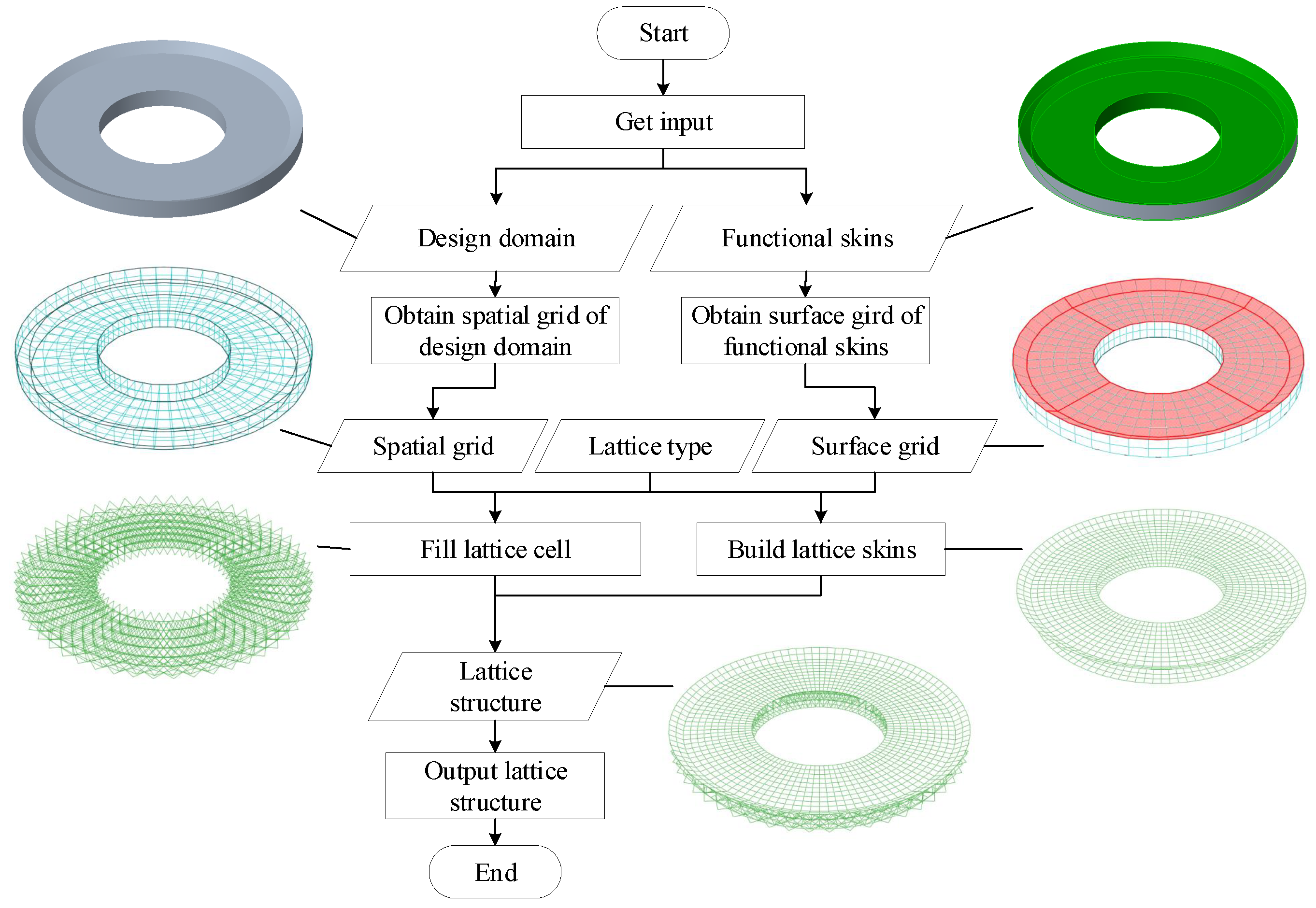
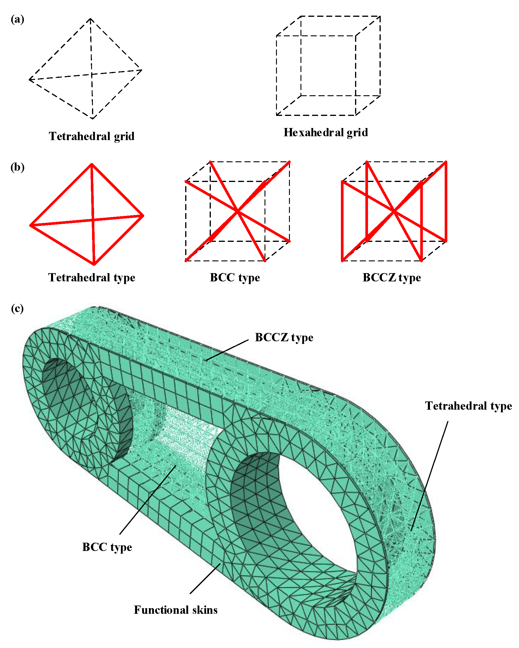
Section 3 describes the design and modeling method of lattice cell configuration and lattice structure. 
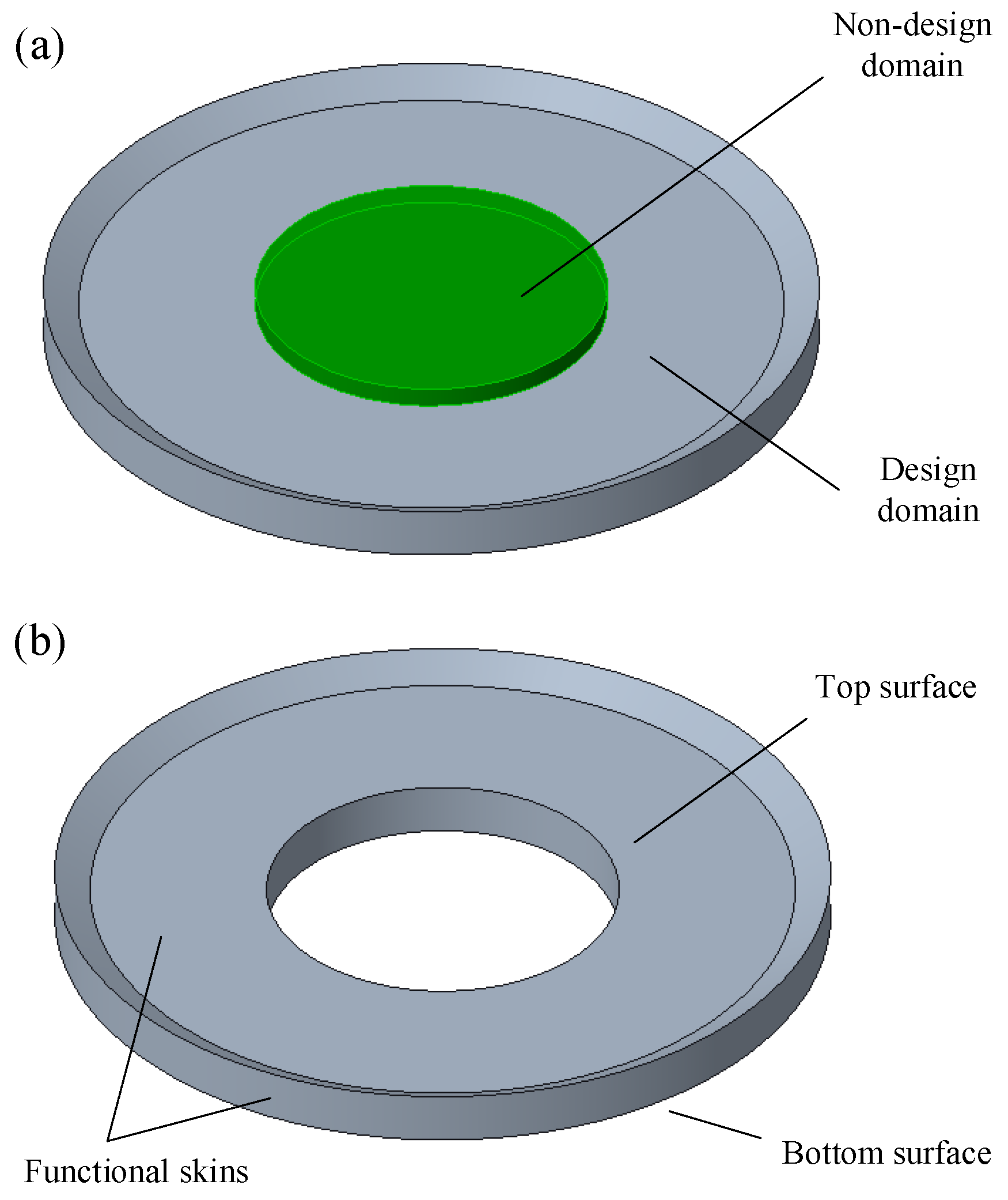
Section 4 introduces the design object and models employed in this work. Section 5 discusses the results with numerical examples to illustrate the advantages of bionic designs. Finally, the conclusions are summarized in Section 6.

2. Bamboo-Inspired Design of Lattice

2.1. Bionic Lattice Cell Configuration

Many studies have shown that bamboo has good performance in resisting axial deformation and energy absorption [35,37,38]. Therefore, in order to improve the capacity of the footpad to resist impact deformation in a certain direction while ensuring the capacity of energy absorption, bamboo is taken as a design reference. According to the vascular structure of bamboo, a lattice cell configuration with four inner reinforced rods in the Z direction, namely BCC4IZ, is proposed. Firstly, the structure of a single vascular bundle is obtained from the section of bamboo (Figure 1a). Then, the single vascular bundle and surrounding tissues are considered as a unit (Figure 1b). In the unit, the four phloem tissues of the vascular bundle structure are arranged in a diamond or rectangle shape and are connected by surrounding tissues. Inspired by this, a bionic 2D XY section, as shown in Figure 1c, is abstracted. On the other hand, the BCC cell configuration (Figure 1d) is used to simulate the tissue around the vascular bundle to disperse the load between the reinforcing structures and ensure continuity. Finally, combining the layout of the reinforced structure with the BCC configuration, the design of the BCC4IZ lattice structure, as shown in Figure 1e, is obtained, where r n is the radius of normal rods, r z is the radius of z rods, L is the length of the lattice cell on a certain edge and l is the position of z rod on that edge. For non-uniform spatial grids, the length of each edge of the lattice cell is different, but on each edge, the value of l / L is a fixed value.

2.2. The Performance of BCC4IZ

2.2.1. Effective Mechanical Properties of BCC4IZ

This paper analyzes the effective Young’s modulus of BCC4IZ when l / L = 1 / 4 and the rods in BCC4IZ have spatial symmetry. Figure 2 exhibits the stress condition of BCC4IZ under compressive load. It is assumed that rod AB and rod AC produce vertical displacement δ under the action of force F. Suppose the axial force and tangential force on the rod AB are F a 1 and F s , and the axial force on the rod AC is F a 2 . The relationship between the forces is shown in (1)
F = F a 2 + F a 1 sin φ + F s cos φ
According to the compression formula, F a 1 and F a 2 can be represented as:
F a 1 = E m π r n 2 δ sin φ a
F a 2 = E m π r z 2 δ a sin φ
According to the bending formula, F s can be represented as:
F s = 3 4 π E m r n 4 a 3 δ cos φ
where E m is the Young’s modulus of the material of the lattice structure.
Combining (1)–(4), we derive F:
F = E m π δ a r z 2 sin φ + r n 2 sin 2 φ + 3 r n 4 cos 2 φ 4 a 2
The effective compressive stress and strain in the Z direction of BCC4IZ are:
σ zz = 4 F L c 2 = 3 F 4 a 2
ε zz = δ a sin φ
Then, combining (5)–(7), we derive the effective Young’s modulus of BCC4IZ
E zz = σ zz ε zz = 3 4 E m π r z 2 a 2 + r n 2 sin 3 φ a 2 + 3 r n 4 sin φ cos 2 φ 4 a 4
Since r n is much smaller than a, therefore 3 r n 4 sin φ cos 2 φ 4 a 4 is much smaller than r z 2 a 2 and r n 2 sin 3 φ a 2 and (8) can be written as
E zz 3 E m π r z 2 + r n 2 sin 3 φ 4 a 2
This paper compared (9) with the method and tool proposed by Omairey et al. [39] under the same value, and similar results are obtained. According to the method [39] in the literature, the equivalent Poisson’s ratio of zx and zy are 0.47 ( r z = r n ).
According to the relationship in the (9), increasing r z effectively improves the E zz of BCC4IZ than increasing r n . When the mass of structure is determined, because the total length of r n is greater than that of r z , slightly reducing r n and increasing r z will significantly increase the capacity of lattice cells to resist impact deformation.

2.2.2. Energy Absorption and Deformation of BCC4IZ

In order to analyze the energy absorption and deformation of BCC4IZ lattice cells in the cushioning process, we established the lattice cell structure specimen and analysis model, as shown in Figure 3.
The initial speed is 1 m/s and the load is 1 t, 0.8 t and 0.6 t, respectively. Explicit dynamic analysis was carried out in ABAQUS software. The time histories of the kinetic energy of specimen E k , s are shown in Figure 4. The values of initial kinetic energy E in , s and obtained end kinetic energy E end , s are shown in Table 1. The results demonstrate that BCC4IZ can effectively absorb the impact energy under three loads.
At the end of the impact process, the deformation of a unit cell under three loads are shown in Figure 5. With the increase of the load, the deformation of the unit cell also increases, but the deformation trend is nearly identical. The main deformation of the rods is bending, which occurs not only in the vertical plane but also in the horizontal plane, as shown in Figure 6.

2.2.3. Manufacturing Feasibility of BCC4IZ

The specimen of BCC4IZ was manufactured by the SLM method of additive manufacturing, as displayed in Figure 7. The material of the specimen is AlSi 1 0 Mg , which is one of the most common metal additive manufacturing materials. There are 15 lattice cells in the specimen and the parameters of BCC4IZ are as follows: r z = r n = 1 mm , L = 10 mm, and l / L = 1 / 3 . BCC4IZ is self-supporting, and there is no internal support inside the specimen. The manufacturing quality of the specimen is excellent and correctly reflects the design characteristics of BCC4IZ, which proves that the novel lattice configuration can be manufactured.

2.3. Bionic Design for Layout of Lattice

For the layout of vascular bundles in bamboo shown in Figure 8a, it can be observed that the vascular bundle structure is staggered in the radial direction of the bamboo. Thus, the bionic layout for the lattice cell, as shown in Figure 8b, can be obtained. The shaded and white grids can adopt different lattice configurations, respectively, thus forming different lattice structures.

3. Lattice Design and Modeling Methods

3.1. Lattice Cell Configuration Design Method

In order to realize the parametric design of various lattice cells, a lattice cell configuration design method based on a spatial base point is proposed. This method mainly contains two inputs, configuration model C M , and spatial base point set B = b 0 , b 1 , , b n T . Each b i is a base point, it contains information such as the location of the base point in the space and the topological relationship between the base point and other structures. B can represent the envelope of each lattice cell structure and the lattice cells are connected by envelopes. The C M is a model to express the relationship between the base point set and lattice cell structure. It contains the type, direction, and constraints of a lattice cell, and is shown as
P = p 0 , p 1 , , p m T = f p B R all = R 0 , R 1 , , R l T = r 0 , 0 , r 0 , 1 , , r l , q T = f r P
where P is the feature point set of the lattice cell, each p i is a feature point, which can be obtained by one or more base points, R all is the rod set of lattice cell, R j is a rod subset, and r j , k is a rod. Each rod connects two feature points, and rods between different subsets have different structural characteristics, such as radius, section shape, etc.
In this method, different cell configurations can be designed by establishing different C M . Meanwhile, it is necessary to ensure that the lattice cell configuration meets the following rules:
(1) The geometry of lattice cells is composed of rods. This method is suitable for truss-like lattice structures. The geometric features in lattice cells can be simplified to a rod structure rather than a surface or solid structure; (2) Lattice cells can form periodic continuous structures in at least one direction; (3) The lattice structure formed by lattice cells shall not have discontinuous parts.
According to the above two inputs, the lattice cell structure can be defined. The process of this method is demonstrated in Figure 9.

3.2. Lattice Structure Design and Modeling Method

In order to design a lattice structure with the lattice cells designed by the method in Section 3.1, a design and modeling method of lattice structure based on variable spatial grid is proposed in this section. The main idea of this method is to divide the design domain into approximately uniform and periodic spatial grids and to fill lattice cells within each spatial grid. The process of the proposed method is shown in Figure 10.
The inputs of this method are the spatial design domain and functional surfaces of the design structure. The spatial design domain is the area where the lattice structure is designed and filled. The functional surfaces are the design area of the lattice structure skins. Then, the design domain and functional surface are divided into spatial grids and surface grids by the algorithm. For each surface grid, we build a skinned model that matches the lattice cell type. According to the selected lattice cell configuration and through the design method demonstrated in Section 3.1, we deleted each individual lattice cell filled into this spatial grid, thereby forming a continuous lattice structure composed of multiple lattice cells in the design domain. Finally, we combined the lattice cells with the skin to obtain a complete lattice structure.
For spatial grids, the type of each grid is independent while ensuring that the grid is continuous and effectively fills the design domain. Furthermore, a variety of designs can be formed by filling various lattice cell configurations in different positions. Based on the method in Section 3.1, different grids (Figure 11a) can be used to design a variety of commonly used lattice cells. For example, a hexahedral grid can be designed as BCC or BCCZ cells, as shown in Figure 11b. Based on the method in this section, various and numerous lattice cells can form a continuous lattice structure based on spatial grids, as shown in Figure 11c.

4. Bamboo Inspired Design of Landing Footpad

4.1. Design Object and Working Conditions

In this paper, the design object is a landing footpad for a lunar lander, the 3D model of the footpad is shown in Figure 12a. The center part of the footpad is attached to the landing leg and equipped with payloads such as sensors, therefore, it is not a design domain. The design domain of footpad is shown in Figure 12b, and all outer surfaces of the design domain are functional surfaces. A payload of 1 ton is attached to the top surface of the footpad. The footpad provides landing cushioning at a speed of 1 m/s in the vertical direction or 0.5 m/s in the horizontal direction. The landing ground is considered as rigid.

4.2. Designs with Different Lattice Cells

In this paper, four designs use the same spatial grid, as shown in Figure 13a. Four designs are presented for comparison, and they are named “D-BCC”, “D-BCCZ”, “D-BCC4IZ”, and “D-BIO”. Four designs are shown in Figure 13. “D-BCC”, “D-BCCZ”, and “D-BCC4IZ” filled the lattice configurations of BCC, BCCZ, and BCC4IZ in all spatial grids, respectively. “D-BIO” adopts the layout shown in Figure 8, and the BCC4IZ and BCC configurations are alternately filled in the spatial grid, as shown in Figure 14. All models are generated by the python automatic modeling script in ABAQUS software.
The parameters for the four designs are shown in Table 2. m lat is the total mass of the lattice structure excluding the skins. The mass of the structure of the above five designs is consistent. Except for D-BCC, the other three designs set the normal rod radii to 0.45 mm, and then distribute the rest of the mass to all Z rods.
The modal analysis of four designs are carried out by FEA. The results show that the fundamental frequency values of the four designs are 103–105 hz, which can avoid the damages of the footpad during launch [40].

5. Results and Discussion

In this paper, ABAQUS software is used for FEA modeling and analysis. The material parameters used in the model are shown in Table 3.
Rods in four designs are discretized into 3–6 elements according to the size of lattice, so as to ensure that the element size between the different models are approximately the same as L / 4 . The total time and interval of the analysis are set to 0.05 s and 0.001 s, respectively. The calculation time for each simulation is about 2 h.

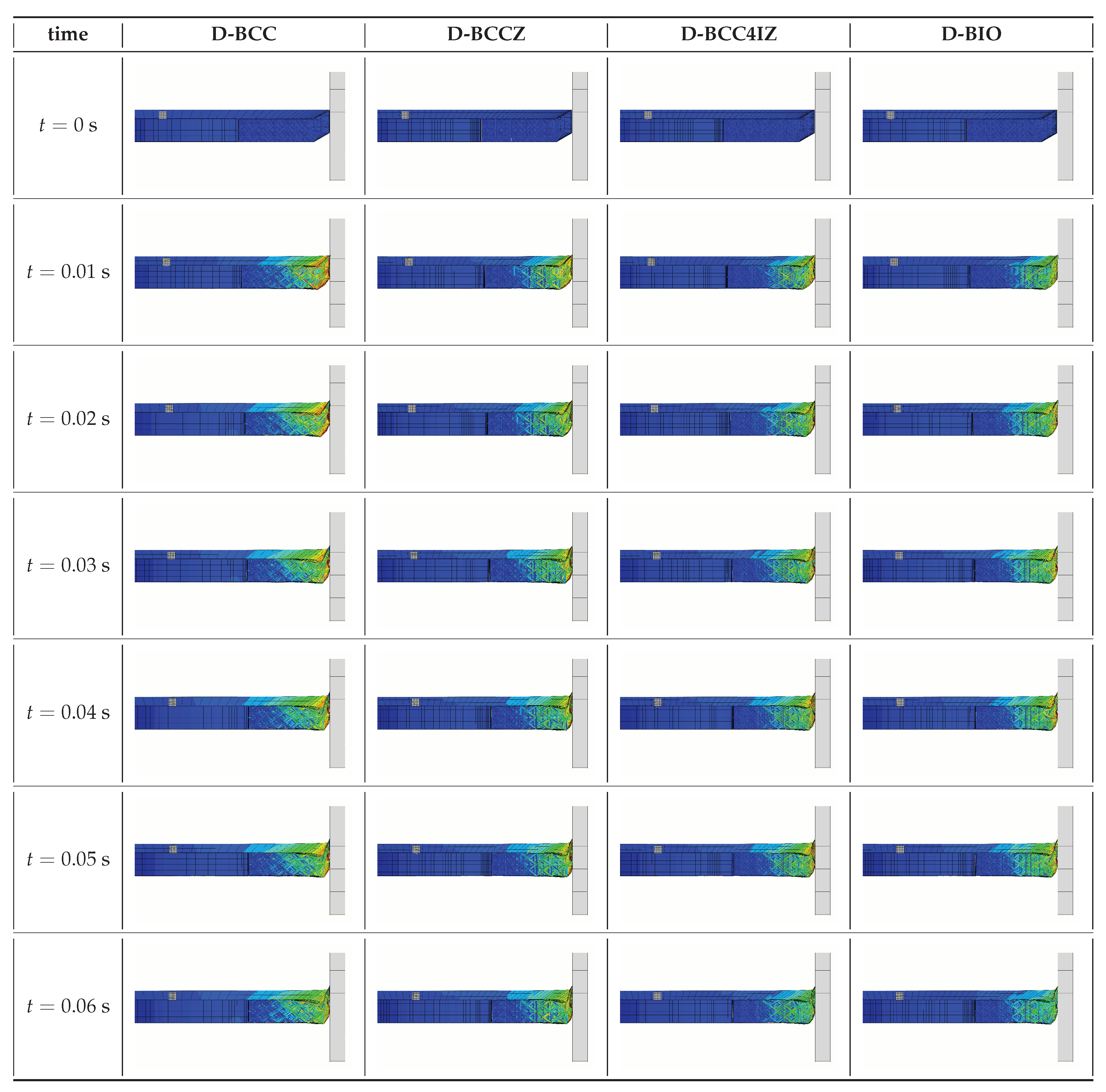
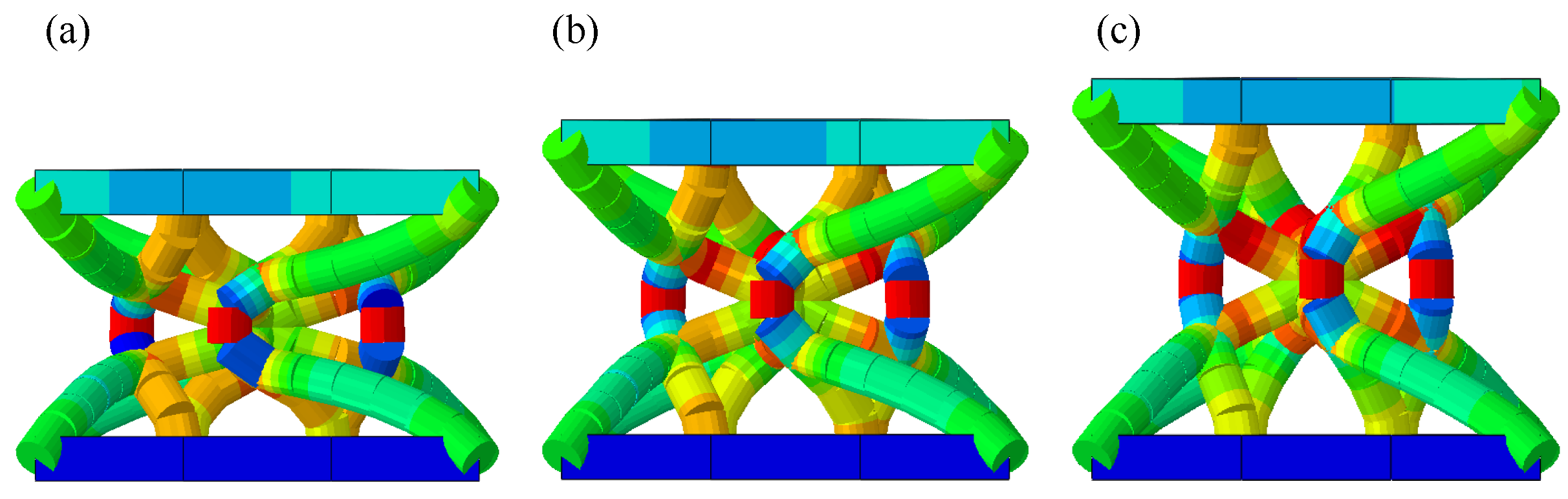
5.1. Condition 1: Vertical Cushioning

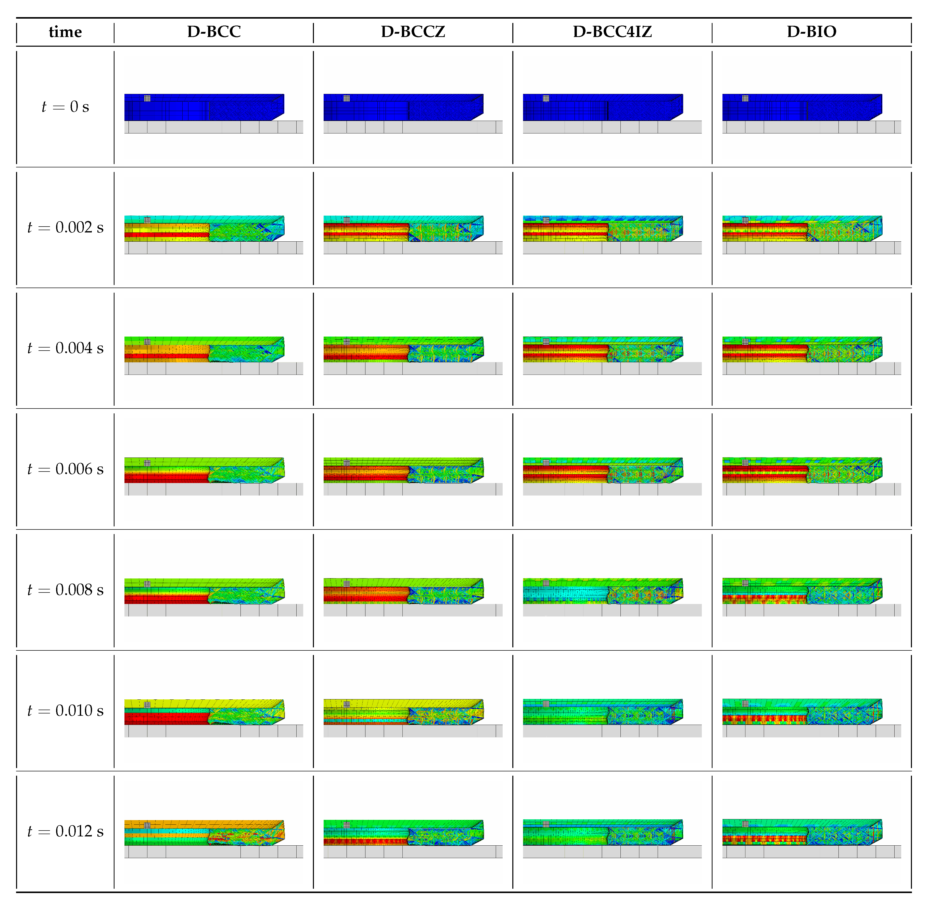
The landing cushioning process of the four designs are shown in Figure 15.
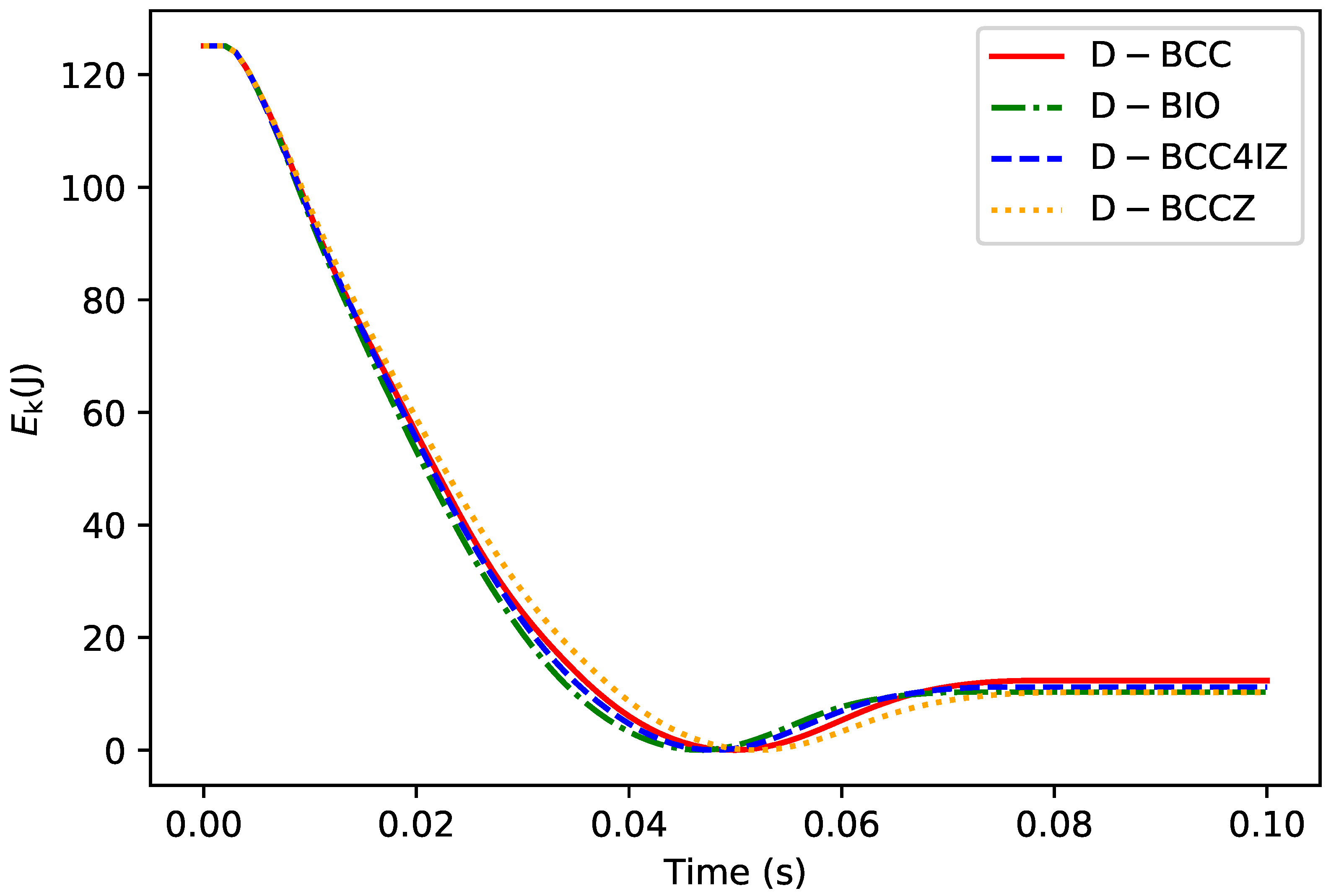
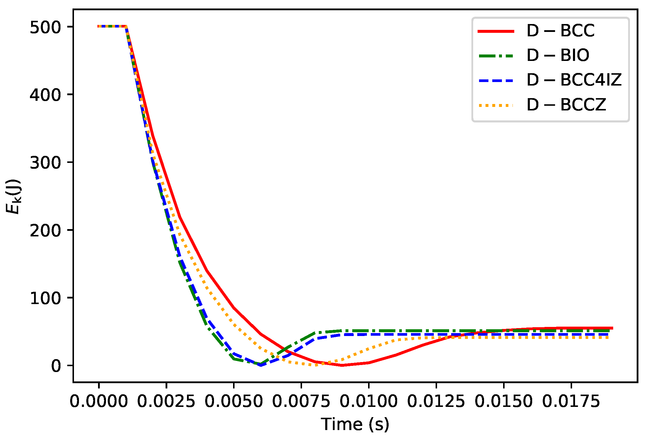
The results show that in the vertical landing condition, the cushioning process of different designs is generally similar and lasted about 0.01 s. After 0.012 s, each design begins to move vertically upwards. Meanwhile, the structure rebounded and the deformation decreased. In this paper, the kinetic energy changes before and after cushioning are concerned to evaluate the energy absorption performance of the different designs. The kinetic energy E k curves of the four designs are shown in Figure 16.
As listed in Table 4, the initial kinetic energy of the four designs are the same due to the fact that all the designs have the same total mass and the same initial velocity. The final D-BCC kinetic energy is slightly higher than other designs, and the final kinetic energy of the other designs are similar.
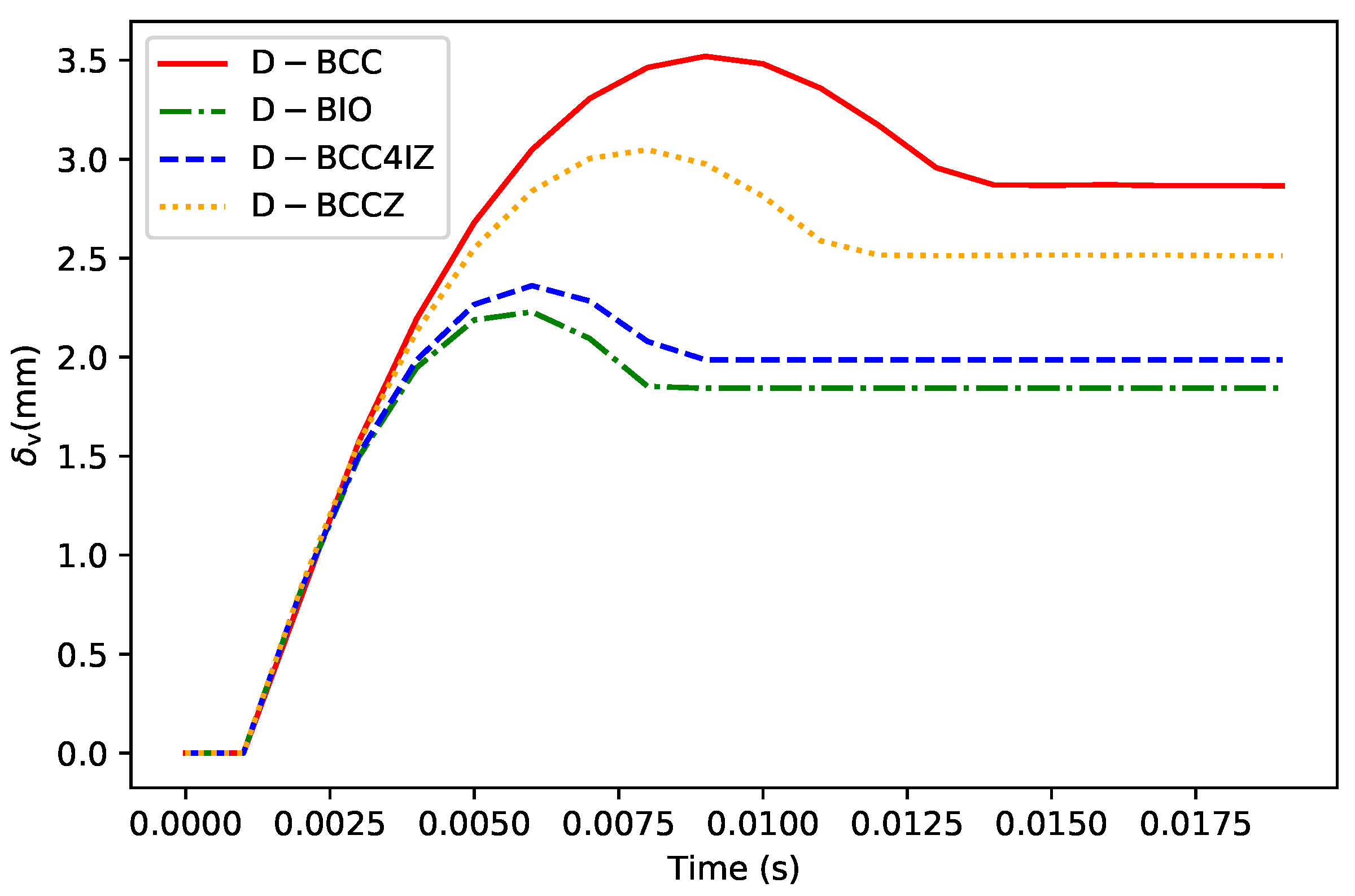
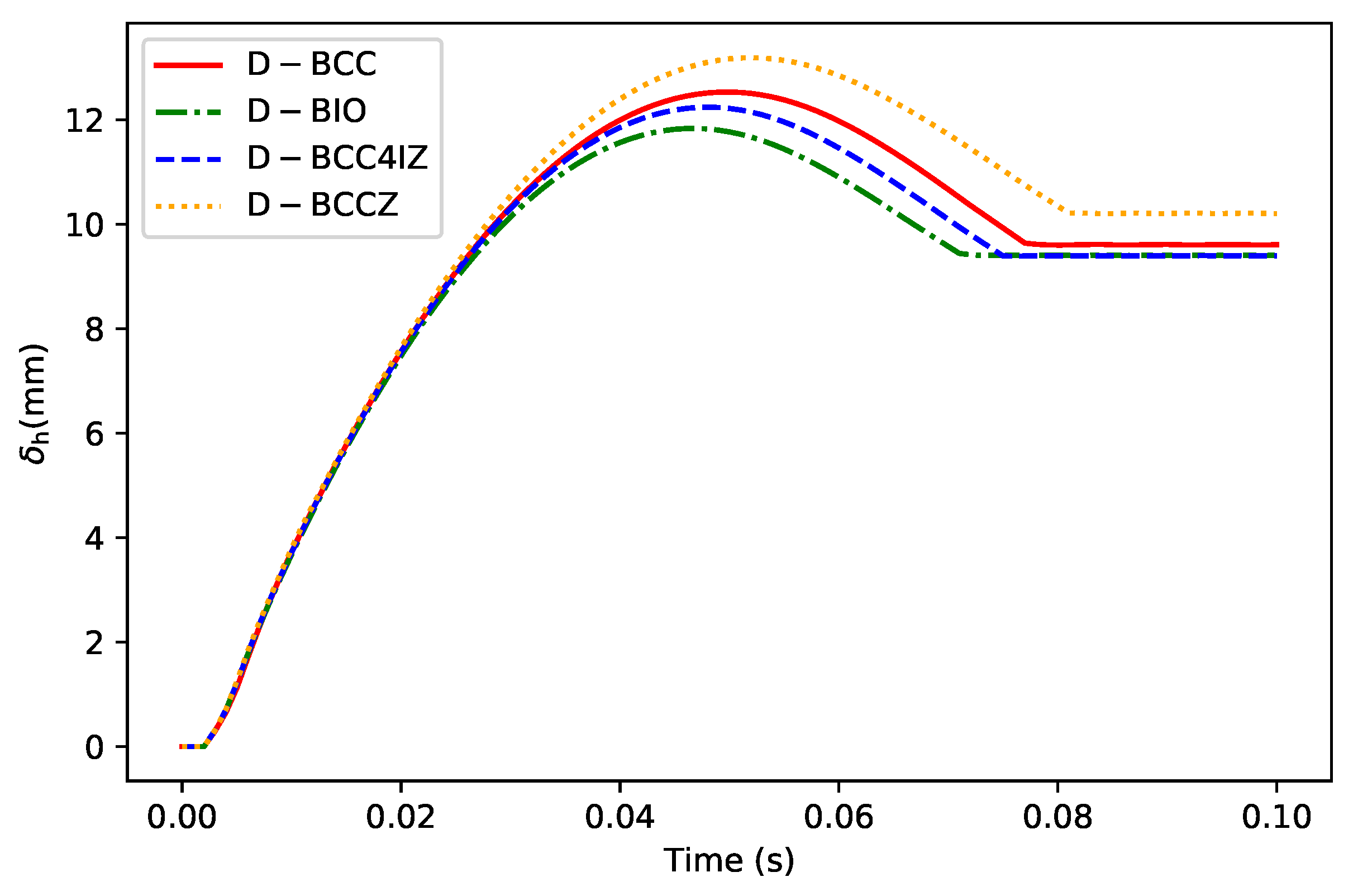
On the other hand, we further consider the deformation of the footpad during the cushioning process. The changing distance between the two points at top and bottom surfaces of the structure is used to measure the deformation in the vertical direction as δ v . The time histories of δ v for the four designs are shown in Figure 17 and the maximum and end values of them are listed in Table 5.
According to the results, the bionic design of D-BCC4IZ and D-BIO has better capacity against impact deformation than D-BCC and D-BCCZ. In terms of the value of δ v , max , D-BCC4IZ is 32.9 % and 22.5 % lower than D-BCC and D-BCCZ, respectively; meanwhile, those of D-BIO are 36.7 % and 26.8 % lower than D-BCC and D-BCCZ, respectively. According to the parameters, the values of total mass for Z rods in D-BCCZ, D-BCC4IZ, and D-BIO are the same; however, D-BIO adopts a different layout of lattice, so that the mass is distributed more reasonably.

5.2. Condition 2: Horizontal Cushioning

The landing cushioning process of the four designs is shown in Figure 18.
The kinetic energy E k of the four designs is shown in Figure 19 and Table 6.
Similar to Section 4.1, the changing distance between the two points of the structure to measure the deformation in the horizontal direction as δ h and the time histories of δ h for the four designs are shown as Figure 20 and the maximum and end values of them are listed in Table 7.
The four designs show no significant difference in energy absorption. However, unlike that in Section 4.1, the deformation of D-BCCZ in the horizontal direction exceeds that of D-BCC. This is because the Z rods of D-BCCZ cannot increase the rigidity of the structure in the horizontal direction, but instead separate the mass of the normal rods. On the other hand, although not as obvious in the vertical direction, the capacity of resisting impact deformation of D-BCC4IZ and D-BIO in the horizontal direction is also better than that of D-BCC and D-BCCZ.

6. Conclusions

To improve the cushioning performance of the landing footpad, this study proposes a bionic design method of the non-uniform lattice structure. Firstly, based on the vascular of bamboo structure, a lattice cell configuration BCC4IZ and a bionic layout are proposed. In order to establish the model of lattice structure using the above design, this paper proposes a lattice cell configuration design and modeling method. Then, four footpad designs with different lattice configurations and layouts are presented and analyzed under vertical and horizontal cushioning conditions. Finally, the results of E k and δ are compared to evaluate the performance of the different designs. The conclusions are summarized as follows.
(1) The design and modeling methods proposed in this paper successfully parameterized the configuration and layout of the bionic design. Both bionic configuration and layout are also correctly applied to the design of the footpad, which proves the effectiveness of the design and modeling methods;
(2) For vertical cushioning, the numerical values of E k and δ v indicate that the BCC4IZ cell is similar to BCC and BCCZ in terms of energy absorption while it is superior to them in terms of the vertical capacity of resisting impact deformation. During the cushioning process, δ v , max of D-BCC4IZ decreased by 32.9 % and 22.5 % compared with that of D-BCC and D-BCCZ, respectively. It shows that the BCC4IZ cell configuration can effectively improve the impact deformation resistance of the structure in the vertical direction;
(3) For horizontal cushioning, there is no significant difference in the energy absorption performance of the D-BCC, D-BCCZ, and D-BCC4IZ. However, compared with D-BCC, D-BCCZ has a higher δ h in the horizontal direction. This is because the presence of the Z rods in D-BCCZ divides part of the mass from normal rods under the constraint of the given total mass, resulting in the reduction of the horizontal capacity of resisting impact deformation. However, the D-BCC4IZ cell configuration with Z rods has the same overall mass as D-BCCZ, but its δ h is lower than D-BCC and D-BCCZ. The reason for the above results is that most of the Z rods in BCCZ do not participate in the horizontal impact process, but the Z rods and normal rods in BCC4IZ form a stable shape and cut the normal rods into smaller ones, which indirectly reduces the δ h in the horizontal direction. The results of the two cases show that the cell configuration of BCC4IZ outperforms BCC and BCCZ in the overall impact deformation resistance;
(4) Furthermore, this paper obtained the fourth design D-BIO of the footpad by combining BCC4IZ and bamboo-inspired alternative layout. Due to the reduced number of BCC4IZ in D-BIO, the overall length of the z rods decreased, but the mass is distributed more equitably. Compared with that of D-BCC, D-BCCZ, and D-BCC4IZ, the maximum deformation of D-BIO in the vertical direction is reduced by 36.7 % , 26.8 % , and 5.6 % , respectively. Horizontally, the D-BIO also slightly outperforms the D-BCC4IZ. It further proves the validity of the design method combining bionic design and lattice structure.

Author Contributions

Conceptualization, H.D. and J.Z.; methodology, H.D.; software, H.D.; validation, H.D., J.Z. and C.W.; formal analysis, H.D.; investigation, H.D. and J.Z.; resources, C.W.; data curation, H.D.; writing—original draft preparation, H.D.; writing—review and editing, H.D. and J.Z.; visualization, H.D.; supervision, C.W.; project administration, C.W.; funding acquisition, C.W. All authors have read and agreed to the published version of the manuscript.

Funding

This research was supported by the National Natural Science Foundation of China (Grant No51635002).

Institutional Review Board Statement

Not applicable.

Informed Consent Statement

Not applicable.

Data Availability Statement

Not applicable.

Conflicts of Interest

The authors declare no conflict of interest.

References

  1. Ashby, M.; Cebon, D. Materials Selection in Mechanical Design. J. Phys. IV Fr. 1993, 3, C7-1–C7-9. [Google Scholar] [CrossRef] [Green Version]
  2. Mines, R.A.; McKown, S.; Tsopanos, S.; Shen, E.; Cantwell, W.J.; Brooks, W.; Sutcliffe, C. Local Effects during Indentation of Fully Supported Sandwich Panels with Micro Lattice Cores. Appl. Mech. Mater. 2008, 13–14, 85–90. [Google Scholar] [CrossRef] [Green Version]
  3. Marco, M.; Belda, R.; Miguélez, M.H.; Giner, E. Numerical Analysis of Mechanical Behaviour of Lattice and Porous Structures. Compos. Struct. 2021, 261, 113292. [Google Scholar] [CrossRef]
  4. Feng, L.J.; Xiong, J.; Yang, L.H.; Yu, G.C.; Yang, W.; Wu, L.Z. Shear and Bending Performance of New Type Enhanced Lattice Truss Structures. Int. J. Mech. Sci. 2017, 134, 589–598. [Google Scholar] [CrossRef]
  5. Liu, Y.; Dong, Z.; Ge, J.; Lin, X.; Liang, J. Stiffness Design of a Multilayer Arbitrary BCC Lattice Structure with Face Sheets. Compos. Struct. 2019, 230, 111485. [Google Scholar] [CrossRef]
  6. Lei, H.; Li, C.; Meng, J.; Zhou, H.; Liu, Y.; Zhang, X.; Wang, P.; Fang, D. Evaluation of Compressive Properties of SLM-fabricated Multi-Layer Lattice Structures by Experimental Test and μ-CT-based Finite Element Analysis. Mater. Des. 2019, 169, 107685. [Google Scholar] [CrossRef]
  7. Peng, C.; Tran, P.; Nguyen-Xuan, H.; Ferreira, A. Mechanical Performance and Fatigue Life Prediction of Lattice Structures: Parametric Computational Approach. Compos. Struct. 2020, 235, 111821. [Google Scholar] [CrossRef]
  8. Deshpande, V.S.; Fleck, N.A.; Ashby, M.F. Effective Properties of the Octet-Truss Lattice Material. J. Mech. Phys. Solids 2001, 49, 1747–1769. [Google Scholar] [CrossRef] [Green Version]
  9. Korshunova, N.; Alaimo, G.; Hosseini, S.; Carraturo, M.; Reali, A.; Niiranen, J.; Auricchio, F.; Rank, E.; Kollmannsberger, S. Image-Based Numerical Characterization and Experimental Validation of Tensile Behavior of Octet-Truss Lattice Structures. Addit. Manuf. 2021, 41, 101949. [Google Scholar] [CrossRef]
  10. Li, J.; Chen, D.; Zhang, Y.; Yao, Y.; Mo, Z.; Wang, L.; Fan, Y. Diagonal-Symmetrical and Midline-symmetrical Unit Cells with Same Porosity for Bone Implant: Mechanical Properties Evaluation. J. Bionic Eng. 2019, 16, 468–479. [Google Scholar] [CrossRef]
  11. Ozdemir, Z.; Tyas, A.; Goodall, R.; Askes, H. Energy Absorption in Lattice Structures in Dynamics: Nonlinear FE Simulations. Int. J. Impact Eng. 2017, 102, 1–15. [Google Scholar] [CrossRef]
  12. Ozdemir, Z.; Hernandez-Nava, E.; Tyas, A.; Warren, J.A.; Fay, S.D.; Goodall, R.; Todd, I.; Askes, H. Energy Absorption in Lattice Structures in Dynamics: Experiments. Int. J. Impact Eng. 2016, 89, 49–61. [Google Scholar] [CrossRef] [Green Version]
  13. Niknam, H.; Akbarzadeh, A. Graded Lattice Structures: Simultaneous Enhancement in Stiffness and Energy Absorption. Mater. Des. 2020, 196, 109129. [Google Scholar] [CrossRef]
  14. Liu, Y.; Zhang, J.; Tan, Q.; Yin, Y.; Li, M.; Zhang, M.X. Mechanical Performance of Simple Cubic Architected Titanium Alloys Fabricated via Selective Laser Melting. Opt. Laser Technol. 2021, 134, 106649. [Google Scholar] [CrossRef]
  15. Walker, E.L.; Jin, Y.; Reyes, D.; Neogi, A. Sub-Wavelength Lateral Detection of Tissue-Approximating Masses Using an Ultrasonic Metamaterial Lens. Nat. Commun. 2020, 11, 5967. [Google Scholar] [CrossRef] [PubMed]
  16. Zubov, Y.; Djafari-Rouhani, B.; Jin, Y.; Sofield, M.; Walker, E.; Neogi, A.; Krokhin, A. Long-Range Nonspreading Propagation of Sound Beam through Periodic Layered Structure. Commun. Phys. 2020, 3, 155. [Google Scholar] [CrossRef]
  17. Lee, Y.H.; Lee, B.K.; Jeon, I.; Kang, K.J. Wire-Woven Bulk Kagome Truss Cores. Acta Mater. 2007, 55, 6084–6094. [Google Scholar] [CrossRef]
  18. Brunet, T.; Merlin, A.; Mascaro, B.; Zimny, K.; Leng, J.; Poncelet, O.; Aristégui, C.; Mondain-Monval, O. Soft 3D Acoustic Metamaterial with Negative Index. Nat. Mater. 2015, 14, 384–388. [Google Scholar] [CrossRef]
  19. Hyun, S.; Karlsson, A.; Torquato, S.; Evans, A. Simulated Properties of Kagomé and Tetragonal Truss Core Panels. Int. J. Solids Struct. 2003, 40, 6989–6998. [Google Scholar] [CrossRef] [Green Version]
  20. Ushijima, K.; Cantwell, W.; Mines, R.; Tsopanos, S.; Smith, M. An Investigation into the Compressive Properties of Stainless Steel Micro-Lattice Structures. J. Sandw. Struct. Mater. 2011, 13, 303–329. [Google Scholar] [CrossRef]
  21. Smith, M.; Guan, Z.; Cantwell, W. Finite Element Modelling of the Compressive Response of Lattice Structures Manufactured Using the Selective Laser Melting Technique. Int. J. Mech. Sci. 2013, 67, 28–41. [Google Scholar] [CrossRef]
  22. Pham, M.S.; Liu, C.; Todd, I.; Lertthanasarn, J. Damage-Tolerant Architected Materials Inspired by Crystal Microstructure. Nature 2019, 565, 305–311. [Google Scholar] [CrossRef] [PubMed]
  23. Bian, Y.; Yang, F.; Li, P.; Wang, P.; Li, W.; Fan, H. Energy Absorption Properties of Macro Triclinic Lattice Structures with Twin Boundaries Inspired by Microstructure of Feldspar Twinning Crystals. Compos. Struct. 2021, 271, 114103. [Google Scholar] [CrossRef]
  24. Bian, Y.; Li, P.; Yang, F.; Wang, P.; Li, W.; Fan, H. Deformation Mode and Energy Absorption of Polycrystal-Inspired Square-Cell Lattice Structures. Appl. Math. Mech. 2020, 41, 1561–1582. [Google Scholar] [CrossRef]
  25. Li, W.; Fan, H.; Bian, Y.; Yang, F. Plastic Deformation and Energy Absorption of Polycrystalline-like Lattice Structures. Mater. Des. 2021, 198, 109321. [Google Scholar] [CrossRef]
  26. Yang, C.; Li, Q. Advanced Lattice Material with High Energy Absorption Based on Topology Optimisation. Mech. Mater. 2020, 148, 103536. [Google Scholar] [CrossRef]
  27. Fernandes, M.C.; Aizenberg, J.; Weaver, J.C.; Bertoldi, K. Mechanically Robust Lattices Inspired by Deep-Sea Glass Sponges. Nat. Mater. 2021, 20, 237–241. [Google Scholar] [CrossRef]
  28. Sharma, D.; Hiremath, S.S. Bio-Inspired Repeatable Lattice Structures for Energy Absorption: Experimental and Finite Element Study. Compos. Struct. 2022, 283, 115102. [Google Scholar] [CrossRef]
  29. Li, J.; Xu, H.; Yu, Y.; Chen, H.; Yi, W.; Wang, H. Intelligent Analysis Technology of Bamboo Structure. Part I: The Variability of Vascular Bundles and Fiber Sheath Area. Ind. Crop. Prod. 2021, 174, 114163. [Google Scholar] [CrossRef]
  30. Xu, H.; Li, J.; Ma, X.; Yi, W.; Wang, H. Intelligent Analysis Technology of Bamboo Structure. Part II: The Variability of Radial Distribution of Fiber Volume Fraction. Ind. Crop. Prod. 2021, 174, 114164. [Google Scholar] [CrossRef]
  31. Zhang, Q.; Mao, J.; Li, C.; Han, H.; Lin, J.; Wang, F.; Wang, L. Bamboo-Inspired Lightweight Tape Suture with Hollow and Porous Structure for Tendon Repair. Mater. Des. 2020, 193, 108843. [Google Scholar] [CrossRef]
  32. Zhao, L.; Ma, J.; Wang, T.; Xing, D. Lightweight Design of Mechanical Structures Based on Structural Bionic Methodology. J. Bionic Eng. 2010, 7, S224–S231. [Google Scholar] [CrossRef]
  33. Ray, A.K.; Mondal, S.; Das, S.K.; Ramachandrarao, P. Bamboo—A Functionally Graded Composite-Correlation between Microstructure and Mechanical Strength. J. Mater. Sci. 2005, 40, 5249–5253. [Google Scholar] [CrossRef]
  34. Sato, M.; Inoue, A.; Shima, H. Bamboo-Inspired Optimal Design for Functionally Graded Hollow Cylinders. PLoS ONE 2017, 12, e0175029. [Google Scholar] [CrossRef]
  35. Fu, J.; Liu, Q.; Liufu, K.; Deng, Y.; Fang, J.; Li, Q. Design of Bionic-Bamboo Thin-Walled Structures for Energy Absorption. Thin-Walled Struct. 2019, 135, 400–413. [Google Scholar] [CrossRef]
  36. Xu, T.; Liu, N.; Yu, Z.; Xu, T.; Zou, M. Crashworthiness Design for Bionic Bumper Structures Inspired by Cattail and Bamboo. Appl. Bionics Biomech. 2017, 2017, 5894938. [Google Scholar] [CrossRef]
  37. Chen, B.; Zou, M.; Liu, G.; Song, J.; Wang, H. Experimental Study on Energy Absorption of Bionic Tubes Inspired by Bamboo Structures under Axial Crushing. Int. J. Impact Eng. 2018, 115, 48–57. [Google Scholar] [CrossRef]
  38. Xing, D.; Chen, W.; Ma, J.; Zhao, L. Structural Bionic Design for Thin-Walled Cylindrical Shell against Buckling under Axial Compression. Proc. Inst. Mech. Eng. Part C J. Mech. Eng. Sci. 2011, 225, 2619–2627. [Google Scholar] [CrossRef]
  39. Omairey, S.L.; Dunning, P.D.; Sriramula, S. Development of an ABAQUS Plugin Tool for Periodic RVE Homogenisation. Eng. Comput. 2019, 35, 567–577. [Google Scholar] [CrossRef] [Green Version]
  40. Chen, L. Spacecraft Structures and Mechanisms; Science and Technology of China Press: Hefei, China, 2005. (In Chinese) [Google Scholar]
Figure 1. The bamboo-inspired design of lattice cell configuration as BCC4IZ (a) Bamboo section (photo is taken by the first author) (b) Vascular bundle of bamboo (c) Bionic 2D Section (d) BCC lattice (e), and BCC4IZ lattice.
Aerospace 09 00220 g001
Figure 2. Stress condition of BCC4IZ under compressive load.
Aerospace 09 00220 g002
Figure 3. Impact analysis of BCC4IZ. (a) BCC4IZ specimen; (b) Analysis model.
Aerospace 09 00220 g003
Figure 4. Kinetic energy of the specimen with different loads.
Aerospace 09 00220 g004
Figure 5. The deformation of a unit cell with different loads. (a) 1 t; (b) 0.8 t; (c) 0.6 t.
Aerospace 09 00220 g005
Figure 6. The deformation of a unit cell in the horizontal plane.
Aerospace 09 00220 g006
Figure 7. The specimen manufactured by SLM. (a) CAD model of the specimen; (b) the BCC4IZ specimen.
Aerospace 09 00220 g007
Figure 8. The bamboo-inspired design of lattice cell layout: (a) layout of vascular bundle (the photo is taken by the first author); (b) bionic layout for lattice cells.
Aerospace 09 00220 g008
Figure 9. The process of the lattice cell structure design method.
Aerospace 09 00220 g009
Figure 10. The process of lattice cell structure design and modeling method.
Aerospace 09 00220 g010
Figure 11. Combinations of various spatial grids and lattice cells. (a) Spatial grids; (b) Lattice cells; (c) Lattice structure.
Aerospace 09 00220 g011
Figure 12. The 3D model of the footpad. (a) Footpad; (b) lattice structure design domain.
Aerospace 09 00220 g012
Figure 13. Spatial grids and lattice structure of the four designs. (a) Spatial grids; (b) D-BCC; (c) D-BCCZ; (d) D-BCC4IZ; (e) D-BIO.
Aerospace 09 00220 g013
Figure 14. Alternative layout of the lattice cell structure of D-BIO.
Aerospace 09 00220 g014
Figure 15. Landing cushioning process magnitude displacement results of the four designs under vertical cushioning condition.
Aerospace 09 00220 g015
Figure 16. Comparison of E k .
Aerospace 09 00220 g016
Figure 17. Comparison of δ v .
Aerospace 09 00220 g017
Figure 18. Landing cushioning process magnitude displacement results of the four designs under a horizontal cushioning condition.
Aerospace 09 00220 g018
Figure 19. Comparison of E k .
Aerospace 09 00220 g019
Figure 20. Comparison of δ h .
Aerospace 09 00220 g020
Table 1. The kinetic energy value of the specimen.
Load1 t0.8 t0.6 t
E in , s / J 50.0 40.0 30.0
E end , s / J 1.036 0.952 0.887
Δ E k , s / E in , s 97.9 % 97.6 % 97.0 %
Table 2. The parameters of four designs.
DesignD-BCCD-BCCZD-BCC4IZD-BIO
r n / mm 0.5 0.45 0.45 0.45
r z / mm - 0.6974 0.3183 0.4502
m lat / kg 0.170
Table 3. The parameters of the material.
ParametersValue
Density/ ( kg / m 3 ) 2680
Young’s modulus/ MPa 61,000
Poisson’s ratio0.3
Yield strength/ MPa 210
Tensile strength/ MPa 354
Maximum strain0.1
Table 4. The E k value of four designs.
DesignD-BCCD-BCCZD-BCC4IZD-BIO
E k , 0 / J 500.50
E k , end / J 55.01 41.20 45.74 51.28
Δ E k / J 445.04 458.85 454.31 448.77
Δ E k / E k , 0 88.92 % 91.68 % 90.77 % 89.66 %
Table 5. The δ v value of four designs.
D-BCCD-BCCZD-BCC4IZD-BIO
δ v , max / mm 3.520 3.048 2.361 2.228
δ v , end / mm 2.864 2.514 1.986 1.843
Table 6. The E k value of the four designs.
DesignD-BCCD-BCCZD-BCC4IZD-BIO
E k , 0 / J 125.13
E k , end / J 12.35 10.26 11.21 10.32
Δ E k / J 112.78 114.87 113.92 114.81
Table 7. The δ h value of four designs.
DesignD-BCCD-BCCZD-BCC4IZD-BIO
δ h , max / mm 12.53 13.19 12.24 11.83
δ h , end / mm 9.61 10.20 9.40 9.40
Publisher’s Note: MDPI stays neutral with regard to jurisdictional claims in published maps and institutional affiliations.

