5.1. Assumptions
Basically, two key assumptions are needed to find a solution to the CDA problem (3). As will be demonstrated by the Fast Time Simulations and by the justifications reported below, they do not limit the generality of the solution that still complies with CDA key requirements too much.
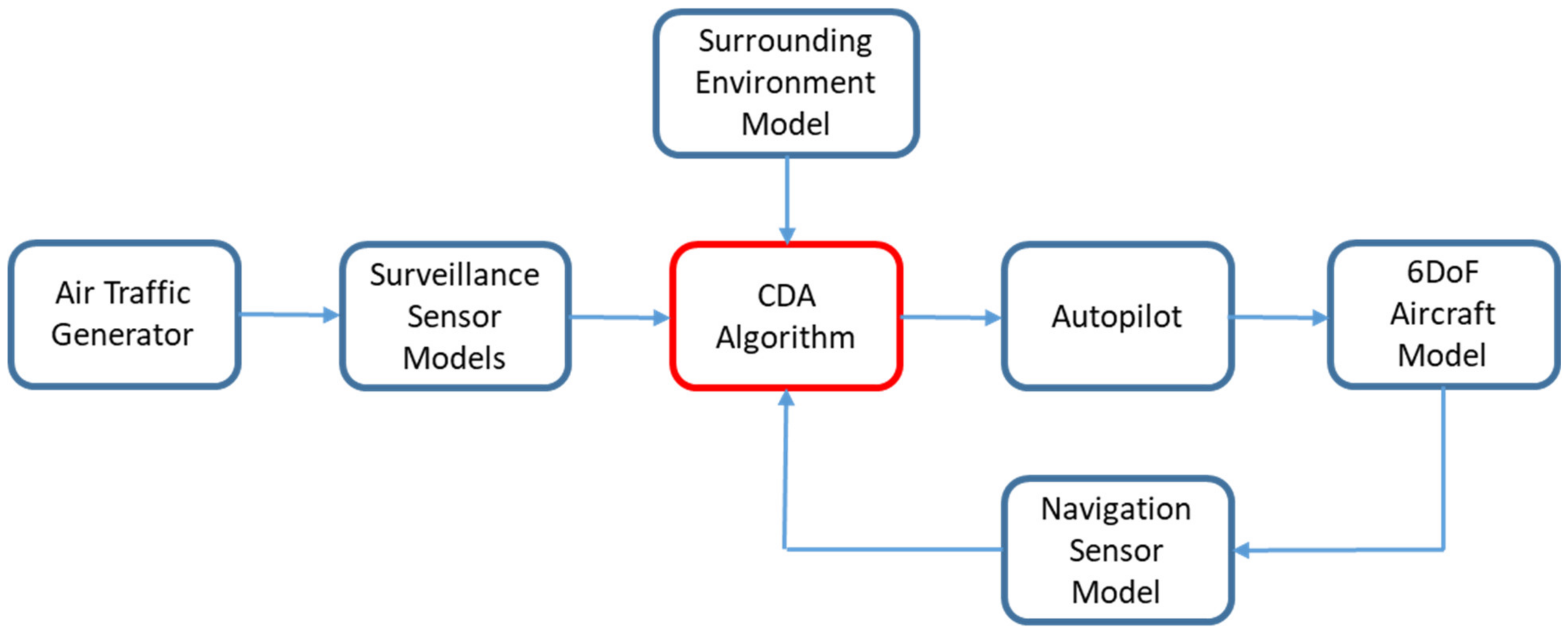
First, a simplification is introduced with reference to the non-linear dynamic constraint (3c) associated to the own aircraft. Full nonlinear 6DOF rigid-body dynamics, including limitations on real actuators, sensors and engines, should be used to produce an accurate solution that is actually reachable in the state-space trajectories of the own aircraft. However, this model is typically highly uncertain, with a very large number of parameters. Therefore, it is not suitable in a CDA implementation in a generic unmanned vehicle that could have only limited available information. Moreover, collision avoidance maneuvers are typically executed using autopilot commands, thus also the flight control system should have been included in such model.
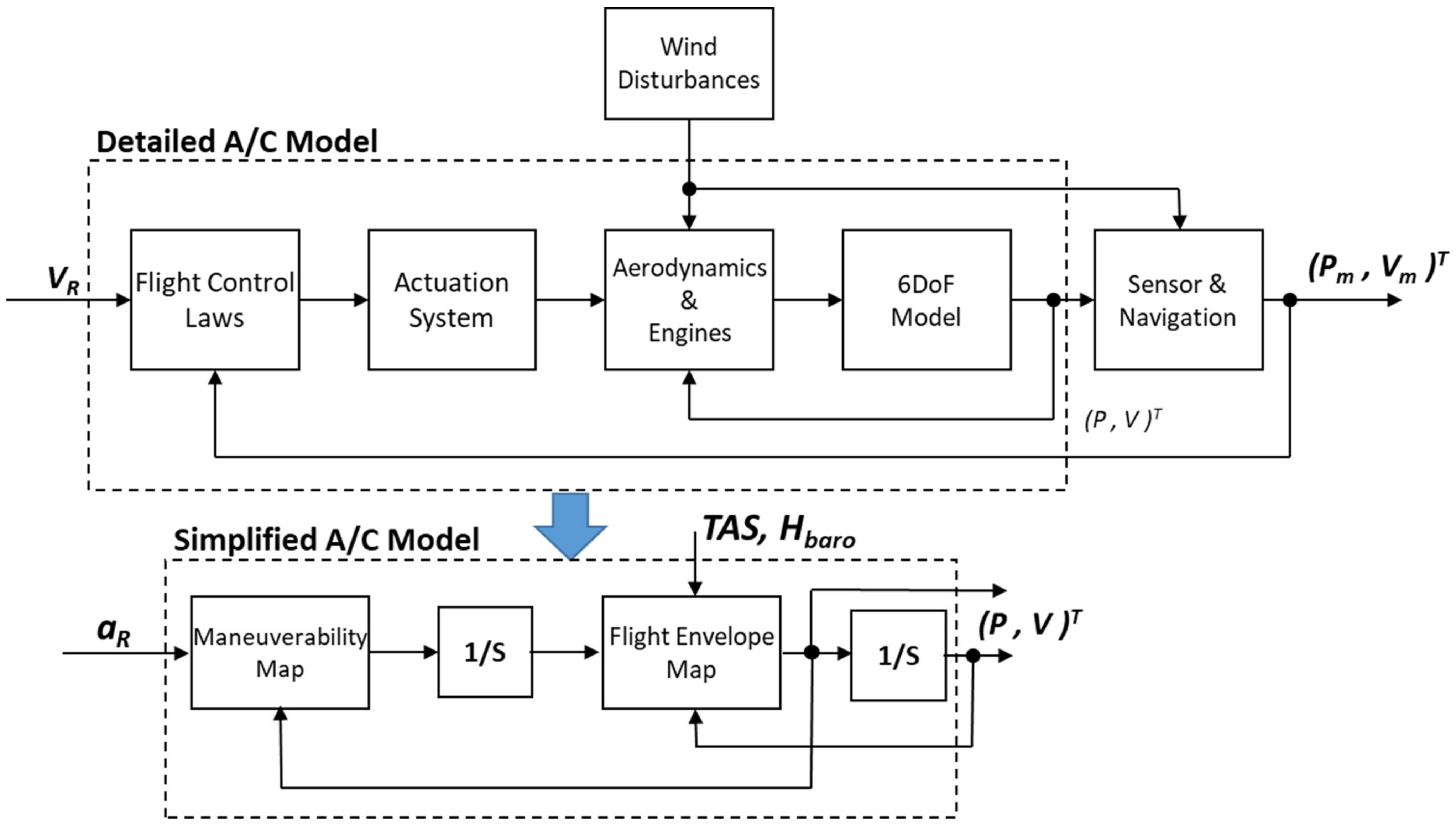
On the other hand, the CDA problem only needs good accuracy on the predicted position and velocity of the own aircraft. Therefore, considering that states related to the aircraft Center of Mass have a frequency range that is typically separated from the rigid body rotational dynamics, a 3DOF numerical model can be a very good approximation of the aircraft dynamics that fits the scope of designing a CDA algorithm. With this schematization, the aircraft limitations can be accounted for by using suitable performance and flight envelope static maps as follows (see also
Figure 4):
where linear accelerations are given by the maneuverability map
fMan that depend on some commanded accelerations
aR and current aircraft velocity. The flight envelope limitations are given by another map
fEnv that limits the velocity states based on the current positions and inertial velocities (mainly altitude and speed). In a first attempt, these maps can be implemented with maximum and minimum accelerations and velocities of the aircraft on each axis or, in a more accurate modelling, as a function of barometric altitude and airspeed measurements (or other parameters where relevant), so including the limitations on aerodynamic and thrust forces. However, it will be pointed out that they refer to the closed loop performance and flight envelope of the aircraft. The above maps can be also changed to degrade aircraft performances to accommodate some non-critical failures (e.g., reduced actuation speed, engine failure in a dual engine aircraft, etc.).
The second key assumption is related to the avoidance maneuver command profiles. In this paper, it is considered that the aircraft can perform single axis maneuvers (either right/left turn or climb/descend) and that any of these maneuvers is performed at its maximum acceleration (given by the maneuverability map) applied instantaneously to the related axis until a desired velocity change is obtained (limited by the flight envelope map) and then removed instantaneously again. After this change, the velocity vector is kept constant until the Look-Ahead Time T. When performing such maneuvers, the 3D wind field estimated by the on-board navigation system and the True Air Speed are considered constant, so that the initial and final inertial speeds can be different. Constant wind is assumed because of the relatively short timeframe of CDA, so that time and space variation of the wind could be considered negligible. Finally, in order to approximately account for the vehicle dynamics reaching the maximum horizontal and vertical accelerations, the maneuver is started with a (constant) time latency referred to as ‘On Set Time’.
With these command profiles, the avoidance maneuver is defined using a single parameter for each of the axes (i.e., the final velocity).
While the above command sets might seem very limiting for the scope of a CDA, it should be noted that they are easily acceptable and executable by a remote pilot. These aspects are of paramount importance when remotely piloting a vehicle, because a pilot is always the final party responsible for the aircraft. Maximum accelerations are used because the collision avoidance maneuver is normally a last resort command that, therefore, needs the fastest response by the aircraft. Airspeed changes are not considered because the resolution maneuver could be not ‘visible’ by the intruder pilot.
Finally, it shall be noted that, not considering airspeed changes, single axis maneuvers do not limit the range of possible maneuvers as much because the algorithm can command another maneuver on a different axis soon after the first one has been completed or while it is being executed.
5.2. Trajectory Prediction of Air Traffic and Own Aircraft
Based on problem formulation (3), a key function of the CDA algorithm is the prediction of both ownship and air traffic. The information related to air traffic concerns the position and velocity of the aircraft (intruders) that are in some proximity to the own unmanned vehicle and are provided by the so-called traffic surveillance sensors. Two types of such sensors are available [
9] and will be considered in this paper:
Cooperative Sensors, which require some equipment to be on board the intruder to send radio messages allowing determination of its position and velocity. The most common sensors of this type are the Active Traffic sensors or Interrogators, which need a transponder mode A/C or S on the intruder able to answer to a radio interrogation with a given message enclosing some data (e.g., Aircraft Identifier and Altitude). Further examples are the ADS-B-IN sensors, which receive radio messages from intruders equipped with a Transponders Mode S-ES (Extended Squitter) that regularly transmits intruders’ data without any need to be interrogated. These sensors typically have a very long range of detection (from 20 NM up to 50 NM), no field-of-view limitations and very good accuracy, except for the Interrogators that normally have a very low bearing accuracy.
Non-Cooperative Sensors, that do not need the intruder to be equipped with any device and, therefore, can potentially detect any flying object depending on sensor’s capabilities. An example of such sensors are Radars that send radio-frequency pulses and gather position and velocity measurements from the reflected signals (active sensors), and Video Cameras (passive sensors) that produce the images of the surroundings to determine the presence and the trajectory of intruders. These sensors typically have very short ranges of detection (from 2 NM of cameras up to about 7 NM for air-to-air-radars), a limited field of view (most of the time [−110…110] deg in azimuth and [−15…15] deg in elevation) and good accuracy of range (for radars) and azimuth/elevation (for cameras).
In this paper, it is considered that a suite of both Cooperative and Non-Cooperative sensors is available. The measurements are fused and processed so as to provide a consolidated estimate of position, inertial velocity and related accuracy of the surrounding air traffic. Where needed, this consolidated intruder state is estimated considering a constant wind field, as provided by the on-board navigation system. Even if the algorithms used to process the raw measurements coming from the available traffic, surveillance sensors are not within the scope of this paper; it is worth noting that data fusion of sensors’ measurements is needed because each sensor has its own advantages and weaknesses over the other, as above summarized. With the above assumptions on surveillance sensors and related processing algorithms, this paper considers that intruders of any type can be detected even if at different ranges and with different accuracies.
With a consolidated set of tracks available (i.e., intruders’ position and inertial velocity) with related accuracies, the first step of a CDA algorithm is to predict their trajectories over the time horizon [tk, tk + T]. As has been declared, one of the most adopted techniques is to consider the projection of the position using the current intruder’s velocity vector (straight trajectory prediction). In this paper we consider a more general trajectory prediction technique that is also able to give an estimate of the prediction accuracy.
Each intruder is modelled as a hybrid dynamic model, with continuous and discrete states, as follows:
where the continuous states
are the predicted position, velocity and accelerations of the
i-th intruder,
σi is the prediction error,
mik is the discrete state representing the flight mode of the intruder (straight and level, right turn, etc.) and
Si is information related to the type of the CDA algorithm installed on board the intruder (e.g., TCAS-II) that can come from the processing of traffic surveillance sensors. The maps
and
are pre-fixed and depend on the current flight mode. The function
is a finite Markov chain that can be static (if the intruder is assumed to not change its flight mode) or time-variable in the case some information on the intruder’s flight plan being available from the surveillance sensors.
The parameters related to the above intruder’s trajectory prediction model are estimated using the past and current available traffic measurements from traffic surveillance sensors. To this end, this paper adopts the method based on Residual-Mean Interacting Multiple Model, described in detail in [
16,
17]. These methods provide a sub-optimal identification of the current flight mode and of the key parameters for predicting intruders’ trajectory and the associated accuracy:
where
Uk and
are the current intruder measurements and their accuracy. In this way it is possible to consider intruders’ maneuvers (where possible, given the current sensed accuracy), variable sensor measurement errors and reliability of the trajectory prediction.
Concerning the prediction of the own aircraft inertial trajectory, the measurement and related accuracy estimation can come from both the on-board navigation system and from the Flight Management System (FMS). In case the unmanned aircraft is manually piloted, the trajectory can be predicted using the same procedure adopted for the intruders. However, in this paper a straight trajectory is considered in this paper because it is more understandable by the remote pilot. On the other hand, when an automatic flight is being performed, the parameters for predicting the future ownship trajectory and related errors can be directly derived from the FMS.
Finally, note that using the above method is not essential for the proposed CDA algorithm. Other different methods can be used to obtain trajectory and error predictions. Obviously, the final results could vary depending on the accuracy of the chosen method.
5.3. Risk Assessment of the Flight Scenario and Its Evolution
The core of the proposed CDA algorithm is the method used for evaluating whether the air traffic and/or the surrounding environment can be a threat to the safety of flight in the chosen future time horizon or Look-Ahead Time (LAT) T. Moreover, it is also necessary to quantitatively estimate the level of collision risk associated to the possible evolutions of the current scenario. In this way, suitable (and autonomous) decisions could be taken, sufficiently in advance, whether or not issuing a collision alarm and, in that case, performing an automatic escape maneuver.
To this end, the proposed CDA algorithm not only evaluates potential collisions given the current air traffic and ownship trajectory predictions, but also tries to understand what happens in case of maneuvers, so to obtain indications regarding all possible evolutions of the current scenario. Indeed, as will be clearer in the following sections, the proposed quantification of risk level, used for taking decisions, is defined by the remaining possibilities of performing some escape maneuvers in the future rather than just evaluating a predicted conflict with one or more intruders, such as any current CDA method. This is the key for solving the CDA problem with an arbitrary number of intruders and path constraints, because the above defined risk level is only dependent upon ownship possibilities to safely continue the flight and not specifically influenced by any of these hazards.
To understand how this risk level can be computed, let us first reconsider the constraints (3a) and (3b) of the CDA problem and, specifically, the evaluation of the conflict probability related to the intruders (3a). Similar considerations can be performed for the path constraints (3b).
First, it can be easily verified that, when the predicted horizontal and vertical distances between ownship and intruder show very low accuracy, the probability of a collision over the time horizon
T can be very low (and below the threshold
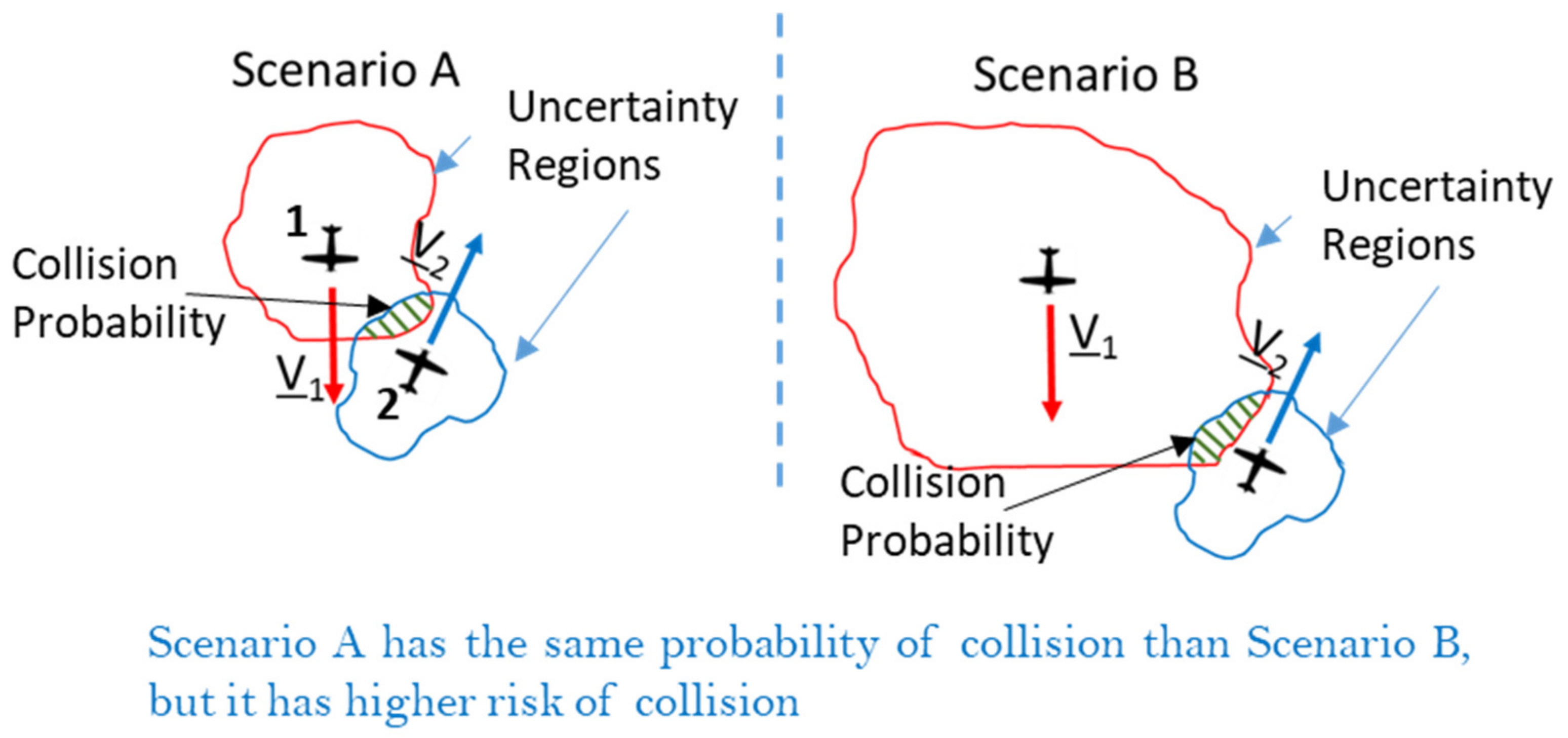
ε) even if a specific intruder can be a potential collision threat. This situation is depicted in the
Figure 5 where two intruders with different trajectory prediction accuracy have the same probability of collision if strictly computed using (3a).
In other terms, simply using the probability of collision would require that the threshold be variable with the accuracy of prediction (which is also variable along the predicted trajectories). To avoid this, the concept of
Relative Probability (
RPr) of collision as an index of the conflict threat level is introduced. The
RPr is defined as the ratio between the maximum probability of collision with the current encounter geometry and the maximum probability that would be obtained in a perfect collision situation (i.e., when the distance to the Closest Point of Approach is predicted to be 0). In mathematical terms, given the following function of collision probability as a variable of time that shall be evaluated over the time horizon
T:
where
dHA and
hA are, respectively, the average values of distance and relative altitude between the generic intruder and the ownship and
σ their accuracy; the related maximum probability of collision over the time horizon
T can be written as:
where
is the moment in time at which the collision probability has its maximum value. Then, using Equations (7) and (8), the
RPr index for a given intruder encounter is defined as:
Considering the above definition, it can be easily verified that Scenario A of
Figure 5 has a higher
RPr than that of Scenario B, according to the evidence that the former poses a higher risk of collision between the two aircraft. Moreover, it can also be intuitively noted that the
RPr is less sensitive to possible variations of the accuracy on distance and relative altitude, because this quantity is present in both the numerator and denominator of definition (9).
Anyway, RPr is still an index related to a single encounter or potential conflict with a surrounding fixed obstacle, while the proposed CDA algorithm needs to quantify the risk level associated to any possible hazard, also evaluating possible maneuvers.
To this aim, let us first note that the
RPr index can only assume values in the compact set [0…1]. A small maneuver of either the ownship or the intruder is likely to produce only small variation in this value, so we can consider the
RPr a continuous function of the ownship maneuvers. We recall here that, following the assumption of
Section 5.1, the possible maneuvers that the ownship can perform are characterized by a single value (track angle or vertical velocity for the horizontal and vertical axes, respectively). Therefore, for each intruder or fixed obstacle, the
RPr function can be evaluated on a suitable grid of ownship commands for each type of CA maneuver. The number of points on the grid is a tuning parameter and shall be determined based on the variability of the probability and on the resolution that is requested for the final velocity value. Verification of the
RPr continuity with respect to ownship maneuvers shall be verified a posteriori with numerical simulations in different encounter scenarios, as well as by performing grid spacing tuning.
Now, let us evaluate, at a given time
tk and for each intruder and path constraint
ν in 1…
N + M, all the maps
as a function of the own aircraft maneuvers
, where
j = 1…4 is the type of maneuver (right turn, climb, etc.) and
with
is the grid of ownship maneuvers for the
j-th maneuver type. With these maps of relative probability, it is possible to compute the following four Overall Relative Probability (
ORPr) functions:
The ORPr functions (one for each type of considered avoidance maneuver: left/right turn, climb/descend) includes almost all the information needed by the CDA algorithm for taking a decision and computing the optimal escape command, as will be described in the following sections. Actually, these functions give an estimation of the highest conflict risk level that is expected in the time horizon T in case the own aircraft either continues on the current flight path or performs a maneuver. In this sense, these functions almost completely characterize the current flight scenario and its possible evolutions, also giving detailed indications of where to go to lower the conflict risk.
The following section details the methods that can be used for estimating the relative probabilities for air traffic and the surrounding fixed obstacles, while the subsequent sections describe the computation of the optimal avoidance maneuver and the decision-making process.
Note that the above method for conflict risk level assessment does not prioritize intruders and/or fixed obstacles. All possible hazards are fairly treated, even if they are intrinsically prioritized because of the associated conflict risk level that, however, is not evidenced in the ORPr. This is in line with the philosophy of the proposed CDA algorithm, in which it is only important to understand if the own aircraft has currently, and would have future, safe maneuver margins for avoiding any conflict, no matter how many and which specific threats caused the conflict situation. On the other hand, it is possible to use the single RPr functions to identify the most hazardous threats, because they can be important to display to the remote pilot.
5.4. Estimation of the Conflict Risk Level for Each Hazard
The above method for assessing the conflict risk level associated to the current scenario and its evolution is based on the estimation of the RPr as function of the ownship maneuvers, for each intruder and obstacle from the surrounding environment. The proposed methods for such estimation are described below.
5.4.1. Air Traffic
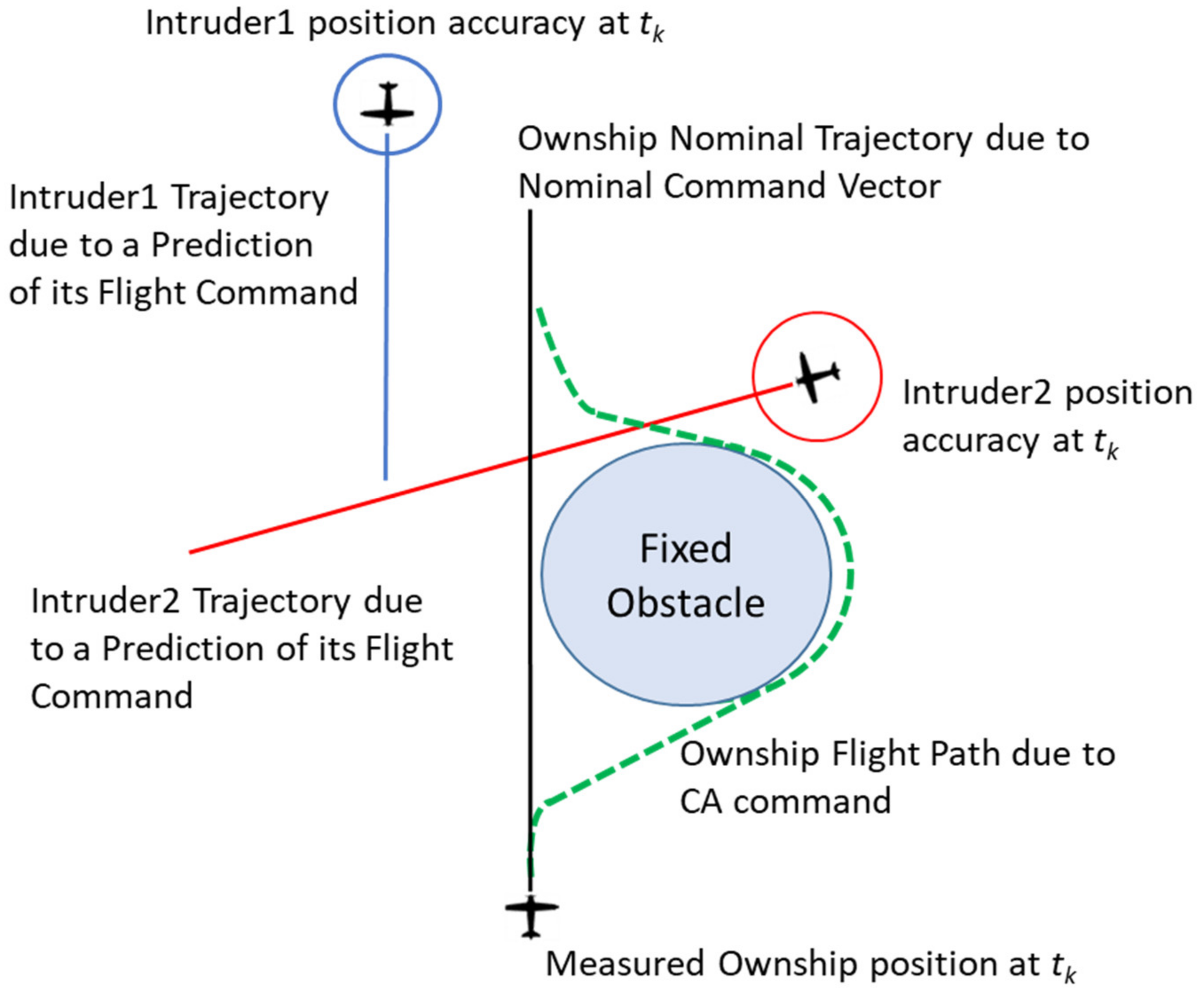
Concerning the air traffic, evaluation of the
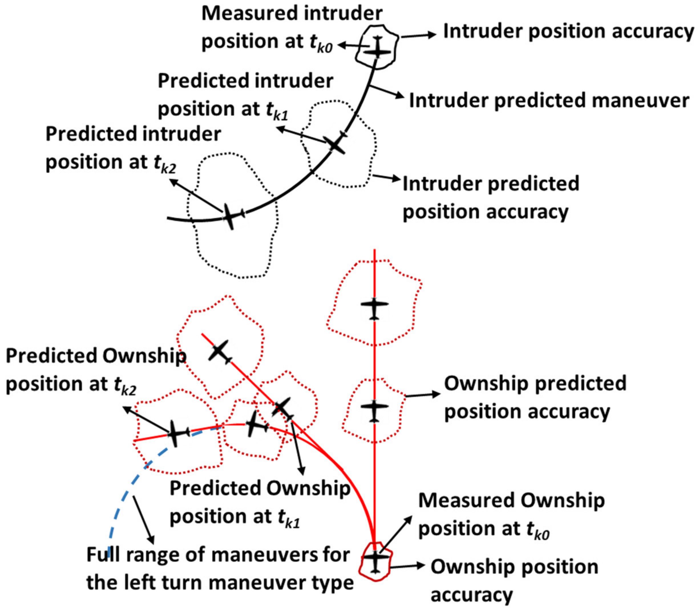
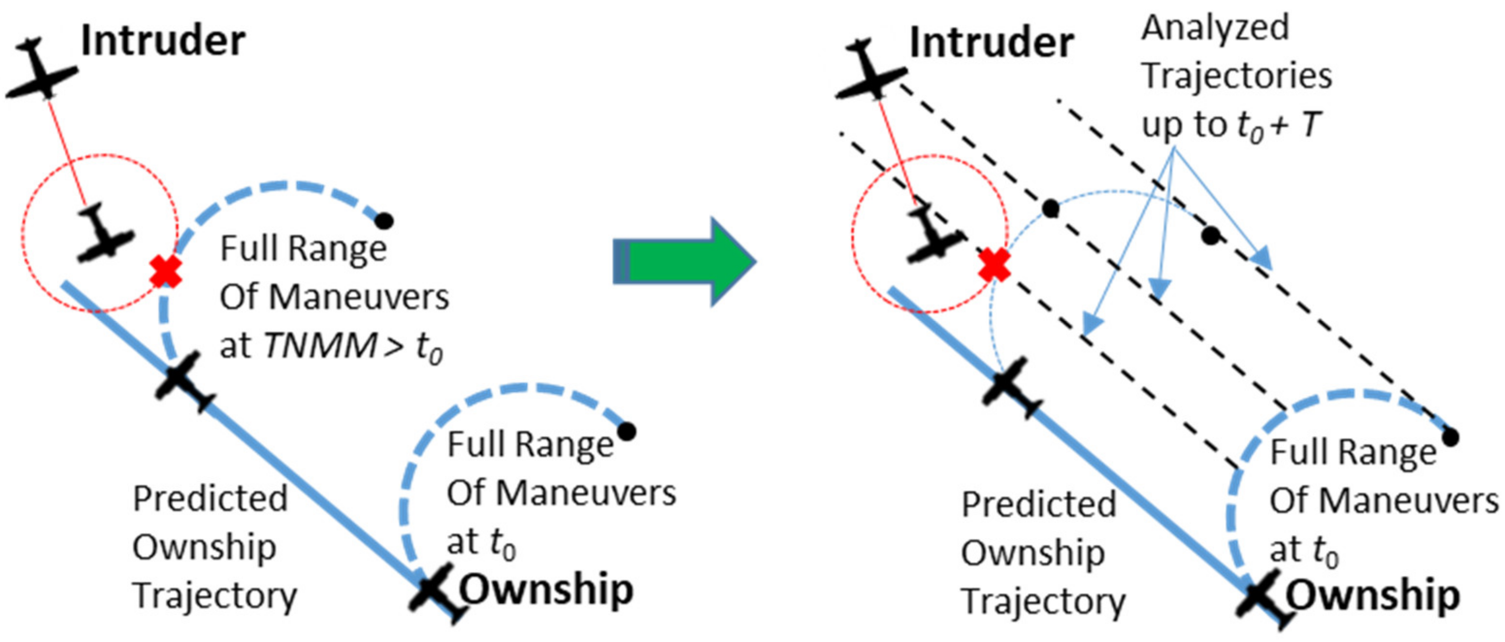
RPr functions to be used for Equation (10) is performed by first setting a given maneuver step according to the chosen fixed grid and then predicting the ownship trajectory, as depicted in the
Figure 6.
After that, using the predicted trajectories and related accuracies, Equation (7) is evaluated. To this end, several techniques can be used, such as the one proposed in [
18]. However, in this context a different method is adopted in order to reduce the computational effort at the cost of accepting some errors in estimating the relative probability.
Specifically, the
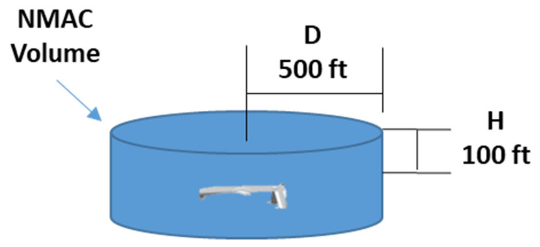
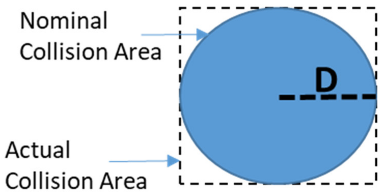
RPr is computed approximating the NMAC cylindrical volume with a right parallelogram prism (
Figure 7) and assuming that relative position coordinates between ownship and intruder
) are independent stochastic variables with time-uncorrelated Gaussian distribution.
The above assumption lets us write the probability of collision
as follows, for any
t in the look-ahead interval
T.
The probability of each Gaussian variable, namely
, of being less than the associated dimension of the NMAC volume is evaluated through an analytical approximation of the standard normal cumulative distribution function defined in [
19].
In this way, the
RPr for each intruder can be estimated as follows:
where
is the subset of intruders inside the
ν hazard set,
is the time to closest point of approach [
5] and
and
are the current relative position prediction and the current prediction error, respectively, for the
ownship maneuver evaluated at
.
The method above for computing
RPr functions is relatively simple in that it only needs the evaluation of the ownship and intruders’ trajectories prediction with related errors and
tCPA, for which several methods exist in the literature [
5,
6,
13] that can also be expressed with explicit analytical relations. On the other hand, in case cartesian relative positions cannot be used (such as in the case of relative positions in polar or cylindrical coordinates) it is possible to find a different approximation of the NMAC volume so to be again in similar conditions as requested by Equations (11) and (12). Moreover, some correlation exists between the horizontal and vertical coordinates, Equation (11) can be considered as a worst case, as this correlation is neglected in the computation.
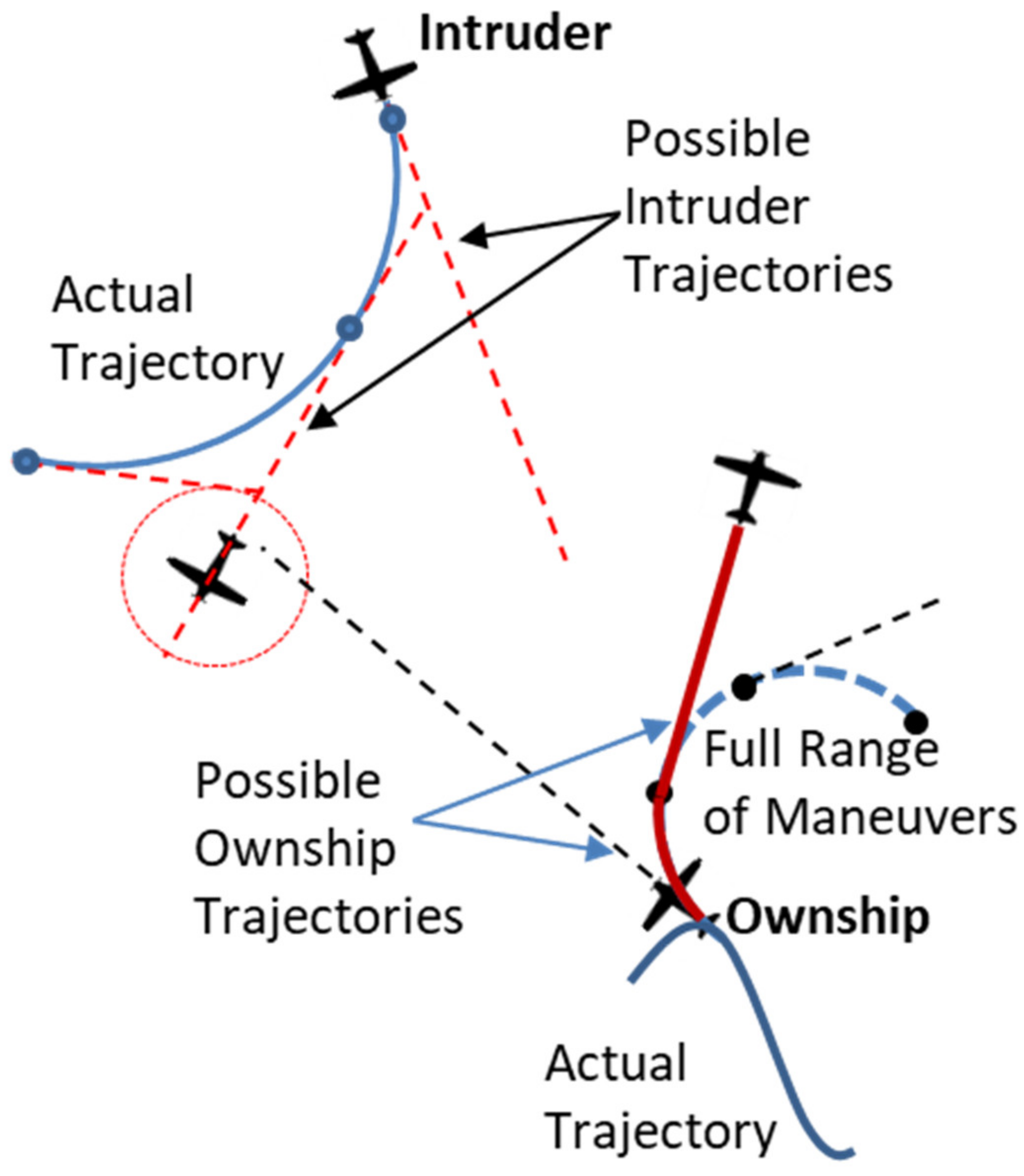
When the intruder is turning (as identified from the flight mode), the
RPr is computed by choosing the worst value between a set of trajectories that considers the intruder can stop its turn maneuver and go straight, as shown in the
Figure 8. The number of points along the intruder’s turn trajectory that are used for such assessment is an algorithm tuning parameter (the default is five points). This different way of computing
RPr for turning intruders takes into account the uncertainty in the intruder prediction trajectory.
5.4.2. Surrounding Areas and Obstacles
These hazards have very different (known) shapes from the NMAC volume, do not move (or their movements can be neglected in the timeframe of the avoidance maneuver) and typically their position is known quite accurately. Moreover, it should be pointed out that the CDA algorithm is not used for avoiding fixed obstacles, because this is a task of other on-board systems (e.g., the Terrain Avoidance and Awareness System). Therefore, a potential conflict with fixed obstacles only would not start any avoidance maneuver, unless air traffic is also involved. In this case, the air traffic avoidance maneuver accounts for these path constraints. Finally, the computation considering generic path constraints usually requires high computational effort, so it should be as simple as possible.
These differences with air traffic lead to the conclusion that the above method is not fully suitable for RPr computation in this case. Nevertheless, evaluation of RPr as a function of ownship maneuvers can still be performed using the same procedure above described, i.e., using a grid in the ownship possible maneuvers and computing the RPr for fixed obstacles on the resulted predicted trajectory.
Based on the above, the proposed algorithm assumes the following simple relation for surrounding areas and obstacles:
where γ is the subset of the fixed obstacles within the
ν hazard set and
is the ownship trajectory that resulted from applying a potential collision avoidance maneuver.
Equation (13) assumes that RPr can assume only two values: a maximum and a minimum probability, here valued one and zero, respectively. Adopting only two values allows computation of the RPr by evaluating geometrical intersections between boundaries of the fixed obstacles and the ownship trajectory, with an affordable computational effort. In this respect, it can be argued that this method could over-simplify the problem with a resulting low accuracy. Indeed, because the position and shape of fixed obstacles and the ownship’s trajectory are typically known with good accuracy, it can be easily verified that the collision probability with a fixed obstacle changes very rapidly from zero to one so the approximation of Equation (13) can be considered adequate for our scope. On the other hand, increasing the size of fixed obstacles with a suitable safety margin can conservatively account for the current navigation total system error of the ownship and accuracy of the position and shape of the obstacle.
Note that using one as the maximum value of the RPr implies that these hazards are always assumed as ‘hard’ path constraints, i.e., the vehicle is not allowed to enter the related forbidden areas. Anyway, in case ‘soft’ path constraints are enforced (such as bad weather areas that can be entered for some time/distance assuming a certain risk), a risk level lower than one can be specified in the Equation (13) to account for this possibility.
Finally, the parameter a ≥ 1 in Equation (13) specifies that RPr for fixed obstacles is performed over a time horizon equal to or greater than the one used for air traffic. Actually, this parameter is set to one when computing the ORPr functions used for deciding whether an avoidance maneuver is needed and is above one (and typically equal to two) when computing the optimal maneuver. This allows enough clearance from any obstacle to avoid alerts from other safety modules (such as Terrain Awareness Systems) and easing the return back to the original flight path after the conflict has been resolved.
In order to evaluate the geometrical intersections between the ownship trajectory and the obstacle, a dedicated computation procedure is implemented depending on the shape of the obstacle or area [
20]. Note that this procedure is also used to evaluate the time instant at which the intersection is detected so as to easily compute
RPr in both
T and
a·T intervals. In detail, let us denote the predicted position of the ownship vehicle in the North-East-Up (NEU) reference frame along the
i-th maneuver of the
j-th type as follows:
The following methods can be used for the types of surrounding obstacles considered in this paper.
Terrain
With reference to the terrain, Equation (15) guarantees that the trajectory altitude is always greater than the local elevation data provided by the function
H(,
).
In other terms, given the predicted trajectory of the ownship with a specific maneuver, the problem is simply to interrogate a terrain elevation database for checking that altitude of the aircraft is above the terrain elevation on the given trajectory. In this implementation, the Digital Terrain Elevation Data (DTED) Level 1 is used for modelling the terrain elevation map. Nevertheless, other terrain elevation databases can be used. Moreover, the availability of an elevation database of an urban area would also allow consideration of the presence of buildings and other similar obstacles so as to support Urban Air Mobility applications.
Cylindrical Forbidden Area
Given
xs,
ys,
rs,
hs and
Hs are the East and North positions of the center, the radius, the starting height and the ending height, respectively, of the
s-th cylindrical forbidden area, the following equation defines such constraints:
Equation (16) expresses that the ownship horizontal path does not intersect the cylindrical area, while the vehicle altitude is within the height interval of the forbidden area.
Right Prismatic Forbidden Area
Assuming that
xl,m,
yl,m are the East and North positions of the
m-th vertex and
hl,
Hl the initial and final altitudes, respectively, of the
l-th right prismatic forbidden area, the following relations define the condition for non-intersection these constraints.
where the function
mod(a,b) provides the remainder after division of
a by
b.
Equation (17) simply expresses that the ownship horizontal path does not intersect any side of the right prismatic area, while the vehicle altitude is within the height interval of the forbidden area.
Area of Operation
With reference to the area of operation (not limited in height), assuming that
xp and
yp are the East and North positions of the
p-th vertex of the area of operations, (18) expresses the non-intersecting constraints in this case.
The above methods deal only with some limited shapes. This is not limiting because more general obstacle shapes can be either obtained by merging the above ones or derived from more complex data using some dedicated software modules. For instance, bad weather areas can be included using one of the above shapes provided by dedicated software that evaluates the level of the hazard of the surrounding areas based on the available meteorological information and some processing [
21].
5.5. Computation of the Optimal Avoidance Maneuver
As mentioned, the ORPr functions in Equation (10) return the level of collision risk for each type of maneuver (left/right turn, climb/descend) in a pre-fixed grid of the possible commands (i.e., the track angle for the horizontal plane and the vertical rate for the other axis).
Therefore, for each type of ownship maneuver, the minimum value of this
ORPr gives the velocity change that shall be required to minimize the conflict risk level:
Then, the optimal collision avoidance maneuver yoptk can finally be chosen as the one that leads to the minimum conflict risk level and, in case of equal risks, the minimum change of the own aircraft nominal velocity among the four possible maneuver types, according to Equation (3). Note that, as pointed out in the previous sub-section, the ORPr functions to be used in Equation (19) shall consider an extended time horizon a·T for fixed obstacles. With this optimal maneuver, avoidance of a conflict is guaranteed (under a probabilistic sense) only if the value assumed in the minimum point is below the thresholds on the RPr that translate the constraints of the original problem (3).
In this way, the original CDA problem (3) is solved including constraints (3a) and (3b) in the cost function, with the remaining constraints enforced by the assumptions of
Section 5.1 and intruder track processing described in
Section 5.2. Finally, note that the solution can be found executing only
(N + M) · ΣjZj evaluations of the
RPr so obtaining a polynomial computational complexity that increases with the number of maneuver grid points, intruders and fixed obstacles.
5.6. Decision Making Process
Having computed the optimal avoidance commands and the ORPr functions that describe the conflict risk level related to the current scenario and its possible evolutions, a decision is taken whether a collision alarm should be issued and which of the four optimal avoidance commands should be automatically executed. Before describing the proposed solution, it is necessary to compute two simple indexes that would easily support this decision-making process, no matter how many intruders or fixed obstacles are being considered and which one of these actually poses the major risk of conflict.
The first index, named Margin of Maneuver (
MM), is defined as the ratio between the range of possible avoidance maneuvers and the full maneuver range given by the current ownship flight envelope limits. This index indicates whether the current situation is safe, i.e., the own aircraft has sufficient possibilities of performing some escape maneuvers.
MM can be written as:
where
is the set of possible resolution maneuvers and
Yk is the full set of available maneuvers at
tk. Having discretized the range of possible maneuvers, Equation (20) can simply be computed as the ratio between the number of commands that have an
ORPr below a given safety threshold and the number of all possible commands in any axis. In this case, the
ORPr functions for fixed obstacles are evaluated over the same time horizon
T of air traffic, differently from the
ORPr used in Equation (19).
The second index, named the Time to Null Maneuver Margin (
TNMM) tells how much time is remaining until the situation becomes so bad that there will be no possibility of performing an escape maneuver (i.e., the
MM is nulled). In other terms:
Note that the TNMM is computed considering only air traffic. This is in line with the assumption that the CDA system only aims to avoid air traffic accounting for fixed obstacles, to be managed by other on-board systems. Evaluation of Equation (21) is performed by first considering each single intruder and then combining these evaluations to estimate an overall TNMM value.
Considering single intruders, let us first note that
TNMM is related to the instant in which no more commands are possible for all maneuver types under consideration. Therefore, the evaluation should be performed for each type of maneuver and then the maximum time chosen. Two different methods are used for the horizontal and vertical axes. In
Figure 9, the procedure adopted for the evaluation of
TNMM in the horizontal plane is reported.
The
TNMM for horizontal maneuvers should be computed by predicting the intruder and own aircraft trajectories (here considered to be straight) and then checking that all the maneuvers do not have an
RPr below the given safe threshold, at any time in the considered interval
T (see
Figure 9, left). Instead of this straightforward but computationally intensive method, the evaluation is operated by first performing the maneuver and then finding the time instant at which a straight trajectory will have an
RPr below the threshold (see
Figure 9, right). This is more computationally efficient because there is an analytical solution for evaluating Equation (12) in the straight trajectory segments.
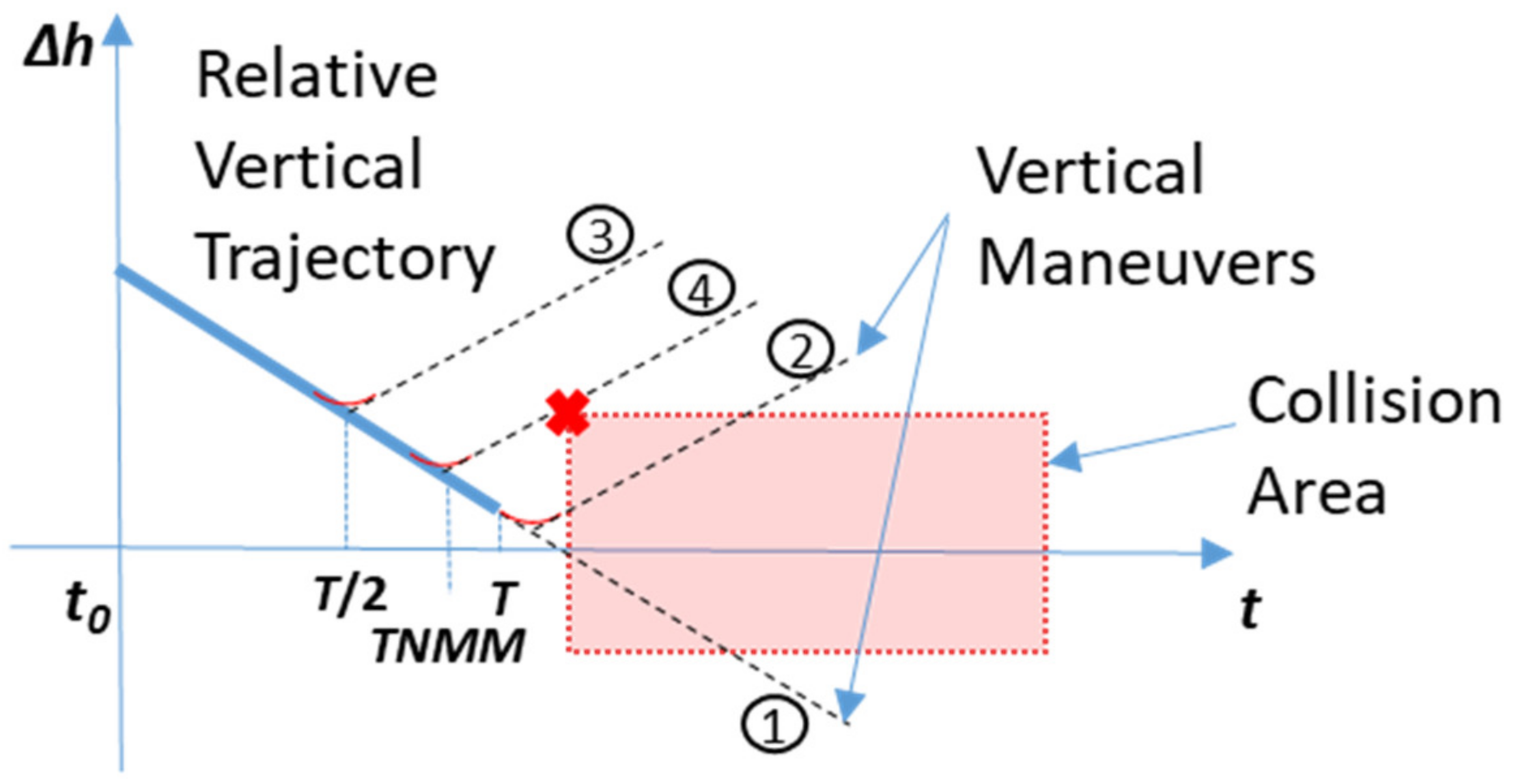
TNMM for vertical maneuvers can be estimated with an iterative process that considers the relative altitude variation and a constant (worst case) on set time (see
Section 5.1). The process is depicted in
Figure 10, where a finite number of
RPr evaluations are performed using a bisection search technique.
After the evaluation of
TNMM for each single intruder, the combined overall
TNMM can be computed as follows:
where
i is the index in the set 1…
N intruders and
is the index associated to the minimum value of the
TNMM computed for a single intruder. Equation (22) relates the single intruder’s
TNMMs to the overall
TNMM at
tk. Indeed, using the ratio between the
MM of the worst intruder and the global
MM is a way to take into account how much the other intruders (and fixed obstacles) contribute to reducing the final
TNMM. Indeed, finding the
TNMM when more than one threat is contributing to the
MM reduction is a tricky problem that can be very computationally intensive. Relations different from Equation (22) or other methods can be adopted, given that they are computationally affordable and prove to be sufficiently accurate. To overcome this major limitation of the algorithm, some future improvements could include using artificial intelligence techniques directly on the
ORPr functions so as to predict the possible scenario evolution based on experience, as humans normally do.
Having computed
MM and
TNMM at the current time step, we have all the elements necessary to take an automatic decision. The proposed decision-making process is basically implemented as a discrete state machine with heuristic rules for state transitions (see
Figure 11).
The states and transitions in such decision making logic are as follows:
No Threats corresponds to no imminent potential collision.
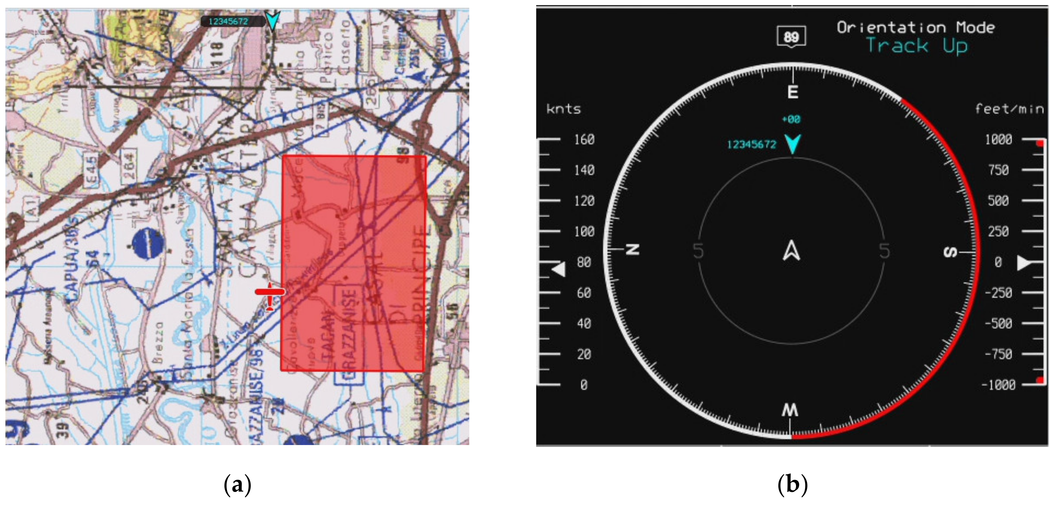
Monitor Threats indicates that at least one potential collision is detected, not considering any maneuver (i.e., the RPr is below the threshold for the predicted intruder and ownship trajectories). This is a pre-alert status that is basically introduced to inform the pilot through the ground station display that a potential conflict has been detected.
Turn Right/Left, Climb, Descend correspond to raising a collision warning alert and executing the respective maneuver. Only one of these states is accessed when MM or TNMM is below given thresholds (to be tuned). The type of avoidance maneuver is selected after performing several considerations, as better described below. During the maneuver execution, and until a safe situation is restored, the algorithm continuously evaluates the situation to check whether the current avoidance maneuver is still safe.
Change Maneuver is accessed if the current avoidance maneuver type is no longer safe, and a revision of the current maneuver type or command is required.
The process of selecting the type of maneuver and the related command considers the safety of flight, TCAS-II interoperability and Right of Way (RoW) rules, as specified in
Section 2. Therefore, the optimal command computed as per
Section 5.5 is not always used.
When considering multi-intruder scenarios, the most hazardous intruder is selected to comply with TCAS-II interoperability and RoW rules. This intruder is chosen using the following criteria:
- (a)
Presence of a TCAS-II Resolution Advisory from the intruder;
- (b)
Number of maneuver types with a null margin of maneuver;
- (c)
Lower time to a null margin of maneuver;
- (d)
Lower margin of the maneuver.
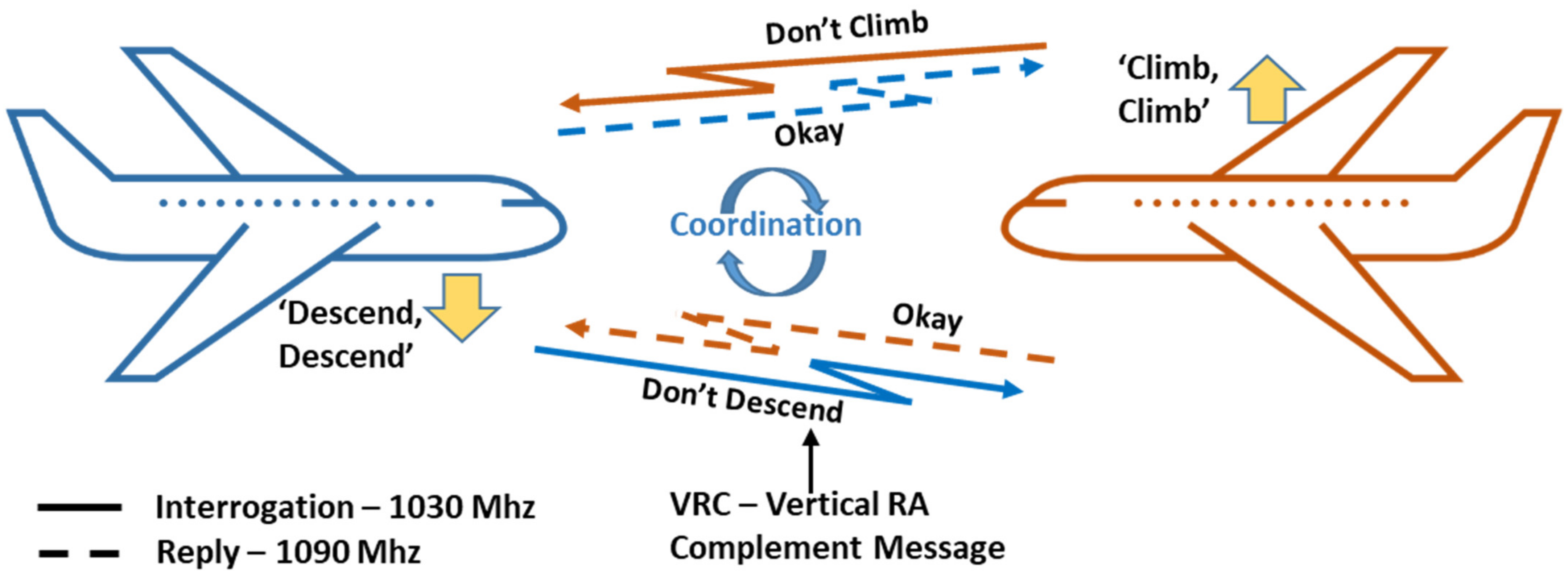
The TCAS-II interoperability implementation is based on the so-called Responsive Coordination. Actually, when an intruder is identified as TCAS-II-equipped, the proposed CDA algorithm complies with the Vertical Resolution Advisory Complement (VRC) provided by the other aircraft [
12], if this has been received from the on-board sensors (see
Figure 12).
In case no VRC has been received or for aircraft not equipped with TCAS-II aircraft, the RoW rules are basically applied using quantitative criteria (with different thresholds), as specified by DAA MOPS, App. H [
5]. The maneuver type suggested by the RoW rules is selected only if it is not detrimental to safety, i.e., the predicted risk level associated to its optimal command is as low as other possible maneuver types.
Otherwise, or when the ownship has RoW, the maneuver type and the related optimal command are chosen as computed in Equation (19).
