2.1. Description of the Hypersonic-Vehicle Fairing Separation Process
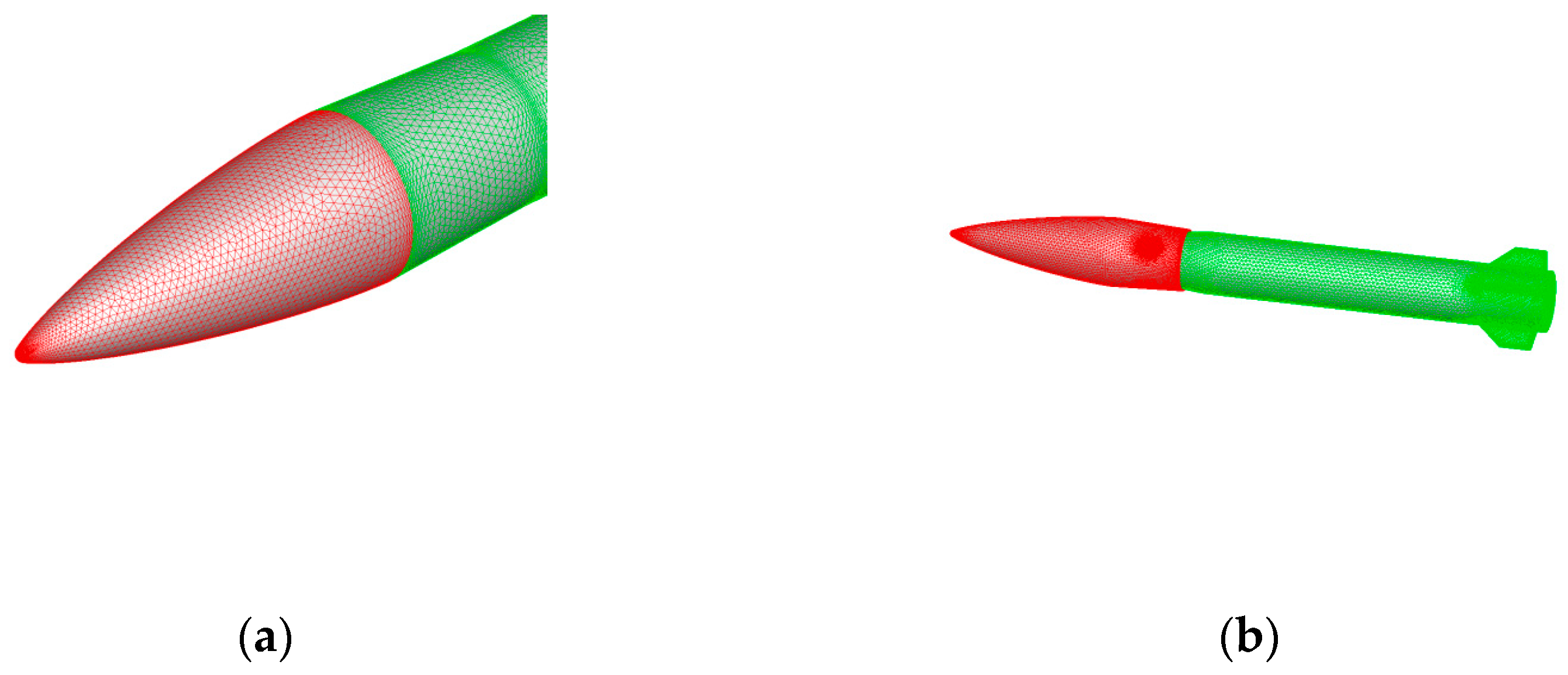
The research object of this paper is a hypersonic vehicle with an integral hood, based on an actual engineering project; an outline diagram is presented in
Figure 1. The aircraft features an axisymmetric shape, with an integral hood at the front.
Fairing separation adopts integral forward pushing and side pushing. The initial velocity of the hood at separation is 5.6 Ma. The separation process is as follows:
: A command is sent to separate the fairing. The explosive bolt detonates and the fairing disconnects from the aircraft;
: The forward-pushing engine on the fairing ignites, which impels the fairing to move forward along the slideway until the cover body completely disengages from the aircraft;
: The fairing moves forward until it reaches a safe distance, and there is no airflow interference between the fairing and the aircraft. The aerodynamic interference of the fairing movement process on the aircraft changes from strong to weak;
: The fairing slideway pushes the engine to work. It moves laterally ahead of the aircraft to prevent a collision.
The fairing-separation process is shown in
Figure 2.
In the process of fairing separation in hypersonic vehicles, there is a very complex aerodynamic-interference field. In this study, the trajectory and force of the hypersonic-vehicle fairing-separation process were simulated by a CFD method based on overlapping-grid technology. The CFD tool used in this paper is developed by China Aerodynamics Research and Development Center. The software can simulate the application scenarios of aircraft, helicopters, missiles, reentry vehicles, and other aircraft with low speed, subsonic, transonic, supersonic, and hypersonic speed, such as steady and unsteady aerodynamic forces, multibody motion, inlet internal flow, jet-flow field, and so on. The software is characterized by multibody motion simulation and covers typical CFD processes such as grid processing, numerical solution, and engineering data processing.
The calculation process was:
Generating the initial grid, including the background grid of the aircraft with booster stage before package separation and the subgrid of the aircraft;
Automatic hole digging: perform automatic hole digging on the background grid and subgrid, judge whether the grid is in the calculation area, and build the overlapping relationship between them so as to establish the interpolation data structure in the calculation process;
Flow-field solution: for the established overlapping grid, the flow-field solver is used to calculate and obtain the convergent aerodynamic characteristics;
Solution to the 6DOF equation: calculate the velocity, position, and attitude by using the calculated aerodynamic force and torque;
According to the obtained speed, position, and attitude, the mesh is moved and rotated. At the same time, judge whether the separated object collides with the carrier. If it collides, exit the calculation;
Repeat steps b to e until the aircraft is separated to a safe distance.
The numerical simulation method for analyzing aircraft aerodynamic characteristics mainly includes unsteady calculation, control equation, discretization, and boundary conditions. The unsteady method is used to calculate the aerodynamic interference in the separation process of hypersonic vehicles, and its control equation is:
where
is the conserved variable vector,
is the inviscid flux vector,
is the viscous flux vector,
is the velocity of the face
, and
is the normal vector of the face
.
The governing equation in the unit body is obtained by integrating the equation:
where
is the unit volume,
is the unit external normal vector of the unit surface,
is the total number of surfaces of the unit (
),
is the area of the surface
, and
and
are the normal inviscid and viscous flux of the surface
.
The velocity of the element surface can be obtained directly from the coordinates of the face-center coordinates in the time layer and the time layer , which is .
Let
; then
where
= 0 is the first-order accuracy of time and
= 1/2 is the second-order accuracy of time. Double time stepping, also known as pseudo-time sub-iteration,
, is used to solve the equation. Thus, the virtual time step term
is directly added to the equation, and the equation becomes:
The steady solution of the equation is obtained by the step-by-step solution of the virtual time step is ; then, it can be used to continue the solution of the next time step .
For the steady solution of the equation, the LU-SGS method is adopted for time discretization, and the following can be obtained:
where
is the spectral radius
The roe flux-differential splitting method is used for inviscid flux, Venkat is used for the limiter, and the center format is used for viscous term. Due to the long work cycle of unsteady calculations, local time steps and multigrid techniques are also used in the subiteration to improve the calculation efficiency. The turbulence model is a one-equation SA model. The multigrid technology used in this paper is based the “direct-cutting” strategy. This method does not need assistant mesh and has excellent robustness. The core algorithm of the multigrid technology includes overlapping assembling and overlapping interpolation. The purpose of overlapping assembling is to define the attributes of mesh elements, including active elements, interpolation elements, and inactive elements. Overlapping interpolation needs to search for the contributing unit corresponding to the unit to be interpolated, then transfer the flow field between grids through the trilinear interpolation method. The ADT method is used while searching for the contribution unit to accelerate the algorithm. The grid moves synchronously with the separation body, which is divided into translation and rotation. The translation part is coordinate displacement, and the rotation part constructs the rotation matrix through the attitude angle.
The main calculative parameters are as follows:
Mach number, 5.6; altitude, 21 km; angle of attack, 5.0°; sideslip angle, 0.0°.
Courant–Friedrichs–Lewy (CFL) number, 0.8; number of steps, 2000; number of multigrid layers, 5;
The CFD calculation adopts high-performance computing-cluster 64-core parallel computing, the turbulence model adopts the SA equation, the spatial discrete format adopts the roe format, and the time advance adopts the implicit two-step time method.
The six-degrees-of-freedom calculation was conducted from 0.0 s to 0.24 s of the time node, and the grid was automatically divided every 20 ms to divide the fairing separation process into 12 stages. Therefore, after the relative displacement between the fairing and aircraft, the grid needs to be updated every 20 ms to adapt to the subsequent flow simulation. Moreover, the initial relative speed of the fairing to the aircraft is 0. The number of steps, 2000, means that for each inner iteration the time for performing a steady calculation is about 6 h, whereas the time for performing an unsteady calculation is about 65 h. When the aerodynamic values tend to be stable, the results are considered to converge.
Overlapping-grid technology is key in hypersonic multibody separation simulations. In order to realize the accurate simulation of relative motion between multibodies, corresponding grids are generated for different objects, and the flow-field information is transmitted between different grids through interpolation technology. Overlapping-grid technology mainly includes overlapping hole excavation, contribution element search and flow field interpolation.
In this study, the “object-surface intersection” direct hole-digging method was adopted, which has high robustness and can easily be extended to dig holes between multiple sets of meshes. In terms of contribution-unit searches, at each time step, the alternative digital tree (ADT) method is used to find the corresponding relationship between all nodes of background grid A and subgrid B control units, and search for the contribution unit of the unit to be interpolated. This method arranges the spatial points in order and constructs them into binary tree data, which improves the efficiency of the query. In this study, the control volume was constructed as binary tree data to find the grid nodes in the control volume; trilinear interpolation was used to realize the data transmission between different grids. Trilinear interpolation is commonly used in the finite-element method. Unlike the distance-weight method which only considers the distance, trilinear interpolation regards the flow field as a continuous linear distribution in the contribution element, and performs a linear interpolation along three directions of space. Trilinear interpolation can ensure the continuity of the interpolation of the elements on both sides on the interface of the two elements, i.e., the values of the points on the interface are the same based on the interpolation of the elements on both sides, so as to avoid interpolation discontinuities near the interface [
11]. Zhang et al. studied the aerodynamic characteristics of grid rudder by numerical simulation. Through the comparison of the aerodynamic characteristics of grids with different shapes, the design scheme with better aerodynamic characteristics and structural strength is given [
12].
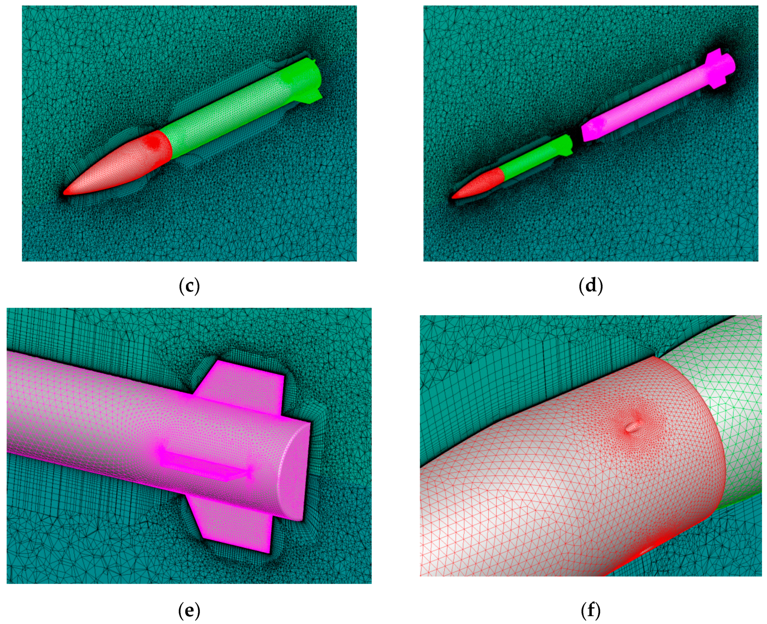
In order to solve the N-S equation numerically, the mesh generation must be carried out. In this study, the unstructured grid element mixed with triangular prism and tetrahedron was adopted, as was the idea of three-level grid generation. In the area close to the boundary layer of the object surface, the triangular prism-grid element with a layer structure was adopted to simulate its viscous effect, and the tetrahedral element in the spatial area near the object surface was properly densified to capture its spatial shock wave and vortex structure, The far-field area was filled with smooth-transition tetrahedral elements to meet the far-field requirements of flow-field simulation. The generated typical regional grid is shown in
Figure 3. The total grid consisted of about 13 million elements, including about 5 million triangular prism elements and 8 million tetrahedral elements.
Using the numerical-simulation method established above, aerodynamic-interference simulation of the hypersonic-vehicle fairing-separation process was carried out. The fairing separation was carried out through the fairing engine, which was simulated through the given jet conditions, considering the interference effect of the jet; the total pressure of the jet nozzle was 19 MPa and the thrust was 10 kN.
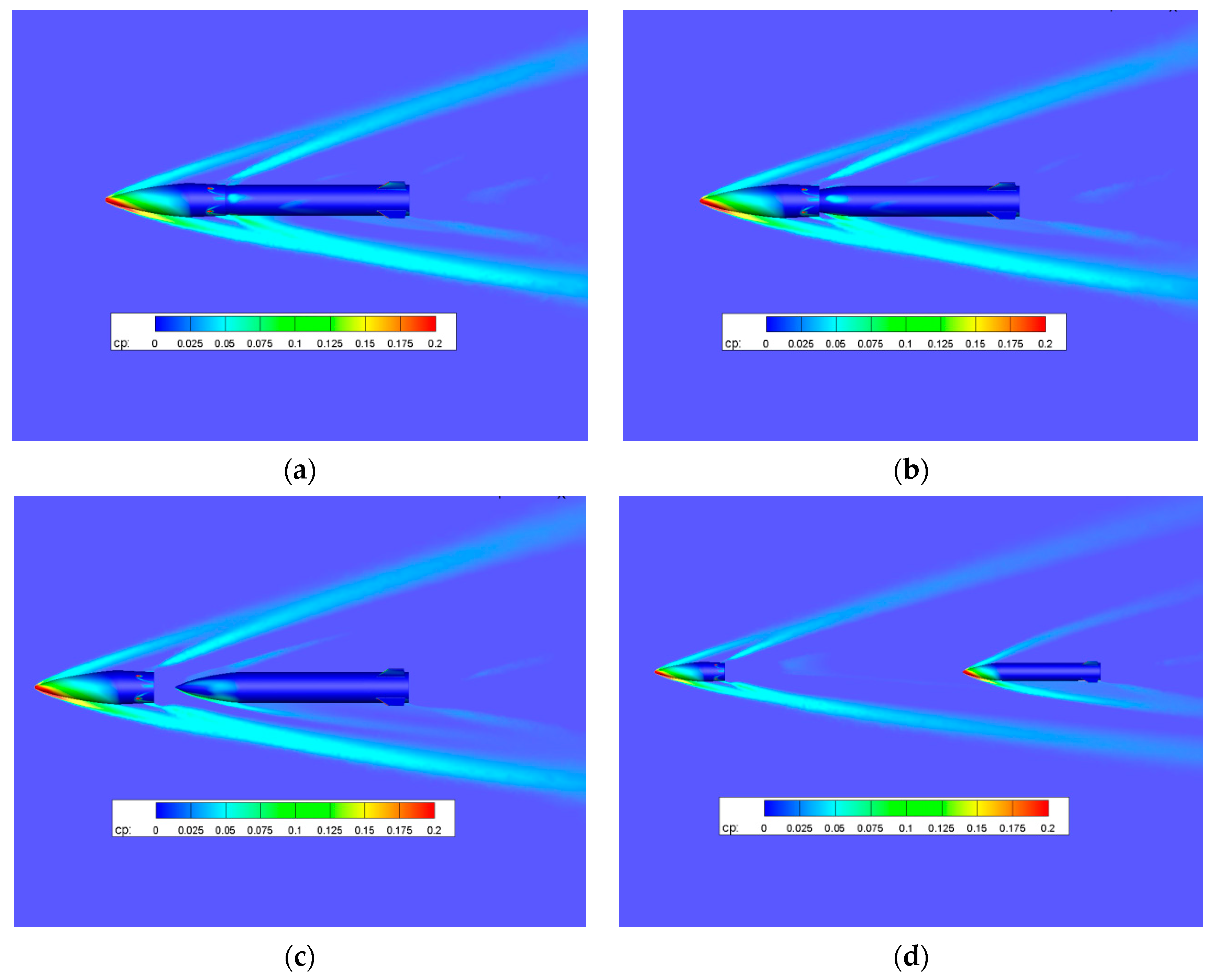
Figure 4 shows the pressure-distribution cloud diagram of the symmetrical plane at different times during the fairing-separation process. It can be seen that during the separation process of the fairing, a strong detached oblique-shock-wave structure is generated at the front end of the hood, resulting in large aerodynamic resistance on the fairing hood. When the fairing is separated from the aircraft, shock waves will also be generated at the front end of the aircraft. However, this magnitude did not interfere with the flow field at first. When the fairing was completely separated from the aircraft, the shock interference at the front end of the aircraft began to become obvious. The forward thrust provided by the jet engine needs to overcome the resistance generated by the head shock wave; the high-pressure gas from the engine jet has a certain effect on the incoming flow, and an obvious separation-shock-wave structure is produced in front of the nozzle. With the increasing distance between the hood and the aircraft, the windward surface of the front end of the aircraft is gradually impacted by the high-pressure air flow, and the shock wave of the aircraft head is gradually enhanced. At around 0.12 s, the rectifier hood and the missile body are mostly pulled out. At 0.22 s, the axial distance between the hood and the aircraft has reached the length of the missile body of the aircraft. At this point, it is essentially safe to separate the head cover from the missile body.
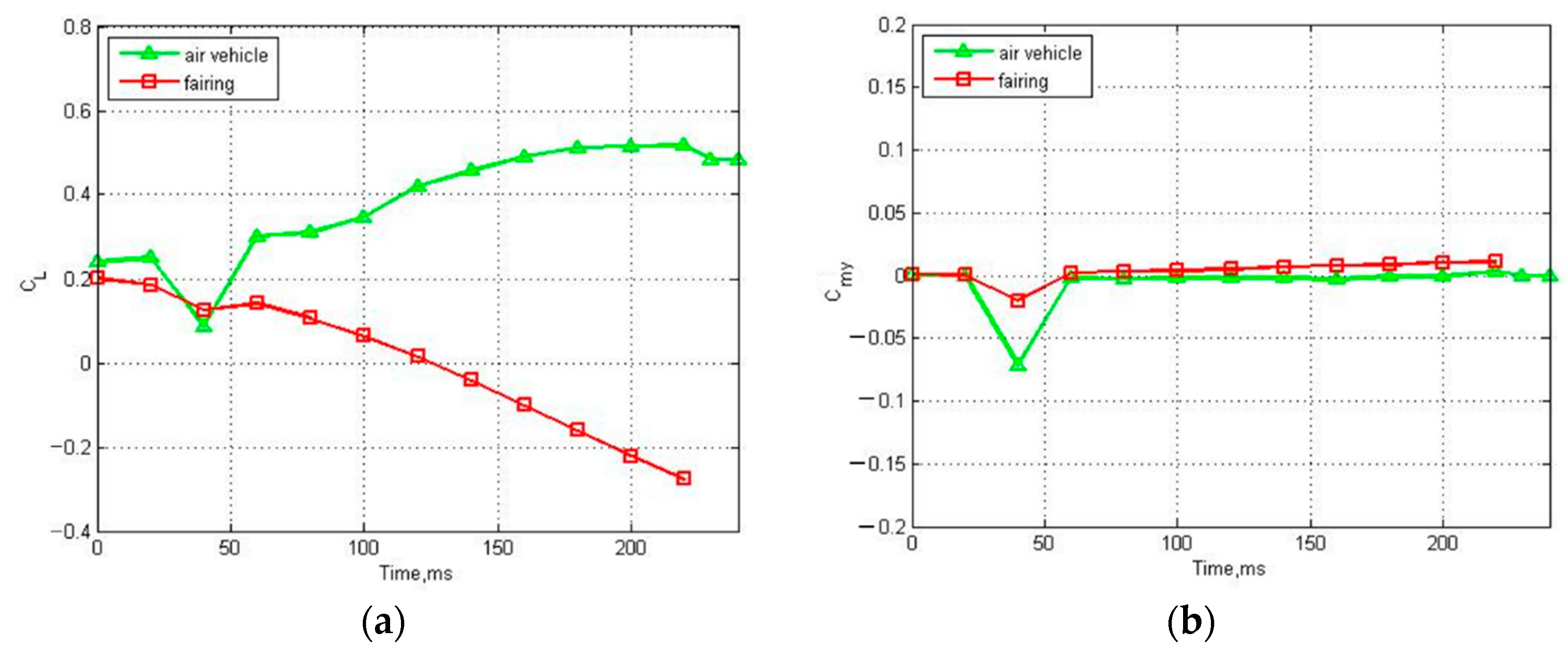
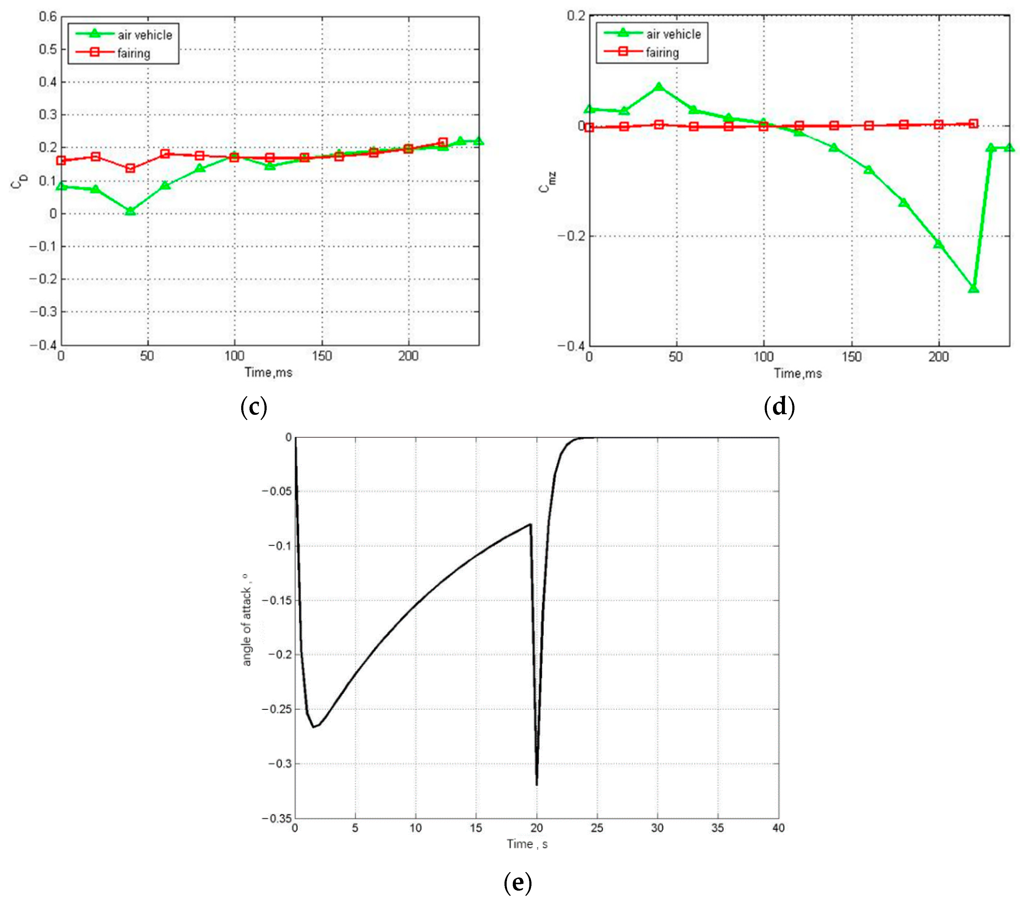
Figure 5 shows the variation curves of the lift, drag, lateral force, and pitching moment coefficients of the verification machine and the fairing during the separation process.
It can clearly be seen from
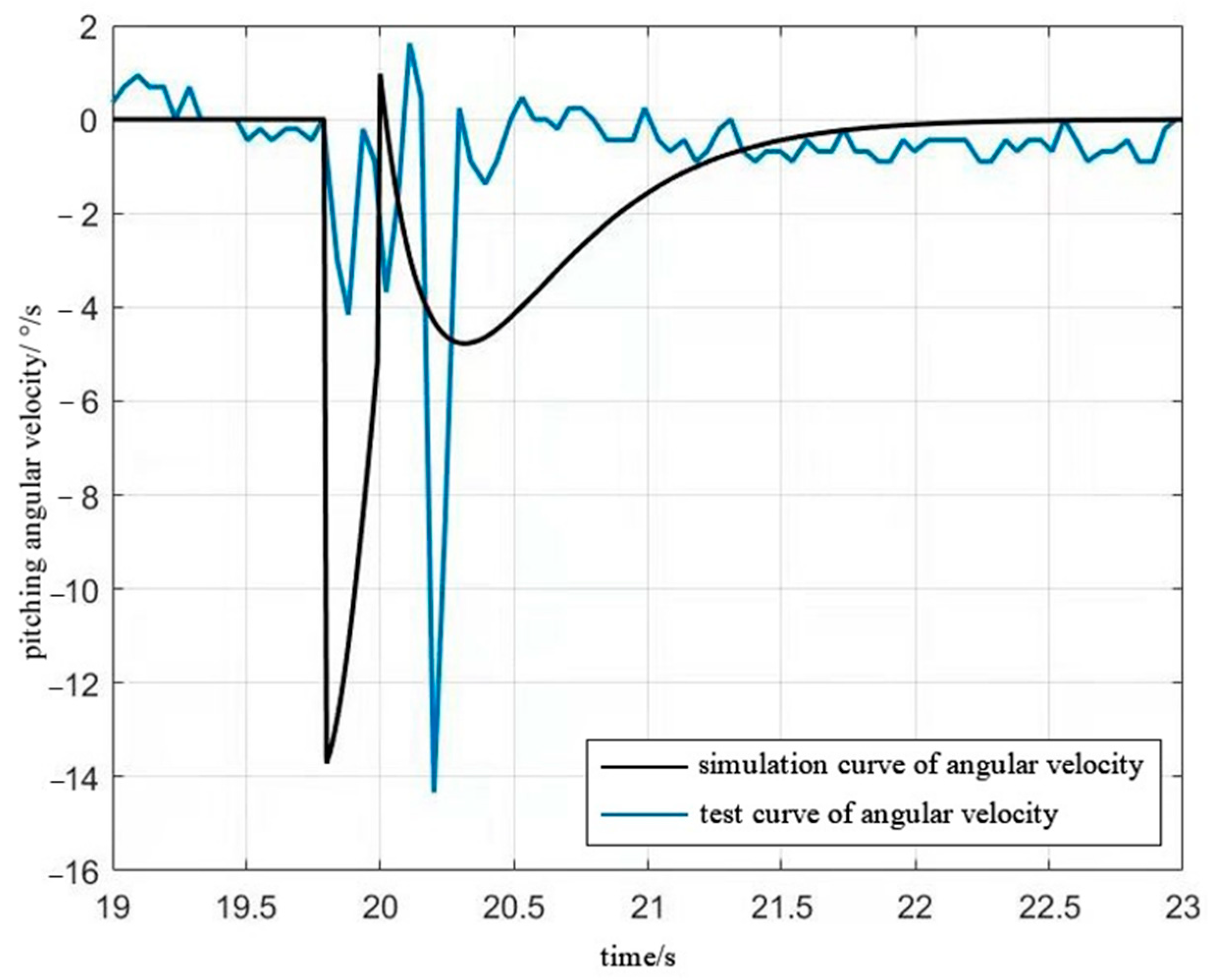
Figure 5 that the fairing has an obvious airflow interference with the aircraft during the separation process. Before the aircraft is completely separated from the fairing, the lift coefficient, drag coefficient, and lateral force coefficient spike, especially between 40 and 70 ms. When the fairing has been separated from the body for a certain distance, affected by the interference of the high-pressure flow field generated by the fairing, the pitching moment coefficient of the aircraft decreases sharply to a negative value, which will exert an anti-manipulation effect on the control effect until the fairing is safely separated from the body. From the
Figure 5d, the curve of the pitching moment coefficient
starts from a positive number when the separation began; along with the separation, the pitching moment coefficient declines to a negative value rapidly. The sign change of the pitching moment coefficient means that the control effect of the tail will also change; that is, if the control strategy before the sign change is continued, the opposite result will appear. From
Figure 5e, it can be seen that the aerodynamic interference generated by fairing separation has a great impact on the angle of attack of the aircraft. The impact is adverse to the attitude stability of the aircraft.


