
Flocking Bird Strikes on Engine Fan Blades and Their Effect on Rotor System: A Numerical Simulation

 ,
,
Abstract
:1. Introduction
2. Bird-Strike and Rotor Dynamics System Modeling
2.1. Bird SPH Model and Validation
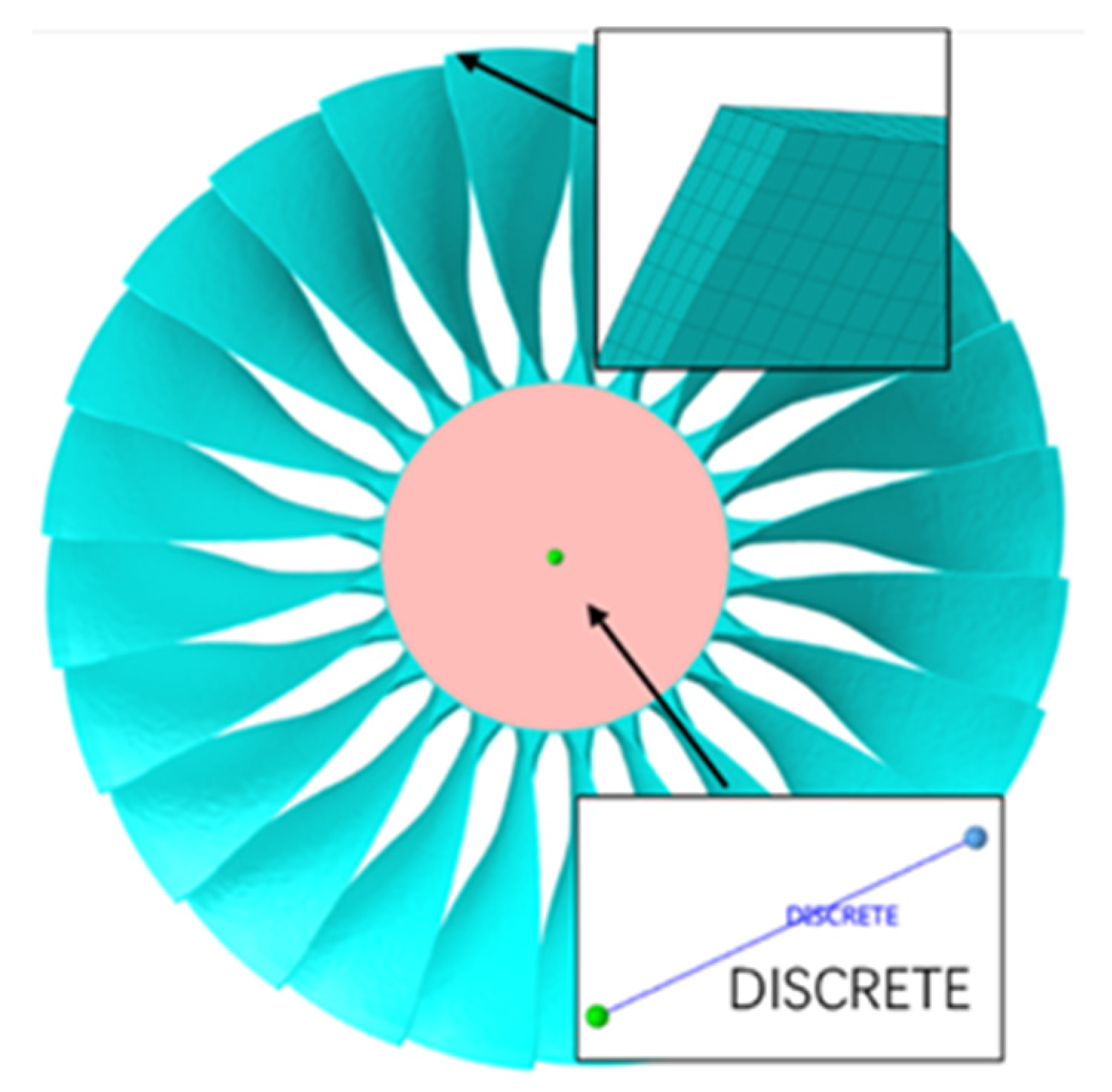
2.2. Fan Modeling
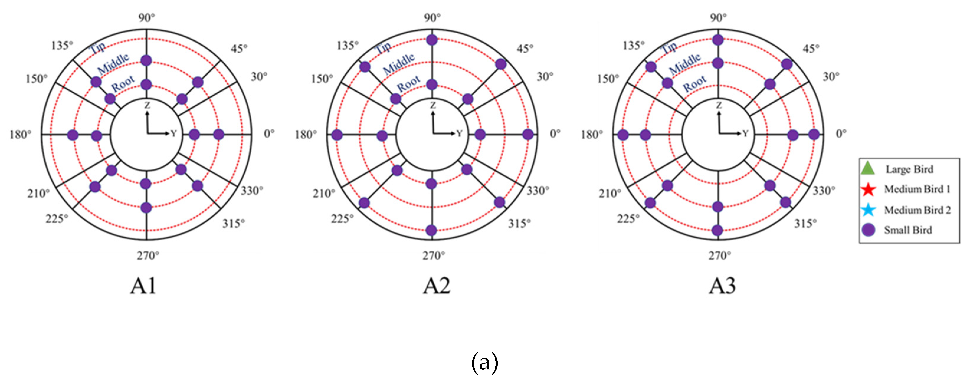
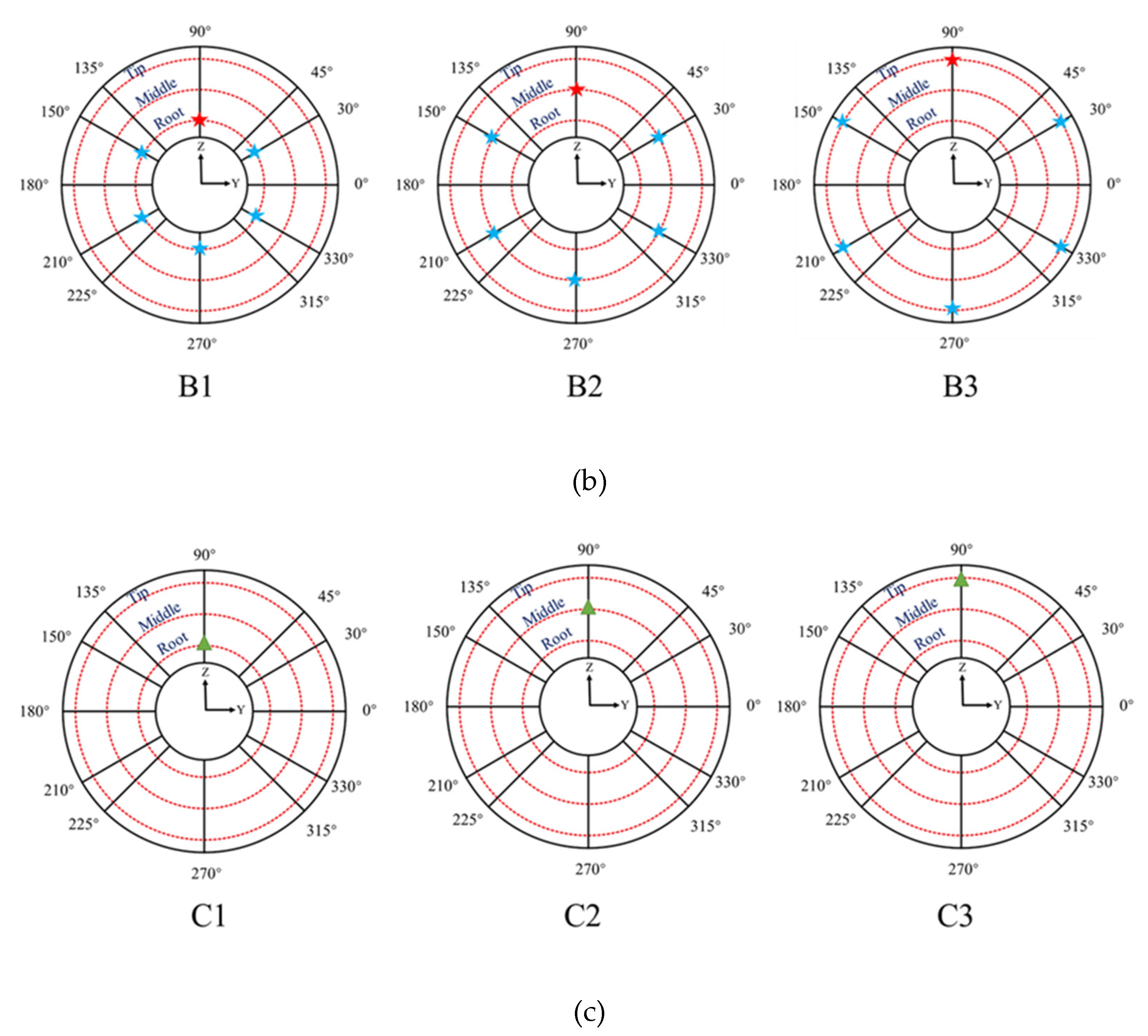
2.3. Bird-Strike Settings
2.4. Prestress Analysis
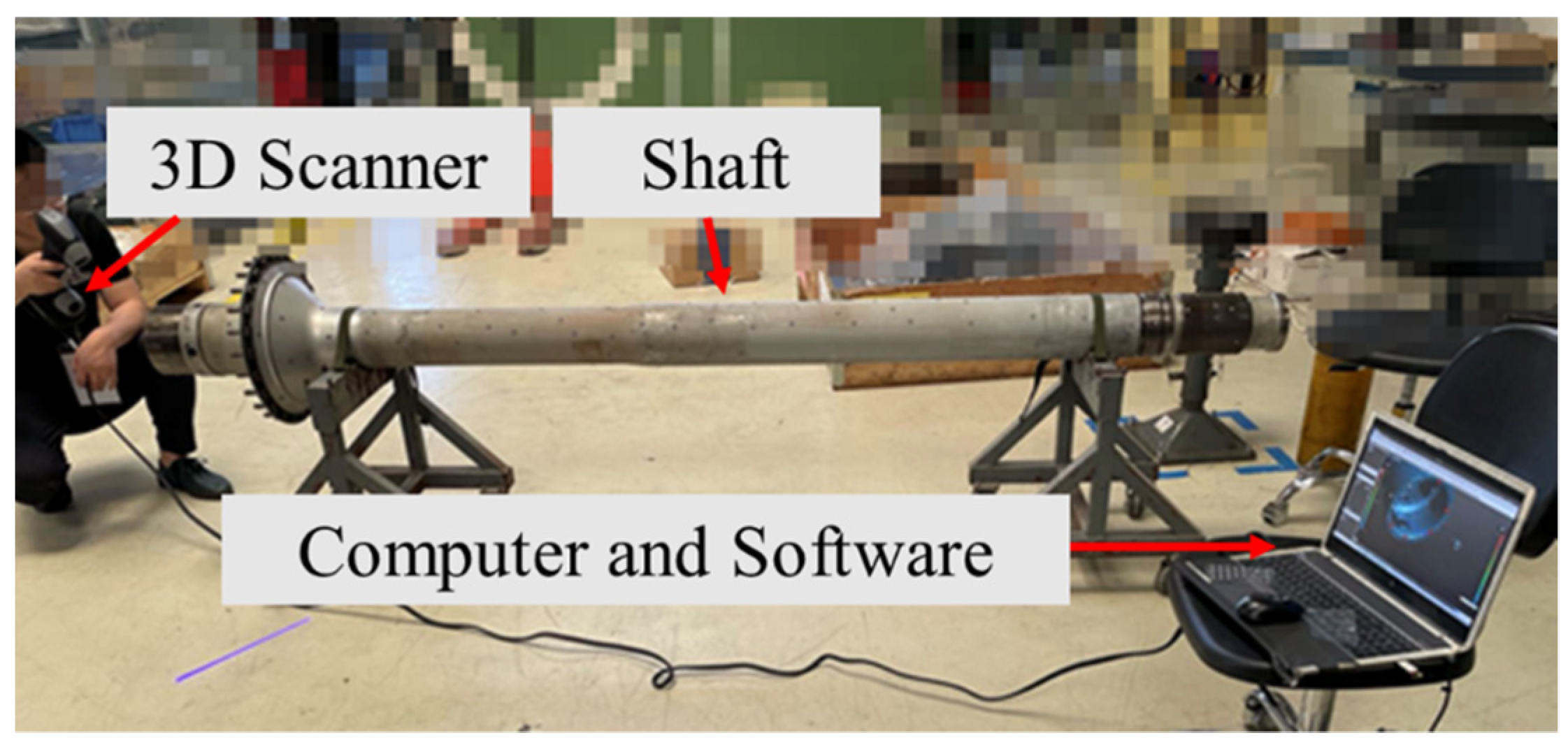
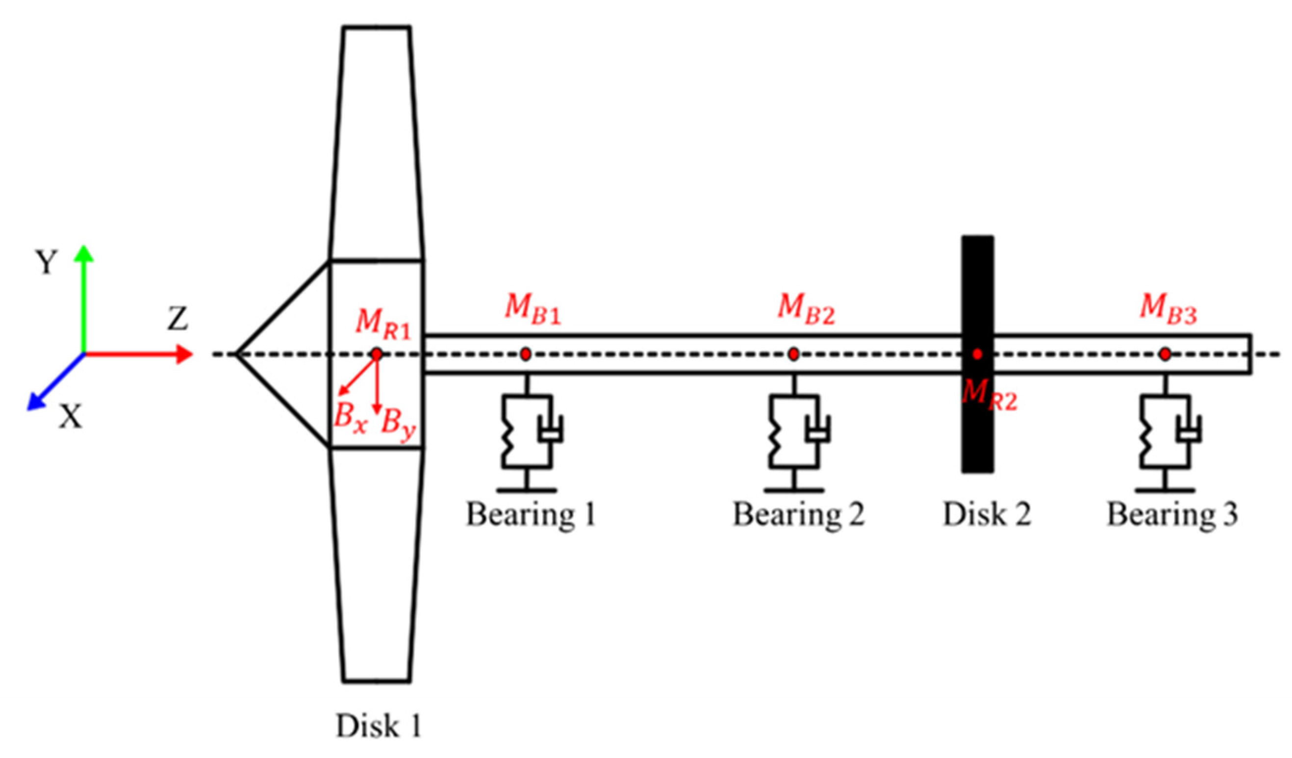
2.5. Aero-Engine Rotor System and Validation
- Consider the fan hub and blades as a disk, and add the bird impact force to this disk;
- The eccentricity of the rotor system existed only on the two simplified rotor disks;
- The connection between blades and disk was ignored, and the shaft and disks were considered to be rigidly connected;
- Gyroscopic effects of the rotor system were not considered due to the low speed of 3772 r/min.
2.6. Dynamic Calculation Settings
3. Results and Discussion
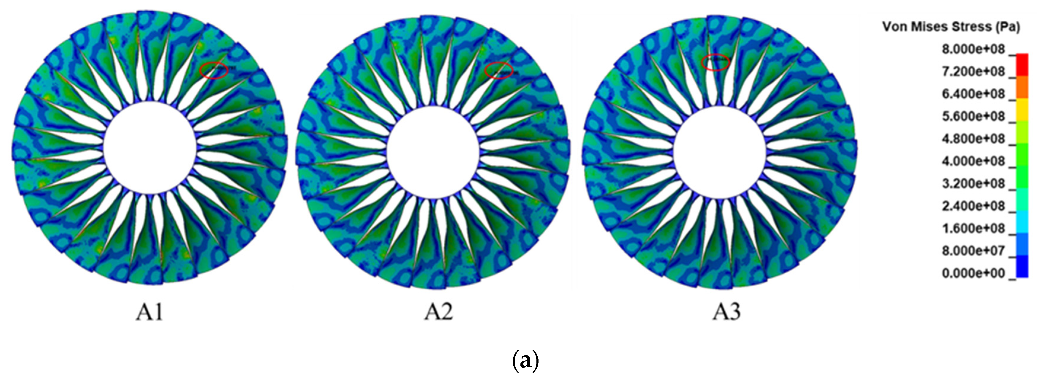
3.1. Bird Strike Simulation
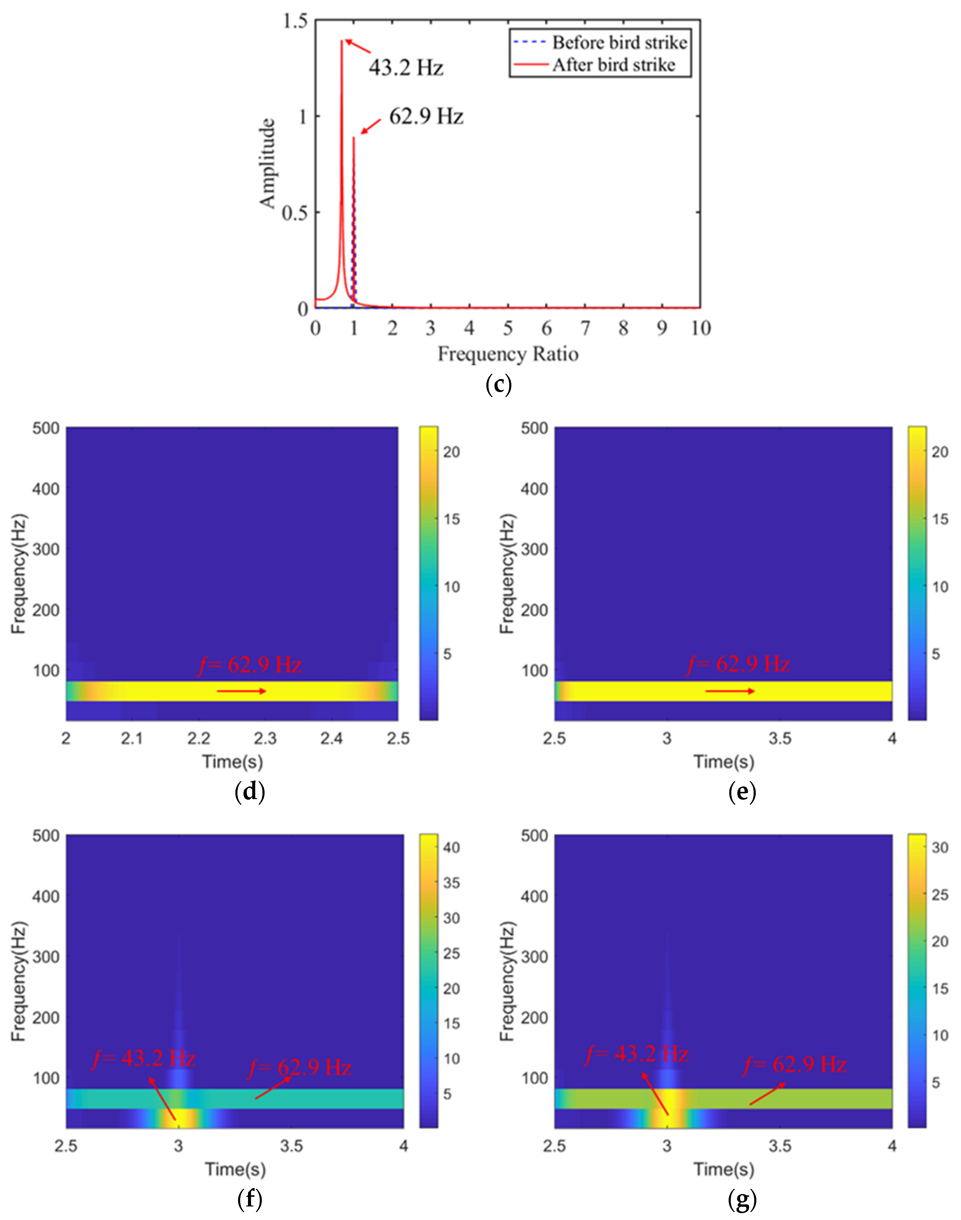
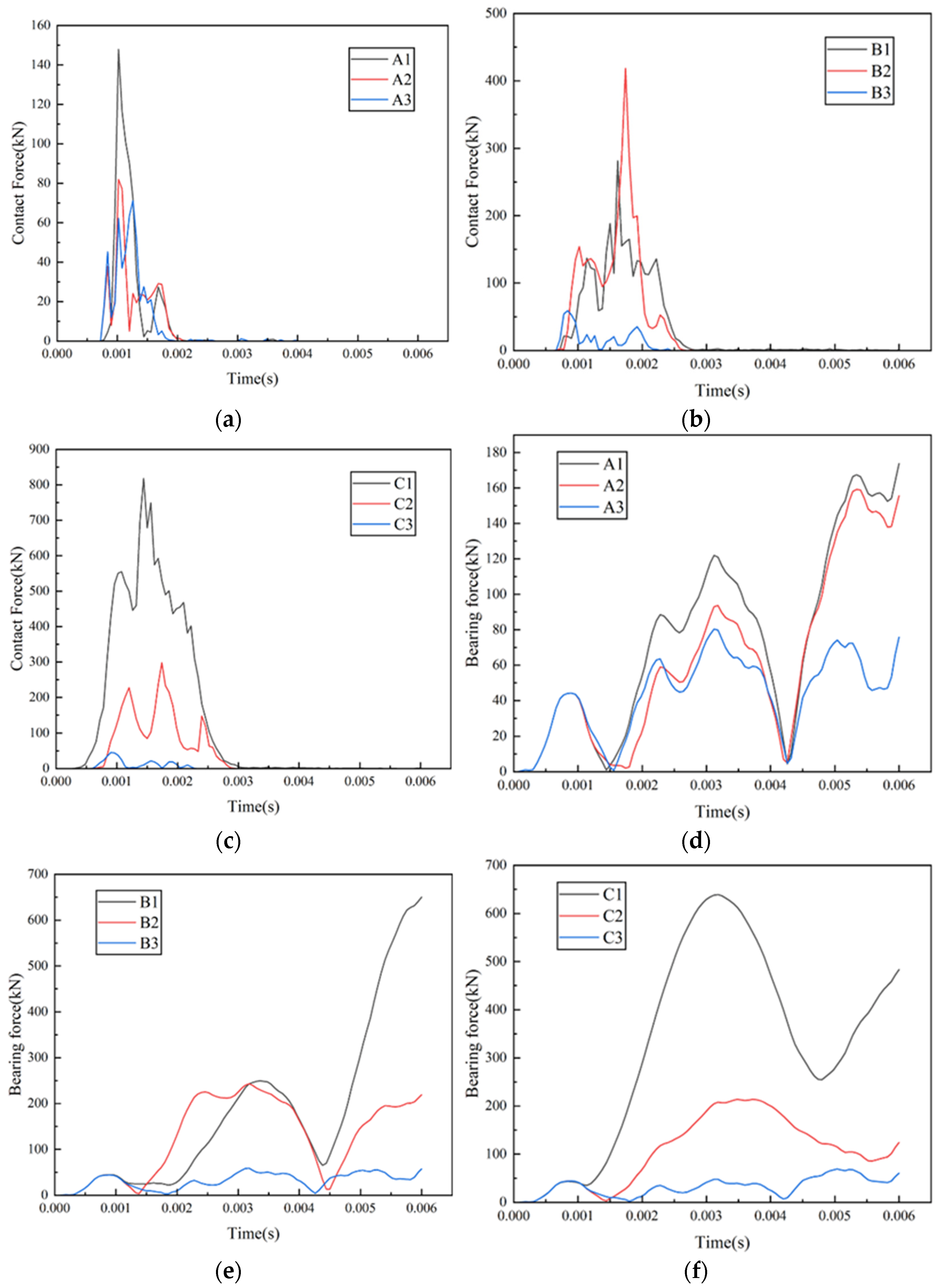
3.2. Rotor System Dynamics Calculation
4. Conclusions
Author Contributions
Funding
Institutional Review Board Statement
Informed Consent Statement
Data Availability Statement
Acknowledgments
Conflicts of Interest
Abbreviations
| Nomenclature | |
| Abbreviation | Definition |
| 3D | Three-Dimensional |
| CT | Computed Tomography |
| EOS | Equation Of State |
| FAA | Federal Aviation Administration |
| FE | Finite Element |
| FEM | Finite Element Method |
| IBRG | International Bird-strike Research Group |
| SPH | Smoothed Particle Hydrodynamics |
| US | United States |
| List of symbols | |
| Symbol | Definition |
| Yield stress | |
| a | First-order volume correction to γ0 |
| Strain hardening modulus | |
| Bird impact forces in the x and y directions | |
| C | The intercept of the velocity curve |
| Damping coefficients of ball bearings | |
| Damping coefficients of the disk | |
| Strain rate dependence coefficient | |
| D | Damage parameter |
| Failure parameters | |
| E | Elastic modulus of material |
| The eccentricity of Disk 1 | |
| The eccentricity of Disk 2 | |
| Rate-of-deformation tensor | |
| Shear modulus | |
| Gravitational acceleration | |
| Stiffness of the shaft | |
| Mass of Disk 1 | |
| Mass of Disk 2 | |
| Mass of Bearing 1 | |
| Mass of Bearing 2 | |
| Mass of Bearing 3 | |
| Softening exponent | |
| Strain hardening exponent | |
| p | Pressure |
| S1, S2, S3 | Slope coefficients of the velocity curve |
| Current temperature | |
| The melt temperature of the material | |
| Room temperature | |
| Homologous temperature | |
| Displacement in the x and y directions | |
| Velocity in the x and y directions | |
| , | Acceleration in the x and y directions |
| Dynamic viscosity coefficient | |
| Gruneisen constant | |
| Clearance of the ball bearing | |
| The density of the material | |
| Reference density | |
| Rotational speed | |
| List of Markings | |
| Symbol | Definition |
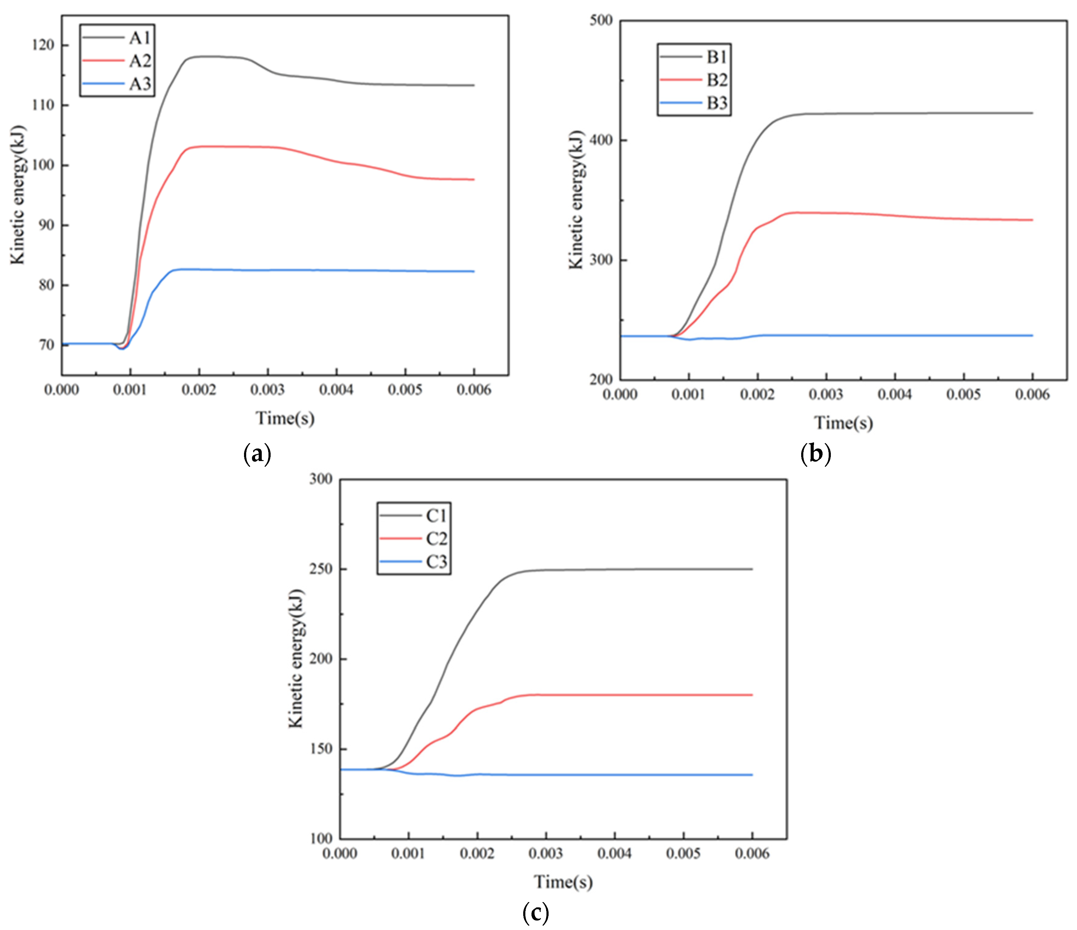
| A1 | Small flocking bird strike on the root and middle of blades |
| A2 | Small flocking bird strike on the root and tip of blades |
| A3 | Small flocking bird strike on the middle and tip of blades |
| B1 | Medium flocking bird strike on the root of blades |
| B2 | Medium flocking bird strike on the middle of blades |
| B3 | Medium flocking bird strike on the tip of blades |
| C1 | Large single bird strikes on the root of blades |
| C2 | Large single bird strikes on the middle of blades |
| C3 | Large single bird strikes on the tip of blades |
References
- Heimbs, S. Computational methods for bird strike simulations: A review. Comput. Struct. 2011, 89, 2093–2112. [Google Scholar] [CrossRef]
- Atkins, E. Emergency Landing Automation Aids: An Evaluation Inspired by US Airways Flight 1549. In Proceedings of the AIAA Infotech@Aerospace, Atlanta, GA, USA, 20–22 April 2010. [Google Scholar]
- Regulation, F.A. Part 33, Airworthiness Standards: Aircraft Engines. Federal Avia 2011, 332–371. Available online: https://www.law.cornell.edu/cfr/text/14/part-33.
- Budgey, R. Three dimensional bird flock structure and its implications for birdstrike tolerence in aircraft. Proc. Int. Bird Strike Comm. 1999, 24, 307–320. Available online: https://canadianbirdstrike.ca/wp-content/uploads/2018/02/Budgey_1998.pdf.
- Cai, J.; Bao, H.; Zuo, H.; Huang, Y. Safety evaluation of airworthiness requirement of bird-strike on aeroplane. Eng. Fail. Anal. 2019, 102, 407–416. [Google Scholar] [CrossRef]
- El-Sayed, A.F. Bird strike in Aviation: Statistics, Analysis and Management; John Wiley & Sons: New York, NY, USA, 2019. [Google Scholar]
- Budgey, R. The development of a substitute artificial bird by the international Bird strike Research Group for use in aircraft component testing. International Bird Strike Committee ISBC25/WP-IE3, Amsterdam. In Proceedings of the International Bird Strike Committee, Amsterdam, The Netherlands, 17–21 April 2000. [Google Scholar]
- Hedayati, R.; Ziaei-Rad, S. Effect of bird geometry and orientation on bird-target impact analysis using SPH method. Int. J. Crashworthiness 2012, 17, 445–459. [Google Scholar] [CrossRef]
- Smojver, I.; Ivančević, D. Numerical simulation of bird strike damage prediction in airplane flap structure. Compos. Struct. 2010, 92, 2016–2026. [Google Scholar] [CrossRef]
- Chandra, C.; Wong, T.Y.; Bayandor, J. Crashworthiness assessment in aircraft ditching incidents. In Proceedings of the 27th international congress of the aeronautical sciences, Nice, France, 19–24 September 2010. [Google Scholar]
- Zhang, D.; Fei, Q. Effect of bird geometry and impact orientation in bird striking on a rotary jet-engine fan analysis using SPH method. Aerosp Sci Technol 2016, 54, 320–329. [Google Scholar] [CrossRef]
- Hedayati, R.; Sadighi, M. Bird Strike: An Experimental, Theoretical and Numerical Investigation; Woodhead Publishing: Sawston, UK, 2015. [Google Scholar]
- Puneeth, M.; JayaPrakash, D. Influence of bird mass and impact height on the fan-blade of an aero-engine. Mater. Today Proc. 2021, 44, 1028–1038. [Google Scholar] [CrossRef]
- Vignjevic, R.; Orłowski, M.; De Vuyst, T.; Campbell, J.C. A parametric study of bird strike on engine blades. Int. J. Impact Eng. 2013, 60, 44–57. [Google Scholar] [CrossRef]
- Husainie, S.N. Bird Strike and Novel Design of Fan Blades. In Proceedings of the 2017 Science in the Age of Experience, Chicago, IL, USA, 15–18 May 2017. [Google Scholar]
- Sun, Y.; Zhang, Y.; Zhou, Y.; Zhang, H.; Yang, K. Evaluating Impact Damage of Flat Composite Plate for Surrogate Bird-Strike Testing of Aeroengine Fan Blade. J. Compos. Sci. 2021, 5, 171. [Google Scholar] [CrossRef]
- Sinha, S.K. 5th International LS-DYNA Users Conference Transient Dynamics of Slicing-Impact Loading on Jet Engine Fan Blades during a Bird-strike Event. In Proceedings of the LSDYNA International Conference, Detroit, MI, USA, 10–12 June 2018. [Google Scholar]
- Allaeys, F.; Luyckx, G.; Paepegem, W.V.; Degrieck, J. Characterization of real and substitute birds through experimental and numerical analysis of momentum, average impact force and residual energy in bird strike on three rigid targets: A flat plate, a wedge and a splitter. Int. J. Impact Eng. 2017, 99, 1–13. [Google Scholar] [CrossRef] [Green Version]
- Shahimi, S.S.; Abdullah, N.A.; Hrairi, M.; Ahmad, M.I.B.M. Numerical Investigation on the Damage of Whirling Engine Blades Subjected to Bird Strike Impact *. J. Aeronaut. Astronaut. Aviat. Ser. A 2021, 53, 193–199. [Google Scholar]
- Ritt, S.A.; Johnson, A.F.; Voggenreiter, H. Analysis of Bird Strike under Blunt and Splitting Impact. In Proceedings of the Aerospace Structural Impact Dynamics International Conference (ASIDIC), Wichita, KS, USA, 17–19 October 2017. [Google Scholar]
- Fu, L.; Zhang, J.; Hu, Z.; Zhang, M.; Guo, Y. Numerical Analysis of Bird Impact on an Aluminum Alloy Plate. In Proceedings of the Postdoctoral Symposium of China on Materials Science & Engineering-advanced Materials for Sustainable Development, Shanghai, China, 19 October 2012. [Google Scholar]
- Wu, B.; Lin, J.; Hedayati, R.; Zhang, G.; Zhang, J.; Zhang, L. Dynamic responses of the aero-engine rotor system to bird strike on fan blades at different rotational speeds. Appl. Sci. 2021, 11, 8883. [Google Scholar] [CrossRef]
- Wu, T.; Wang, L.; Wu, L.; Su, S. Transient Response of Flexible Supported Rotor under Airflow Excitation. At. Energy Sci. Technol. 2019, 53, 563–568. [Google Scholar]
- Gao, P.; Hou, L.; Yang, R.; Chen, Y. Local defect modelling and nonlinear dynamic analysis for the inter-shaft bearing in a dual-rotor system. Appl. Math. Model. 2019, 68, 29–47. [Google Scholar] [CrossRef]
- Ma, H.; Yin, F.; Wu, Z.; Tai, X.; Wen, B. Nonlinear vibration response analysis of a rotor-blade system with blade-tip rubbing. Nonlinear Dyn. 2016, 84, 1225–1258. [Google Scholar] [CrossRef]
- Zhu, S.H.; Tong, M.B.; Peng, G.; Kun, X.U. Experimental Study of a Full-Scale Aircraft Windshield Subjected to Bird Impact. J. Exp. Mech. 2009, 24, 61–66. [Google Scholar]
- Manual, L.-D.K.U.s. Volume II. US Army Engineer Waterways Experiment Station, Coastal and Hydraulics Laboratory; Coastal and Hydraulics Laboratory (U.S. Army Engineer Waterways Experiment Station): Vicksburg, MS, USA, 1998. [Google Scholar]
- Wilbeck, J.S. Impact Behavior of Low Strength Projectiles; Texas A&M University: College Station, TX, USA, 1977. [Google Scholar]
- Moakhar, S.; Hentati, H.; Barkallah, M.; Louati, J.; Haddar, M. Parametric study of aluminum bar shearing using Johnson-Cook material modeling. Proc. Inst. Mech. Eng. Part B: J. Eng. Manuf. 2021, 235, 1399–1411. [Google Scholar] [CrossRef]
- Eren, Z.; Tataroglu, S.; Balkan, D.; Mecitoglu, Z. Modeling of Bird Strike on a Composite Helicopter Rotor Blade. In Proceedings of the 58th AIAA/ASCE/AHS/ASC Structures, Structural Dynamics, and Materials Conference, Grapevine, TX, USA, 9–13 January 2017. [Google Scholar]
- Duckitt, S.; Bisagni, C.; Shahpar, S. Parametric bird strike study of A transonic rotor using isogeometric analysis. In Proceedings of the ASME Turbo Expo 2016: Turbomachinery Technical Conference & Exposition, Seoul, Korea, 13–17 June 2016. [Google Scholar]
- Ding, K.; Wang, Z.; Lu, X.; Zhang, J.; Ma, L. Vibration investigation of rotor system with unbalance and blade-casing rubbing coupling faults. J. Vibroengineering 2020, 22, 353–365. [Google Scholar] [CrossRef]


| Categories | Bird Quantity | Bird Weight (kg) | d (mm) | SPH Particles |
|---|---|---|---|---|
| Large bird | 1 | 2.75 | 130.8 | 36,755 |
| Medium bird | 1 | 1.15 | 97.8 | 15,215 |
| +5 | 0.7 | 82.9 | 9404 | |
| Small bird | 16 | 0.085 | 41 | 1111 |
| Parameter | Symbol |
|---|---|
| Density | |
| Shear modulus | |
| Yield stress | |
| Strain hardening modulus | |
| Strain hardening exponent | |
| Strain rate dependence coefficient | |
| Softening exponent | |
| Melting temperature | |
| Room temperature | |
| Specific heat | |
| Failure parameters | |
| Symbol | Definition | Value |
|---|---|---|
| Bird impact forces in the x and y directions | / | |
| Damping coefficients of ball bearings | ||
| Damping coefficients of the disk | ||
| The eccentricity of Disk 1 | ||
| The eccentricity of Disk 2 | ||
| Gravitational acceleration | ||
| Stiffness of the shaft | ||
| Mass of Disk 1 | ||
| Mass of Disk 2 | ||
| Mass of Bearing 1 | ||
| Mass of Bearing 2 | ||
| Mass of Bearing 3 | ||
| Displacement in the x and y directions | / | |
| Velocity in the x and y directions | / | |
| , | Acceleration in the x and y directions | / |
| Rotational speed |
Publisher’s Note: MDPI stays neutral with regard to jurisdictional claims in published maps and institutional affiliations. |
© 2022 by the authors. Licensee MDPI, Basel, Switzerland. This article is an open access article distributed under the terms and conditions of the Creative Commons Attribution (CC BY) license (https://creativecommons.org/licenses/by/4.0/).
Share and Cite
Wu, B.; Lin, J.; Xie, A.; Wang, N.; Zhang, G.; Zhang, J.; Dai, H. Flocking Bird Strikes on Engine Fan Blades and Their Effect on Rotor System: A Numerical Simulation. Aerospace 2022, 9, 90. https://doi.org/10.3390/aerospace9020090
Wu B, Lin J, Xie A, Wang N, Zhang G, Zhang J, Dai H. Flocking Bird Strikes on Engine Fan Blades and Their Effect on Rotor System: A Numerical Simulation. Aerospace. 2022; 9(2):90. https://doi.org/10.3390/aerospace9020090
Chicago/Turabian StyleWu, Bin, Jiewei Lin, Anshun Xie, Ning Wang, Guichang Zhang, Junhong Zhang, and Huwei Dai. 2022. "Flocking Bird Strikes on Engine Fan Blades and Their Effect on Rotor System: A Numerical Simulation" Aerospace 9, no. 2: 90. https://doi.org/10.3390/aerospace9020090
APA StyleWu, B., Lin, J., Xie, A., Wang, N., Zhang, G., Zhang, J., & Dai, H. (2022). Flocking Bird Strikes on Engine Fan Blades and Their Effect on Rotor System: A Numerical Simulation. Aerospace, 9(2), 90. https://doi.org/10.3390/aerospace9020090