Article

Investigation on a Flow Coupling Rudder for Directional Control of a Low-Aspect Tailless Configuration with Diamond-Shaped Wing

School of Aeronautics, Northwestern Polytechnical University, Xi’an 710072, China
*
Authors to whom correspondence should be addressed.
Aerospace 2022, 9(2), 79; https://doi.org/10.3390/aerospace9020079
Submission received: 21 December 2021 / Revised: 23 January 2022 / Accepted: 29 January 2022 / Published: 1 February 2022
(This article belongs to the Section Aeronautics)

Abstract

:
To solve the issues of directional control and aerodynamic moment coupling for a low-aspect tailless configuration with a diamond-shaped wing, we herein propose the concept of a flow coupling rudder (FCR). The FCR was composed of two basic control surfaces: a spoiler slot deflector (SSD) on the upper surface of the wing and the corresponding elevon. With the constraints of the fixed area and spanwise position of the SSD, the effects of the leading-edge sweep angle, chord position of the SSD, and collocating deflection angles of the SSD and elevon on the control characteristics of the configuration were analyzed using a numerical method. Based on the analysis, the selection principle of the key parameters for designing the FCR for the configuration was proposed. This proves that the leading edge of the selected SSD should be swept back instead of being parallel to the trailing edge of the wing to design an FCR with favorable aerodynamic performance for such a configuration. By accurately adjusting the parameters of the SSD and elevon, the FCR on the one-side wing could supply an effective yawing moment while simultaneously weakening or even eliminating the coupling pitching and rolling moments of traditional drag-type control surfaces. In this study, we provide a method for the directional control surface design of a low-aspect tailless configuration with a diamond-shaped wing.

1. Introduction

Low-aspect tailless configurations with diamond-shaped wings have become the focus of advanced fighter research owing to their superior aerodynamic performance, good stealth performance, and easy integration arrangement [1,2,3,4]. However, the lack of a conventional tail wing poses a serious challenge to the directional control of the tailless configuration.
For the yaw-control issue of the tailless configuration, considerable research has been carried out. In 1993, the United States Air Force developed an innovative control effector program for tailless fighter configurations with the objective of researching control surfaces. The first phase of the program studied innovative control devices, including all moving wingtips (AMTs), differential leading-edge flaps (DLEFs), SSDs, deployable rudders (DRUDs), and lower surface spoilers (LSPs). The second phase involved the wind tunnel and numerical simulation of the control surfaces. The results showed that drag-type control devices have the potential for yaw control [5,6,7]. AMTs can provide a satisfactory yawing moment to meet the directional control requirements of an aircraft, cooperating with its trailing-edge control surface; however, it is also accompanied by large longitudinal and lateral moments [8,9]. Although DLEF has the capacity to proceed with yaw control, it lacks efficiency [10]. The split-drag-rudder is an effective directional control effector, while there exists a severe three-axis control coupling effect [11]. The forebody asymmetric nose-strake was also a result-oriented yaw-control effector by producing an asymmetric nose vortex, but simultaneously, it increased the nose-up moment distinctly [12,13,14]. In addition, the Royal Institute of Technology (KTH) proposed the concept of yaw control by differential flaps on a tailless configuration based on a wind tunnel test [15]. Although the differential flaps could offer a satisfactory yawing moment, the method occupied the trailing-edge rudders, possibly influencing the longitudinal or lateral control by trailing-edge rudders, especially for low-aspect aircraft [16]. Moreover, the adoption of SSD alone could provide a considerable yawing moment, but the rolling and pitching moments were coupled owing to the changes in lift and drag caused by SSD. Therefore, the concept of a combined control surface (CCS) comprising an SSD and the elevon was proposed. Related research has demonstrated that CCS can offer a satisfactory yawing moment and decrease the coupling rolling and pitching moments [16,17,18]. Although there has been significant research on CCS formed by SSD and elevon for tailless configurations, these studies mainly focused on wings with a sweptback trailing edge and lacked related parameter investigations. Consequently, there is less similar research on directional control for a low-aspect tailless configuration with the diamond-shaped wing adopted by most fighters.
Aiming at the yawing control issue of low-aspect tailless configurations with a diamond-shaped wing and the issue that the existing drag-type directional control surfaces can easily couple rolling and pitching moments, the concept of FCR composited of SSD and the corresponding elevon based on flow coupling is proposed herein. The model studied in this paper, the numerical method, and validation are showed in Section 2. Section 3 examines the aerodynamic performance of the configurations when the yaw-control surface is adopted alone. Section 4 analyzes the three-axis aerodynamic moment characteristics of the configurations with different parameters of FCR, including the leading-edge sweep angles, chord positions of the SSD, and the collocating deflection angles of the SSD and elevon. Subsequently, the parameter influences, flow mechanism, and parameter selection principles are studied. Finally, Section 5 provides concluding statements.

2. Numerical Method and Model
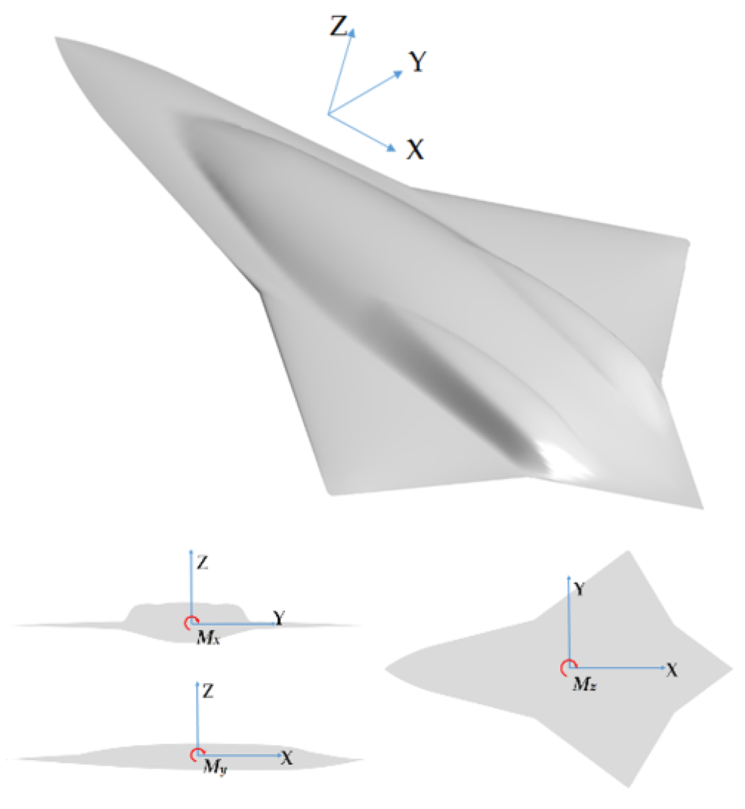
2.1. Research Model

Figure 1 shows the model used herein. The configuration comprises a diamond-shaped wing and lift-fuselage with a sharp leading-edge strake. The wing has a leading-edge back-swept angle of 52° and a trailing-edge forward-swept angle of 30°. On the upper surface, a modified top-mounted inlet, and two engine bumps are arranged. Some of the main parameters of the configuration are listed in Table 1.
According to references [5,6,7], an elevon and three different SSDs (SSD1, SSD2, and SSD3) are primarily designed. The positions of the control surfaces are shown in Figure 2, and some related parameters are displayed in Table 1, in which We and Ws are the widths of the elevon and SSDs, and Cx (Position Parameter) is the length from the wing tip to the outer end face of control surface, respectively. To reduce the influence of the control surface on the radar stealth performance of an aircraft, the trailing edges of SSDs are all parallel to the trailing edges of the main wings [3]. The area, length, and spanwise position of the three SSDs remained unchanged. The elevon is located behind the SSD. The leading edge of the elevon is parallel to the trailing edge of the wing, and the area is slightly smaller than the drag rudder. The baseline configuration is the one with no deflection on the control surface. In addition, it is assumed that the cavity caused by unfolding the SSD can be ignored because the SSD thickness is relatively small.
Several aerodynamic parameters are defined according to the reference [19]. Angle of attack (α) is defined as the angle between the main chord and the freestream velocity. Other concerned coefficients are defined as follows:
C L = L 1 2 ρ v 2 S r e f  
C D = D 1 2 ρ v 2 S r e f  
C l = M x 1 2 ρ v 2 S r e f b 2  
C m = M y 1 2 ρ v 2 S r e f c
C n = M z 1 2 ρ v 2 S r e f b 2
where CL, CD, Cl, Cm, and Cn denote the coefficients of lift, drag, rolling moment, pitching moment, and yawing moment, respectively. L and D are lift force and drag force, while Mx, My, and Mz are the rolling moment, pitching moment, and yawing moment, as shown in Figure 1. Furthermore, ρ and v are the density and velocity of the freestream, and c, b, and S r e f are mean aerodynamic chord, wingspan, and reference area of the aircraft, respectively. In this study, right-yawing, right-rolling, and nose-up moments were positive while left-yawing, left-rolling and nose-down moments were negative.

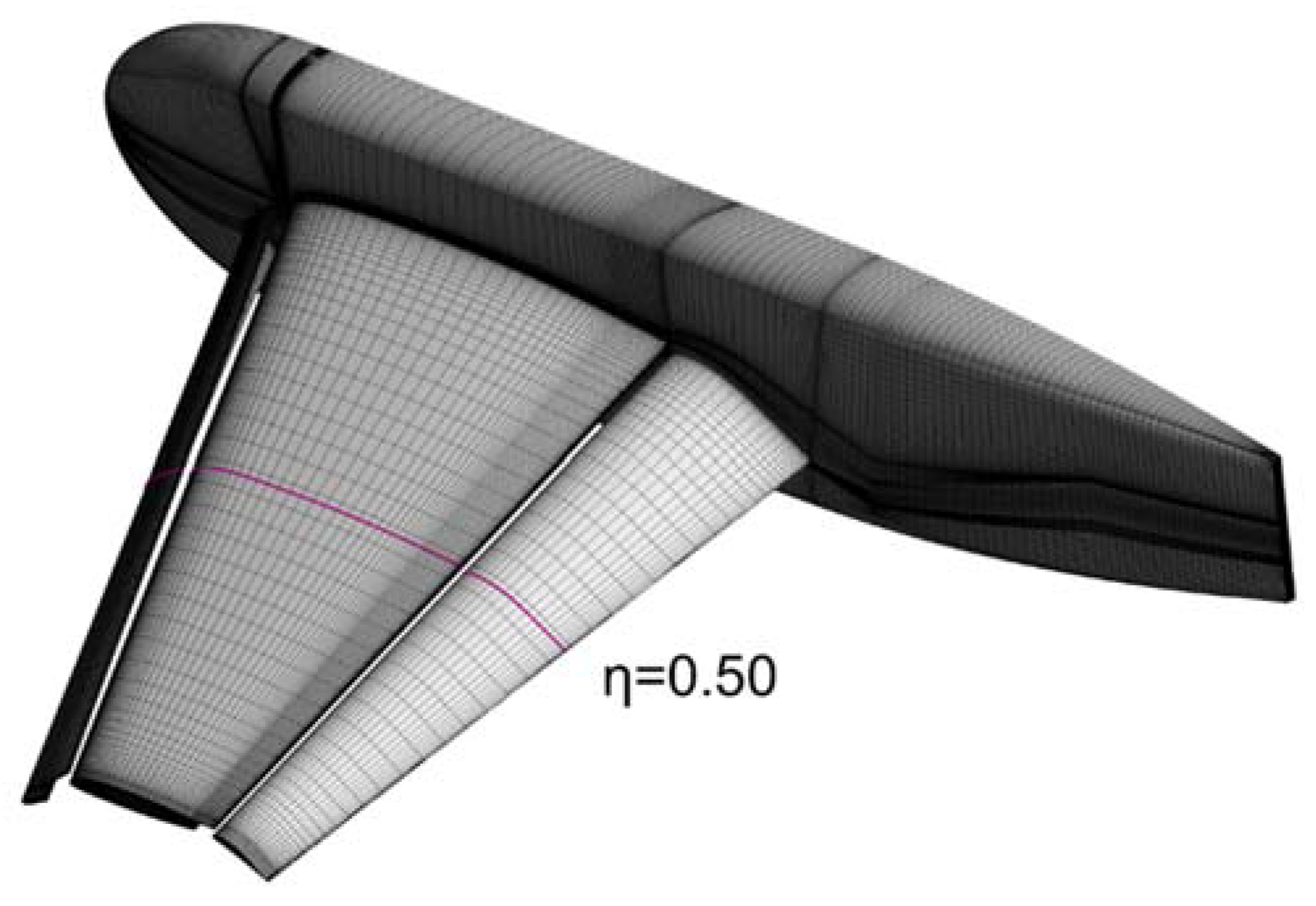
2.2. Numerical Method and Verification

The calculations in this study were conducted using the ANSYS CFX platform. The numerical method was based on the finite volume approach to solve the Reynolds Averaged Navier–Stokes (RANS) equations. The second-order central difference scheme was adopted to discretize the viscous term. Time discretization was accomplished using the second-order Euler scheme. The Shear Stress Transport (SST) model was selected as the turbulence model owing to its simulative capacity of flow separation, which is the common flow phenomenon of a configuration with a control surface [20]. Free-flow and no-slip boundary conditions were separately assigned to the far-field surfaces and all solid surfaces.
Configuration 8 of the NASA Trap-wing models was selected as the standard model for verification. The deflection angles of the leading-edge slat and trailing-edge flap were 30° and 20°, respectively. The calculation conditions were Ma = 0.2 and Re = 4.3 × 10⁶, which were the same as those of the wind tunnel [21]. The computational angles of attack (α) ranged from −4° to 28°, and the spacing was 4°.
A multi-block structured H–H-type grid with approximately 6,000,000 grid nodes was generated, with an O-type mesh around the model. The grid grew by 1.2 with a y+ of 1. The far field was twenty times the length of the mean aerodynamic chord. The surface grid of the model is showed in Figure 3 and η is the dimensionless spanwise position of the selected section.
Using the above numerical method and grid, calculation results (CFD) were obtained, while the experimental (EXP) results were obtained from reference [20]. Figure 4a,b show the comparison of the lift coefficient (CL) and drag coefficient (CD) between the numerical simulation and wind tunnel test of Configuration 8. The results show that the aerodynamic forces at small and medium angles of attack are in good agreement, while there are differences between the numerical simulation and wind tunnel test results at high angles of attack, which may be related to the vortex breakdown or possibly unsteady effects [22]. A comparison of the pressure coefficient (Cp) distributions of the typical section is shown in Figure 4c,d. Despite a slight difference, the Cp distributions of CFD and EXP were almost identical. Therefore, it can be confirmed that the numerical method applied herein can effectively predict the aerodynamic performance of a configuration with control surfaces.

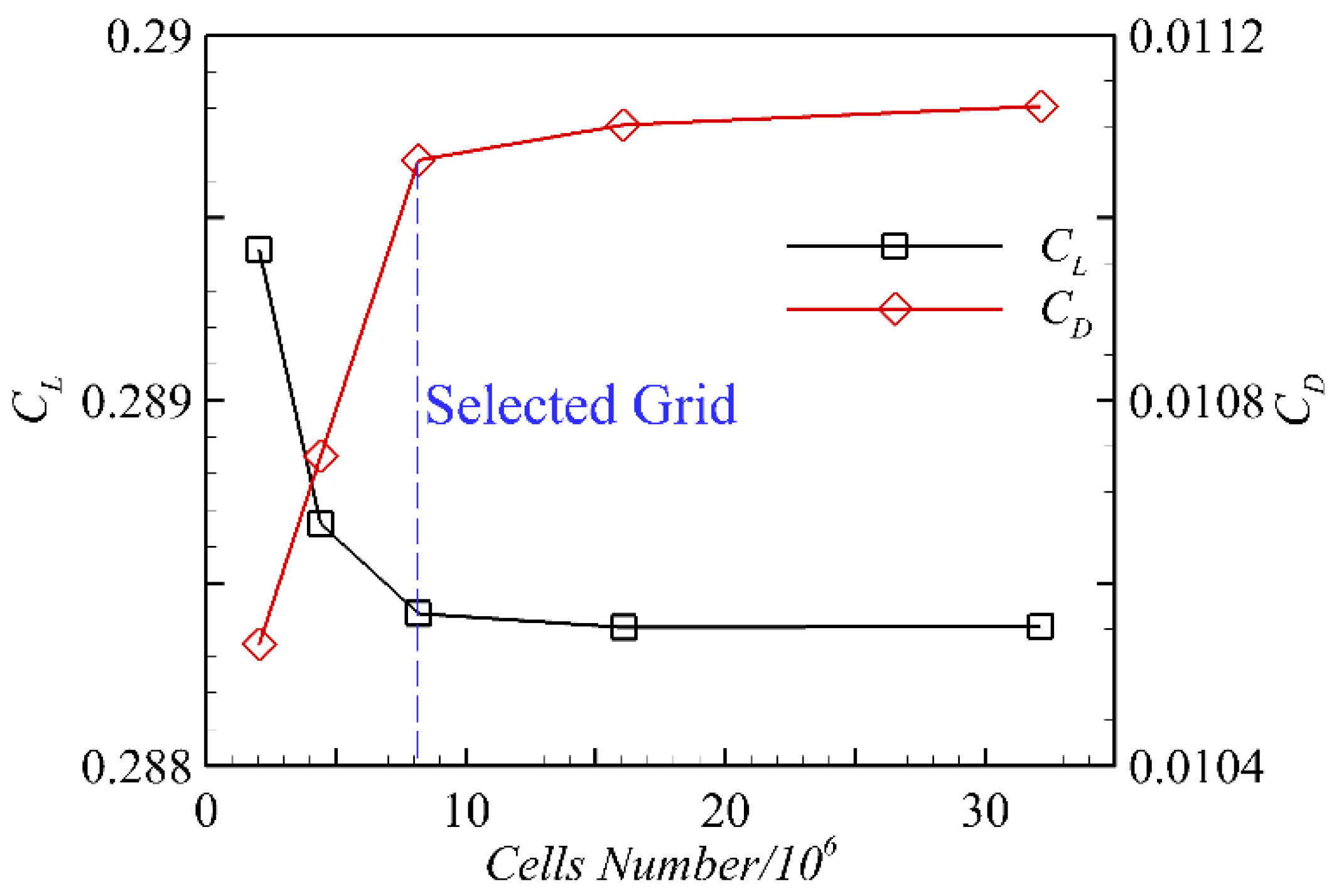
2.3. Grid Convergence Study

To conduct the numerical simulations, multi-block structured grids with H–H topology were generated for the right semi-span of the configurations using ANSYS ICEM CFD mode; the far field was twenty times the mean aerodynamic chord length. A grid convergence study was conducted using the configuration with the elevon and SSD deflected at Ma = 0.2 and α = 6°. Five different grids with 2,232,337 cells, 4,595,910 cells, 8,067,578 cells, 16,272,734 cells, and 32,344,411 cells, respectively, were employed with the same computing domain and grid topology. The result is displayed in Figure 5: CL and CD tended to converge with the cells number increasing, and the grid with about 8 million cells was selected for the computation. The grid had an O-type mesh around the model with a grid growth rate of 1.2 and a y+ of 1. As shown in Figure 6, grid refinement was employed in typical regions such as the leading edges, trailing edges, and control surfaces. In the calculation in this study, the configurations with different deflection angles of the control surface adopted the same grid topology and grid node distribution to reduce the influence of grid changes. The computational conditions were Ma = 0.2 and Re = 3.98 × 10⁷, which is a typical low-altitude maneuvering state for the studied aircraft herein according to the reference [23,24]. In addition, the grids of the baseline configuration and the configurations with different control surface deflections were patched in CFX to obtain the yawing, rolling, and pitching moments. By reflection option in CFX, the grid of baseline was placed on the left side, while the grid of the other configuration was on the right side. The Interface function of CFX-Pre was used, and the symmetry faces of the two grids could be set as Interface Side1 and Side2, correspondingly, for the node distributions of the symmetry faces were identical.

3. Control Characteristics of Single Rudder
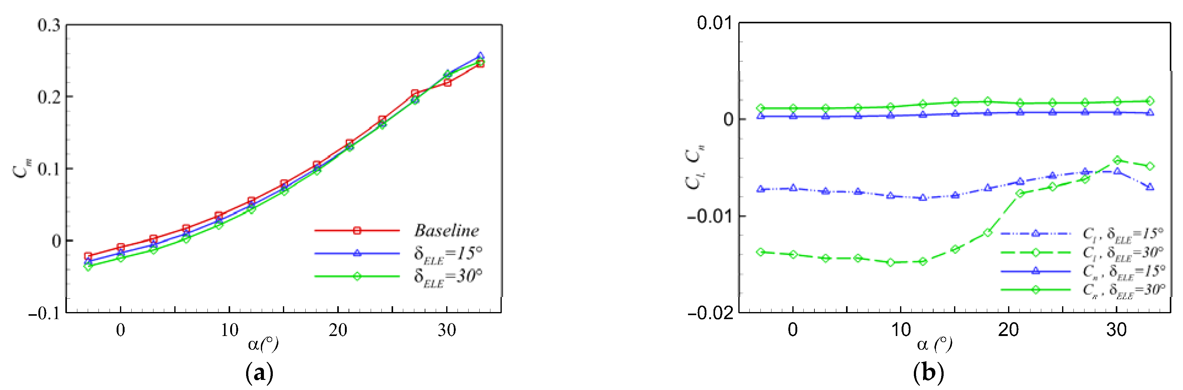
3.1. Elevon

The FCR studied herein still adopted the traditional elevon. Although the shape and deflection mode of the elevon did not change, the elevon deflected together with the SSD, generating the coupling flow that directly determines the aerodynamic performance of the FCR. Therefore, analyzing and mastering the aerodynamic characteristics of the elevon is necessary.
In this study, right-wing control surfaces of the configuration were selected as the research objects. When the right elevon deflects downward, the wing trailing-edge local curvature increases, and the lift and drag on the right side of the aircraft increase simultaneously. The difference between the drag and lift on both sides of the configuration will produce the yawing moment Cn and couple the rolling moment Cl, which will also lead to a change in the pitching moment Cm. To quantify the coupling effect of the control surface deflections, the longitudinal and lateral coupling effect factors γp and γr are defined as follows:
γ p = | C m C m 0 C n   |  
γ r = | C l C n   |  
where Cm0 is the pitching moment of the baseline configuration, and Cm, Cn, and Cl denote the pitching moment, yawing moment, and rolling moment of the configurations with the deflected control surfaces, respectively. The coupling effect factor can clearly obtain the relation between the yaw moment and the coupled rolling and pitching moments when the control surfaces deflect. The smaller the coupling effect factors, the weaker are the coupling effects, which are more conducive to decoupling.
Figure 7 shows the three-axis moments of the elevons with deflection angles of 15° and 30°. The yawing moments provided by the elevon change gently as the angle of attack increases, coupled with a large reverse rolling moment and nose-down moment, making the pitching moments smaller than those of the baseline configuration. The yawing moment and rolling moment generated by the elevon increased with an increase in the deflection angle; however, when the deflection angle was 30°, the rolling moment increased nonlinearly after an angle of attack of 12°, which was mainly caused by the failure of the elevon due to flow separation.
Table 2 lists the moments when the elevon is deflected downward at α = 6°. The yawing moment is 0.00032, the pitching moment variation is −0.00761, the coupled rolling moment is −0.00749, and the γp, γr are approximately 23.40 and 23.78, respectively. The results show that the yaw moment provided by deflecting the elevon is small, and it is strongly coupled with longitudinal and lateral control. Therefore, it is not suitable to use the elevon alone as a directional control surface.

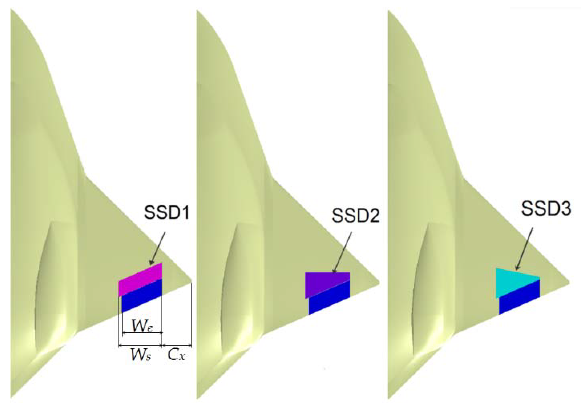
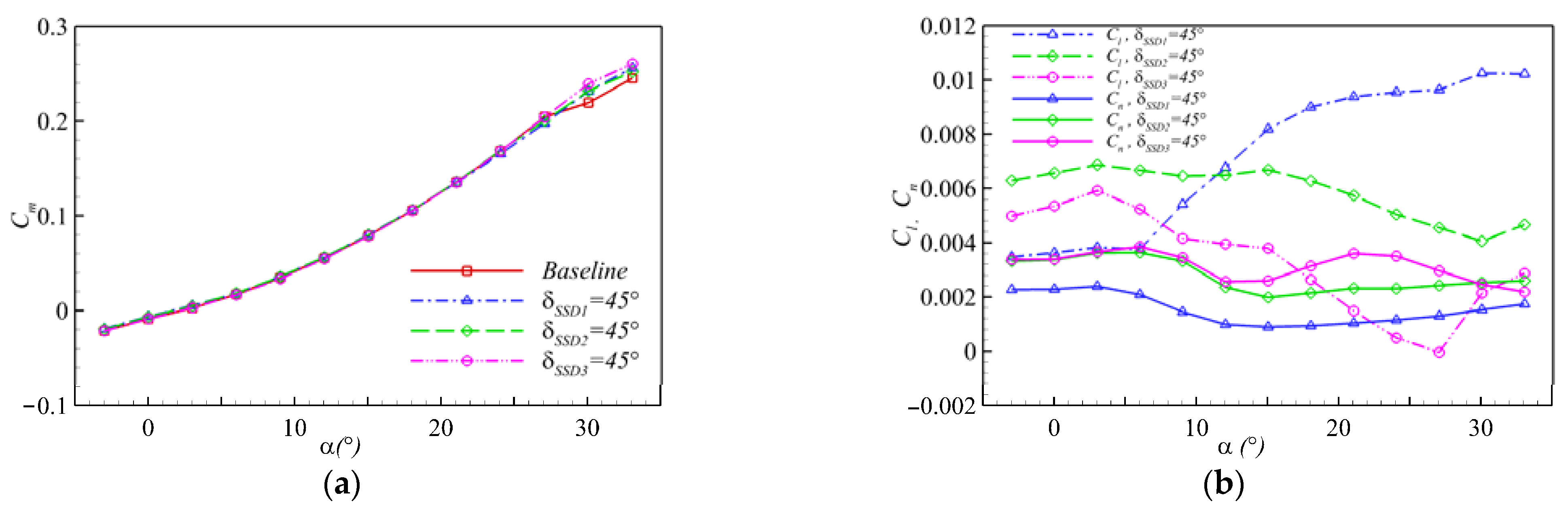
3.2. Spoiler Slot Deflector

Although SSD is a thin plate, the windward area is increased when the SSD on the upper surface of the right-wing is unfolding. As a result, the drag on the right side increased. The difference in drag on both sides of the aircraft produces a yawing moment. Meanwhile, when the SSD unfolds, the flow needs to bypass the SSD, resulting in flow separation behind it. Hence, the local speed and negative pressure were reduced, resulting in the loss of lift of the right-wing. Therefore, the yawing moment generated by unfolding the SSD is coupled with the rolling moment, accompanied by a change in the pitching moment.
Based on the control mechanism of the SSD, in this section, we study the influence of the leading-edge sweep angle of the SSD on the control characteristics. When the leading edge of the SSD sweeps backward, the sweep angle Λ > 0 and Λ < 0 when the leading-edge sweeps forward. For the configuration with the diamond-shaped wing studied herein, three SSDs with different leading-edge sweep angles were designed: SSD1 (Λ = −30°), SSD2 (Λ = 0°), and SSD3 (Λ = 15°).
The aerodynamic moment characteristics of the three SSDs are shown in Figure 8 when they unfold by 45°. The SSDs can produce right-yawing and right-rolling moments, and the change in pitch moment is not obvious. Table 3 shows the descriptions of control characteristics for the three SSDs at different α.
Figure 9 shows the spatial streamlines near the three SSDs when they unfold by 45° at α = 6°. The separation regions behind SSD2 and SSD3 are significantly larger than those behind SSD1, resulting in greater drag variation and, consequently, a greater yawing moment. Table 4 lists the moments when the SSDs unfold by 45° at α = 6°. Table 5 compares the aerodynamic moments characteristics of the elevon and SSDs at α = 6°. Although the coupling effect factors are much smaller than those of the elevon, the values are still considerable, indicating that there exists an issue of aerodynamic moment coupling for the configurations.
From the above analysis, it can be inferred that for a tailless configuration with a diamond-shaped wing, the yawing moment provided by the SSD with the leading edge parallel to the trailing edge of the main wing is limited, and the coupled rolling moment will increase nonlinearly. At high angles of attack, the rolling moment is much greater than the yawing moment, which is unfavorable for flight stability. The SSDs with leading-edge sweptback angles of 0° and 15° can provide a stronger yawing moment, and the rolling moments are smaller at high angles of attack. SSDs have more effective directional control than elevons, but they are coupled with lateral control. Consequently, utilizing the SSD alone could not offer satisfactory control characteristics, and a decoupling design is needed in subsequent studies.

4. Investigation on Flow Coupling Rudder

The tailless configurations cancel the vertical tail, which can generate lateral force to control the direction, and use deflecting one-side control surfaces to increase the one-side drag to produce the yawing moment. The analysis of the above section leads to an inference that when the SSDs and elevon are adopted for yawing control alone, they will produce simultaneous coupling of the yaw moment and greater rolling moment, thereby causing a change in the pitching moment. The coupling effect will have an adverse impact on attitude control; therefore, carrying out a decoupling design is necessary. The results show that when the right-side elevon deflects downward, the lift and drag increase simultaneously, resulting in a right-yawing moment and a coupled reverse rolling moment; when the right-side SSD is unfolding, the drag increases while the lift decreases, resulting in a right-yawing moment coupled with a right-rolling moment. Therefore, a flow coupling rudder composed of an SSD and its rear elevon is proposed for directional control. By adjusting the matching parameters of the elevon and SSD, the flow coupling between the SSD and elevon can produce the ideal effect of increasing drag and constant lift, which could improve the yawing moment and suppress or even eliminate the coupled rolling and pitching moment.

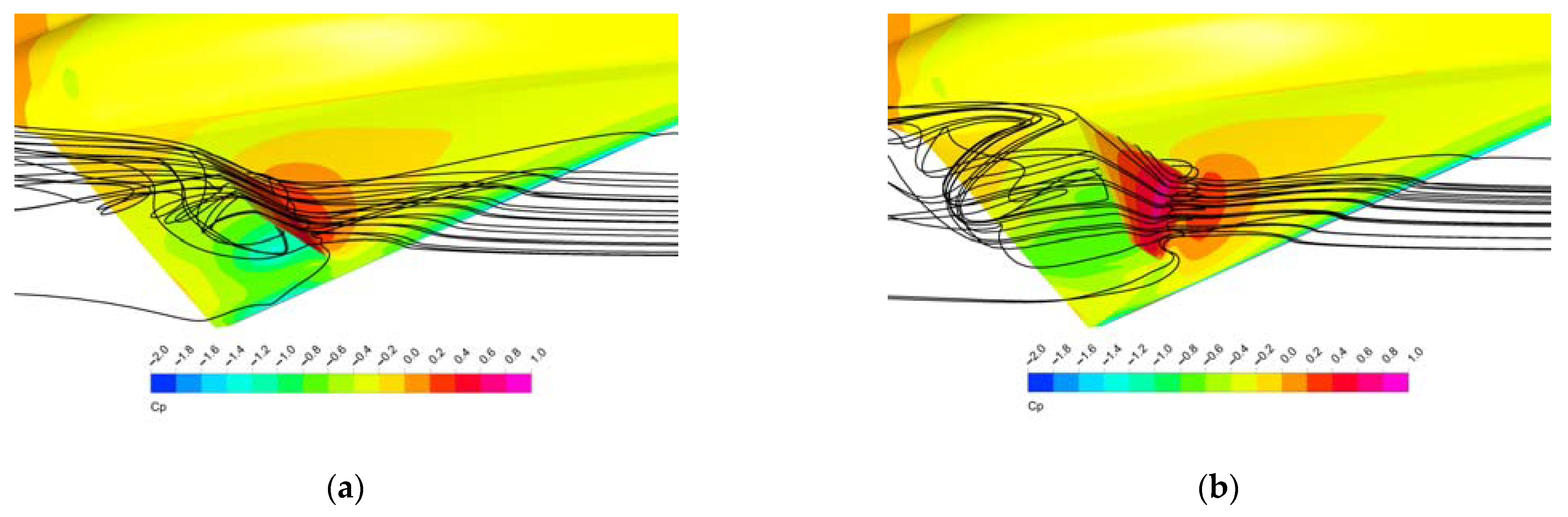
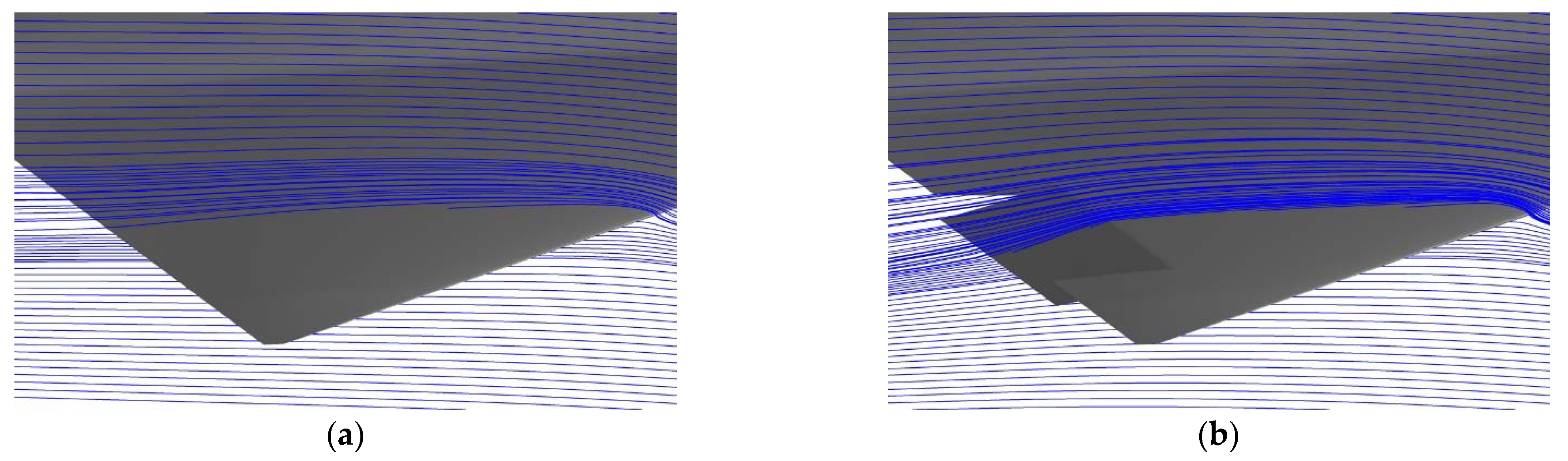
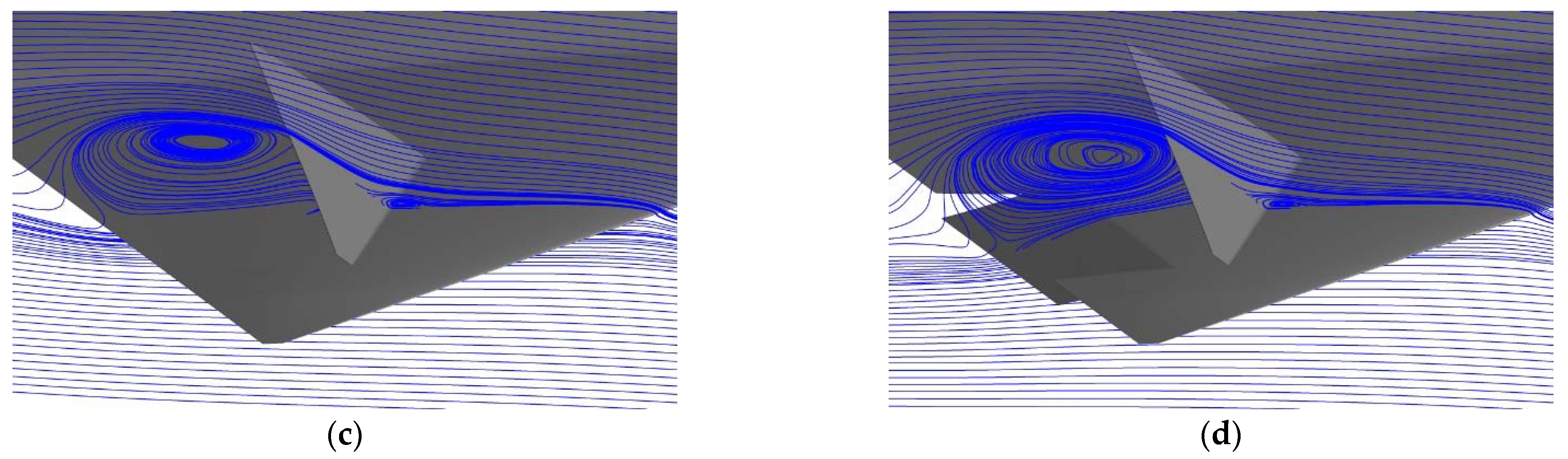
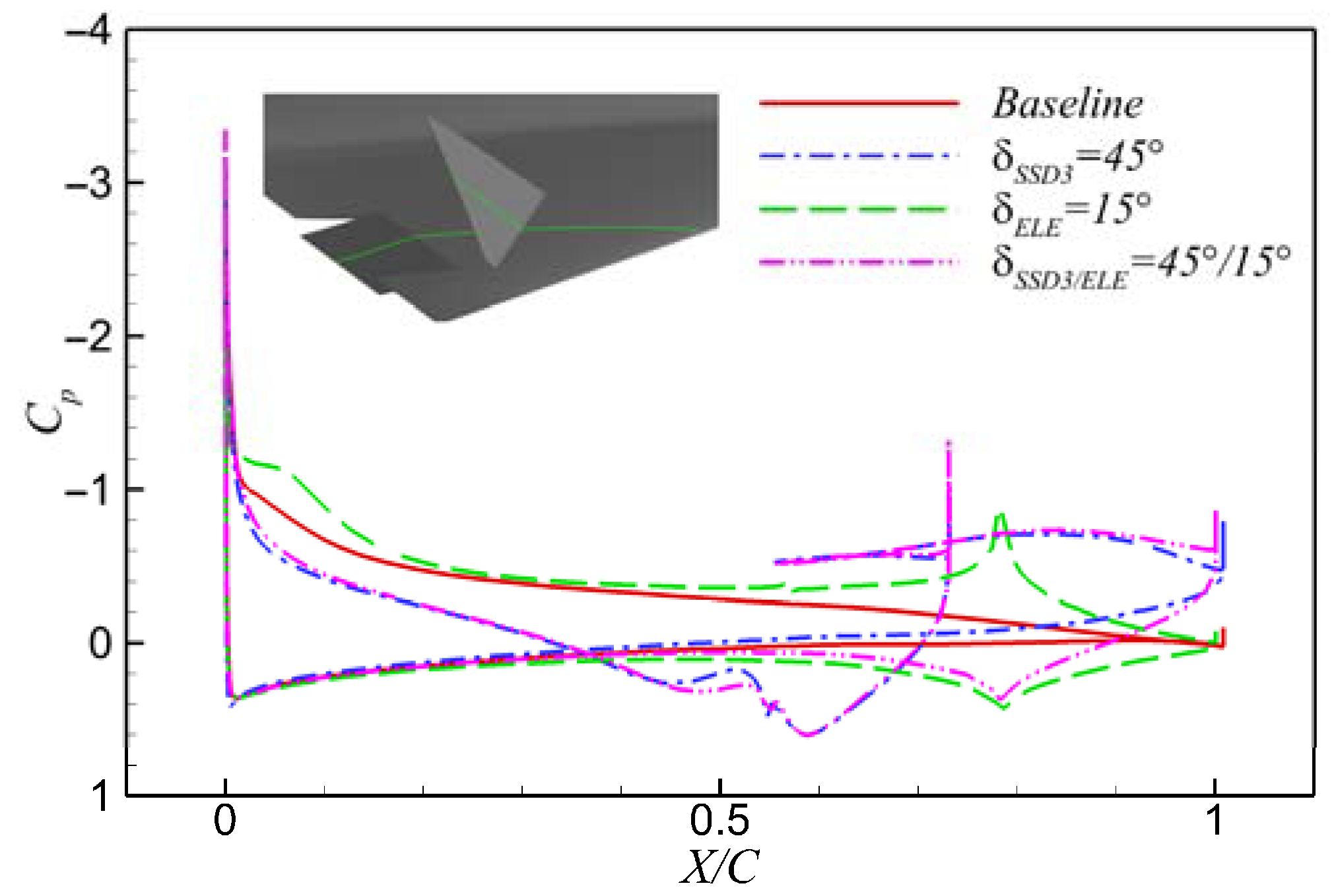
4.1. Flow Coupling Mechanism of FCR

To verify the effectiveness of the concept of FCR, elevon and three different SSDs compose three different FCRs. Figure 10 compares the lateral and directional control characteristics of the FCRs, corresponding SSDs, and elevons. From the comparison results, after the coupling design of the control surfaces, the yawing moments increase and the rolling moments decrease.
Figure 11 shows the three-axis moment characteristics of the three FCRs. In addition, Figure 11a and Table 6 show that the coupling design of FCR reduces the nose-down moments caused by the downward deflection of the elevon simultaneously. Table 7 shows the descriptions of control characteristics for the three FCRs at different α.
The application of control surfaces changes the flow around the wing, leading to a change in the lift and drag of the entire configuration. As a result, yawing, rolling moments, and changes in the pitching moment were generated. Figure 12 shows the section streamlines of the configurations, and Figure 13 shows the Cp distribution of the sections. Figure 14 shows the spatial streamlines colored by Cp around SSD3 and the corresponding FCR. The downward deviation of the right elevon by 15° increases the local camber of the airfoil. From the perspective of pressure distribution, the value of negative pressure on the upper surface increases, as well as that of the positive pressure on the lower surface; thus, the lift of the right-wing increases. The elevon is located behind the center of gravity; thus, an increase in lift will produce a nose-down moment. The deflection of the right elevon leads to an increase in induced-drag, friction-drag, and form-drag; thus, the drag of the right-wing increases. Consequently, the asymmetries of lift and drag on both sides of the configuration will produce the corresponding rolling and yawing moments.
When the SSD unfolds upward by 45° alone, the windward area increases. The SSD resists the flow near the fore of the wing on the upper surface, the flow velocity decreases, the pressure increases, and the negative pressure value decreases. The closer it is to the SSD, the larger is the variation of the negative pressure on the upper surface, forming a large differential pressure drag, and the airflow fills from the edge of the SSD to its leeward area to form a separation vortex. Owing to the influence of the separation vortex, the airflow on the lower surface of the wing washes up and accelerates, reducing the pressure on the entire lower wing surface. The closer it is to the trailing edge, the more is the pressure reduction, and these flow phenomena show that when the SSD unfolds, the pressure distribution changes complexly, resulting in a change in drag and lift; hence, the change in pitching moment and rolling moment is accompanied by a change in the yawing moment.
However, when adopting the FCR, the flow characteristics are the coupling of the flow characteristics when the SSD and the elevon are adopted separately, the SSD interference is dominant on the upper surface of the wing, and the pressure distribution shape is similar to that when the SSD is adopted alone, the lower surface of the wing is dominated by the deflection of the elevon, and the pressure distribution is similar to that when the elevon is deflected alone. However, owing to the upwash effect of the separation vortex when the SSD unfolds, the pressure on the lower surface of the wing with FCR is smaller than that when the elevon is deflected alone. Table 8 lists the aerodynamic coefficients variation for the configurations at α = 6°. The elevon and SSD can both provide a drag increasing effect and enhance the directional control ability. In addition, the lift increment caused by the elevon can offset, weakening the lift change caused by the deflection of the SSD, thus diminishing the coupled rolling moment and pitching moment.
In summary, the FCR design concept for a low-aspect tailless configuration with a diamond-shaped wing can improve the yaw moment and reduce the coupled rolling moment and pitching moment. However, the matching parameters of SSD and elevon need to be further studied. In addition, the FCR composed of SSD3 with a sweptback leading edge and elevon can provide an efficient yawing moment at small and medium angles of attack and weaken the coupled rolling and pitching moments.

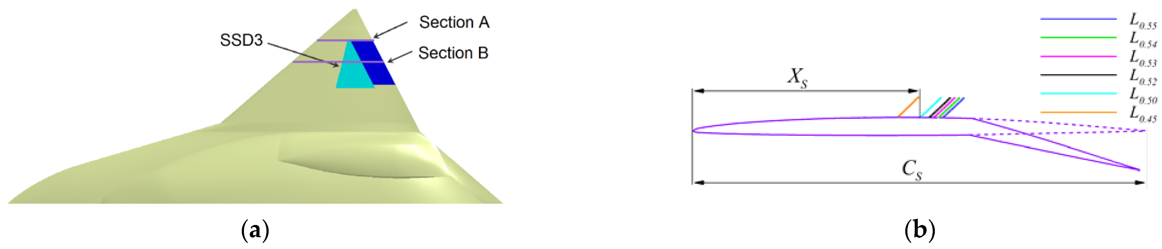
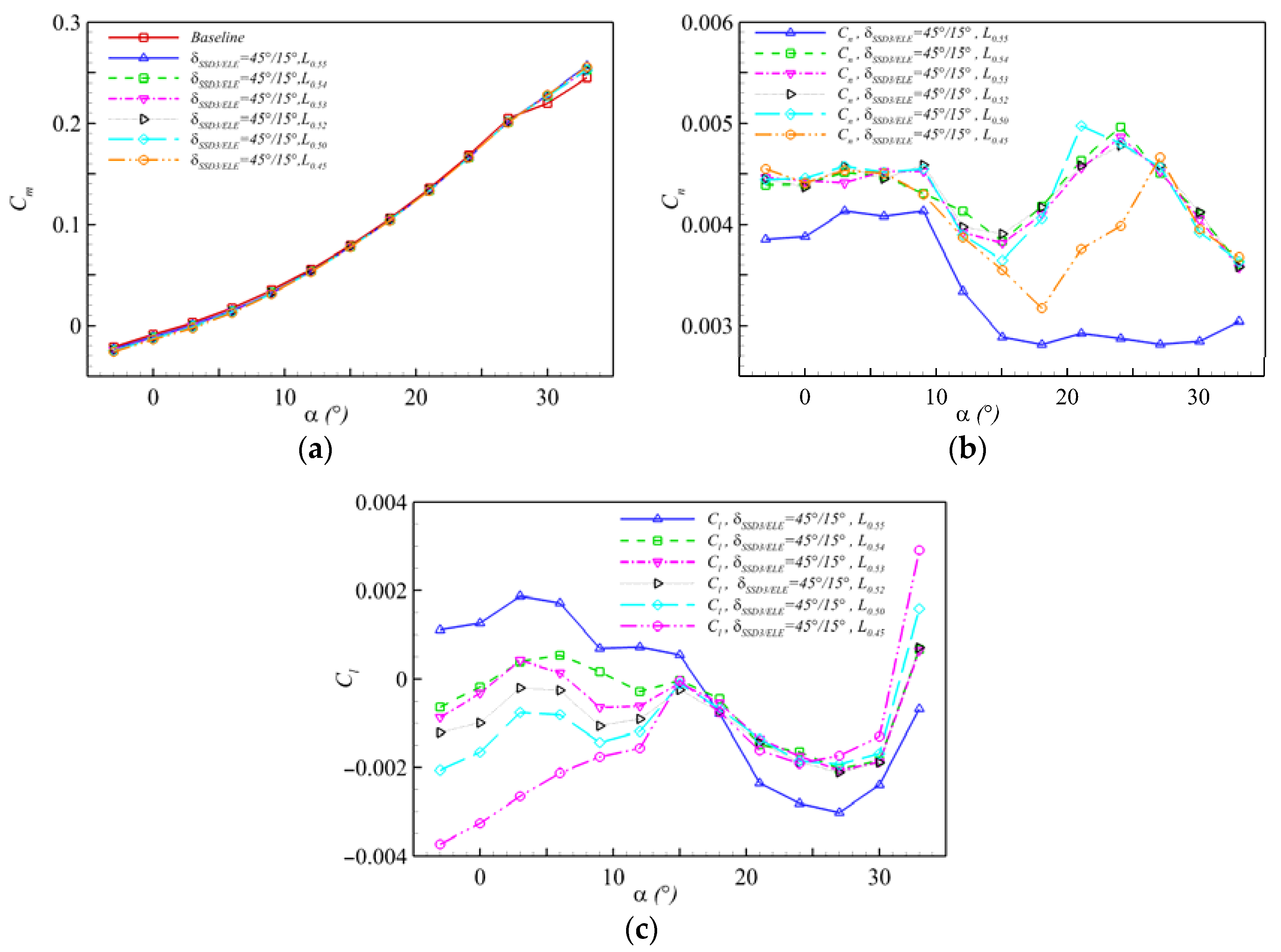
4.2. Location Effect of SSD3 of FCR

Combined with the analysis in the previous section, the FCR composited of SSD3 and the elevon was selected for further study owing to its good control characteristics at small and medium angles of attack. Definition parameter Ln: The dimensionless chord position of the outer end face of the SSD is n. Ln is defined as Equation (8):
L n = X S C S  
where Xs is the length from the leading edge to SSD, while Cs is the chord length of the section, as shown in Figure 15b. The positions of the SSDs are shown in Figure 15. The original parameter is L0.55.
After the SSD moves forward, the yawing moment increases considerably because the separation area generated by the air flow bypassing the SSD is larger, and a greater drag is generated, thereby increasing the yaw moment, as shown in Figure 16. The rolling moment decreases and even reverses at small angles of attack. This is because the lift reduction caused by the forward placement of the right SSD in chordwise direction is gradually greater than the lift increment caused by the downward deflection of the elevon. According to the results, the rolling moment generated by the FCR with the SSD3 location of L0.54 is a small right-rolling at small and medium angles of attack, and it can provide an effective yawing moment; thus, the location is selected for further study.

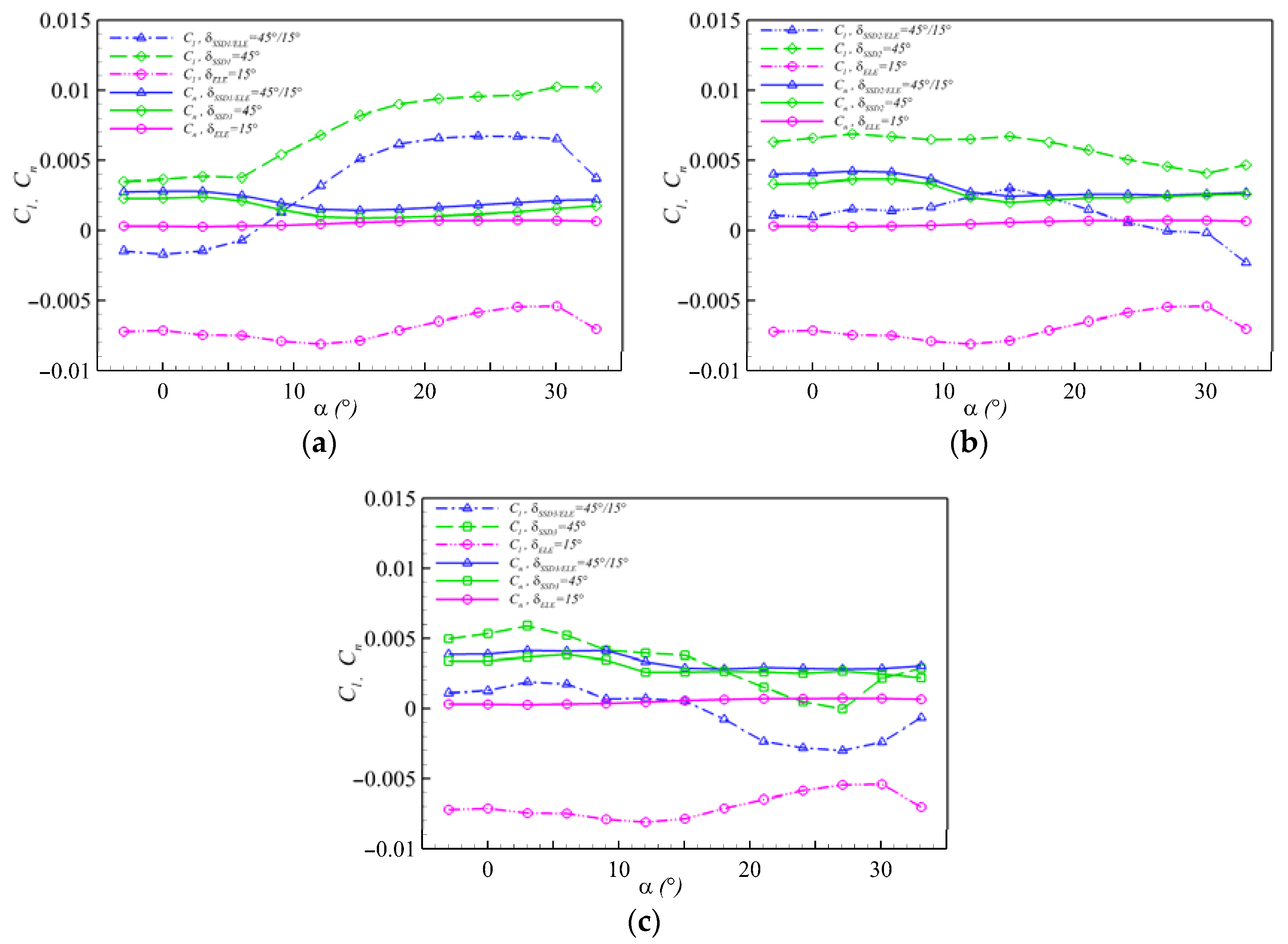
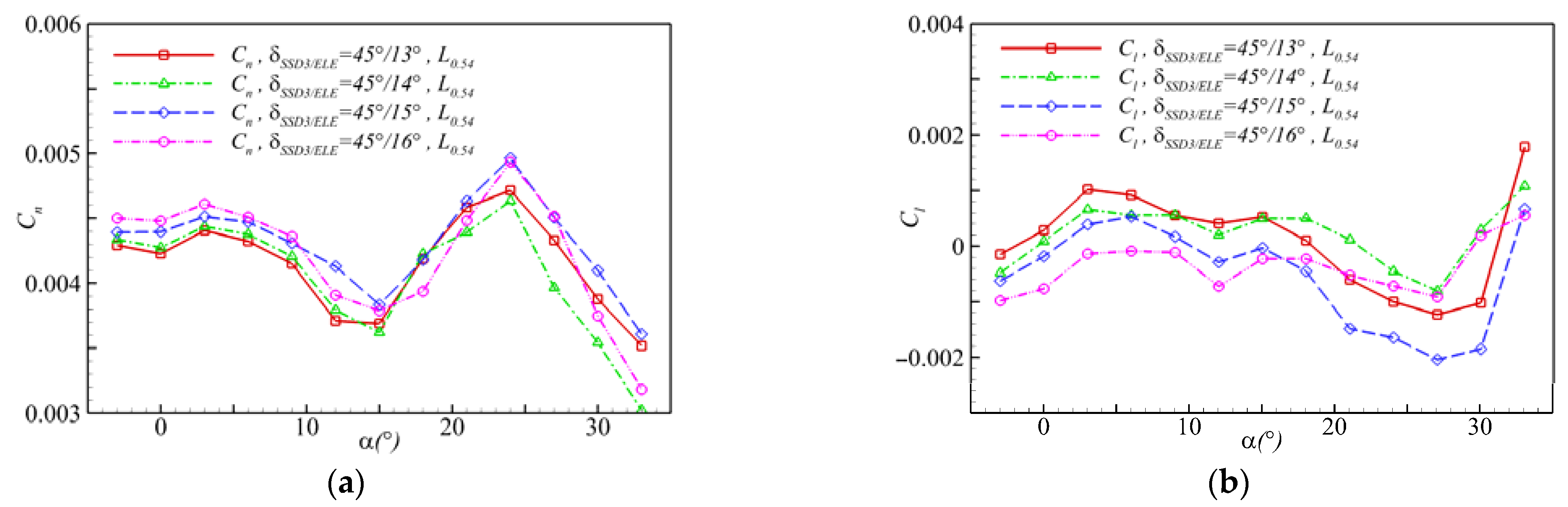
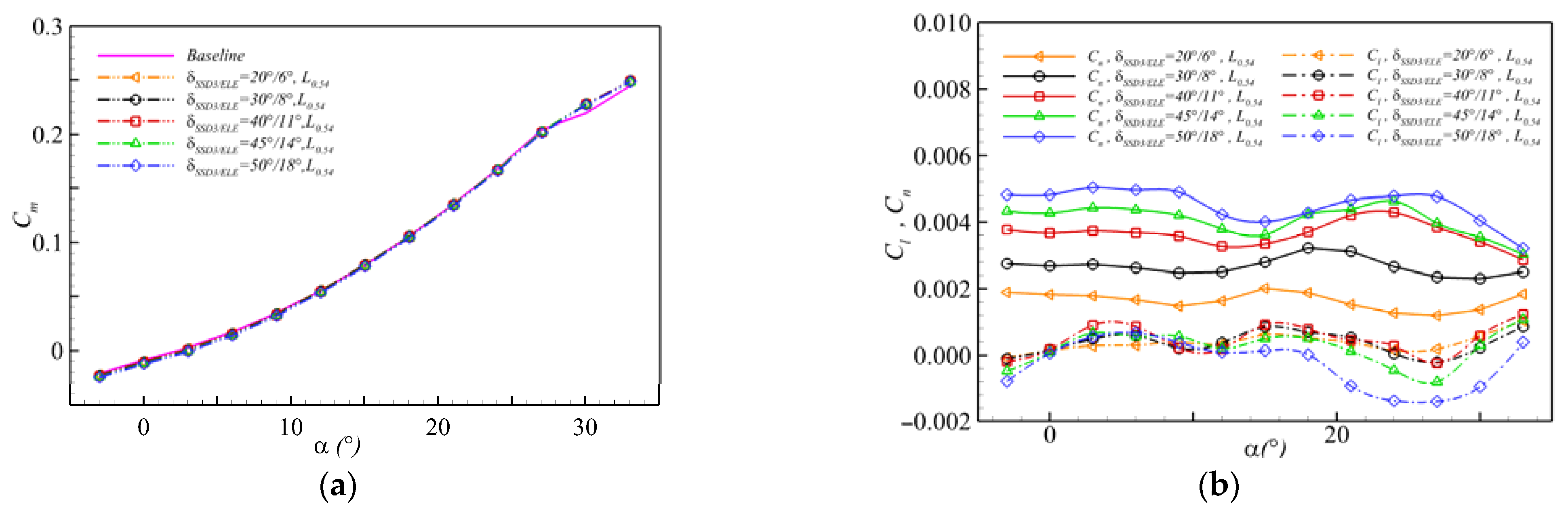
4.3. Effect of Collocating Deflection Angles of the FCR

After determining the appropriate position of SSD3, SSD3 unfolding was maintained at 45°, and the deflection angle of the corresponding elevon was adjusted to determine the better collocating deflection angles of the FCR. Analysis of the comparison results of yawing and rolling moments: it can be inferred from Figure 17a,b that the FCR with δSSD3/ELE = 45°/14° can provide an obvious right-yawing moment, and the coupled rolling moments change gently at small and medium angles of attack, and the quantity value is small and positive. Figure 18 shows the variation trend of the directional and lateral control characteristics of the FCR with the increase in the deflection angle of the elevon at different angles of attack. There is a corresponding collocating deflection angle of the FCR under different flight attitudes that provides the yawing moment when the rolling moment is eliminated. This indicates that pure directional control can be achieved.
Figure 19 shows the three-axis moment characteristics of the five groups of FCRs. The yaw moments provided by the FCRs composed of five types of collocating deflection angles are considerably greater than the rolling moments at small and medium angles of attack, while the difference in the pitching moment between the configuration with the five different FCRs and the baseline configuration is small.
The results of this section show that the FCR proposed herein can satisfy the requirements of directional stability and control of lateral maneuvering flight for a low-aspect tailless configuration with a diamond-shaped wing, and there is basically no need to compensate for the pitching and rolling moments, and under different angles of attack, pure heading control can be realized by reasonably adjusting the collocating deflection angles of FCR.

4.4. Selection Principle of Key Parameters of FCR

Based on the analysis in the above sections, it can be concluded that the selection principles of the FCR parameters for a low-aspect tailless configuration with the diamond-shaped wing are as follows: utilizing SSD with a sweptback leading edge in the FCR can significantly improve the directional control and flight stability ability, and the leading-edge sweep angle needs to be determined according to the geometric parameters of the configuration, the position of the SSD should be moved forward appropriately, and the location should be determined by numerical analysis; for the configuration studied in this paper, in the range of 20° ≤ δSSD ≤ 50° and 5° ≤ δELE ≤ 20°, reasonably adjust collocating deflection angles of FCR, the directional stability of the maneuvering flight state can be appreciable and the coupled rolling and pitching moments can be small at α ≤ 18°, the max yawing moment obtained can approach to about 0.005 while the coupling effect factors γp and γr are only about 0.38 and 0.11, respectively; the rolling moment can be eliminated and the pure heading control can be realized by reasonably selecting the angles.

5. Conclusions

Aiming at the directional control problem of a low-aspect tailless configuration with a diamond-shaped wing, we herein selected the SSD and elevon as the basic control surfaces and carried out the study. The conclusions are as follows:
  • When adopting the elevon or SSD alone, it not only provides yawing but also couples the rolling and pitching moments. It requires the cooperation of other control surfaces to reduce or even eliminate coupled moments;
  • For the configuration with a diamond-shaped wing, the SSD with an appropriate sweptback leading edge is more conducive to improving the directional control and providing more stable control than the SSD with the leading edge parallel to the trailing edge of the wing;
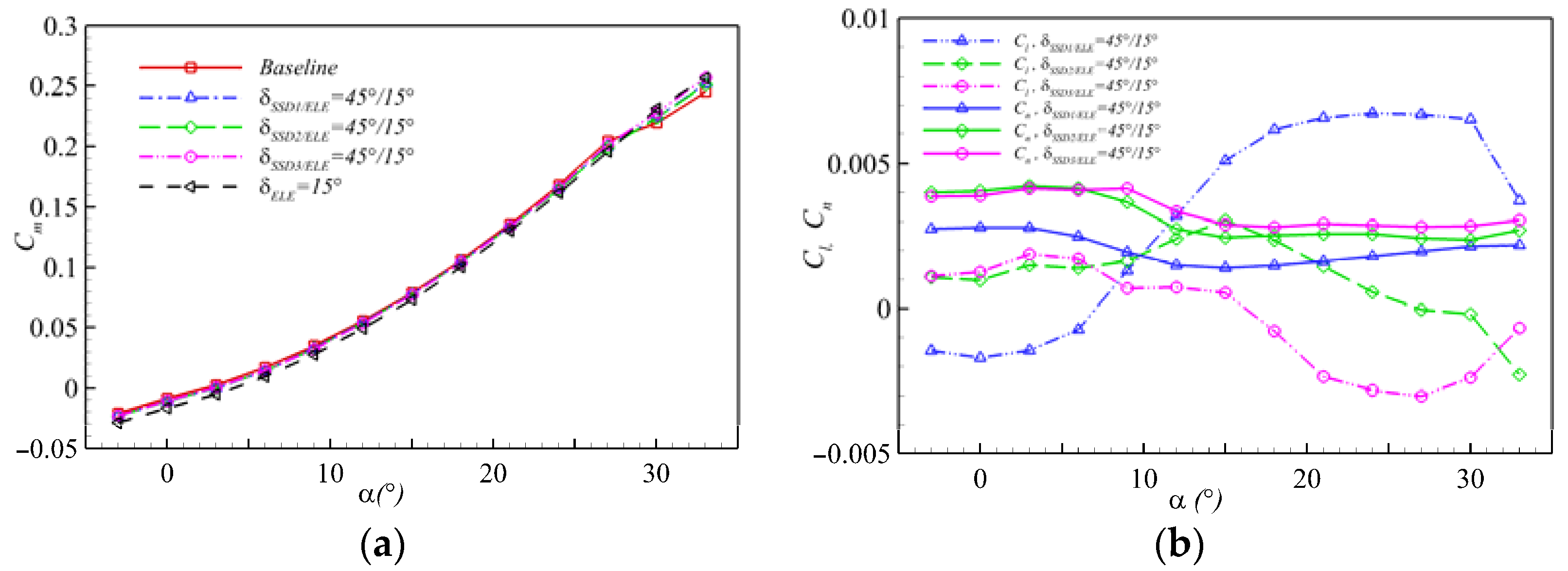
  • In terms of the configuration studied herein, adjust collocating deflection angles of FCR reasonably, the directional stability of maneuvering flight state can be increased and the coupled rolling and pitching moments can be weakened or even be eliminated at small and medium angles of attack;
  • The concept of FCR for the tailless configuration could provide a satisfactory yaw moment and weaken or even eliminate the coupling pitching and rolling moments. The FCR can improve the directional control and aerodynamic moment coupling issues by only one group of control surfaces, providing more options for the other side of the control surface to participate in other controls.
The investigation presented herein can provide a method for directional control for a similar configuration. However, our study mainly focused on the low-speed directional control of a low-aspect tailless configuration with a diamond-shaped wing, and future work will be conducted on the control issue in other states such as the transonic or supersonic states. In addition, new technology based on active flow control has developed rapidly with respect to the control of aircraft, which will also be studied in the future.

Author Contributions

Conceptualization, B.Z. and Z.L.; methodology, Z.L.; software, Z.L.; validation, Z.L.; formal analysis, B.Z. and Z.L.; investigation, Z.L.; resources, Z.L.; data curation, B.Z. and Z.L.; writing—original draft preparation, Z.L.; writing—review and editing, B.Z. and Z.L.; visualization, B.Z. and Z.L.; supervision, B.Z.; project administration, B.Z.; funding acquisition, B.Z. All authors have read and agreed to the published version of the manuscript.

Funding

This research was supported by the Fundamental Research Funds for the Central Universities (Nos. 3102019JC009).

Institutional Review Board Statement

Not applicable.

Informed Consent Statement

Not applicable.

Data Availability Statement

The data presented in this study are available on request from the corresponding author.

Acknowledgments

The authors would like to deliver their sincere thanks to the editors and anonymous reviewers.

Conflicts of Interest

The authors declare no conflict of interest.

References

  1. Küchemann, D. The Aerodynamic Design of Aircraft; AIAA: Reston, VA, USA, 2012; pp. 338–438. [Google Scholar]
  2. Raymer, D.P. Aircraft Design: A Conceptual Approach; AIAA: Washington, DC, USA, 1989; pp. 33–47. [Google Scholar]
  3. Sang, J.H. Low-Observable Technologies of Aircraft; Aviation Industry Press: Beijing, China, 2013; pp. 57–68. [Google Scholar]
  4. Fang, B.R. Aircraft Aerodynamic Configuration Design; Aviation Industry Press: Beijing, China, 1997; pp. 97–130. [Google Scholar]
  5. Bowlus, J.A.; Multhopp, D.; Banda, S.S. Challenges and opportunities in tailless aircraft stability and control. In Proceedings of the AIAA Guidance, Navigation and Control Conference, New Orleans, LA, USA, 11–13 August 1997. [Google Scholar] [CrossRef]
  6. Dorsett, K.M.; Mehl, D.R. Innovative Control Effectors (ICE); WPAFB: New Haven, CT, USA, 1996. [Google Scholar]
  7. Gillard, W.J. Innovative Control Effectors (Configuration 101) Dynamic Wind Tunnel Test Report; Air Force Research Laboratory, Wright-Patterson AFB: Dayton, OH, USA, 1998. [Google Scholar]
  8. Gillard, W.J.; Dorsett, K.M. Directional control for tailless aircraft using all moving wing tips. In Proceedings of the 22nd Atmospheric Flight Mechanics Conference, New Orleans, LA, USA, 11–13 August 1997. [Google Scholar] [CrossRef]
  9. Zuo, L.X.; Wang, J.J. Experimental study of the effect of AMT on aerodynamic performance of tailless flying wing aircraft. Acta Aerodyn. Sin. 2010, 28, 132–137. [Google Scholar]
  10. Ward, D.T.; Stout, L.J. Use of differential leading edge flaps for lateral control at high angle of attack. In Proceedings of the 24th Aerospace Sciences Meeting, Reno, NV, USA, 6–9 January 1986. [Google Scholar] [CrossRef]
  11. Li, Z.J.; Ma, D.L. Control Characteristics Analysis of Split-drag-rudder. Appl. Mech. Mater. 2014, 472, 185–190. [Google Scholar] [CrossRef]
  12. Smith, C.W.; Ralston, J.N.; Mann, H.W. Aerodynamic of Forebody and Nose Strakes Based on F-16 Wind Tunnel Test Experience; Langley Research Center: Fort Worth, TX, USA, 1979.
  13. Iwanski, K.P.; O’Rourke, M.J. F-15 forebody vortex flow control using jet nozzle blowing. J. Aircr. 1996, 33, 491–498. [Google Scholar] [CrossRef]
  14. Hunter, C.A.; Viken, S.A.; Wood, R.M.; Bauer, S.X.S. Advanced aerodynamic design of passive porosity control effectors. In Proceedings of the 39th Aerospace Sciences Meeting and Exhibit, Reno, NV, USA, 8–11 January 2001. [Google Scholar] [CrossRef] [Green Version]
  15. Stenfelt, G.; Ringertz, U. Lateral Stability and Control of a Tailless Aircraft Configuration. J. Aircr. 2009, 46, 2161–2163. [Google Scholar] [CrossRef]
  16. Zhou, Z.; Yu, Y.G.; Liu, G.; Chen, Z.B.; Heng, K.F. Comprehensive Study on yaw control characteristic of combined control surfaces of Flying wing configuration. Acta Aeronaut. Astronaut. Sin. 2020, 41, 523422. [Google Scholar] [CrossRef]
  17. Li, L.L.; Zhang, B.Q.; Li, P.F.; Zhang, M.H. Research on control technology of combined control surface for large tailless civil aircraft. Flight Dyn. 2013, 31, 450–454. [Google Scholar] [CrossRef]
  18. Zhang, B.Q.; Ma, Y.; Chu, H.B.; Chen, Z.L.; Chen, Y.C. Investigation on combined control surface for yaw control of low aspect ratio flying wing configuration. Acta Aeronaut. Astronaut. Sin. 2013, 34, 2435–2442. [Google Scholar] [CrossRef]
  19. Anderson, J.D. Fundamentals of Aerodynamics; McGraw-Hill Education: New York, NY, USA, 2005; pp. 19–26. [Google Scholar]
  20. ANSYS. ANSYS User Manual CFX-Solver Theory Guide; ANSYS Release 18.0; ANSYS, Inc.: Canonsburg, PA, USA, 2017. [Google Scholar]
  21. Rumsey, C.L.; Slotnick, J.P.; Long, M.; Stuever, R.A.; Wayman, T.R. Summary of the first AIAA CFD high lift prediction work shop. J. Aircr. 2011, 48, 2068–2079. [Google Scholar] [CrossRef]
  22. Rumsey, C.L.; Gatski, T.B.; Ying, S.X.; Bertelrud, A. Prediction of high-lift flows using turbulent closure models. AIAA J. 1998, 36, 765–774. [Google Scholar] [CrossRef] [Green Version]
  23. Sha, Z.P. Aircraft Design Manual Volume 4: Conceptual Design of Military Aircraft; Aviation Industry Press: Beijing, China, 2005; pp. 15–31. [Google Scholar]
  24. Eduardo, S.; Howard, S. Conceptual design of a fifth generation unmanned strike fighter. In Proceedings of the AIAA Scitech 2019 Forum, San Diego, CA, USA, 7–11 January 2019. [Google Scholar] [CrossRef] [Green Version]
Figure 1. The coordinate system and sign convention for the research model.
Aerospace 09 00079 g001
Figure 2. Positions of different control surfaces.
Aerospace 09 00079 g002
Figure 3. Surface grid of NASA Trap-wing Configuration 8.
Aerospace 09 00079 g003
Figure 4. Comparison results of the experiment and CFD calculation of NASA Trap-wing Configuration 8 for Ma = 0.2, Re = 4.3 × 10⁶: (a) Lift curve; (b) Drag curve; (c) Cp comparison, α = 8°; (d) Cp comparison, α = 16°.
Aerospace 09 00079 g004
Figure 5. Grid convergence study at Ma = 0.2, α = 6°.
Aerospace 09 00079 g005
Figure 6. Computation grid for the studied model: (a) Surface mesh; (b) Mesh around the control surfaces.
Aerospace 09 00079 g006
Figure 7. Control characteristics when the elevon deflects alone for Ma = 0.2, Re = 3.98 × 10⁷: (a) Pitching moment; (b) Rolling and yawing moments.
Aerospace 09 00079 g007
Figure 8. Control characteristics when the three SSDs unfold by 45° alone for Ma = 0.2, Re = 3.98 × 10⁷: (a) Pitching moment; (b) Rolling and yawing moments.
Aerospace 09 00079 g008
Figure 9. Spatial streamlines near the control surface and Cp distributions around SSDs, Ma = 0.2, Re = 3.98 × 10⁷, α = 6°: (a) SSD1; (b) SSD2; (c) SSD3.
Aerospace 09 00079 g009aAerospace 09 00079 g009b
Figure 10. Yawing and rolling moments comparison of the elevon, SSDs, and corresponding FCRs, Ma = 0.2, Re = 3.98 × 10⁷: (a) The elevon, SSD1 and the corresponding FCR; (b) The elevon, SSD2 and the corresponding FCR; (c) The elevon, SSD3 and the corresponding FCR.
Aerospace 09 00079 g010
Figure 11. Control characteristics of the different FCRs for Ma = 0.2, Re = 3.98 × 10⁷: (a) Pitching moment; (b) Rolling and yawing moments.
Aerospace 09 00079 g011
Figure 12. Section streamlines for four configurations, Ma = 0.2, Re = 3.98 × 10⁷, α = 6°: (a) Baseline; (b) Elevon; (c) SSD3; (d) FCR.
Aerospace 09 00079 g012aAerospace 09 00079 g012b
Figure 13. Cp distribution for the sections of four configurations, Ma = 0.2, Re = 3.98 × 10⁷, α = 6°.
Aerospace 09 00079 g013
Figure 14. Spatial streamlines around the SSD3 and the corresponding FCR, Ma = 0.2, Re = 3.98 × 10⁷, α = 6°: (a) SSD3; (b) The corresponding FCR.
Aerospace 09 00079 g014
Figure 15. Position of SSD3: (a) Section location; (b) Locations of the outer end faces of SSD3 on Section A.
Aerospace 09 00079 g015
Figure 16. Control characteristics of the FCRs with different position of SSD3. Ma = 0.2, Re = 3.98 × 10⁷: (a) Pitching moment; (b) Yawing moment; (c) Rolling moment.
Aerospace 09 00079 g016
Figure 17. Control characteristics of the FCRs with different collocating deflection angles, Ma = 0.2, Re = 3.98 × 10⁷: (a) Yawing moment; (b) Rolling moment.
Aerospace 09 00079 g017
Figure 18. Variation of yawing and rolling moments with δ deflection of elevon (at δSSD3 = 45°) at different α.
Aerospace 09 00079 g018
Figure 19. Control characteristics of the selected FCRs, Ma = 0.2, Re = 3.98 × 10⁷: (a) Pitching moment; (b) Yawing and rolling moments.
Aerospace 09 00079 g019
Table 1. Main parameters of the configuration and control surface.
ParameterValue
Aspect ratio1.7
Wingspan (m)12
Total Length (m)18.9
SSD Width We (m)1.6
Elevon Width Ws (m)1.5
Position Parameter Cx (m)1.1
SSD Area (m2)1.33
Elevon Area (m2)1.26
Reference Area (m2)86
Table 2. Aerodynamic moments characteristics of the elevon at α = 6°.
CaseMomentValueγp or γr
δELE = 15°Cn0.00032-
Cl−0.0074923.78
Cm−0.0076123.40
δELE = 30°Cn0.00120-
Cl−0.0143711.49
Cm−0.0146312.19
Table 3. Descriptions of control characteristics for the three SSDs.
CaseDescriptions
CnClγr
SSD1α ≤ 3, increase slowly;
3° ≤ α ≤ 12°, decrease significantly;
α ≥ 12°, increase slowly.
α ≤ 6, increase slowly;
α ≥ 6, increase obviously.
>1.
SSD2Similar trendency with SSD1;
Larger than Cn of SSD1.
α ≤ 12°, change slowly,
α ≥ 12°, decrease obviously;
α ≤ 9°, larger than Cl of SSD1,
α ≥ 12°, less than Cl of SSD1.
>1.
SSD3Similar trendency with SSD1;
α ≤ 9°, almost equivalent to Cn of SSD2,
α ≥ 12°, Larger than Cn of SSD2.
α ≤ 3, increase slowly,
α ≥ 3°, decrease obviously;
less than Cl of SSD2.
A < 18°, >1;
α ≥ 18°, <1.
Table 4. Aerodynamic moments characteristics of the SSDs at α = 6°.
CaseMomentValueγp or γr
δSSD1 = 45°Cn0.00209-
Cl0.003781.80
Cm0.001040.48
δSSD2 = 45°Cn0.00364-
Cl0.006671.83
Cm0.001300.36
δSSD3 = 45°Cn0.00385-
Cl0.005241.36
Cm−0.000460.12
Table 5. Comparison between the elevon and SSDs at α = 6°.
CaseCnγpγr
δELE = 15°0.0003223.4023.78
δELE = 30°0.0012012.1911.49
δSSD1 = 45°0.002090.481.80
δSSD2 = 45°0.003640.361.83
δSSD3 = 45°0.003850.121.36
Table 6. Aerodynamic moments characteristics of the FCRs at α = 6°.
CaseMomentValueγp or γr
δSSD1/ELE = 45°/15°Cn0.00249-
Cl−0.000720.29
Cm−0.002280.92
δSSD2/ELE = 45°/15°Cn0.00414-
Cl0.001390.70
Cm−0.002890.34
δSSD3/ELE = 45°/15°Cn0.00408-
Cl0.001720.63
Cm−0.002540.42
Table 7. Descriptions of control characteristics for the three FCRs.
CaseDescriptions
CnCl
SSD1/ELESimilar trendency with SSD1α ≤ 6, reversed;
α ≥ 6°, a nonlinear rise trendency (not conducive to turning control)
SSD2/ELESimilar trendency with SSD1;
higher than Cn of SSD1/ELE
α ≤ 9° or α ≥ 21°, small value,
9° ≤ α ≤ 21°, ClCn;
SSD3/ELEα ≤ 9°, almost equivalent to Cn of SSD2/ELE,
α ≥ 12°, Larger than Cn of SSD2/ELE.
A < 18°, small positive value
Table 8. Aerodynamic coefficients variation for the configurations at α = 6°.
Case Δ C L % Δ C D % γpγr
Elevon11.00%14.49%23.4023.78
SSD−9.01%27.85%0.121.36
FCR−1.53%38.60%0.420.63
Publisher’s Note: MDPI stays neutral with regard to jurisdictional claims in published maps and institutional affiliations.

