Article

A Novel Strategic Aircraft Track Planning Method Considering Conflict Probability

1
Department of Naval Architecture and Marine Engineering, Guangzhou Maritime University, Guangzhou 510700, China
2
Department of Ports and Shipping Management, Guangzhou Maritime University, Guangzhou 510700, China
3
School of Transportation Science and Technology, Harbin Institute of Technology, Harbin 150090, China
*
Author to whom correspondence should be addressed.
Aerospace 2022, 9(12), 848; https://doi.org/10.3390/aerospace9120848
Submission received: 27 September 2022 / Revised: 30 November 2022 / Accepted: 12 December 2022 / Published: 19 December 2022
(This article belongs to the Section Air Traffic and Transportation)

Abstract

:
Generally, air track planning is conducted in real time and takes modified track distance minimization as objective. Next-generation air transport systems provide aircrafts with more flexibility in track planning and more responsibilities in self-separation, which present a great challenge for aircraft optimal track planning, especially in some high-density airspaces and some complex conflict scenarios. This paper proposes a novel aircraft track planning method by taking aircraft conflict probability into consideration. First, the concepts of aircraft potential motion space and the estimation method for aircraft conflict probability is introduced. Then, taking conflict probability minimization as the objective, the classical ant colony algorithm (ACA) algorithm is improved to solve the model. Finally, an experimental study is conducted to illustrate the proposed method. Results show that the proposed method is able to provide a scientific and effective track planning approach considering the potential conflict probability of aircrafts, which is able to provide fundamental to the safety of entire air transport system.

1. Introduction

Aircraft conflict detection and resolution are important parts of ensuring air traffic safety. Currently, most conflict avoidance methods focus on detecting the future track of a single aircraft. Once a potential conflict is found, the track planning algorithm is used to generate a new track for the aircraft. The aircraft track planning method includes thevisual graph method, artificial ant colony algorithm (ACA), potential field method, gradient method, Dijkstra’s algorithm, simulated annealing algorithm, and particle swarm algorithm [1].
These approaches greatly consider the interests of an individual aircraft, which is feasible in most of the less busy airspaces and situations. However, with the rapid development of the civil aviation industry and the increasingly complex air traffic, the number of aircrafts operating simultaneously is growing significantly, especially in some high-density busy airspaces. With previous methods, it is difficult to determine whether the rerouted aircraft will encounter new conflicts and whether the rerouted aircraft will affect the tracks of other aircrafts. Moreover, the interests of the overall air traffic system are difficult to take into account.
Therefore, to consider the track conflicts among aircrafts in advance and to perform track planning based on the minimization of conflict probability, this paper adopts the grid method for modeling and proposes corresponding improvements to the classical ACA and D* algorithms for global and local replanning, thus achieving flexible conflict avoidance. This paper also introduces the Bézier curve based on the smoothing algorithm to refine the overall track planning of the aircraft system.
The advantages of the proposed aircraft track planning method is its abilities to perform strategic track planning and reduce the workload of controller for real-time conflict detection and resolution tasks. Moreover, by taking the conflict probability of aircraft and surrounding environment into consideration, the proposed method could reduce potential conflict risk to a great extent. A case study of four aircrafts based on a real airspace configuration and 4D flight plan is conducted to illustrate and verify the proposed method. Results show that the proposed method is able to provide a scientific and effective track planning approach from the perspective of an entire air transport system in the complex conflict situation of multiple aircraft and obstacles. The proposed method provides a quantification basis for track planning, thus being able to improve the safety level of the whole air transport system and provide support for the development of the civil aviation industry.

2. Literature Review

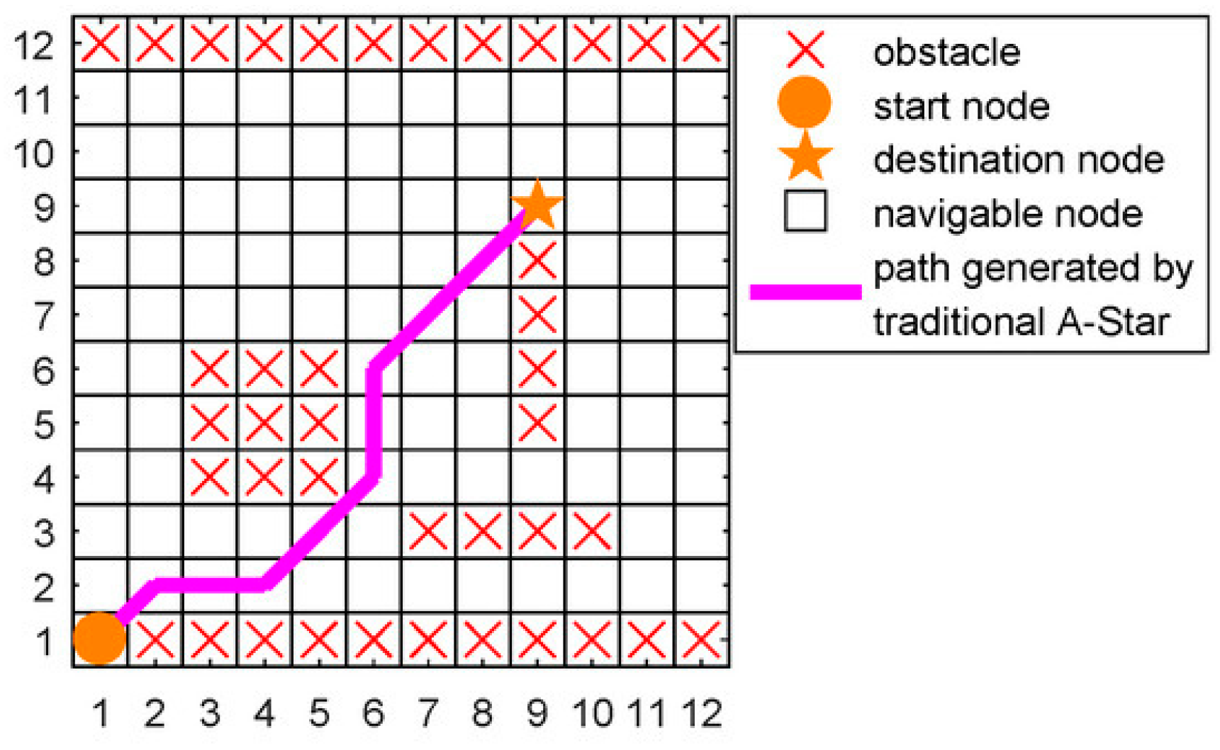
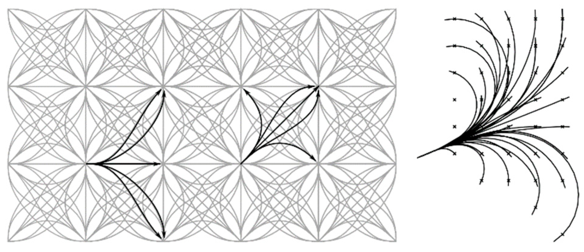
Scholars have conducted many studies on aircraft track planning methods. The planning algorithm based on graph search is the most widely used approach, which is represented by Dijkstra’s algorithm and the A* algorithm. Dijkstra’s algorithm is a graph search algorithm for finding the single-source shortest paths in a map, where the configuration space is approximated as a discrete cell space [2,3,4], as illustrated in Figure 1. As an extension of Dijkstra’s algorithm, the A* algorithm enables fast search of nodes because of the addition of heuristics, as demonstrated in Figure 2. The dynamic A* algorithm, field D* algorithm, and anytime repair A* algorithm were subsequently improved [5,6,7,8]. The state lattices algorithm is the development of basic graph search method, which combines a lattice that represents the object motion states with a discrete planning region and searches the state lattice to achieve object motion planning [9,10,11,12], as shown in Figure 3.
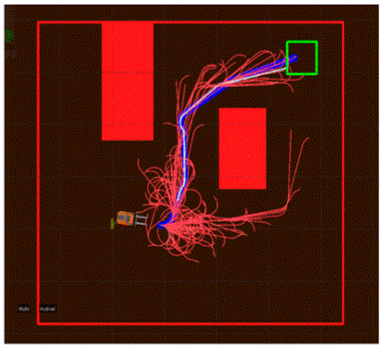
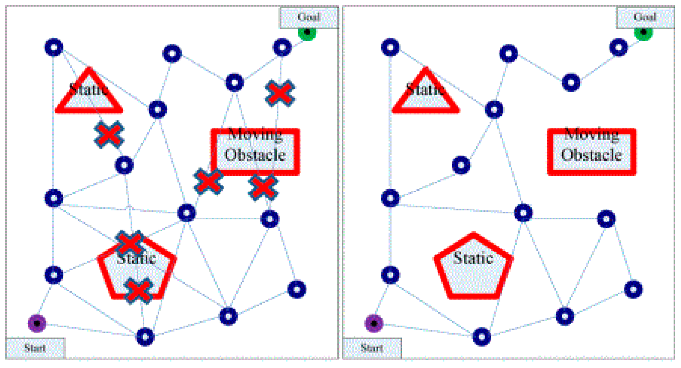
To solve temporal constraints that cannot be satisfied by deterministic methods, such as planning in a high-dimensional space, active and passive planning algorithms based on sampling were proposed [13,14,15]. Rapidly exploring random tree (RRT) is the most commonly used active algorithm that autonomously directs the search to blank areas and target points, as shown in Figure 4. Passive algorithms such as the probabilistic roadmap method (PRM) can generate a road network map from the starting point to the end point, but they need to be combined with a search algorithm to achieve optimal path selection [16,17,18,19], as illustrated in Figure 5.
With the development of computer-aided technology, techniques such as computer-aided geometric design are widely applied for path smoothing. The interpolation curve planning algorithm uses a known set of node sets that describes the global track to generate new datasets that describe a smoother path, considering information such as the continuous rows of the track, aircraft performance constraints, and the dynamic airspace environment [20]. Gyration curves allows defining trajectories where the curvature is linearly varying to be defined, thus allowing smooth transitions between straight line segments and curved line segments [21,22]; polynomial curves are usually used to satisfy constraints on their interpolation points and are effective in fitting location, angle, and curvature constraints [23,24,25]. The Bézier curve is a parametric curve that defines its shape depending on the control point, which has the advantage of low computational cost [26,27,28,29]. Spline curves are segmented polynomial parametric curves. Through subintervals, they can be represented by polynomial curves, B-spline curves, or gyration curves [30,31,32].
In recent years, the optimization method is the most studied approach to solve track planning problems. It usually considers the kinematic attribution of the aircraft with a set of cost matrices. The key to this optimization approach is the rational definition of cost function, which typically includes fuel consumption and time consumption, workload, and aircraft acceleration variation [33,34,35]. Moreover, intelligent optimization algorithms including the genetic algorithm, multi-intelligence collaborative reinforcement learning method, artificial bee colony algorithm, space–time flow approach, and machine learning have also been widely applied [36,37,38,39,40,41].
Optimal control and game theory are also used to solve the aviation conflict problem. Airspeed, heading, and latitude and longitude were mostly used as optimization parameters [42]. A three-layer learning neural network that only makes changes to the heading when conflict occurs was proposed to calculate the approximate optimal track [43]. The fuzzy algorithm establishes fuzzy rules based on driving experience to derive search results and shows superiority in dealing with path planning in unknown environments due to its insensitivity to moving object localization accuracy and its low dependence on the environment [44,45,46].
In summary, the existing track planning method mainly focuses on real-time conflict resolution with the objective of minimizing a single aircraft’s track length, while the impacts of other aircraft and the complex environment to the track planning are less considered. Nevertheless, the pilot, instead of the ground air traffic controller, is primarily responsible for the track planning task under the next-generation air transport system. The complex and time-varying airspace condition has a greater impact on the pilot’s track planning process.
Thus, this paper proposes a novel strategic air track planning method considering the minimization of conflict probability, which can help reduce the real-time conflict risk, especially in an airspace with high-density and high-traffic flow. To estimate the potential conflict probability of an aircraft, the proposed method is realized by generating the potential motion space of the aircraft. After the potential conflict probability is calculated, the air track planning can be conducted by taking the minimization of the conflict probability as one of the most important objectives. The proposed method features the ability to advance the task of conflict avoidance and therefore reduce the workload of the air controller and pilot in tactical aircraft track planning. Moreover, coordinated strategic air track planning has great potential to reduce aircraft delays and improve the efficiency of the whole air transport system.

3. Method

3.1. Generating Aircraft Potential Motion Space

In an ideal theoretical state, with the assumption that the travel origin of an aircraft can be determined, the spatial range that an aircraft can potentially reach at any moment after departure can be represented by a circle with the travel origin of the aircraft’s track as the center of the circle. The area within the range that the individual can reach under the time constraint is defined as the reachable area of the aircraft’s movement. The area of the potential track area expands with time and shows an increasing trend, and the spatial range that the individual can reach under the joint constraint of the starting point and the ending point is the convex set formed by the intersection of the two circles (one circle center on the starting point and another circle center on the ending point).
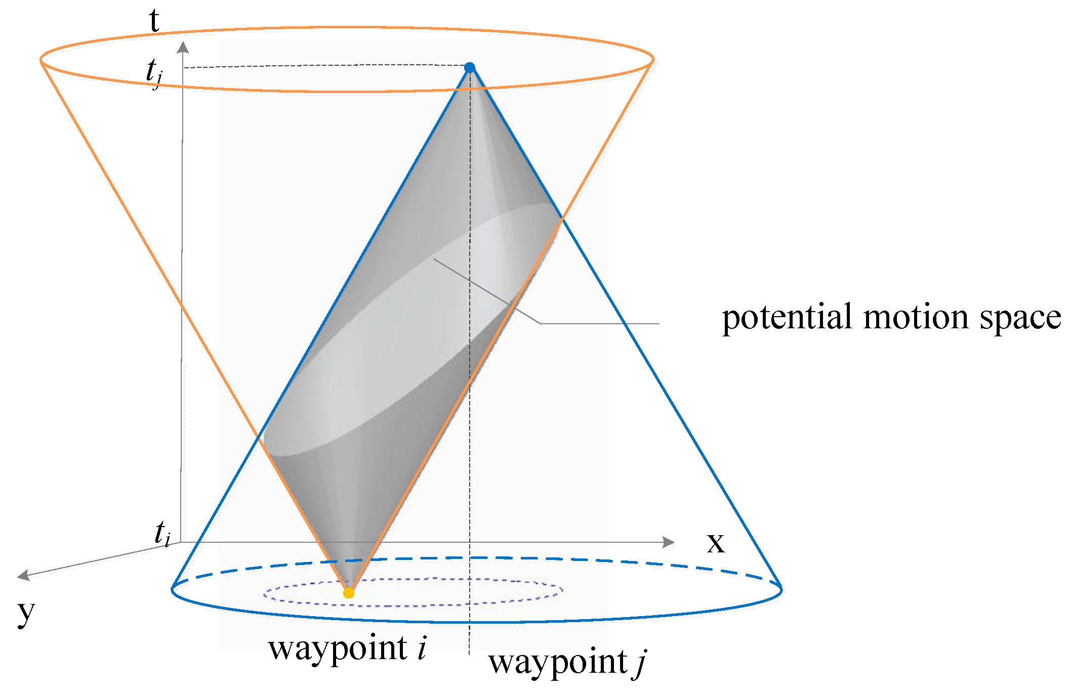
Projecting the above concept into three-dimensional (3D) space, we can obtain two pyramids formed by continuously changing reachable regions that contain temporal information, which are defined as the spatiotemporal motion space, as illustrated in Figure 6. The spatiotemporal motion space is a description of the possible spatial and temporal extent of future individual trips. The reachable spatiotemporal motion space reflects all the spatiotemporal regions that an individual can reach in time and space dimensions under the constraints of the known starting point, ending point, departure moment, ending moment, and maximum travel speed. Its boundary is the maximum spatiotemporal range that can be reached by an individual.
The potential motion space of an aircraft describes the set of all positions that the aircraft can reach and the corresponding arrival times. The intersection of the potential motion space of two aircrafts is defined as the potential conflict zone (PCZ) of the two aircrafts. The PCZ helps visually identify when the conflict will occur and the area where it is likely to occur. Aircrafts outside the PCZ do not have the possibility of conflict. When an aircraft enters the PCZ, a possibility of conflict arises.

3.2. Aircraft Potential Conflict Probability Estimation

Considering the time variation and uncertainty of the pilot’s will, the flight process of an aircraft can be considered a non-regular Brownian motion. Under the next-generation air transport system, the required route and the time to pass the waypoint when the aircraft is performing its mission are predetermined in the planning, and considering the limitation of the aircraft’s reachable domain, with reference to the method addressed in [47], this paper considers that the possibility of the aircraft being outside the potential motion space is zero; thus, a truncated distribution is used to represent the constraints of the reachable domain.
The truncated distribution is a conditional distribution obtained by truncating the range of the definition domain of the probability distribution. Specifically, the definition domain of the normal distribution is (−∞, +∞), which can be regarded as untruncated. If a range restriction is added to the values of X, then it can be regarded as conforming to the truncated normal distribution.
Any probability density function curve and the x-axis integration of the region are 1, so the truncation does not remove either side of the density function, while the shape of the curve also changes accordingly. However, in the truncated region, which is the area of the curve below the presence of 1, the value of the function outside the region is 0. The probability density function of a variable X is f(x), the definition of the domain is an infinite set, the cumulative distribution function is F(x), and the definition domain is restricted to a < xb. Then, its probability distribution at a given time is
T ( x ) = f ( x | a < x b ) = g ( x ) F ( b ) F ( a ) ,
g ( x ) = { f ( x ) , a x b ; 0 , x < a   o r   x > b
If at the moment t i an aircraft passes point i with coordinates ( x i ,   y i ) and point j with coordinates ( x j ,   y j ), then the flight plan specifies in advance the points through which the aircraft must pass and the time to pass each point to ensure that the aircraft can reach a point at the specified time, and the actual reachable domain of the aircraft is limited at the time level to some extent. According to the above equation, it follows that at a certain moment t (t ∈ [ t i , t j ]), subject to the limitation on the reachable domain of the aircraft, the position distribution of the aircraft is:
L ( x ( t ) ) = K ( x ( t ) ) K ( M x ( t ) K ( L x ( t ) ) ,
L ( y ( t ) | x ~ ( t ) ) = K ( y ~ ( t ) ) K ( M y ( t ) K ( L y ( t ) )
where:
M x ( t ) , L x ( t ) —the upper and lower boundaries of the airspace domain of potential aircraft movement in the x-axis.
M y ( t ) , L y ( t ) —the upper and lower boundaries of the airspace domain of potential aircraft movement in the y-axis.
K(x(t)), K(y(t))—obey the probability density function of N ( μ x , σ x 2 ( t ) ) and N ( μ y , σ y 2 ( t ) ) .
Supposing two aircrafts A and B have potential motion spaces represented as Space A and Space B, respectively, then the PCZ Space AB of these two aircrafts is calculated as follows:
S P A C E A Β = { S P A C E A , S P A C E B }
The above equation indicates that the PCZ is the intersection of the potential motion space of the two flight areas. In fact, whether a conflict occurs between two aircrafts also depends on the relationship between their spacing and the safety interval. Only when the spacing between two aircrafts is less than the safety interval can a conflict between these two aircrafts be considered to exist.
However, the actual conflict probability (ACP) of two aircrafts is not equal to the product of their respective potential conflict probabilities because the potential conflict spatiotemporal domain includes two forms: two potential motion spatiotemporal domains intersect, and one potential motion spatiotemporal domain contains another potential motion space–time domain. Even if both aircrafts are located in the PCZ, no risk of conflict exists if the separation between them is greater than the safety separation. Therefore, the probability that both aircrafts are within the potential conflict spatiotemporal domain and that their spacing is less than the safety interval is defined as the ACP between these two aircrafts. The ACP between aircrafts A and B can be calculated as
ACP = u = 1 n v = 1 n Prob AB ( u ,   v ) ,   u , v SPACE   AB
Prob AB = Prob A ( x u , y u , t u ) × Prob B ( x v , y v , t v )
where:
Prob A ( x u , y u , t u ) —the probability that aircraft A is located at point ( x u , y u , t u ) .
Prob B ( x v , y v , t v ) —the probability that aircraft B is located at point ( x v , y v , t v ) .
Point u—any point located in the PCZ between aircrafts A and B.
Point v—a point located in the PCZ between aircrafts A and B that is different from point u.
Similarly, the actual conflict probability of multiple aircrafts can be expressed by a similar formula to those above.

3.3. Improved Track Planning Method Considering Conflict Probability

This chapter is based on the grid method for modeling, and its process considers the following assumptions:
(1)
The uncertainty characteristics of each aircraft are the same and the uncertainties among aircraft are independent of each other.
(2)
The uncertainty does not change with time; that is, the uncertainty is always consistent during the planning process and no other variables appear.
(3)
With the assumption that the aircraft speed in the climb and descent phases cannot be controlled, only the aircraft in the cruise phase is considered for the track planning.
(4)
The aircraft can be considered a mass point with a negligible size to conduct the study.
(5)
Unpredictable off-site influence factors such as meteorology are not considered.
(6)
No special airspace is demarcated so that the aircraft cannot fly within its range.

3.3.1. Constraints and Objective Functions

The constraints to be met by the aircraft include the following:
(1)
Consistency must be met between the actual start and end points of the aircraft flight path and the start and end points of the planned track. To successfully complete the navigation task, the deviation between the flight’s start and end points and the planned start and end points of the track should be minimized and made consistent:
D ( ( ( X a , Y a ) ( X b , X b ) ) ) = 0
where ( X a , Y a )   are the coordinates of the start and end points of the track planning, and ( X b , Y b ) are the coordinates of the start and end points specified for the flight mission.
(2)
The rationing of flight fuel should meet the established requirements. The aircraft’s mission should meet the requirements of the actual scene and not exceed a certain limit of energy consumption,
L max L total 0
where:
L max —the maximum fuel consumption set for the aircraft during the mission.
L total —the fuel consumption of the track planning.
(3)
The flight time should meet the established requirements of the planning. The aircraft’s mission should meet the requirements of the actual scene,
t plan t total = 0
where t plan is the flight time set for the aircraft during the mission, and t total is the flight time of the track planning.
(4)
The minimum turning radius should correspond to the performance limitation. Due to maneuvering performance limitations, if the aircraft needs to make a turn and perform other operations during fight, its turning radius often cannot be less than a certain value. Therefore, the expression of the minimum constraint on the aircraft’s turning radius is
R i R min 0   ( i = 2 , , n )
where:
R i —the turning radius of the aircraft at the i-th turn.
R min —the maximum turning radius of the type of aircraft.
The specific value of R min should be derived by querying the BDDA database according to the type of aircraft.
(5)
The size of the steering angle is generally limited by the performance of the aircraft itself.
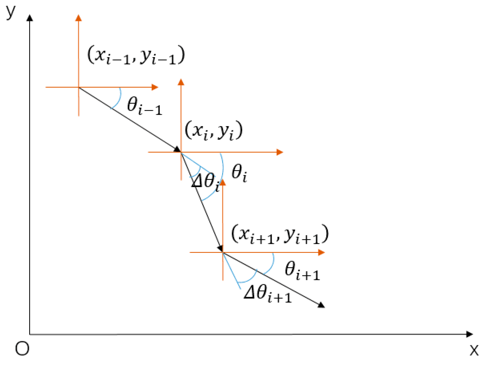
As shown in Figure 7, the schematic for calculating the turning angle of an aircraft track shows that the turning angle formula is the difference between the arctangent angle at the absolute coordinates of the current turn point and the arctangent angle of the previous turn point:
θ i 1 = arctan | y i 1 y i x i 1 x i |
θ i = arctan | y i + 1 y i x i + 1 x i |
Δ θ i = θ i
where:
θ i —coordinate arctangent of the current turning point.
θ i 1 —coordinate arctangent of last turning point.
Δ θ i —turning angle of the track.
The maximum steering angle is limited by the different types and performances of aircrafts but is generally not greater than 30°; that is, the constraints are:
30 Δ θ i 0
(6)
The flight speed does not exceed the maximum economic cruise speed of the type of aircraft. It should be pointed out that as a rule, the upper limit of an aircraft’s flight speed is determined by the power system for which it is designed. However, because civil aircrafts generally cruise at an economic cruise speed, it is rare to encounter a situation where the maximum theoretical performance speed of the aircraft needs to be mobilized. Therefore, this paper only starts from the upper limit of the economic cruise speed and ignores the maximum theoretical performance speed, which is the maximum possible speed of the aircraft during track planning:
V max V i 0
where V max is the maximum economic cruise speed set for this aircraft during the fight mission, and V i is the speed of the aircraft in each segment of the track planning obtained from the planning.
To ensure the superiority of the track planning, the following objectives are set in this paper:
(1)
The length of track planning should be as short as possible;
(2)
The speed changes of the aircraft should be as low as possible;
(3)
The deviation of the aircraft from the main track should be as little as possible;
(4)
Aircrafts should be prevented from entering special airspace or flight-restricted flight areas;
(5)
The probability of conflict between aircraft should be minimized.
The above point reflects the main performance of the track planning. In the process of track planning, different weights should be given to each index according to the different business objectives and the actual operation of airlines to meet the different operational purposes and requirements of airspace users in terms of efficiency, safety, and economy.
In summary, the proposed track planning model can be expressed as:
min C ( i ) = i = 1 n ( A 1 l i + A 2 Δ V i + A 3 P + A 4 Δ D )
h ( i ) = { D ( ( ( X a , Y a ) ( X b , X b ) ) ) t plan t track
G ( i ) = { L m a x L total R i R m i n 30 Δ θ i V m a x V i
where A 1 is the weight coefficient of the track length, A 2 is the weight coefficient represented by the number of speed changes, A 3 is the weight coefficient of the conflict probability, A 4 is the weight coefficient of deviation from the main track planning, t total is the total track length, Δ V is the number of speed changes, P is the conflict probability between aircrafts, Δ D is the distance from the main track, min C(i) is the objective function of this paper, and h(i), g(i) are the constraints of this paper.
The sum of A 1 ,   A 2 ,   A 3 , and   A 4 should be 1. In this paper, considering that the aircraft maintains the same speed throughout the whole process, the number of motion changes is the number of inflection points of the track at the planning place.
In the above-mentioned cost function, different objectives have significantly different magnitudes; for example, the length of the track is hundreds of kilometers, the number of speed changes is in units of time, and the probability of conflict is a decimal. It is a difficult task to add or subtract the values directly to ensure that the value of the objective function can be quantified and eliminate the influence of its magnitude on the results. Thus, this paper uses the normalization method to normalize the value of the track generation, as shown in Equation (20),
P 0 = P P min P max P min
where P is the value of the current factor, P min is the minimum unit factor, and P max is the maximum unit factor.
The parameter values of different purpose weight coefficients in the above objective function can be flexibly adjusted according to the actual situation of the aircraft’s flight objectives and the airline’s operational objective, and even other objectives can be added.
To solve this model, a three-layer algorithm that combines the global planning algorithm with improved ACA, local replanning algorithm with the D* algorithm, and the track smoothing algorithm is proposed in this paper.

3.3.2. The Improved ACA Combined with the D* Algorithm

ACA is one of the commonly used algorithms for path planning. In this paper, the grid method is used to model and improve the classical ACA. In the context of the space–time constraint, the operations of some parameters of the ACA need to be adjusted to fit the requirements of space–time path planning, including several aspects: the heuristic factor, the guidance factor, the pheromone update strategy, and the state transfer strategy.
(1)
Heuristic factor
In this paper, the design of the heuristic factor contains two cases. For points in special airspace, restricted airspace, or within the potential motion space of another aircraft, the heuristic factor should be as small as possible to encourage aircrafts to avoid these areas. For points in special airspace, restricted airspace, and outside the potential movement space of another aircraft, the heuristic function is designed to extend the distance between the point and these areas to guide the aircraft away from such potential conflict areas. The heuristic factor of point m can be calculated by the following equation:
ε m = s = 1 n 1 ( x m x s ) 2 + ( y m y s ) 2
η m = { 1 ε m 0.0001
where s denotes any point located in the potential motion space-time domain of another aircraft. ε m denotes the threat cost of point m, which is calculated as the sum of the reciprocal of the distances between point m and the points within the potential motion space of another aircraft. η m denotes the heuristic factor.
(2)
Guidance factor
The ant colony optimization algorithm searches for expansion points based on the state transfer probabilities, which can be deduced from the heuristic factors and pheromones. The differences between the heuristic values and the pheromone values are small in the initial iteration stage; thus, the search for expansion points easily falls into a local scope. Therefore, a guidance factor should be introduced in the state transfer function to guide the search to expand in the target direction. The guidance factor of node m can be expressed as:
d m D = ( x m x D ) 2 + ( y m y D ) 2
λ m = 1 d m D
where ( x D ,   y D ) represents the position of destination node, and λ m represents the guidance factor of node m.
(3)
Pheromone matrix and update strategy
According to the scale of the planning space, a pheromone matrix of order h × v × l is established. After each iteration, some of the pheromones are volatilized and 1 ρ pheromones are left behind. Therefore, the pheromone can be expressed as:
τ i j ( t + n ) = ρ τ i j ( t ) + ( 1 ρ ) Δ τ i j ( t )
Δ τ i j ( t ) = k = 1 m Δ τ i j k ( t )
Δ τ i j ( t ) best = { Q W n best ,   a b Tabu k ( N ) 0
where Δ τ i j ( t ) best denotes the optimal track of the N-th iteration. W n best denotes the cost of the N-th iteration, which is the cost function in the previous section. Q denotes the pheromone enhancement.
To accelerate the convergence of the algorithm, only the pheromone of the optimal path is enhanced after each iteration.
(4)
State transfer strategy
In the initial iteration, the pheromones on each path are the same. The probability of ant k moving from node a to node b in the Nth iteration can be calculated with Equation (28):
P i j k ( t ) = { [ τ i j ( t ) ] α [ η i j ( t ) ] β [ λ i j ( t ) ] γ s T allowed , k [ τ i s ( t ) ] α [ η i s ( t ) ] β [ λ i s ( t ) ] γ ,   j , s T allowed , k   0 ,   e l s e
where T allowed ,   k denotes the list composed of each node that ant k passes through at the t-th iteration, α denotes the pheromone weights, β denotes the heuristic factor weights, and γ denotes the guidance factor weights.
In summary, the improved ACA under 3D raster proceeds as follows:
(1)
The surrounding airspace environment information is extracted, the special airspace and flight restricted airspace are rasterized, and the adjacency matrix of raster cells is established.
(2)
The maximum number of cycles is set, and the starting position of ants, cycle count counter, step counter, pheromone matrix, and the values of each parameter are initialized.
(3)
According to the ant’s current location grid and grid cell adjacency matrix, the adjacent free grids are added as allowed, and the state transfer probability of each adjacent free grid is calculated according to the pheromone, guidance, and heuristic factors.
(4)
The ants are moved to the grid with the highest transfer probability, and the grid number is added to the taboo table.
(5)
If the ant has not reached the target grid, then step 3 is repeated.
(6)
The optimal path with the lowest cost is recorded. Whether the two track points on the optimal path meet the speed constraint is checked, and the track points that meet the constraint are added to the actual set of track points.
(7)
If the actual set of track points is empty, then a suboptimal path is selected, and step 7 is repeated.
(8)
The pheromone on the path with the lowest cost is updated.
(9)
The number of cycles is updated. When the number of cycles is greater than the maximum number of cycles, the search stops and the optimal set of track points is achieved. Otherwise, the taboo table is cleared, and the execution is transferred to step 3.
The D* algorithm originated from the A* algorithm, which was initially a 2D graphical optimization-seeking algorithm. The A* algorithm takes the departure point as the starting point of the path planning, and it starts to optimize from the starting point to calculate the track cost from the current point to the departure point. Thus, the node information of the previous track planning calculation is not actually used when this algorithm is applied. In contrast, the D* algorithm starts from the end point to calculate the cost of the track from the current node to the end point. Thus, when this algorithm is used to deal with temporary obstacles or special airspace avoidance, it effectively reduces a large number of repeated calculations and improves the overall efficiency of the algorithm.
The D* algorithm is efficient and can adapt to environmental changes. However, the algorithm has more nodes in the initial computation of track traversal, thus being slower and less efficient. Its search volume is extremely large if a large amount of environmental information is available, thus posing higher demands on the computer and taking a longer time to solve.
Thus, this paper proposes an improved hybrid D* ACA by combining the D* algorithm with the ACA according to the actual situation and the needs of track planning. The improved hybrid D* ACA is able to avoid sudden obstacles and therefore has the ability to interact with temporary obstacles or special airspace in complex dynamic environments. In addition, the algorithm can reuse previous planning results and perform local path replanning based on global planning, which greatly reduces the cost of the algorithm.
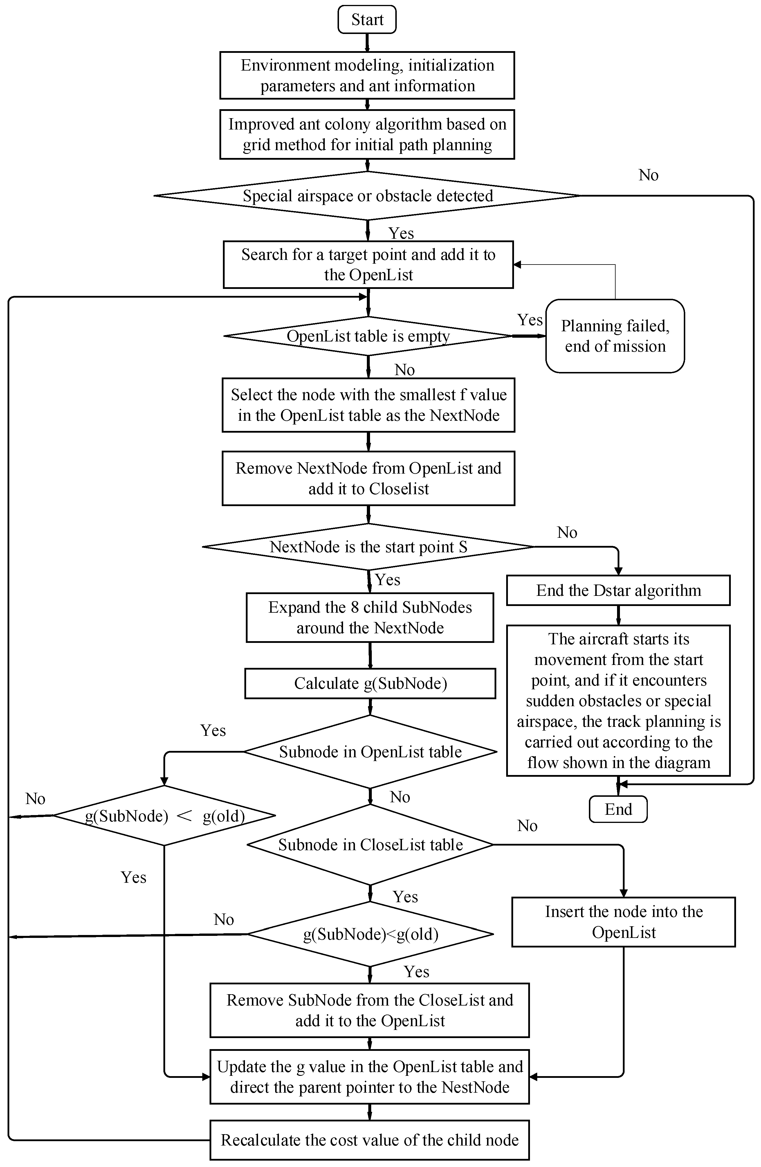
The flowchart of the improved hybrid D* ACA is shown in Figure 8.
When a track is planned, the origin point of the map model is set to s and the destination point to d. The “open list” and “close list” are created as empty linked lists to store information about the road nodes.
The process of the improved hybrid algorithm is as follows:
(1)
The parameters of the improved hybrid algorithm are set and adjusted, including the total number of nodes, the number of ant iterations, the initial pheromone P, and the weight of each coefficient.
(2)
The ant colony should start to iterate on path optimization and plan the initial path.
(3)
Detect if there are any temporary obstacles or special airspace and their location information; if yes, then the search is expanded from the end point d, and d is added to the “open list”. Otherwise, the algorithm ends.
(4)
Check if the “open list” table is empty. If yes, then the planning process stops; otherwise, the node with the lowest cost estimate in the open list table is selected as the next node to go to the next step. The node is then deleted from the “open list” table and added to the “close list”. Then, check if it is the starting node. If yes, the track planning process ends, and step (6) is performed. Otherwise, perform step (5).
(5)
The neighboring nodes of the next node are found and set as the child node. Their corresponding track cost values are calculated, and the next node is its parent node. The track cost value of the new node and the old node in the “open list” are compared. If the track cost of the new node is lower, then recalculation is performed, and the path is updated. The parent node is changed to the child of the next node, and step (4) is performed.
(6)
When the aircraft detects a temporary obstacle or special airspace again, the above steps are repeated.
(7)
The requested track is obtained, and the algorithm is completed.

3.4. Bézier Curve Based on the Track Smoothing Algorithm

Given that the path generated by the track planning method contains multiple directed line segments, in actual flight, the improper articulation of the slope of the track’s straight lines will cause the aircraft to make a large turn, causing the pilot’s driving deviation and confusion of the start and end of the turn. At the same time, considering that the steering angle should be reduced as much as possible under the characteristics of the aircraft itself, during the solution process, more smoothness is needed for the existing paths because the straight-line segments will inevitably produce some stiff turns, thus increasing the difficulty of real-time realization.
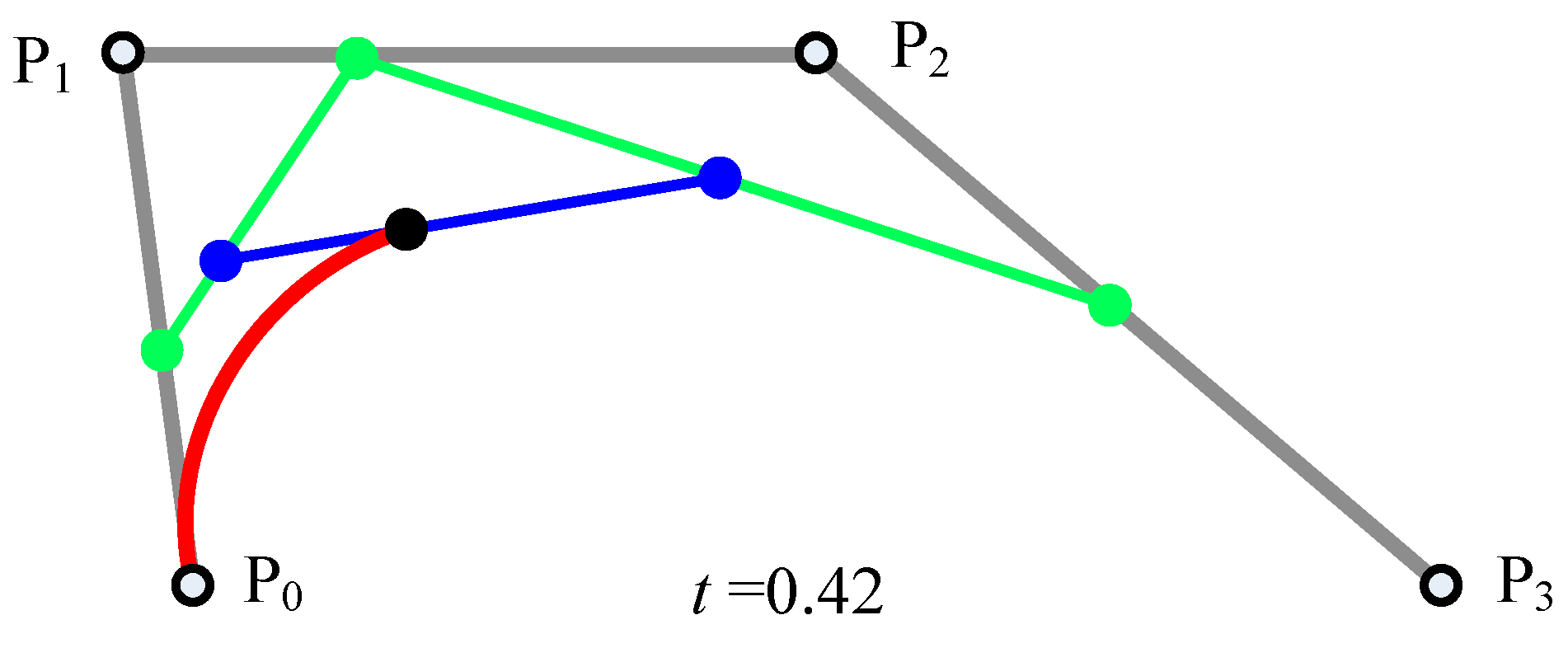
The smoothing method used in this paper is based on the principle of the Bézier curve. When Bézier curves are used for path planning purposes, three curves are commonly used for this purpose because at this point, the curve’s speed and acceleration at the point of change remain essentially the same before and after the change, and its expression is:
B ( t ) = P 0 ( 1 t ) 3 + 3 P 1 t ( 1 t ) 2 + 3 P 2 t 2 ( 1 t ) + P 3 t 3
where B ( t ) denotes the coordinates of the aircraft at time t, P 0 denotes the beginning of the voyage, P 2 denotes the end of the voyage, and 1 and 2 represent the two control points during the voyage, as illustrated in Figure 9.
In sum, the process of the introduced smoothing algorithm is as follows:
(1)
Step 1: The maximum value of allowable steering angle is set to meet the performance and mission requirements of the aircraft.
(2)
Step 2: Path corners are searched sequentially, path corners that exceed the critical value are found, and then step 6 is performed if the destination has been reached.
(3)
Step 3: A distance along the original track and the track is extended after the turn, and the starting and ending points and control points of the constructed Bézier curve are selected to form its characteristic polygon.
(4)
Step 4: The control points are connected, and whether the line is located within the obstacle or overlaps with the neighboring tracks is checked. If not, then step 3 is performed; otherwise, step 5 is performed.
(5)
Step 5: The original control node or the track turning point of the curve is recorded, and if it is detected as a usable control point, then a suitable t is selected to construct a Bézier curve and added to the planned track; if the detection result is an unavailable or has an unrealistic curve start and end or control point, then the track is not changed, and steps 2–4 are repeated.
(6)
Step 6: The algorithm is terminated.
In the application of the final smoothing algorithm of the track planning, the above algorithm can be called many times according to the needs of the mission objectives and the requirements of the track to gradually reduce the flight turn angle so that the smoothness of the track is higher and more harmonious. Considering that the simulated aircraft models are similar and the economic cruise speed is the same, the maximum turning angle is 30°, and a suitable t value should be selected according to the actual situation in the example analysis.

4. Experimental Verification

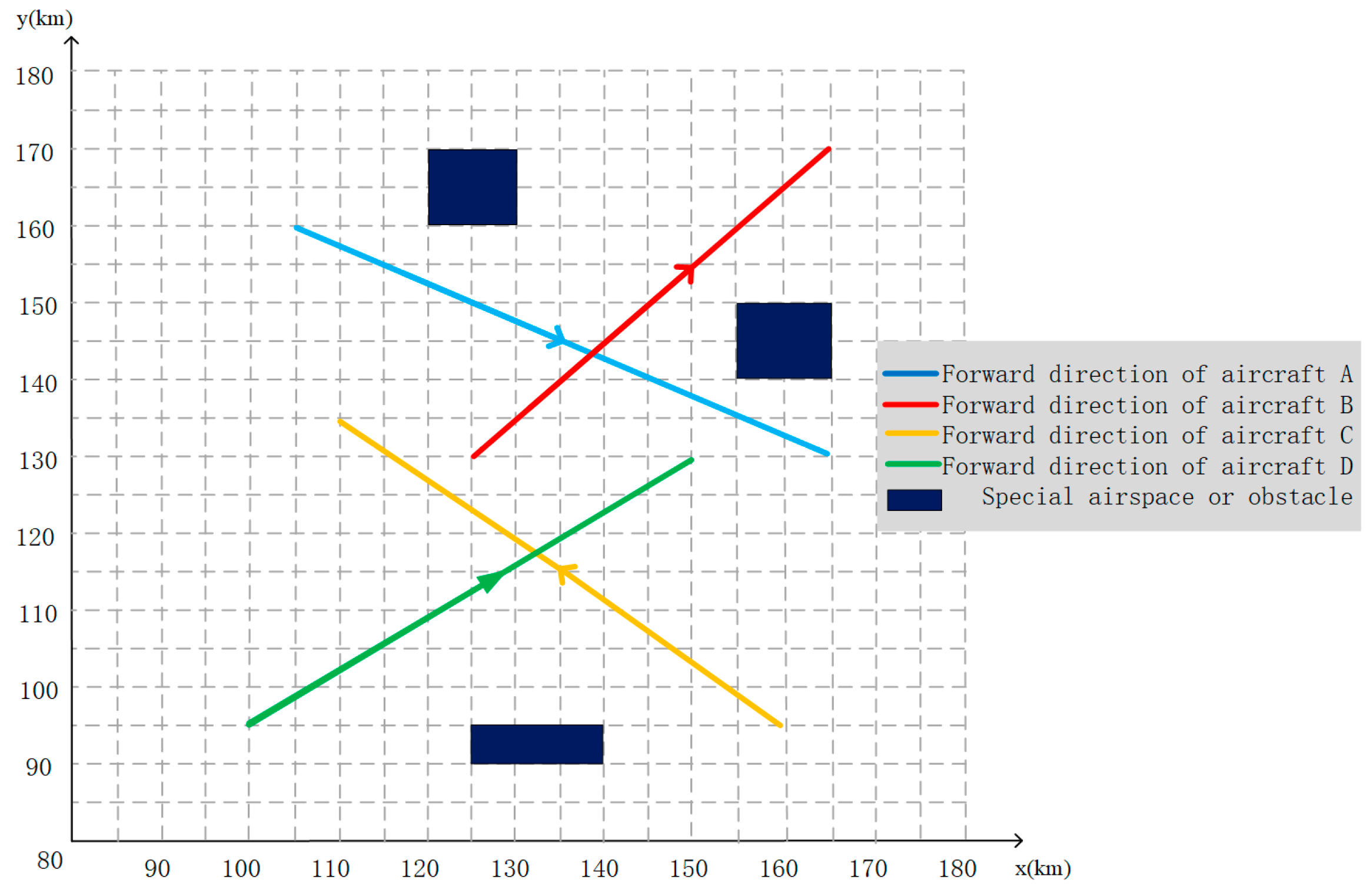
To illustrate the proposed aircraft track planning method, this study assumes a four-aircraft situation. The real-time flight plan data are from Chinese Civil Aviation website, and the details of the flight plan are listed in Table 1, in which origin time and destination time represent the planned times of passing the starting and ending waypoints.
Three groups of special airspace or temporary obstacles that appeared only during fixed hours were selected, and the time and location of their appearance are shown in Table 2.
The simplified diagram of the aircrafts, the special airspace, and temporary obstacles is shown in Figure 10.
The three-layer algorithm described above is selected for the track planning, and the global planning of the track is first targeted at reducing the conflicts between aircrafts, with the parameters shown in Table 3.
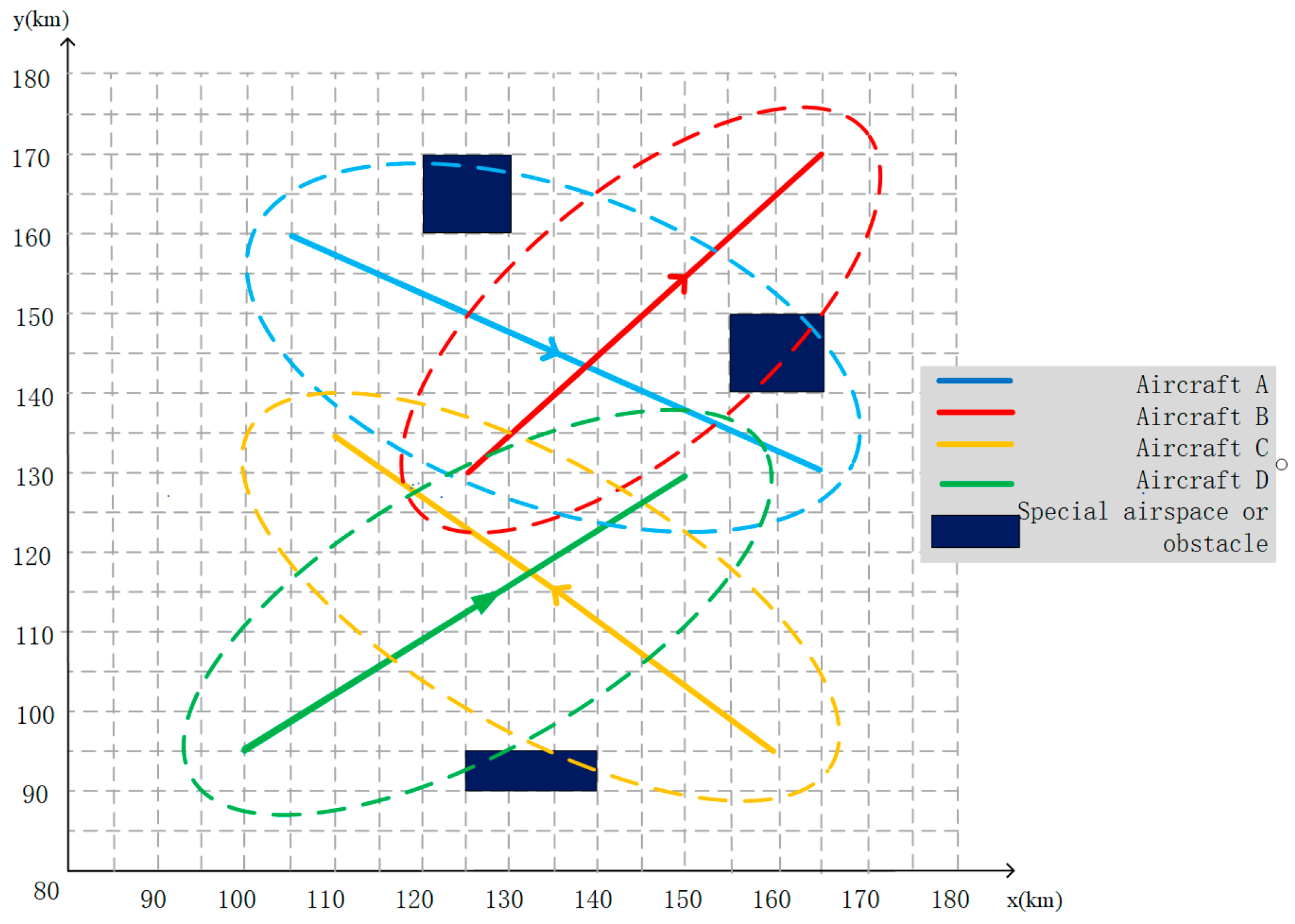
A schematic of the potential motion space of the four aircrafts is shown in Figure 11.
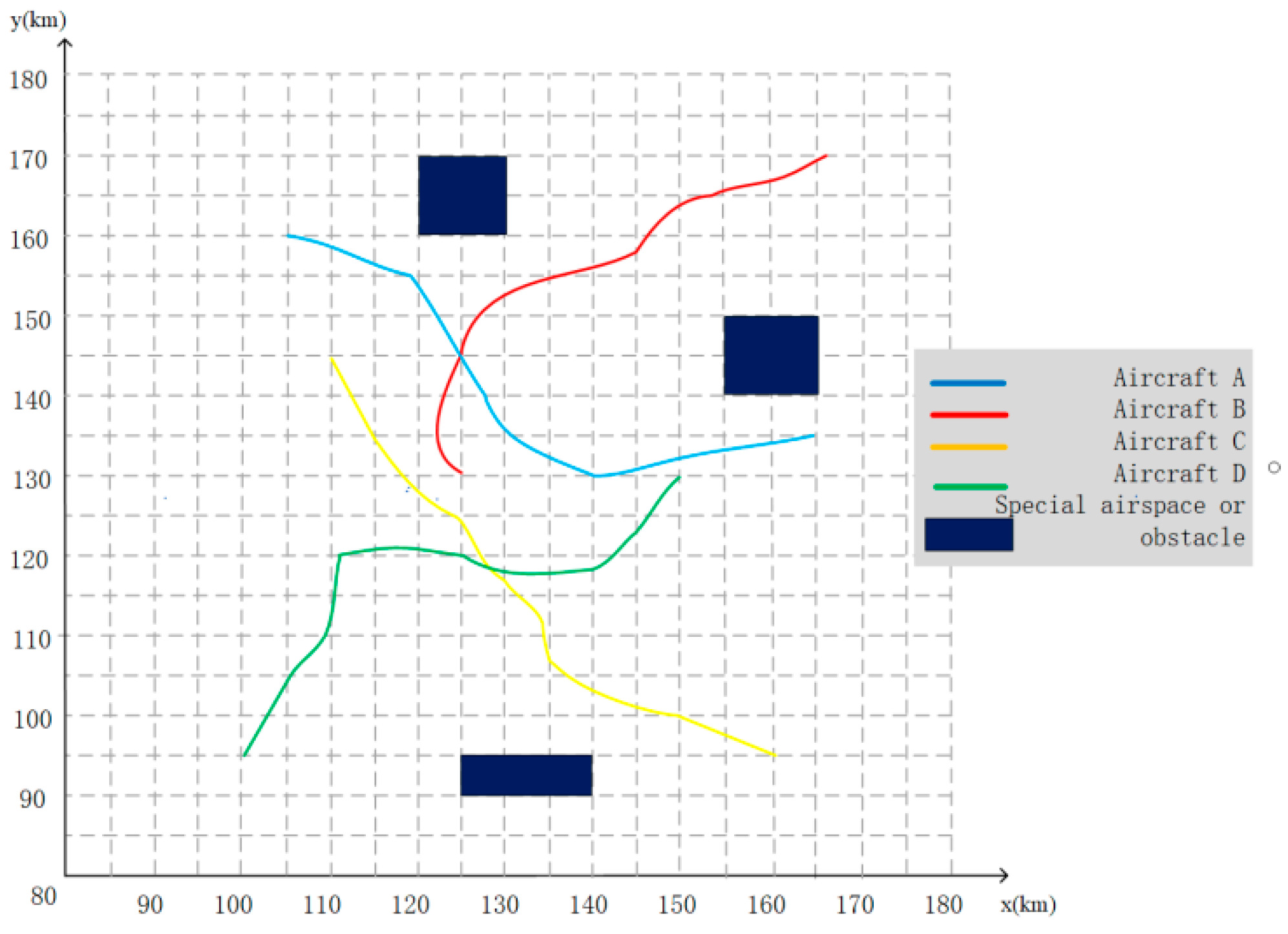
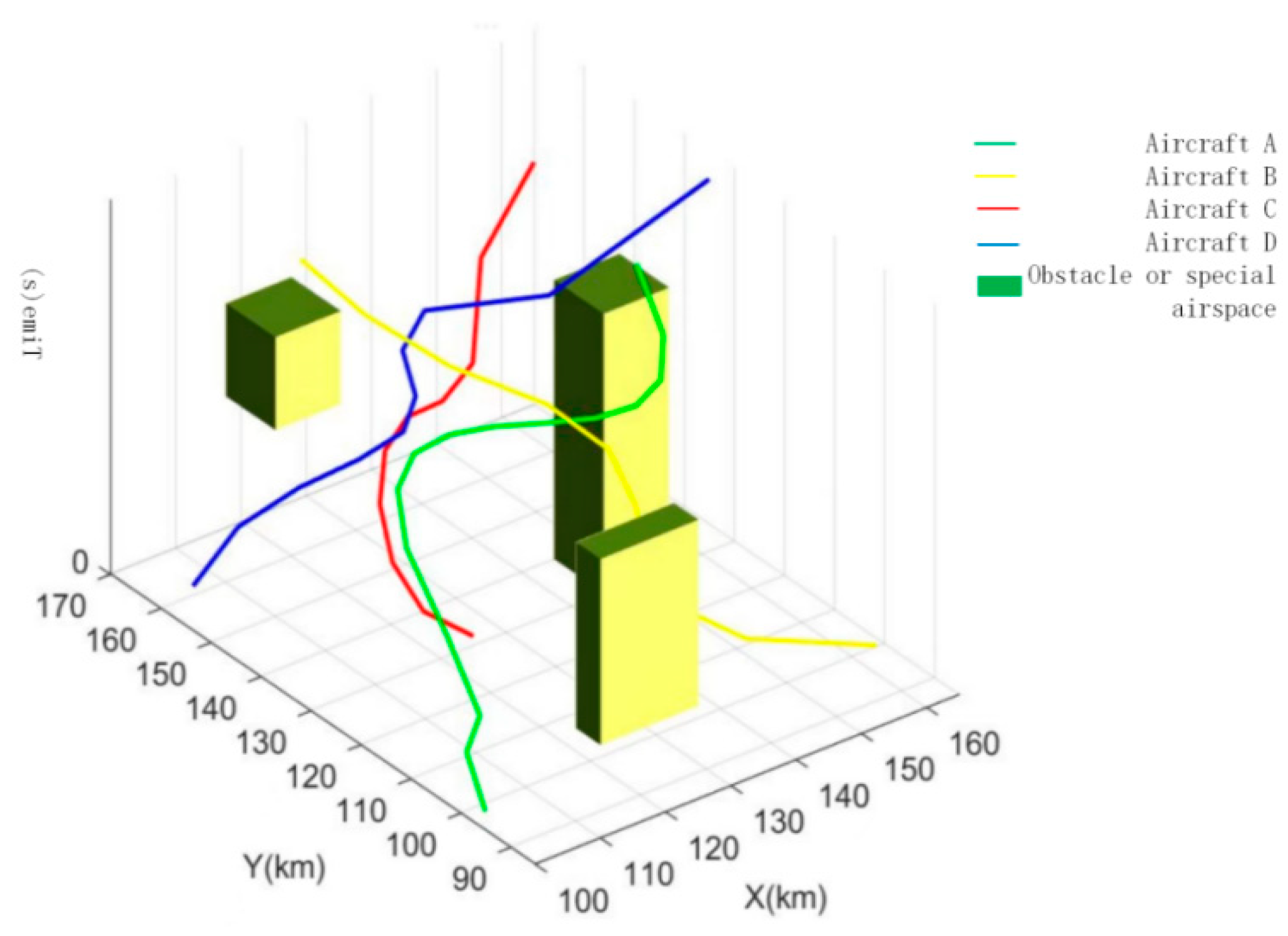
The track planning results after the second layer of the D* algorithm is used are shown in Figure 12 and Figure 13.
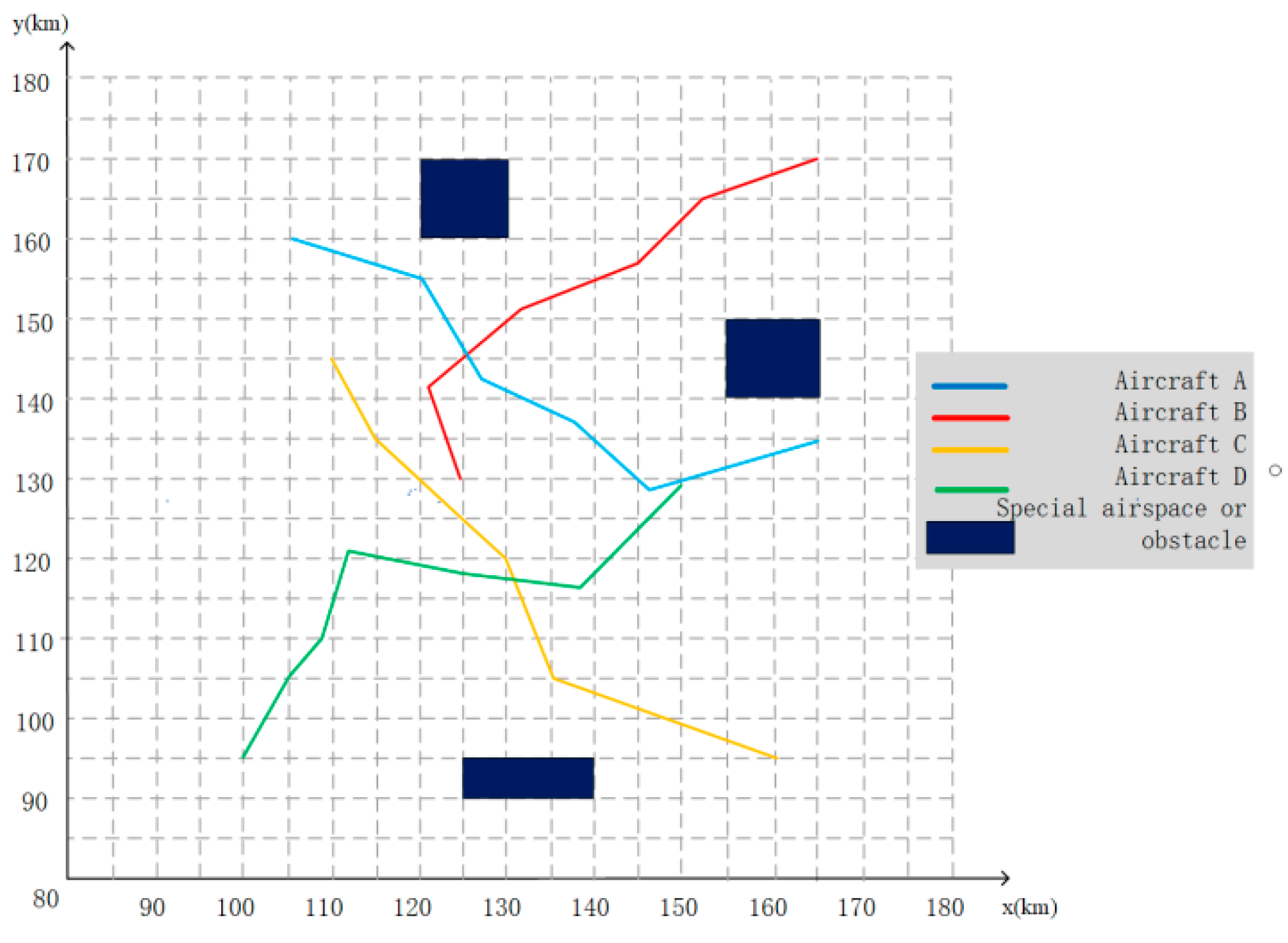
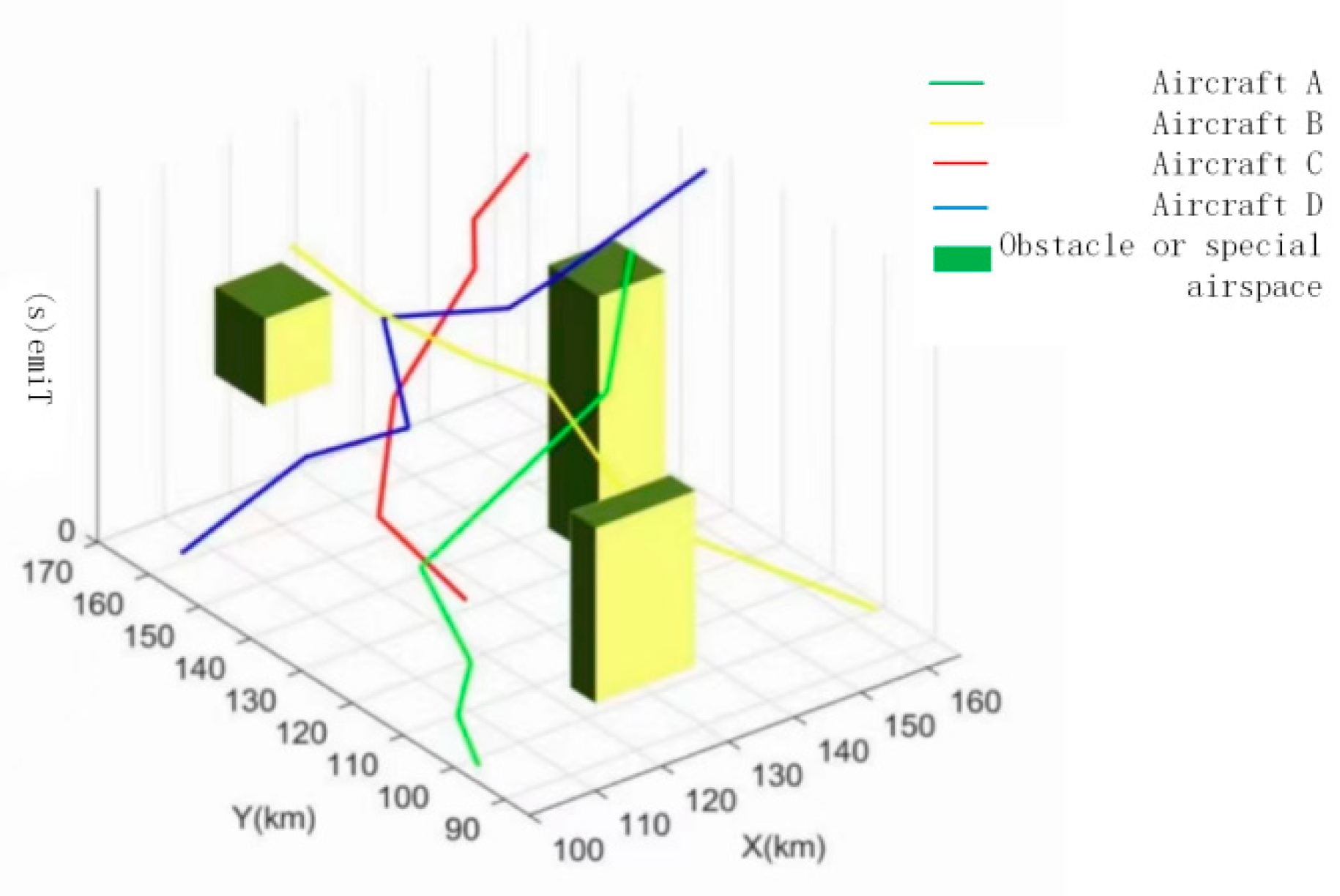
The above planning results are processed by the track smoothing algorithm, and the obtained 2D and 3D track maps are shown in Figure 14 and Figure 15.
Table 4 shows the actual track lengths and cost tables for the four aircrafts.
As shown by the above table, the actual track lengths of the four aircrafts do not change too much compared with the original starting and ending distances, while the conflicts between aircrafts are reduced, effectively avoiding the conflicts of special airspace and obstacles that appear only at specific time periods and in specific areas, as well as improving the smoothness of the track. Thus, performing aircraft track planning has some strategic significance for airlines.

5. Conclusions

In this paper, the problem of aircraft track planning is modeled by the grid method by considering conflict probability, which aims to achieve systematic aircraft track planning for multiple aircrafts in a complex context while avoiding special airspace and obstacles as much as possible and reducing aircraft conflicts at the same time.
First, this paper introduces the concept of the potential motion space of aircrafts and the calculation method of conflict probability, thus providing a theoretical basis for the construction of the objective function. Subsequently, this paper introduces the scenario assumptions, constraints, and objective functions, which are calculated by combining various aspects such as the number of speed changes, the deviation degree of the aircraft, and the track planning length to minimize the track planning cost of the aircraft system under complex scenarios. After that, this paper adopts the grid method for modeling and improves the classical ACA in terms of the heuristic factor, guidance factor, pheromone update strategy, and state transfer strategy, and proposes a 4D track planning algorithm based on the improved grid method. The D* algorithm is used to generate a track that avoids conflict between aircrafts and special airspace or temporary obstacles with uncertainty in time and space and introduces a smoothing algorithm based on Bézier curves. Finally, an experimental example of real airspace and four aircraft is presented to illustrate and verify the proposed track planning method.
On the basis of the proposed method, a novel weight matrix of cost function and coordinated strategic air track planning can be further studied to achieve a balance between the airline’s operating benefits and the efficiency of the entire air traffic system.

Author Contributions

Conceptualization, Y.Z. and S.H.; data curation, Y.M.; methodology, R.L., Y.Z.; validation, C.X. and W.L.; resources, Y.Z.; writing—original draft preparation, S.H. and C.X.; writing—review and editing, W.L. and R.L.; visualization, C.X. and Y.M.; supervision, S.H. and R.L.; funding acquisition, S.H. and R.L. All authors have read and agreed to the published version of the manuscript.

Funding

The authors also would like to acknowledge the financial support from the National Natural Science Foundation of China (Grant NO. 52105011 and Grant NO. 52102410), the Young Innovative Talents Project of Guangdong Province (Grant NO. 2021KQNCX071 and Grant NO. 2021KQNCX073), the Tertiary Education Scientific research project of Guangzhou Municipal Education Bureau (Grand NO. 202235334), and the Basic and Applied Basic Research Projects of Guangzhou (Grand NO. SL2023A04J00685 and SL2023A04J00686).

Data Availability Statement

The data used to support the findings of this study are available from the corresponding author upon request.

Acknowledgments

The authors acknowledge the anonymous reviewers for their valuable comments and suggestions.

Conflicts of Interest

The authors declare that there are no conflicts of interest regarding the publication of this paper.

References

  1. Zeng, W.; Chu, X.; Xu, Z.; Liu, Y.; Quan, Z. Aircraft 4D Trajectory Prediction in Civil Aviation: A Review. Aerospace 2022, 9, 91. [Google Scholar] [CrossRef]
  2. Li, Q.; Zeng, Z.; Yang, B.; Zhang, T. Hierarchical route planning based on taxi gps-trajectories. In Proceedings of the 17th International Conference on Geoinformatics, Fairfax, VA, USA, 12–14 August 2009; pp. 1–5. [Google Scholar]
  3. LaValle, S.M. Planning Algorithms; Cambridge University Press: New York, NY, USA, 2006. [Google Scholar]
  4. Hwang, J.Y.; Kim, J.S.; Lim, S.S.; Park, K.H. A fast path planning by path graph optimization. IEEE Trans. Syst. Man Cybern. Part A Syst. Hum. 2003, 33, 121–129. [Google Scholar] [CrossRef]
  5. Liu, C.; Mao, Q.; Chu, X.; Xie, S. An improved A-star algorithm considering water current, traffic separation and berthing for vessel path planning. Appl. Sci. 2019, 9, 1057. [Google Scholar] [CrossRef] [Green Version]
  6. Han, X.; Han, Z.; Yue, G. Path planning algorithm of disaster relief UAV based on optimized A*. Comput. Eng. Appl. 2020, 2, 232–238. [Google Scholar]
  7. Dolgov, D.; Thrun, S.; Montemerlo, M.; Diebel, J. Path planning for autonomous vehicles in unknown semi-structured environments. Int. J. Robot. Res. 2010, 29, 485–501. [Google Scholar] [CrossRef]
  8. Miller, I.; Campbell, M.; Huttenlocher, D.; Kline, F.R.; Nathan, A.; Lupashin, S.; Catlin, J.; Schimpf, B.; Moran, P.; Zych, N.; et al. Team Cornell’s Skynet: Robust perception and planning in an urban environment. J. Field Robot. 2008, 25, 493–527. [Google Scholar] [CrossRef] [Green Version]
  9. McNaughton, M.; Urmson, C.; Dolan, J.M.; Lee, J.W. Motion planning for autonomous driving with a conformal spatiotemporal lattice. In Proceedings of the 2011 IEEE International Conference on Robotics and Automation, Shanghai, China, 9–13 May 2011; pp. 4889–4895. [Google Scholar]
  10. Ziegler, J.; Stiller, C. Spatiotemporal state lattices for fast track planning in dynamic on-road driving scenarios. In Proceedings of the IEEE/RSJ International Conference on Intelligent Robots and Systems, St. Louis, MO, USA, 10–15 October 2009; pp. 1879–1884. [Google Scholar]
  11. Pivtoraiko, M.; Kelly, A. Efficient constrained path planning via search in state lattices. In Proceedings of the International Symposium on Artificial Intelligence, Robotics, and Automation in Space, Pasadena, CA, USA, 5–8 September 2005; pp. 1–7. [Google Scholar]
  12. Howard, T.M.; Green, C.J.; Kelly, A.; Ferguson, D. State space sampling of feasible motions for high-performance mobile robot navigation in complex environments. J. Field Robot. 2008, 25, 325–345. [Google Scholar] [CrossRef]
  13. Anderson, S.J.; Karumanchi, S.B.; Iagnemma, K. Constraint-based planning and control for safe, semi-autonomous operation of vehicles. In Proceedings of the IEEE Intelligent Vehicles Symposium, Madrid, Spain, 3–7 June 2012; pp. 383–388. [Google Scholar]
  14. Hwan, J.J.; Cowlagi, R.V.; Peters, S.C.; Karaman, S.; Frazzoli, E.; Tsiotras, P.; Iagnemma, K. Optimal motion planning with the half-car dynamical model for autonomous high-speed driving. In Proceedings of the 2013 American Control Conference, Washington, DC, USA, 17–19 June 2013; pp. 188–193. [Google Scholar]
  15. Kavraki, L.E.; Svestka, P.; Latombe, J.C.; Overmars, M.H. Probabilistic roadmaps for path planning in high-dimensional configuration spaces. IEEE Trans. Robot. Autom. 1996, 12, 566–580. [Google Scholar] [CrossRef] [Green Version]
  16. Furgale, P.; Schwesinger, U.; Rufli, M.; Derendarz, W.; Grimmett, H.; Mühlfellner, P.; Wonneberger, S.; Timpner, J.; Rottmann, S.; Li, B. Toward automated driving in cities using close-to-market sensors: An overview of the v-charge project. In Proceedings of the IEEE Intelligent Vehicles Symposium, Gold Coast, QLD, Australia, 23–26 June 2013; pp. 809–816. [Google Scholar]
  17. Ryu, J.H.; Ogay, D.; Bulavintsev, S.; Kim, H.; Park, J.S. Development and experiences of an autonomous vehicle for high-speed navigation and obstacle avoidance. In Frontiers of Intelligent Autonomous Systems; Springer: Berlin/Heidelberg, Germany, 2013; pp. 105–116. [Google Scholar]
  18. Karaman, S.; Frazzoli, E. Sampling-based algorithms for optimal motion planning. Int. J. Robot. Res. 2011, 30, 846–894. [Google Scholar] [CrossRef] [Green Version]
  19. Karaman, S.; Walter, M.R.; Perez, A.; Frazzoli, E.; Teller, S. Anytime motion planning using the RRT. In Proceedings of the IEEE International Conference on Robotics and Automation, Shanghai, China, 9–13 May 2011; pp. 1478–1483. [Google Scholar]
  20. Hsieh, M.F.; Ozguner, U. A parking algorithm for an autonomous vehicle. In Proceedings of the IEEE Intelligent Vehicles Symposium, Eindhoven, The Netherlands, 4–6 June 2008; pp. 1155–1160. [Google Scholar]
  21. Broggi, A.; Medici, P.; Zani, P.; Coati, A.; Panciroli, M. Autonomous vehicles control in the VisLab intercontinental autonomous challenge. Annu. Rev. Control 2012, 36, 161–171. [Google Scholar] [CrossRef]
  22. Brezak, M.; Petrović, I. Real-time approximation of clothoids with bounded error for path planning applications. IEEE Trans. Robot. 2013, 30, 507–515. [Google Scholar] [CrossRef]
  23. Petrov, P.; Nashashibi, F. Modeling and nonlinear adaptive control for autonomous vehicle overtaking. IEEE Trans. Intell. Transp. Syst. 2014, 15, 1643–1656. [Google Scholar] [CrossRef] [Green Version]
  24. Glaser, S.; Vanholme, B.; Mammar, S.; Gruyer, D.; Nouveliere, L. Maneuver-based track planning for highly autonomous vehicles on real road with traffic and driver interaction. IEEE Trans. Intell. Transp. Syst. 2010, 11, 589–606. [Google Scholar] [CrossRef]
  25. Keller, C.G.; Dang, T.; Fritz, H.; Joos, A.; Rabe, C.; Gavrila, D.M. Active pedestrian safety by automatic braking and evasive steering. IEEE Trans. Intell. Transp. Syst. 2011, 12, 1292–1304. [Google Scholar] [CrossRef] [Green Version]
  26. Rastelli, J.P.; Lattarulo, R.; Nashashibi, F. Dynamic track generation using continuous-curvature algorithms for door to door assistance vehicles. In Proceedings of the IEEE Intelligent Vehicles Symposium, Dearborn, MI, USA, 8–11 June 2014; pp. 510–515. [Google Scholar]
  27. Pérez, J.; Godoy, J.; Villagrá, J.; Onieva, E. Trajectory generator for autonomous vehicles in urban environments. In Proceedings of the IEEE International Conference on Robotics and Automation, Karlsruhe, Germany, 6–10 May 2013; pp. 409–414. [Google Scholar]
  28. Han, L.; Yashiro, H.; Nejad, H.T.N.; Do, Q.H.; Mita, S. Bézier curve based path planning for autonomous vehicle in urban environment. In Proceedings of the IEEE Intelligent Vehicles Symposium, La Jolla, CA, USA, 21–24 June 2010; pp. 1036–1042. [Google Scholar]
  29. Liang, Z.; Zheng, G.; Li, J. Automatic parking path optimization based on Bézier curve fitting. In Proceedings of the IEEE International Conference on Automation and Logistics, Zhengzhou, China, 15–17 August 2012; pp. 583–587. [Google Scholar]
  30. Berglund, T.; Brodnik, A.; Jonsson, H.; Staffanson, M.; Soderkvist, I. Planning smooth and obstacle avoiding B-spline paths for autonomous mining vehicles. IEEE Trans. Autom. Sci. Eng. 2009, 7, 167–172. [Google Scholar] [CrossRef] [Green Version]
  31. Thrun, S.; Montemerlo, M.; Dahlkamp, H.; Stavens, D.; Aron, A.; Diebel, J.; Mahoney, P. Stanley: The robot that won the Darpa Grand Challenge. J. Field Robot. 2006, 23, 661–692. [Google Scholar] [CrossRef]
  32. Bacha, A.; Bauman, C.; Faruque, R.; Fleming, M.; Terwelp, C.; Reinholtz, C.; Webster, M. Odin: Team victortango’s entry in the darpa urban challenge. J. Field Robot. 2008, 25, 467–492. [Google Scholar] [CrossRef]
  33. Radio Technical Commission for Aeronautics (RTCA). Minimum Operation Performance Standards for Traffic Alert and Collision Avoidance System II(TCAS II); Document RTCA/DO-185; RTCA: Washington, DC, USA, 2013. [Google Scholar]
  34. Alonso-Ayuso, A.; Escudero, L.F.; Martín-Campo, F.J. A mixed 0–1 nonlinear optimization model and algorithmic approach for the collision avoidance in ATM: Velocity changes through a time horizon. IEEE Trans. Intell. Transp. Syst. 2002, 39, 3136–3146. [Google Scholar] [CrossRef]
  35. Omer, J. A space-discretized mixed-integer linear model for air conflict resolution with speed and heading maneuvers. Comput. Oper. Res. 2015, 58, 75–86. [Google Scholar] [CrossRef] [Green Version]
  36. Zhou, Q.; Zhang, R.; Suo, X. Track planning for UAV with time restriction. Aviat. Comput. Technol. 2016, 46, 93–97. [Google Scholar]
  37. Yang, Z. Bio-Inspired 4D Trajectory Generation for Multi-UAV Cooperation; Zhejiang University: Zhejiang, China, 2016. [Google Scholar]
  38. Hu, Z. Research on Some Key Techniques of UAV Path Planning Based on Intelligent Optimization Algorithm; Nanjing University of Aeronautics and Astronautics: Nanjing, China, 2011. [Google Scholar]
  39. Chiang, Y.; Klosowski, J.T.; Lee, C.; Mitchell, J.S. Geometric algorithms for conflict detection/resolution in air traffic management. In Proceedings of the 36th IEEE Conference on Decision and Control, San Diego, CA, USA, 12 December 1997; pp. 1–12. [Google Scholar]
  40. Xu, Z.; Zeng, W.; Chu, X.; Cao, P. Multi-aircraft trajectory collaborative prediction based on social long short-term memory network. Aerospace 2021, 8, 115. [Google Scholar] [CrossRef]
  41. Zeng, W.; Xu, Z.; Cai, Z.; Chu, X.; Lu, X. Aircraft trajectory clustering in terminal airspace based on deep autoencoder and gaussian mixture model. Aerospace 2021, 8, 266. [Google Scholar] [CrossRef]
  42. Bicchi, A.; Pallottino, L. On optimal cooperative conflict resolution for air traffic management systems. IEEE Trans. Intell. Transp. Syst. 2000, 1, 221–232. [Google Scholar] [CrossRef] [Green Version]
  43. Durand, N.; Alliot, J.M.; Edioni, F. Neural nets trained by genetic algorithms for collision avoidance. Appl. Intell. 2000, 1, 205–213. [Google Scholar] [CrossRef]
  44. Lee, J.; Park, B. Development and evaluation of a cooperative vehicle intersection control algorithm under the connected vehicles environment. IEEE Trans. Intell. Transp. Syst. 2012, 13, 81–90. [Google Scholar] [CrossRef]
  45. Ziegler, J.; Bender, P.; Dang, T.; Stiller, C. Track planning for Bertha-A local, continuous method. In Proceedings of the IEEE Intelligent Vehicles Symposium, Dearborn, MI, USA, 8–11 June 2014; pp. 450–457. [Google Scholar]
  46. Milanés, V.; Shladover, S.E.; Spring, J.; Nowakowski, C.; Kawazoe, H.; Nakamura, M. Cooperative adaptive cruise control in real traffic situations. IEEE Trans. Intell. Transp. Syst. 2013, 15, 296–305. [Google Scholar] [CrossRef]
  47. Hao, S. A Multi-Aircraft Conflict Detection and Resolution Method for 4D Track-Based Operation; Harbin Institute of Technology: Shenzhen, China, 2020. [Google Scholar]
Figure 1. Illustration of Dijkstra’s algorithm [2].
Aerospace 09 00848 g001
Figure 2. Illustration of A* algorithm [5].
Aerospace 09 00848 g002
Figure 3. Illustration of State Lattices algorithm [10].
Aerospace 09 00848 g003
Figure 4. Illustration of RRT.
Aerospace 09 00848 g004
Figure 5. Illustration of PRM.
Aerospace 09 00848 g005
Figure 6. Schematic of spatiotemporal motion space.
Aerospace 09 00848 g006
Figure 7. Steering angle diagram.
Aerospace 09 00848 g007
Figure 8. Flowchart of the improved hybrid D*–ant colony algorithm.
Aerospace 09 00848 g008
Figure 9. Schematic diagram of the cubic Bézier curve.
Aerospace 09 00848 g009
Figure 10. Simplified chart of aircrafts, special airspace, and temporary obstacles.
Aerospace 09 00848 g010
Figure 11. Schematic of the potential motion space of the four aircrafts.
Aerospace 09 00848 g011
Figure 12. A schematic diagram of 2D track planning results for four aircrafts.
Aerospace 09 00848 g012
Figure 13. Schematic diagram of 3D track planning results for four aircrafts.
Aerospace 09 00848 g013
Figure 14. Schematic of 2D track planning results for four aircrafts after smoothing.
Aerospace 09 00848 g014
Figure 15. Schematic of 3D track planning results for four aircrafts after smoothing.
Aerospace 09 00848 g015
Table 1. Flight plan for four aircraft.
AircraftOrigin Waypoint (km)Destination Waypoint (km)Origin Time (s)Destination Time (s)Flying Time (s)Distance between Waypoints (km)
A(105,160)(165,135)1037036047.2
B(125,130)(165,170)1026025056.6
C(160,95)(110,135)3040037064.0
D(100,95)(150,130)2034032061.0
Table 2. Time and location of the appearance of special airspace or temporary obstacles.
Special Airspace or Temporary ObstaclesCoordinate of Lower Left EdgeCoordinate of Upper Right EdgeOrigin Time (s)Destination Time (s)Flyting Time (s)
E(120,160)(130,170)200300100
F(155,140)(165,150)0300300
G(125,90)(140,95)100300200
Table 3. Algorithm and tuning parameters.
ParametersValueParametersValue
Population of ants40Weight of guidance factor10
Times of iteration100Penalty factor1000
Weight of pheromone1Weight of track length0.4
Pheromone enhancement10Weight of times of velocity changes0.1
Pheromone volatile factor0.4Distance weight for deviation from the main track0.2
Weight of heuristic factor0.25Weight of conflict probability0.3
Table 4. Actual track lengths and costs for four aircrafts.
AircraftABCD
Actual track length (km)52.370.579.575.3
Cost of actual track440.1596.4713.9644.8
Publisher’s Note: MDPI stays neutral with regard to jurisdictional claims in published maps and institutional affiliations.