Abstract
This paper investigates the issue of integrated guidance and control (IGC) design for strap-down hypersonic flight vehicles with partial measurement information and unmatched uncertainties. A constrained IGC scheme is proposed by combining the barrier Lyapunov function-based backstepping methodology and the specific output-based finite-time disturbance observer. Different from the existing methods, which require the state information and matched disturbances, the main features of the presented approach is capable of addressing the partial measurement knowledge and unmatched uncertainties simultaneously. The IGC model of hypersonic flight vehicles is first formulated, and based on that, the specific output-based finite-time disturbance observer (OFTDO) is proposed to achieve the finite-time estimation of the unmatched uncertainties through the output. Then, the constrained IGC strategy is constructed via the backstepping technique. The stability of the closed-loop system including the estimation and tracking errors dynamics is analyzed in detail. The effectiveness of the proposed method is verified by numerical simulations and Monte-Carlo tests.
1. Introduction
Much research on hypersonic flight vehicles (HFV) has been conducted for a long time in both military and civil fields [1,2,3]. The significant merits over the traditional flight vehicles are provided in many fields, such as the near-space accessibility at affordable costs [4,5,6,7]. In particular, the strap-down HFV is capable of sufficiently decreasing the cost due to the equipment of the strap-down seeker and has attracted much attention [8,9]. The attitude control of the strap-down HFV has been researched extensively; however, the integrated guidance and control (IGC) issue is still challenging since it plays an important role in the mission completion [10]. Different from the attitude or guidance law, the IGC scheme combines both systems and is capable of achieving a small miss distance. In particular, the separation principle of attitude and guidance systems is no longer satisfied for the HFV in the large envelope flight, and thus the IGC method can consider both systems in an integrated manner and guarantee the success of the mission.
In the IGC design, many methods have been proposed to cope over the past decades. Some classical control strategies, including backstepping control [10], sliding mode control [11,12] and model predictive control [13], have been employed for IGC designs. In these methods, the backstepping approach can deal with the IGC model due to the structure of the IGC model and has been investigated in many articles. The sliding mode control can achieve strong robustness due to the unchanged condition during the sliding mode surface. The IGC method has been surveyed in [14]. Unfortunately, these methods cannot deal with the constraint issue for the strap-down hypersonic flight vehicles. This type of HFV has a low-cost strap-down seeker, which causes field-of-view (FOV) limitation. Once the limitation is violated, the target will be missed in the view and the mission of the HFV will fail. Hence, the IGC design for the strap-down HFV should consider the FOV constraint carefully. However, few articles focus on this issue, especially with the consideration of the unmatched uncertainties and partial measurement. Recently, the barrier function-based constrained control method has been developed to effectively address the constrained issue [15,16,17,18], and has been applied in many engineering cases [19,20,21]. Thanks to this technique, we can consider and introduce it into the IGC law design to deal with the FOV constraint.
The disturbance observer (DO) technique has attracted much attention in the research field since it has strong ability in the enhancement of the robustness for the nominal controller. The disturbance observer is capable of effectively estimating and canceling out the matched and unmatched disturbances so as to obtain better disturbance rejection performance. Moreover, it provides a framework for the control design to involve the classical control, such as PID, dynamic inverse control and the backstepping method, to successfully enhance their robustness and construct a DO-based control version. The DO was proposed in [22] for the first time, and has been applied in the industrial examples in the time domain and frequency domain. The unknown input observer is a representative version of the linear DO and the nonlinear version was proposed in [23]. The extended state observer is a part of the active disturbance rejection control and can achieve the fine estimation of the uncertainties [24]. An overview of the disturbance observer technique can be found in [25]. Recently, the disturbance observer has been developed for the function-constrained disturbance, which further extended and relaxed the requirement of the uncertainties. The DO technique has been applied to the attitude control of hypersonic flight vehicles [3,5] and guidance system design [12]. In particular, the integrated guidance and control system [26] has also been researched by virtue of the DO method to combine with the sliding mode control and backstepping control [27,28]. However, the above DO requires that the state is completely measured, which is not always satisfied in the engineering. For the strap-down hypersonic flight vehicles, the strap-down seeker is equipped fixed with the body of the vehicles, and the sensors are usually used to measure the body line-of-sight angle. The complete states may not be measured for the aim of low cost. Thus, there only exists partial information in the IGC model, which makes the use of the existing DO methods difficult.
To address the issues above, this paper proposes the specific output-based finite-time disturbance observer to achieve the finite-time estimation of the unmatched uncertainties through the output, and presents a constrained IGC law for the FOV limitations. The main features of this paper are listed as follows:
(1) Considering the partial information and unmatched uncertainties in the IGC model, the paper proposes a novel output-based finite-time disturbance observer to achieve the finite-time estimation of the unmatched uncertainties through the output. The detailed algorithm and the stability of the disturbance observer are also provided.
(2) The constrained IGC law is presented to achieve the satisfaction of the FOV limitation, which ensures the body line-of-sight angle inside the constrain and guarantees the success of the mission of the hypersonic flight vehicles. The stability analysis of the closed-loop system is carried out in detail.
The remainder of the paper is organized as follows. Section 2 lays down the problem formulation and some key issues. The out-based finite-time disturbance observer is designed in Section 3, and Section 4 presents the main results in the IGC law and the stability analysis. Section 5 illustrates simulation studies to verify the proposed control approach. The paper concludes in Section 6.
2. Problem Statement
2.1. Integrated Guidance and Control Dynamics for Strap-Down Hypersonic Flight Vehicles
Consider the geometry of a planer interception depicted in Figure 1, where denotes the inertial reference frame. The longitudinal dynamics of the integrated guidance and control system for strap-down missiles can be represented as: [12]
where R is the relative distance between a maneuver target and the missile, q is the angle of line-of-sight (LOS), and , represent the angle of attack and the pitch rate, respectively. The velocities of the missile and the target and are assumed to be constant. The terms and are their flight path angles. Additionally, m denotes the mass of the missile, and is the moment of inertia around the z-axis.
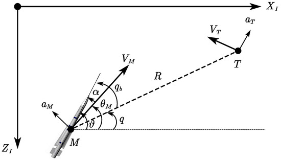
Figure 1.
Longitudinal missile–target engagement geometry.
The aerodynamic lift force Y and moment are approximated as follows:
where is the dynamic pressure with the air density , and represents the elevator deflection. The terms S and L are the reference area and reference length, respectively, and represent aerodynamic coefficients, which are set as:
Taking the derivative and combining (1) yield that:
where and represent the accelerations of the hypersonic flight vehicle and the target, respectively. In this paper, the target is assumed to be stationary, which leads to and . Then, (4) can be rewritten as:
Let ; then, according to (5) one has that:
Consider the relationships and , where denotes the pitch angle of the hypersonic flight vehicle. Define that ; then models (1) and (2) can be rewritten as:
where:
where and represent the simplified aerodynamic coefficients, and denote the time-varying unmatched uncertainties, and and denote the time-varying perturbations caused by variations of aerodynamics parameters. In this paper, there are several focuses in the IGC model, which causes the difficulties in designing the IGC law for the strap-down hypersonic vehicles, which are analyzed in detail in the following subsections.
2.2. Field-of-View Constraint
Due to the use of the strap-down seeker in the hypersonic vehicles, there exists the hard limitation in the body line-of-sight (BLOS), which is represented by , which is denoted as the angle between the axis of the body and the line of the vehicle-target. In fact, the FOV constraint is little considered for the flight vehicles with the platform seeker. Since the platform has a gimbal structure, it can provide a wide FOV range. However, for the hypersonic vehicles equipped with a strap-down seeker, the detective range depends on the FOV. Once the FOV is escaped, the target will be missed and result in mission failure.
For the strap-down hypersonic vehicle, the optical axis of the seeker is connected fixedly with the vehicle’s body, and the BLOS angle should be strictly limited in the range of the seeker’s effective field of view, which can be represented as , where and denote the lower and upper limitations of the BLOS, respectively. During the final phase of the engagement, the BLOS constraint should always be met, and its representation is obtained by the following relationship:
In this paper, to simplify the researched issue, the FOV constraint is set as a symmetric form, which can be expressed as:
where is a positive constant.
Define that ; then, we have that , where . Thus, the IGC model is updated as the following expression:
2.3. Issues of Unmatched Uncertianties and Partial Measurement
As demonstrated in model (11), the IGC model for strap-down hypersonic vehicles is obtained, which exhibits the following two features.
As seen in (11), the IGC model is formulated as a model with the unmatched uncertainties . The uncertainties do not occur in the control channel and thus cannot be dealt with using the traditional control methods. These unmatched uncertainties will cause steady-state errors in the tracking control and even result in the instability and large miss distance of the whole guidance and control system.
On the other hand, the model information may be not completely known. Generally, the state information is obtained through the measurement by the sensors. However, for several types of flight vehicles, some state measurements may be not available. Thus, differently from the general hypersonic vehicles, the output of the whole IGC model is set as , and the controller should be designed under the output measurement.
2.4. Control Objective
In this paper, the control goal of the integrated guidance and control system is to design an IGC law to ensure the success of the interception under the partial measurement and unmatched uncertainties . Moreover, the FOV constraint is always guaranteed in the overall flight envelope.
3. Output-Based Finite-Time Disturbance Observer
The important task for addressing the control goal is to deal with the unmatched uncertainties issue by using the partial measurement information. The disturbance observer is a type of estimator used to obtain the disturbance observation, which is capable of solving the problem of the unmatched uncertainties. However, the existing disturbance observers usually estimate the uncertainties using the complete state information, and it is difficult for them to obtain the unmatched uncertainties only by virtue of the output. Therefore, in this part, we first propose a novel output-based finite-time disturbance observer (OFTDO), which not only estimates the unmatched uncertainties precisely, but also can achieve the finite-time convergence of the estimate errors.
Consider an uncertain system:
where denote the state, input and output, respectively, and is the lump disturbance. Matrices have proper dimensions. First of all, some necessary assumptions are listed bellow.
Assumption 1.
Assumption 2.
The matrix has a column full rank.
Assumption 3.
The disturbance and its derivatives up to order r are bounded, where r is a known constant greater than zero.
Remark 1.
The strongly observability in Assumption 1 means that implies that on every nondegenerate interval and for every piecewise continuous (or integrable) function (control) on . It is a necessary condition to construct the state and uncertainties estimates in this paper. More details can be found in [29].
Note that the standard DOs require the complete knowledge of the states when the unmatched uncertainties exist, and thus they are not suitable for the IGC system in this paper where the partial measurement and unmatched uncertainties are considered. Therefore, in the following part a novel OFTDO is presented to estimate the disturbance precisely via the system output.
Theorem 1.
For System (12), if Assumptions 1–3 are satisfied, and the proposed OFTDO is designed as:
where is the differentiator order, and the gain can be obtained as in [30]. The matrix is selected such that is Hurwitz. The function for a vector and a constant . The vector where . Herein, and represent the ith anti-differentiator of , i.e., . The matrices and are constructed in the proof. The parameter is the Lipschitz constant of . Then, the estimation and will converge to the actual values in finite time.
Proof.
The proof is shown in the following three steps.
(1) Define that and one has . Therefore, the following error dynamics are obtained:
where the matrix is Hurwitz.
(2) Let and . Herein, the symbol ⊥ is defined as follows. For a matrix with , the matrix with is defined such that .
The matrix can be defined in a recursive way as follows:
If the system is strongly observable, there exits a unique positive integer such that the matrix satisfies the relationship [31,32]. Therefore, the following expression can be obtained:
where represents the ith anti-differentiator of , i.e., . Note that , and thus, we can obtain that .
(3) Using the high-order sliding mode (HOSM) differentiator
to estimate the vector , the variable can be obtained. It is proven that with the proper choice of the constants , the equality is satisfied after a finite time [30]. Hence, we have that , and holds after a certain time. Moreover, for the error dynamics (14), we have , and thus
can be obtained. The proof is completed. □
The schematic diagram of the proposed OFTDO algorithm is provided in Figure 2. As shown in Figure 2, the presented estimation approach achieves a finite-time observation for the unmatched by introducing a sliding mode technique when only partial information can be measurable.
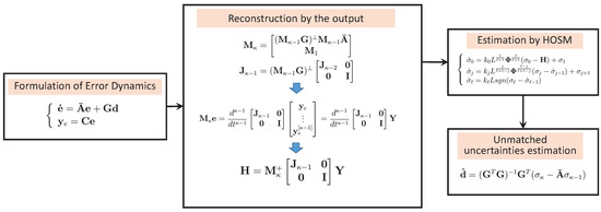
Figure 2.
Schematic diagram of the proposed OFTDO.
Remark 2.
The high-order sliding mode differentiator differentiates a continuous signal and obtain its derivative up to r. Assumption 3 is necessary for the introduction of the HOSM technique. Moreover, the HOSM method is capable of ensuring the continuousness of the control signal since the sign function is hidden in the integral part, rather than introducing the discontinuous term in the control in the standard sliding mode control.
4. Constrained IGC Scheme Design
As shown in the context above, the predefined requirement on the BLOS constraint is , and the designed constrained IGC scheme should ensure that the state converges to the origin and the BLOS is always inside the prescribed limitations. First, some necessary lemmas are given to facilitate the control design and stability analysis.
4.1. Preminaries
Lemma 1
([15]). For any positive constants , let and are an open set. Consider the system:
where , is piecewise continuous in t, and locally Lipschitz in h, uniformly in t, on . Suppose that there exist positive definite functions and , both of which are continuously differentiable in their respective domains, such that as or . Let , and , if the inequality
holds in the set , then for all .
Lemma 2
([16]). For any positive constant A, the following inequality holds for all z in the interval :
where p is a positive constant.
Lemma 3
([19]). For any and , the following inequality always holds:
Remark 3.
Lemma 1 provides the fundamental theory for guaranteeing the stability of the system with a state constraint. In other words, the constraint issue has been solved through the establishment of the proper Lyapunov function. Lemma 2 gives an important inequality for the stability analysis.
4.2. OFTDO Design
For the application in the IGC system (11), the following assumption is given for the design of the OFTDO.
Assumption 4.
The lump uncertainties their its first and second derivatives are bounded.
Remark 4.
Note that only the aerodynamic perturbations are considered, and thus the wind gusts are not involved in the paper. In (8), the unmatched uncertainties are functions of the states, and thus and their first- and second-order derivatives can be considered to be bounded in the flight. Therefore, Assumption 4 is reasonable.
First, it can be checked and confirmed that Assumptions 1 and 2 are satisfied. For the IGC model (11), it can be obtained that , , and . The disturbance is reconstructed by to adapt the use of Theorem 1. Then, it can be verified that the system is strongly observable according to [29].
Then, following (15), it can be calculated that , thus . If the matrix is set as , thus . Then, it follows that
which is a column full rank, and thus .
According to Assumption 4, it can be found that Assumption 3 means that , and thus we have that . Therefore, the following HOSM differentiator:
is used to estimate the variable , where the output error . Then, the estimate of is obtained by . Note that the sign function will cause some unnecessary oscillation in the control input, and thus we instead use the saturation function to replace it in the simulation.
4.3. Constrained IGC Law Design
In the procedure of IGC law design, the backstepping technique is used. We define the tracking error as where denotes the desired reference. In this paper, the reference is set as . Then, one has that:
We introduce the virtual control , which is designed as:
where the term is the estimation from the proposed OFTDO and is a positive constant. Then, substituting (26) into (25) yields:
where represents the estimation of the uncertainties.
To avoid the “explosion of terms” problem, the dynamic surface technique is applied, and the following filter is presented in this paper:
where are positive constants. The hyperbolic tangent function term is a typical nonlinear function that is capable of accelerating the convergence when the filter errors are far away from zero and avoiding the chattering around zero. Consequently, the performance of the filter can be effectively improved compared with the standard first-order filter.
Next, we define the error variable as , and the derivative of is obtained by:
Then, we introduce the virtual control as the following form:
where denotes the estimation error of the uncertainties , and is a positive constant. Similarly, the filter is used as , where are positive constants.
Next, we define the error variable as , and the virtual control is designed as:
Similarly, the filter is used as , where are positive constants.
Finally, the controller is obtained by:
where the error variable is defined as , where is estimated by the OFTDO. The term denotes the estimation error of the uncertainties by the proposed OFTDO, and is a positive constant.
4.4. Stability Analysis
This part provides the stability analysis of the closed-loop system under the proposed IGC law (32).
Define that:
where denotes the estimation error of the state , and represents the estimation error of the disturbance and the filter error.
A Lyapunov function candidate is selected as:
where log denotes the natural logarithm. Note that and taking the derivative of yields:
Combining (31) and taking the derivative of yields that:
Calculating the derivative of and substituting the controller (32), one has that:
We choose a new Lyapunov function as:
Note that:
and taking the derivative of V yields:
Reorganizing the derivative of V yields that:
Utilizing Young’s inequality, the following relationships are satisfied:
and substituting (43)–(47) into (42) yields:
According to Lemma 3, one has that:
where . Note that the estimation of the states and uncertainties are achieved in finite time, and thus and hold after a finite time moment . Assume that the term is also bounded; then we have , in which is a positive constant. Therefore, one has:
where . Then, the following theorem is obtained.
Theorem 2.
Consider the IGC system (11). If the controller is designed as (26), (30), (31) and (32), the initial value satisfies , and are chosen such as , then the system will have the following properties:
(a) The tracking errors of the system state are ultimately bounded.
(b) The constraint requirement will not be violated.
Proof.
Integrating (50), we obtain:
therefore, the function V is bounded, which implies that all of the states of the closed-loop system are bounded, and the tracking errors are ultimately bounded.
Moreover, from (39) and (50), we can conclude that holds if the initial value satisfies according to Lemma 1. Therefore, the constraint requirement is not violated during the dynamic process. The proof is completed.
Remark 5.
It is worth noting that the estimation errors and will converge to zero in finite time by the proposed OFTDO. Therefore, the convergence boundary is only related to the terms , and . If is selected to be large enough, we have . If the command is chosen to be small, the final convergence domain will be decreased.
The schematic diagram of the proposed control scheme is provided in Figure 3. As shown in Figure 3, the presented approach achieves a control framework that covers the FOV requirement, partial measurement and unmatched uncertainties.
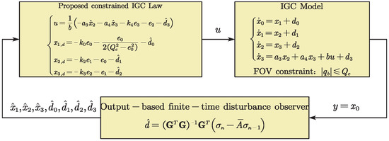
Figure 3.
Schematic diagram of the proposed control.
5. Simulation and Discussion
5.1. Simulation Settings
The initial conditions were set as km and km, and the location of the target was set as km and . The initial angles of the hypersonic flight vehicle were , . The missile and the target were set to fly with constant velocities of 6 Ma and 0 m/s, respectively. The aerodynamic coefficients were set as:
The control input was restricted as . The FOV constraint was set as . Parameters of the proposed control method were chosen as .
5.2. Results and Discussions
The simulation results are shown in Figure 4, Figure 5, Figure 6, Figure 7, Figure 8, Figure 9 and Figure 10 and the estimations of the disturbances are shown in Figure 11, Figure 12 and Figure 13. As seen in Figure 4 and Figure 5, the final miss of distance is small, which means that the fine engagement has been achieved by the proposed IGC law in (32). Moreover, the BLOS angle is constrained in the prescribed FOV limitations, which shows that the FOV constraint is not violated in the flight procedure. The angle of attack , pitch rate and evaluator are shown in Figure 8, Figure 9 and Figure 10. Meanwhile, the estimation of the uncertainties in Figure 11, Figure 12 and Figure 13 demonstrates that the proposed OFTDO has achieved the finite-time estimation of the unknown unmatched uncertainties successfully.
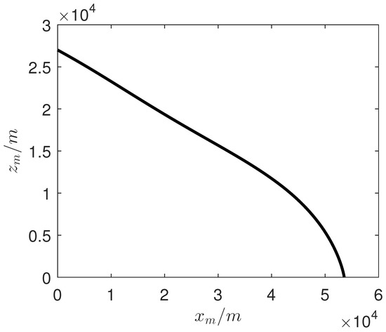
Figure 4.
Curve of trajectory on the x and z axes.
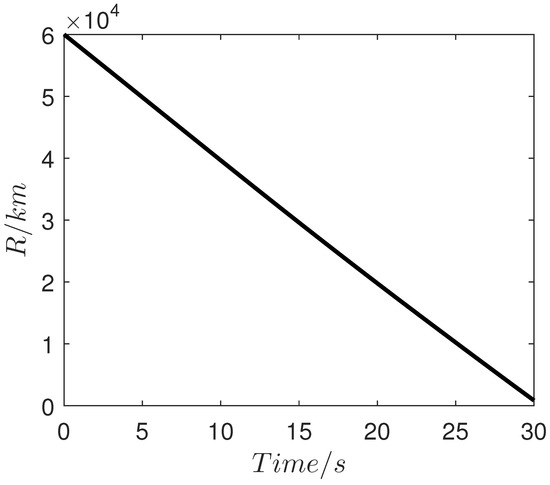
Figure 5.
Curve of the relative distance R.
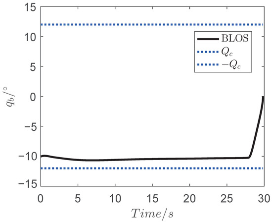
Figure 6.
Curve of body line-of-sight angle .
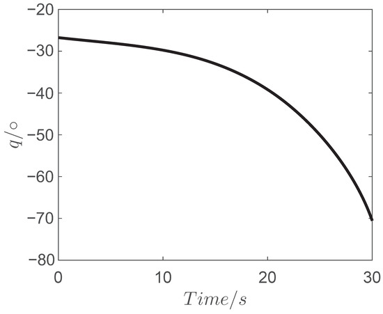
Figure 7.
Curve of line-of-sight angle q.
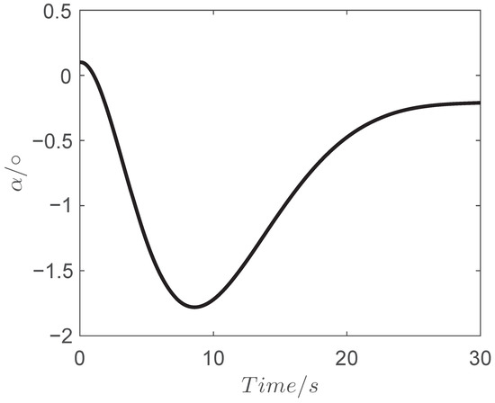
Figure 8.
Curve of the angle of attack .
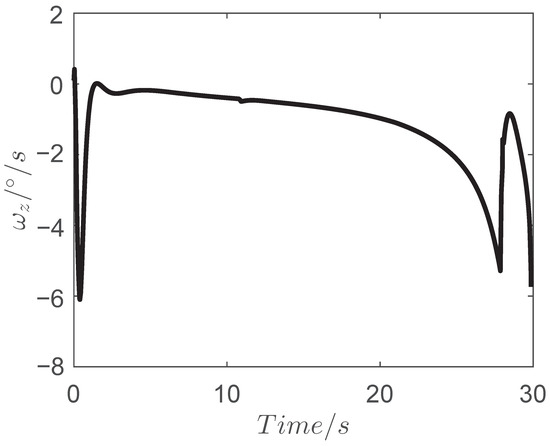
Figure 9.
Curve of the pitch rate .
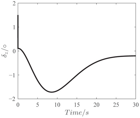
Figure 10.
Curve of the elevator .
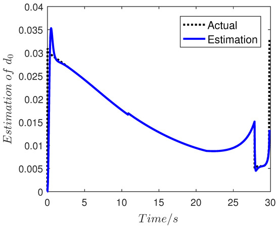
Figure 11.
Curve of the estimation .
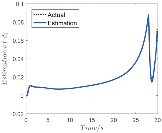
Figure 12.
Curve of the estimation .
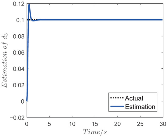
Figure 13.
Curve of the estimation .
To further test the robustness and effectiveness of the proposed IGC law, Monte-Carlo tests were carried out in the simulation. The number of the tests was set as 500 times, and the final location on the x and z axes and the missed distance are shown in Figure 14 and Figure 15, respectively. The mean and the standard deviation can be calculated as 0.501 m and 0.7741 m, respectively. As seen in these figures, the distribution of the missed distance is smaller than 1 m, which shows the strong robustness of the proposed IGC law.
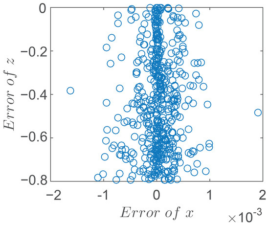
Figure 14.
Curve of Monte-Carlo results on the x and z axes.
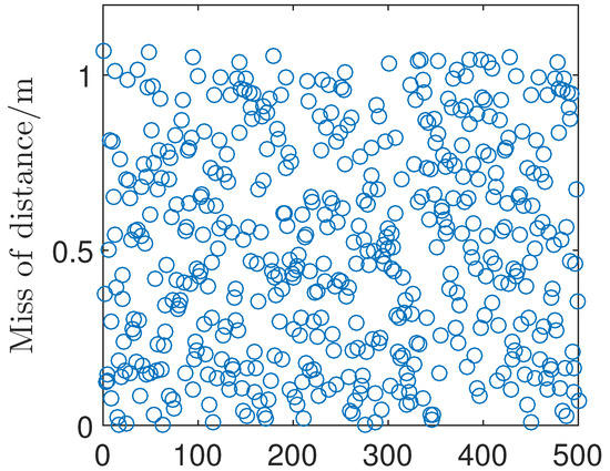
Figure 15.
Curve of the missed distance in the Monte-Carlo tests.
6. Conclusions
An integrated guidance and control law for strap-down hypersonic flight vehicles was proposed, with partial measurement information and unmatched uncertainties. A constrained IGC scheme was proposed by combining the barrier Lyapunov function-based backstepping methodology and the specific output-based finite-time disturbance observer. The effectiveness of the presented scheme was verified by numerical simulations and Monte-Carlo tests. Future researches include the the constrained performance optimization, and consideration of the actuator dynamics and wind gust disturbance.
Author Contributions
Methodology, M.D.; software, X.X. and F.X.; writing—original draft preparation, M.D.; writing—review and editing, M.D. All authors have read and agreed to the published version of the manuscript.
Funding
This research received no external funding.
Institutional Review Board Statement
Not applicable.
Informed Consent Statement
Not applicable.
Data Availability Statement
Not applicable.
Conflicts of Interest
The authors declare no conflict of interest.
References
- Bolender, M.A. An overview on dynamics and controls modelling of hypersonic vehicles. In Proceedings of the 2009 American Control Conference, St. Louis, MO, USA, 10–12 June 2009; pp. 2507–2512. [Google Scholar]
- Fiorentini, L.; Serrani, A. Adaptive restricted trajectory tracking for a non-minimum phase hypersonic vehicle model. Automatica 2012, 48, 1248–1261. [Google Scholar] [CrossRef]
- Lv, M.; Schutter, B.; Baldi, S. Non-Recursive Control for Formation-Containment of HFV Swarms with Dynamic Event-Triggered Communication. IEEE Trans. Ind. Informat. 2022. [CrossRef]
- Sagliano, M.; Mooij, E.; Theil, S. Adaptive disturbance-based high-order sliding-mode control for hypersonic-entry vehicle. J. Guid. Control Dyn. 2017, 40, 521–536. [Google Scholar] [CrossRef]
- Guo, Z.Y.; Guo, J.G.; Zhou, J.; Chang, J. Robust tracking for hypersonic reentry vehicles via disturbance estimation-triggered control. IEEE Trans. Aerosp. Electron. Syst. 2019, 56, 1279–1289. [Google Scholar] [CrossRef]
- Zong, Q.; Ji, Y.; Zeng, F.; Liu, H. Output feedback back-stepping control for a generic hypersonic vehicle via small-gain theorem. Aerosp. Sci. Technol. 2012, 23, 409–417. [Google Scholar] [CrossRef]
- Hu, G.J.; Guo, J.G.; Guo, Z.Y.; Cieslak, J.; Henry, D. ADP-based intelligent tracking algorithm for reentry vehicles subjected to model and state uncertainties. IEEE Trans. Ind. Informat. 2022. [Google Scholar] [CrossRef]
- Xiong, Z.; Peng, H.; Wang, J.; Wang, R.; Liu, J.Y. Dynamic calibration method for SINS lever-arm effect for HCVs. IEEE Trans. Aerosp. Electron. Syst. 2015, 51, 2760–2771. [Google Scholar] [CrossRef]
- Chen, K.; Zhou, J.; Shen, F.Q.; Sun, H.Y.; Fan, H. Hypersonic boost-glide vehicle strap-down inertial navigation system/global positioning system algorithm in a launch-centered earth-fixed frame. Aerosp. Sci. Technol. 2020, 98, 105679. [Google Scholar] [CrossRef]
- Wang, J.H.; Liu, L.H.; Zhao, T.; Tang, G.J. Integrated guidance and control for hypersonic vehicles in dive phase with multiple constraints. Aerosp. Sci. Technol. 2016, 53, 103–116. [Google Scholar] [CrossRef]
- Koren, A.; Idan, M.; Golan, O.M. Integrated sliding mode guidance and control for a missile with on–off actuators. J. Guid. Control Dyn. 2008, 31, 204–214. [Google Scholar] [CrossRef]
- Guo, J.G.; Xiong, Y.; Zhou, J. A new sliding mode control design for integrated missile guidance and control system. Aerosp. Sci. Technol. 2018, 78, 54–61. [Google Scholar] [CrossRef]
- Panchal, B.; Mate, N.; Talole, S.E. Continuous-time predictive control-based integrated guidance and control. J. Guid. Control Dyn. 2017, 40, 1579–1595. [Google Scholar] [CrossRef]
- Santoso, F.; Garratt, M.A.; Anavatti, S.G. State-of-the-art integrated guidance and control systems in unmanned vehicles: A Review. IEEE Syst. J. 2021, 15, 3312–3323. [Google Scholar] [CrossRef]
- Tee, K.P.; Ge, S.S.; Tay, E.H. Barrier Lyapunov functions for the control of output-constrained nonlinear systems. Automatica 2009, 45, 918–927. [Google Scholar] [CrossRef]
- Ren, B.; Ge, S.S.; Tee, K.P.; Lee, T.H. Adaptive neural control for output feedback nonlinear systems using a barrier Lyapunov function. IEEE Trans. Neural Netw. 2010, 21, 1339–1345. [Google Scholar]
- Lv, M.; Chen, Z.; Schutter, B.; Baldi, S. Prescribed-performance tracking for high-power nonlinear dynamics with time-varying unknown control coefficients. Automatica 2022, 146, 110584. [Google Scholar] [CrossRef]
- Guo, Z.; Henty, D.; Guo, J.; Wang, Z.; Cieslak, J.; Chang, J. Control for systems with prescribed performance guarantees: An alternative interval theory-based approach. Automatica 2022, 146, 110642. [Google Scholar] [CrossRef]
- Li, P.; Yang, G.H. Fault-tolerant control of uncertain nonlinear systems with nonlinearly parameterized fuzzy systems. In Proceedings of the 2009 IEEE Control Applications, (CCA) & Intelligent Control, (ISIC), St. Petersburg, Russia, 8–10 July 2009; pp. 382–387. [Google Scholar]
- Flores, G.; Oca, A.; Flores, A. Robust Nonlinear Control for the Fully Actuated Hexa-Rotor: Theory and Experiments. IEEE Control Syst. Lett. 2023, 7, 277–282. [Google Scholar] [CrossRef]
- Guan, Z.; Liu, H.; Zheng, Z.; Ma, Y.; Zhu, T. Moving path following with integrated direct lift control for carrier landing. Aerospace Sci. Technol. 2022, 120, 107247. [Google Scholar] [CrossRef]
- Ohishi, K.; Nakao, M.; Ohnishi, K.; Miyachi, K. Microprocessor-controlled dc motor for load-insensitive position servo system. IEEE Trans. Ind. Electron. 1987, IE-34, 44–49. [Google Scholar] [CrossRef]
- Chen, W.H.; Ohnishi, K.; Guo, L. Advances in disturbance/uncertainty estimation and attenuation. IEEE Trans. Ind. Electron. 2015, 62, 5758–5762. [Google Scholar] [CrossRef]
- Han, J. Extended state observer for a class of uncertain plants (in Chinese). Control Decis. 1995, 10, 85–88. [Google Scholar]
- Chen, W.H.; Yang, J.; Guo, L.; Li, S.H. Disturbance-observer-based control and related methods—An overview. IEEE Trans. Ind. Electron. 2016, 63, 1083–1095. [Google Scholar] [CrossRef]
- Wang, P.; Zhang, X.B.; Zhu, J.H. Integrated Missile Guidance and Control: A Novel Explicit Reference Governor Using a Disturbance Observer. IEEE Trans. Ind. Electron. 2019, 66, 5487–5496. [Google Scholar] [CrossRef]
- Dong, W.J.; Farrell, J.A.; Polycarpou, M.M.; Djapic, V.; Sharma, V. Command filtered adaptive backstepping. IEEE Trans. Control Syst. Technol. 2012, 20, 566–580. [Google Scholar] [CrossRef]
- Yang, J.; Li, S.; Sun, C.; Guo, L. Nonlinear disturbance observer based robust flight control for airbreathing hypersonic vehicles. IEEE Trans. Aerosp. Electron. Syst. 2013, 49, 1263–1275. [Google Scholar] [CrossRef]
- Kratz, W. Characterization of strong observability and construction of an observer. Linear Algebra Its Appl. 1995, 221, 31–40. [Google Scholar] [CrossRef]
- Levant, A. Higher-order sliding modes, differentiation and output-feedback control. Int. J. Control 2003, 76, 924–941. [Google Scholar] [CrossRef]
- Ferreira, A.; Cieslak, J.; Henry, D.; Zolghadri, A.; Fridman, L. Output tracking of systems subjected to perturbations and a class of actuator faults based on HOSM observation and identification. Automatica 2015, 59, 200–205. [Google Scholar] [CrossRef]
- Ferreira, A.; Bejarano, F.; Fridman, L. Robust Control With Exact Uncertainties Compensation: With or Without Chattering? IEEE Trans. Control Syst. Technol. 2011, 19, 969–975. [Google Scholar] [CrossRef]
Publisher’s Note: MDPI stays neutral with regard to jurisdictional claims in published maps and institutional affiliations. |
© 2022 by the authors. Licensee MDPI, Basel, Switzerland. This article is an open access article distributed under the terms and conditions of the Creative Commons Attribution (CC BY) license (https://creativecommons.org/licenses/by/4.0/).