Article

Effect of Installation Error on Rotary Seal of Aero Engine

Ministry of Chemical Safety Education Engineering Research Centre, Beijing University of Chemical Technology, Beijing 100029, China
*
Authors to whom correspondence should be addressed.
Aerospace 2022, 9(12), 820; https://doi.org/10.3390/aerospace9120820
Submission received: 10 November 2022 / Revised: 9 December 2022 / Accepted: 12 December 2022 / Published: 14 December 2022

Abstract

:
The rotary seal is a key component of the aero engine. Under actual working conditions, most rotary seals always operate in an eccentric state (caused by installation errors), and when a large eccentricity occurs, it may lead to a large amount of gas leakage, resulting in a decrease in aero engine efficiency, which ultimately affects the reliability and life of the aero engine. Therefore, the effect of installation error on the rotary seal of the aero engine was studied in this research. The flow field numerical models of the honeycomb seal, labyrinth seal, and hybrid labyrinth–honeycomb seal were established, the effects of the honeycomb seal, labyrinth seal, and hybrid labyrinth–honeycomb seal on leakage were numerically analyzed, the sealing mechanisms of three types of seals were revealed, and the effect of radial eccentricity on the leakage of three types of seals was also studied. Additionally, the high-pressure and high-speed rotary seal experiment bench was improved, the effect of eccentricity on the leakage characteristics of the honeycomb seal, labyrinth seal, and hybrid labyrinth–honeycomb seal was studied using the improved experiment bench, and the leakage characteristics of the three types of seals were compared under the same condition. The experimental results are consistent with the numerical simulation results; the honeycomb seal is the least sensitive to eccentricity, and its sealing performance is the best. The research results in this paper reveal the seal mechanisms of the honeycomb seal, labyrinth seal, and hybrid labyrinth–honeycomb seal and demonstrate the effect law of eccentricity regarding the leakage characteristics of these three types of seals. The results of this research can provide theoretical support for aero engine efficiency improvement.

1. Introduction

The rotary seal is a key component of the aero engine, which has important roles in leakage prevention and energy saving. It is widely used in aviation, aerospace, chemical, ships, vehicles, and other fields [1,2,3,4,5]. At present, the most commonly used seals are labyrinth seals, honeycomb seals, and hybrid labyrinth–honeycomb seals [6,7,8]. Under actual working conditions, most rotary seals always operate in an eccentric state (caused by installation errors) [9]. When a large eccentricity occurs, it may lead to a large amount of gas leakage, resulting in reduced aero engine efficiency and ultimately affecting the reliability and life of the aero engine.
Many research institutions and scholars have studied labyrinth seals, honeycomb seals, and hybrid labyrinth–honeycomb seals. Kamouni [10] predicted the leakage flow rate and rotor dynamics coefficient of the eccentric labyrinth seal with four teeth fixed on the rotor based on the CFD calculation model. Pugachev et al. [11] studied the CFD model for predicting labyrinth seal leakage and the rotor dynamic coefficient. Untaroiu et al. [12] studied the effect of several new groove geometries on the dynamic coefficients of the labyrinth seal rotor, and the results showed that the groove shape of the labyrinth seal could be optimized to produce a lower leakage, with only a small change in the dynamic characteristics. Yahyai and Mba [13] carried out a rotor dynamics analysis on the compressor with a labyrinth seal in the interstage seal system. The analysis results showed that the excessive vibration observed at 5447 rpm was caused by friction between the rotor and the seals. Teran et al. [14] analyzed the failure of hydroelectric generators, the main symptom of failure was the increased temperature of the bearings caused by an increase of almost two bars in the pressure between the cover on the side of the generator and the runner, which was caused by the wearing of the seal labyrinths. Li et al. [15] introduced the experimental and computational research of radial flow into the shield gap in turbines with labyrinth seals. Compared with the results without leakage, the numerical calculation results, including the leakage of the labyrinth seal, were in good agreement with the experimental results, indicating that the leakage of the labyrinth seal could not be ignored. Jia et al. [16] proposed a new type of seal called the T-labyrinth seal to reduce the vibration force caused by the flow in the seal area so as to reduce the rotor vibration in the aero engine. With the same seal axial length and tip clearance, the leakage of the T-seal is approximately 23.6–25.3% less than that of a straight-through labyrinth seal and approximately 7.4–8.5% more than that of a staggered labyrinth seal. Flouros et al. [17] studied the effects of design parameters such as seal clearance, thread size, and scallop width on seal leakage characteristics under different operating conditions. Kong et al. [18] built an experiment bench and manufactured labyrinth rings with different rotor tip radii to study the influence of tip clearance and measured oral leakage flow, wind-resistance heating, and eddy current ratio at different speeds and different labyrinth rings. In order to reduce gas leakage, Zhao et al. [19] optimized the shape of the labyrinth seal and used a chaotic optimization algorithm to determine the optimal design parameters of the labyrinth seal. The results show that when the seal clearance, fin width, fin height, fin spacing, and fin front and rear expansion angles are 0.2 mm, 0.1 mm, 7 mm, 9 mm, 0°, and 15°, respectively, the flow coefficient reaches a minimum in the design space. Yang et al. [20] established a numerical analysis model of the hybrid labyrinth–honeycomb seal and studied the static stability and leakage characteristics of the seal under blocked and non-blocked flow states and different eccentricities. Childs et al. [21] tested the leakage and rotor dynamic characteristics of the seal. The test results show that the honeycomb seal has the best sealing performance, followed by the labyrinth seal and the smooth seal. Soulas and Andres [22] used the proposed model to study the influence of rotor eccentricity on the static and dynamic forced responses of the smooth ring seal and the honeycomb seal, and the results showed that the leakage of the two types of seals increased slightly with the increase in rotor eccentricity. Gao et al. [23] studied the effects of honeycomb unit size, axial length, and inlet pre-swirl on sealing performance. The results show that with the increase in wick depth, the leakage of honeycomb seals increases initially due to the increase in airflow velocity and then decreases due to the strong dissipation effect of turbulence. With the increase in the relative edge distance of the core and the decrease in the axial length, the decrease in the number of honeycomb cores on the stator surface weakens the dissipation capacity of turbulence, resulting in an increase in leakage. Import pre-rotation has little effect on leakage. Liu et al. [24] studied the influence of the blocking rate of honeycomb seal cells on leakage characteristics and verified it through experiments. Li et al. [25,26,27] studied a series of factors, including sealing clearance, cell diameter, cell depth, rotational speed, and pressure ratio, to determine how these factors affect the leakage flow rate of labyrinth honeycomb seals. The results show that the labyrinth honeycomb seal has the best sealing performance when the honeycomb unit diameter is equal to the step width of the labyrinth. Under the design conditions, the ratio of honeycomb unit depth to honeycomb unit diameter is 0.93. Through a comprehensive analysis of the current literature, it can be found that most of these studies of the labyrinth seal, honeycomb seal, and hybrid labyrinth–honeycomb seal focus on the seal structure, and some of them are about the eccentricity of the seal leakage characteristics; however, these studies are basically only numerical simulation studies, and few experimental studies on the effect of eccentricity on seal leakage are mentioned. Therefore, the effect of installation error (eccentricity) on seal leakage characteristics is studied in this research. The above research provides theoretical support for the improvement of aero engine efficiency.
In this research, the flow field numerical models of the honeycomb seal, labyrinth seal, and hybrid labyrinth–honeycomb seal were established. Firstly, the flow field characteristics of the three types of seals were analyzed, and the effect of radial eccentricity on the leakage characteristics of the three types of seals was studied. Then, the high-pressure and high-speed rotary seal experiment bench was improved. Finally, the effect of eccentricity on the leakage characteristics of the honeycomb seal, labyrinth seal, and hybrid labyrinth–honeycomb seal was studied by using the improved experiment bench, and the numerical simulation results were verified the experiment results. Through the above research, the research results will provide theoretical support for aero engine efficiency improvement.

2. Theoretical Analysis of Seal Flow Field

2.1. Seal Flow Field Numerical Model

2.1.1. Structure Parameters of Numerical Model

The seals to be studied in this research were honeycomb seals, labyrinth seals, and hybrid labyrinth–honeycomb seals, and the structure parameters of the seals are shown in Figure 1. As shown in Figure 1a, the labyrinth seal was located on the stator, the tooth spacing T is 3.6 mm, the tooth thickness t is 0.5 mm, the seal depth h is 3.2 mm, the number of teeth is seven, the shaft diameter dLS is 55 mm, and the seal radius clearance c is 0.25 mm.
As shown in Figure 1b, the honeycomb seal is located on the stator, the honeycomb cell diameter B is 1.6 mm, the honeycomb cell wall thickness b is 0.1 mm, the seal depth h is 3.2 mm, the number of honeycomb layers is 13, the shaft diameter dHS is 55 mm, and the seal radius clearance c is 0.25 mm.
As shown in Figure 1c, the honeycomb of the hybrid labyrinth–honeycomb seal is located on the stator, and the labyrinth is located on the rotor. The tooth spacing T is 3.6 mm, the tooth thickness t is 0.5 mm, the seal depth h is 3.2 mm, the number of teeth is seven, the shaft diameter dHLHS is 55 mm, the honeycomb cell diameter B is 1.6 mm, the cell wall thickness b is 0.1 mm, the number of honeycomb layers is 13, and the seal radius clearance c is 0.25 mm.
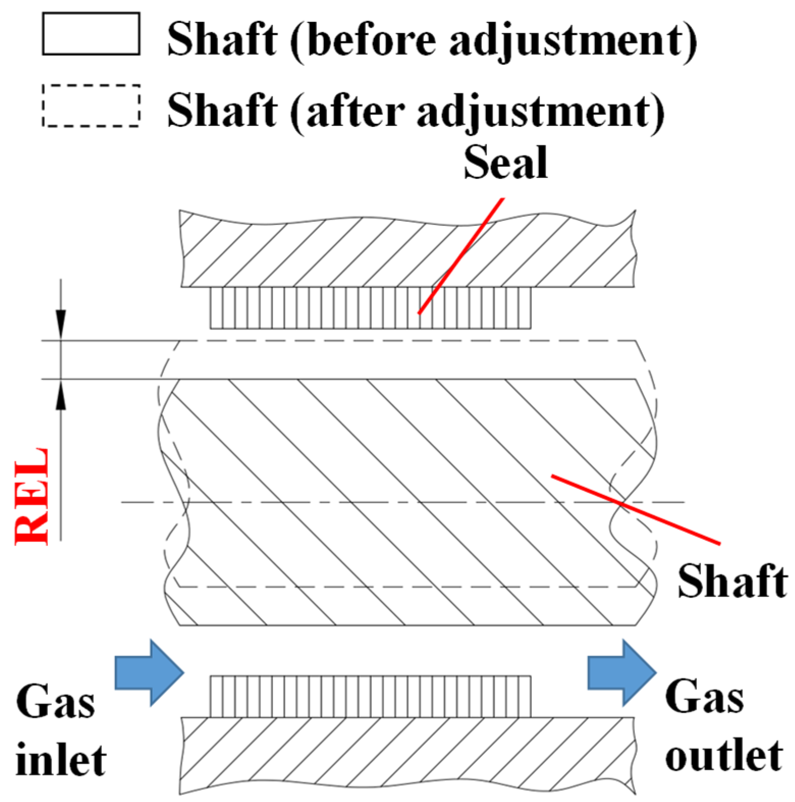
The schematic diagram of the radial eccentricity of the seal is shown in Figure 2. The shaft moves left in the radial direction to produce a radial eccentricity to the left, thereby obtaining a seal under radial eccentricity; the eccentricity at this time is REL. According to the given REL and the relevant structural parameters of the seal, the seal flow field model under radial eccentricity can be constructed.

2.1.2. Mesh Division and Boundary Conditions of Numerical Model

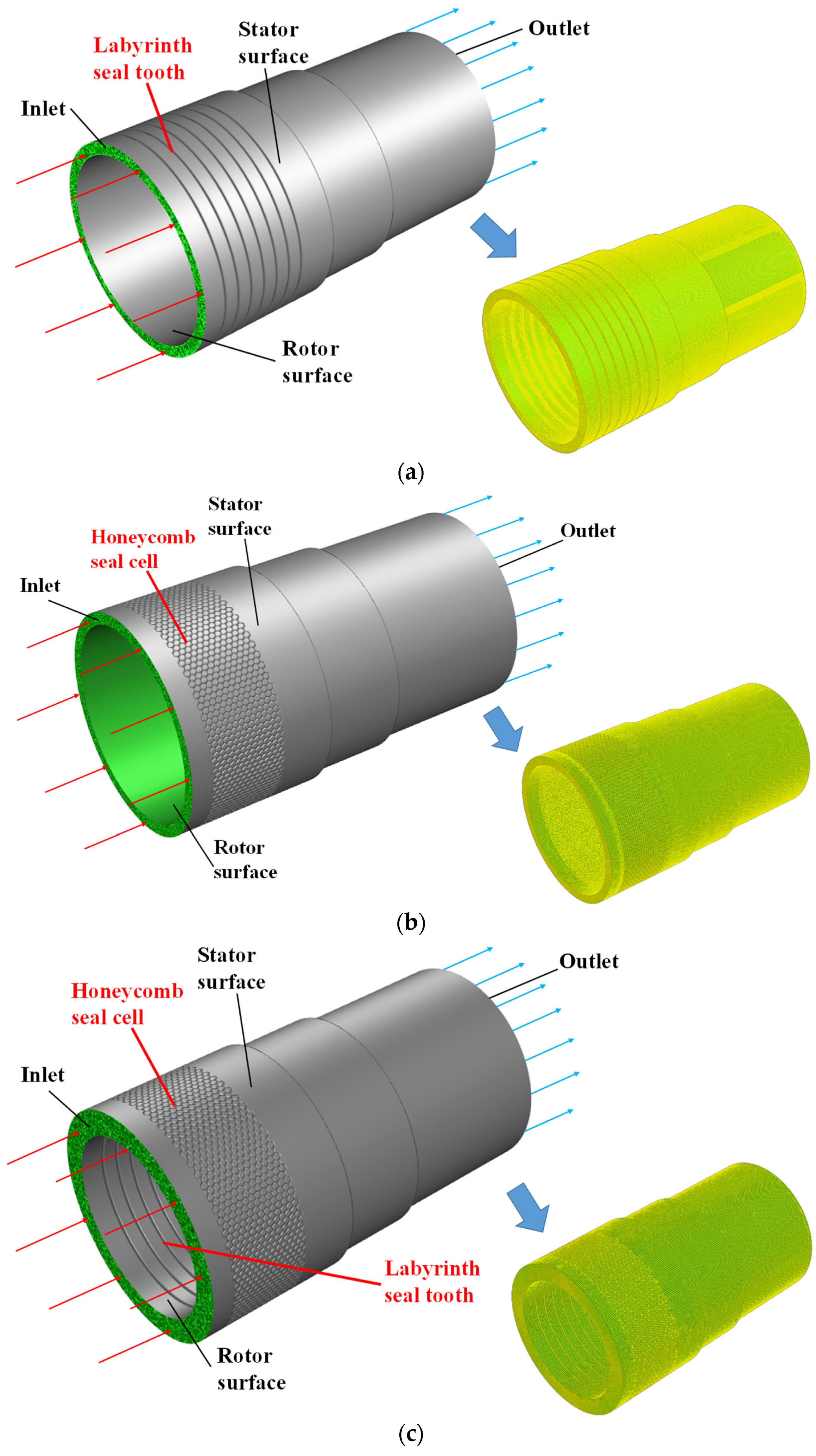
The flow field numerical models of the labyrinth seal, honeycomb seal, and hybrid labyrinth–honeycomb seal were established according to the seal size mentioned above. The flow field numerical models of the labyrinth seal, honeycomb seal, and hybrid labyrinth–honeycomb seal are shown in Figure 3a–c. In this article, the computational domain fluid is an ideal gas, using the k-ε turbulence model and the wall function method. The inlet of the model uses the pressure inlet boundary, and the total temperature and total pressure are given, the inlet pressure range is 2–10 kPa. The outlet uses the pressure outlet boundary, and the atmospheric pressure is given. The rotor surface uses a rotating adiabatic solid wall surface, and the stator surface uses a non-slip adiabatic solid wall surface.
Taking labyrinth seals as an example, the meshing of the model is introduced. The grid division of the labyrinth seal flow field numerical model is shown in Figure 3a. The labyrinth seal flow field numerical model adopts a structural grid. In order to determine the appropriate number of grids, the influence of the number of grids on the sealing leakage was analyzed. The goal is to keep the leakage of the final seal unaffected by the number of grids and the computation time relatively short; that is, the number of grids is the least when the sealing leakage is not affected by the number of grids. When the number of grids is 4.5 million, the relative error of the leakage caused by the number of grids is less than 0.5%. It can be considered that the influence of the number of grids on the leakage has little effect on the calculation results. Therefore, considering the calculation accuracy and research time, the final computational grid number of the flow field numerical model is about 4.5 million.

2.2. Analysis of Seal Flow Field without Eccentricity

2.2.1. Analysis of Seal Leakage Characteristics without Eccentricity

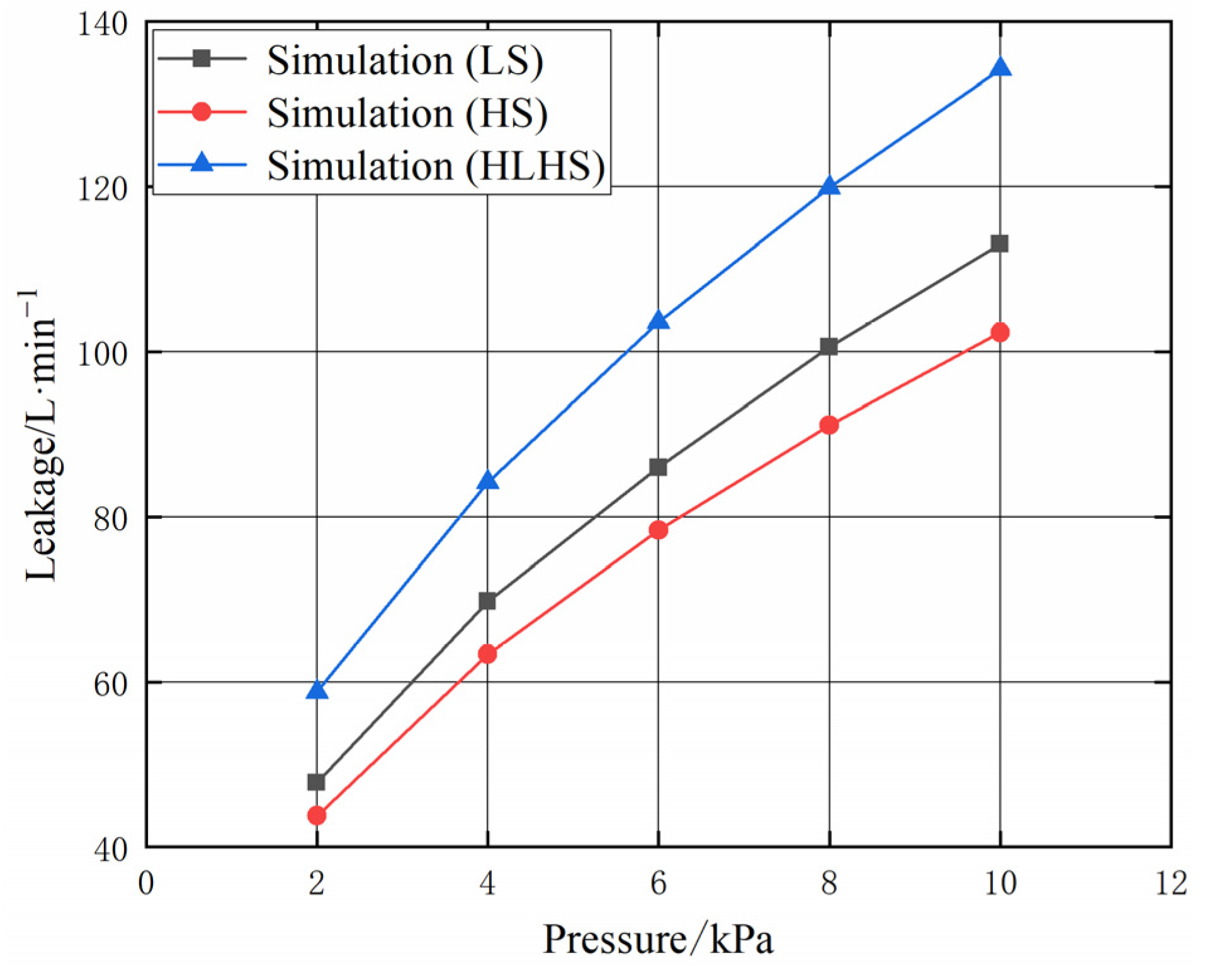
The leakage results of the labyrinth seal, honeycomb seal, and hybrid labyrinth–honeycomb seal without eccentricity are shown in Figure 4; under the same conditions, the leakage of the hybrid labyrinth–honeycomb seal is the largest, the leakage of the labyrinth seal is the second, and the leakage of the honeycomb seal is the smallest. When the radial eccentricity is 0 mm, for every 1 kPa increase in the pressure, the leakage of the labyrinth seal increases by about 8.0 L·min−1, the leakage of the honeycomb seal increases by about 7.3 L·min−1, and the leakage of the hybrid labyrinth–honeycomb seal increases by about 9.4 L·min−1. That is to say, under the same conditions, the leakage growth rate of the hybrid labyrinth–honeycomb seal is the largest, the leakage growth rate of the labyrinth seal is the second, and the leakage growth rate of the honeycomb seal is the smallest. Therefore, the sealing performance of the sealed seal is the best, the sealing performance of the labyrinth seal is the second, and the sealing performance of the hybrid labyrinth–honeycomb seal is the worst.
As can be seen from the previous, the performance of the honeycomb seal is the best, followed by the labyrinth seal, hybrid labyrinth–honeycomb seal is the worst. This is because the airflow will form a small vortex in the annular chamber of the labyrinth seal and dissipate the energy of the gas, while the honeycomb seal divides the annular chamber of the labyrinth seal into many small hexagonal chambers, increasing the vortex that can dissipate energy. Therefore, the performance of the honeycomb seal is better than that of the labyrinth seal, and because the kinetic energy of the gas in the honeycomb seal is converted into more internal energy, its turbulent kinetic energy is relatively smaller. The labyrinth seal teeth on the rotor of the hybrid labyrinth–honeycomb seal are difficult to form a narrow path with the honeycomb seal unit on the stator, which will significantly affect the flow mode in the cavity and clearance of the honeycomb seal and reduce the ability of the seal to dissipate energy. Therefore, the kinetic energy of the gas in the hybrid labyrinth–honeycomb seal is converted into the least internal energy, which makes the turbulent kinetic energy in the hybrid labyrinth–honeycomb seal relatively high, so the performance of the hybrid labyrinth–honeycomb seal is the worst.

2.2.2. Analysis of Seal Flow Field Characteristics without Eccentricity

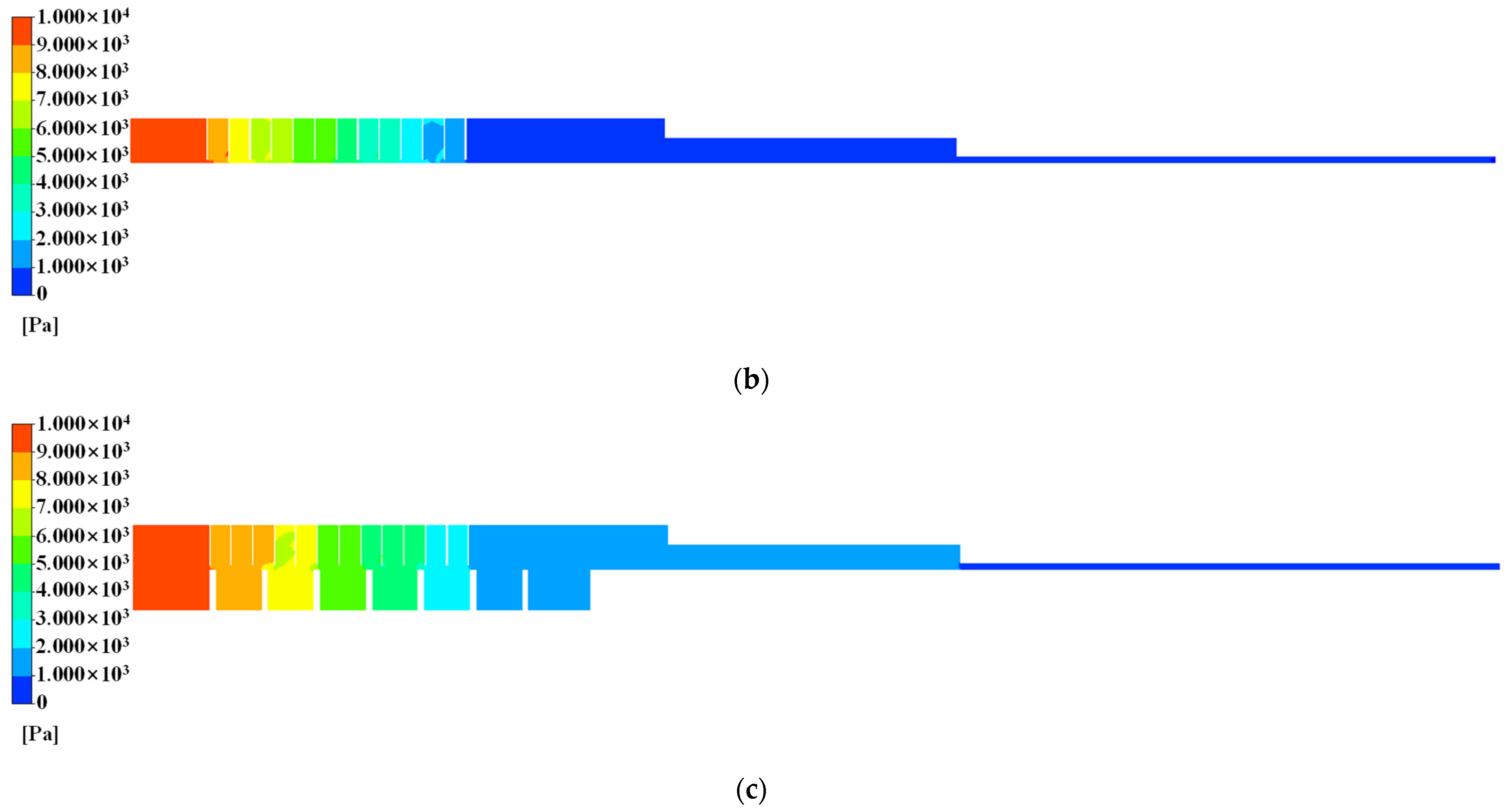
Figure 5 shows the pressure distribution of the labyrinth seal, the honeycomb seal, and the hybrid labyrinth–honeycomb seal. It can be seen from Figure 5 that, compared with the labyrinth seal and hybrid labyrinth–honeycomb seal, the pressure drop of the honeycomb seal is more uniform; that is, the stability of the honeycomb seal is better than the labyrinth seal and hybrid labyrinth–honeycomb seal. The pressure from the seal inlet to the seal outlet decreases step by step, and the pressure in the honeycomb cell and the labyrinth tooth chamber is basically the same, indicating that the pressure drop of the sealing mainly occurs at the seal clearance. The airflow velocity increases at the seal clearance, which converts part of the pressure energy into kinetic energy. However, in the honeycomb cell and the labyrinth tooth chamber, the airflow energy is dissipated by converting it into internal energy, so it has little effect on the pressure, and the pressure change is not obvious. It can also be seen from Figure 5 that the pressure in the four corners of the labyrinth seal is higher in three chambers, while the pressure in the four corners of the honeycomb seal is higher in one chamber. This is because the pressure in the four corners of the chamber increases due to insufficient vortex dissipation in the chamber. The results show that the vortex dissipation is not sufficient in most of the cavities of the labyrinth seal but only in a few cavities of the honeycomb seal. Therefore, the seal performance of the honeycomb seal is better than that of the labyrinth seal.
The fluid flow in the seal mainly includes the following two parts: the high-speed jet flow between the seal and rotor clearance fluid and the vortex in the cavity formed by the honeycomb cell and labyrinth tooth. Under the action of axial pressure difference and rotor rotation, due to the throttling effect, the airflow will form a high-speed jet at the gap between the seal and the rotor, which is close to the rotor and enters the seal clearance at a large speed. The other part of the fluid forms a vortex under the action of the honeycomb cell and labyrinth tooth. The enclosed honeycomb cell and labyrinth tooth cut and separated the airflow into countless small vortices. It is these vortices that convert the kinetic energy of the gas into internal energy and dissipate, reducing the leakage of the seal.
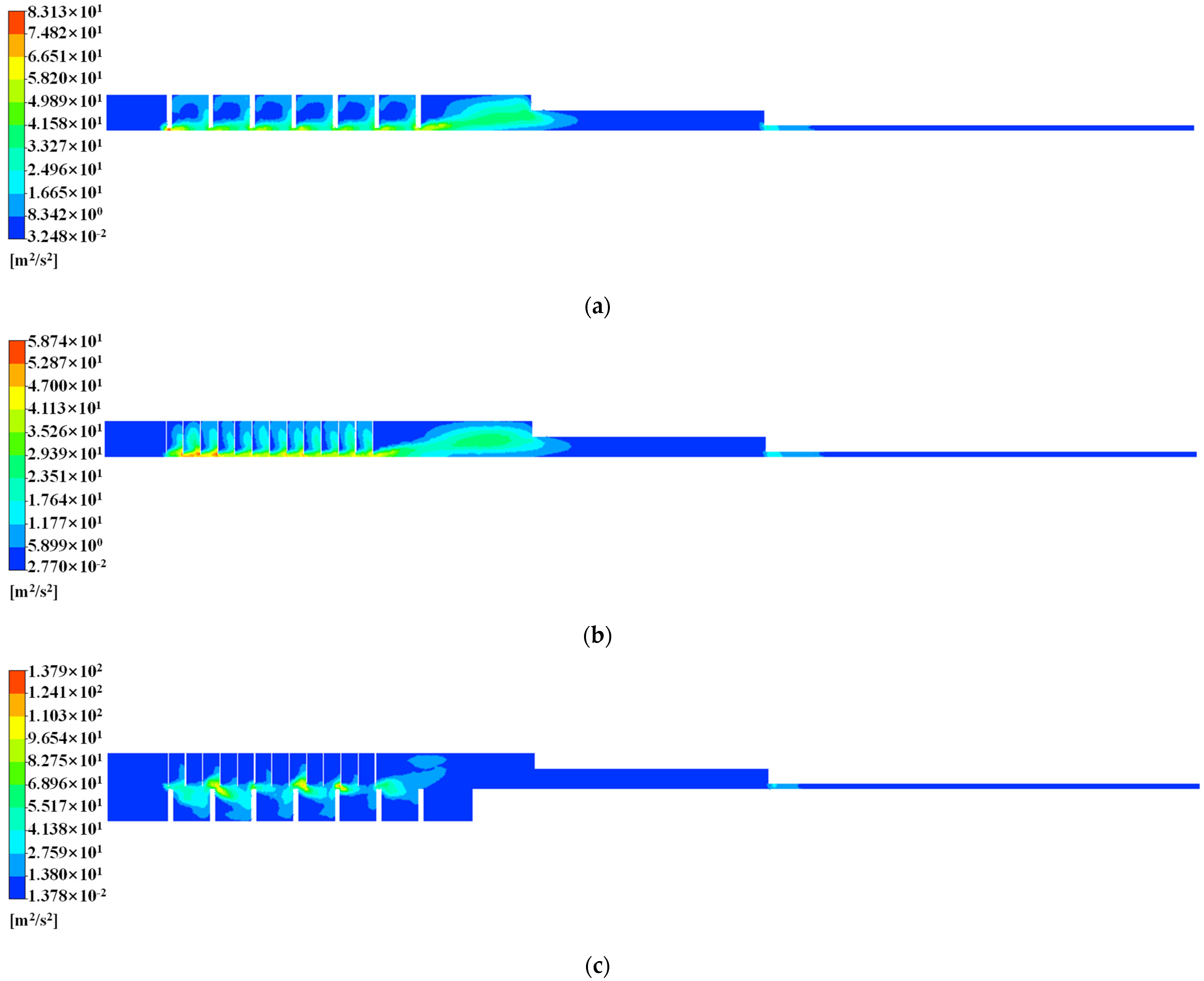
Figure 6 shows the turbulent kinetic energy of the gas in the three types of seals. The maximum turbulent kinetic energy of the gas in the honeycomb seal is 58.74 m2/s2, the maximum turbulent kinetic energy of the gas in the labyrinth seal is 83.13 m2/s2, and the maximum turbulent kinetic energy of the hybrid labyrinth–honeycomb seal is 137.9 m2/s2. Among them, the turbulent kinetic energy of the gas in the honeycomb seal is the smallest, followed by the turbulent kinetic energy of the gas in the labyrinth seal, and the turbulent kinetic energy of the gas in the hybrid labyrinth–honeycomb seal is the largest. This shows that under the same working conditions, the kinetic energy of the gas in the honeycomb seal is converted into the most internal energy and dissipated the most fully. The kinetic energy of the gas in the hybrid labyrinth–honeycomb seal is converted into the least internal energy and dissipates the least energy. Therefore, the seal performance of the honeycomb seal is better than that of the labyrinth seal, and the seal performance of the labyrinth seal is better than that of the hybrid labyrinth–honeycomb seal.

2.3. Analysis of the Effect of Radial Eccentricity on Seal Flow Field

2.3.1. Analysis of Seal Leakage Characteristics under Radial Eccentricity

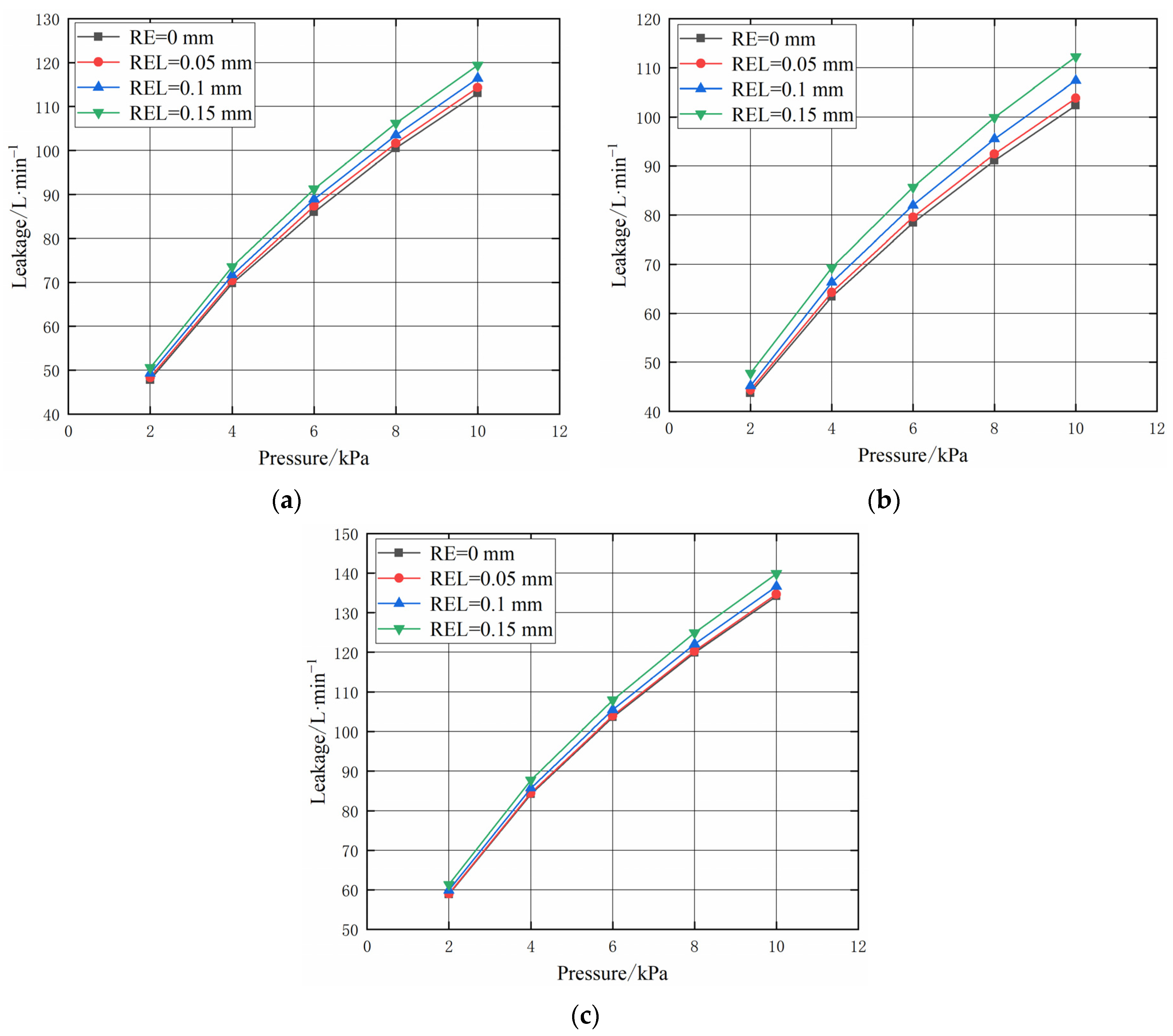
As shown in Figure 7, no matter the labyrinth seal, honeycomb seal, or hybrid labyrinth–honeycomb seal, when the radial installation error (radial eccentricity) is constant, the leakage of the seal is positively related to the radial installation error. When the radial installation error is at its maximum, the leakage of the labyrinth seal increases by about 5.4% compared with that without radial installation error, the leakage of the honeycomb seal increases by about 9.7% compared with that without radial installation error, and the leakage of the hybrid labyrinth–honeycomb seal increases by about 4.2% compared with that without radial installation error. Therefore, when the radial installation errors are the same, the leakage growth rate of the honeycomb seal is the largest, the leakage growth rate of the labyrinth seal is the second, and the leakage growth rate of the hybrid labyrinth–honeycomb seal is the smallest.
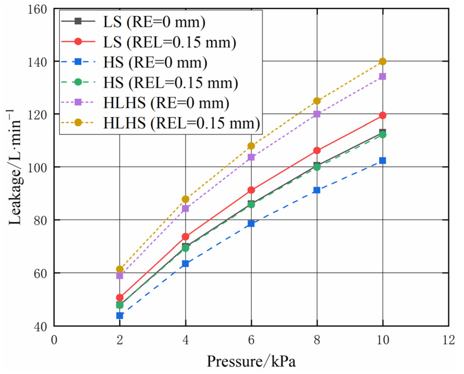
As shown in Figure 8, when the radial installation error (radial eccentricity) of the honeycomb seal is the largest, its leakage is still smaller than that of the labyrinth seal without a radial installation error. When the radial installation error of the labyrinth seal is the largest, its leakage is also smaller than that of the hybrid labyrinth–honeycomb seal without radial installation error; that is, when there is a radial installation error, the leakage relationship among the three types of seals is as follows: the leakage of the hybrid labyrinth–honeycomb seal is the largest, followed by the labyrinth seal, and the honeycomb seal is the smallest.

2.3.2. Analysis of Seal Flow Field Characteristics under Radial Eccentricity

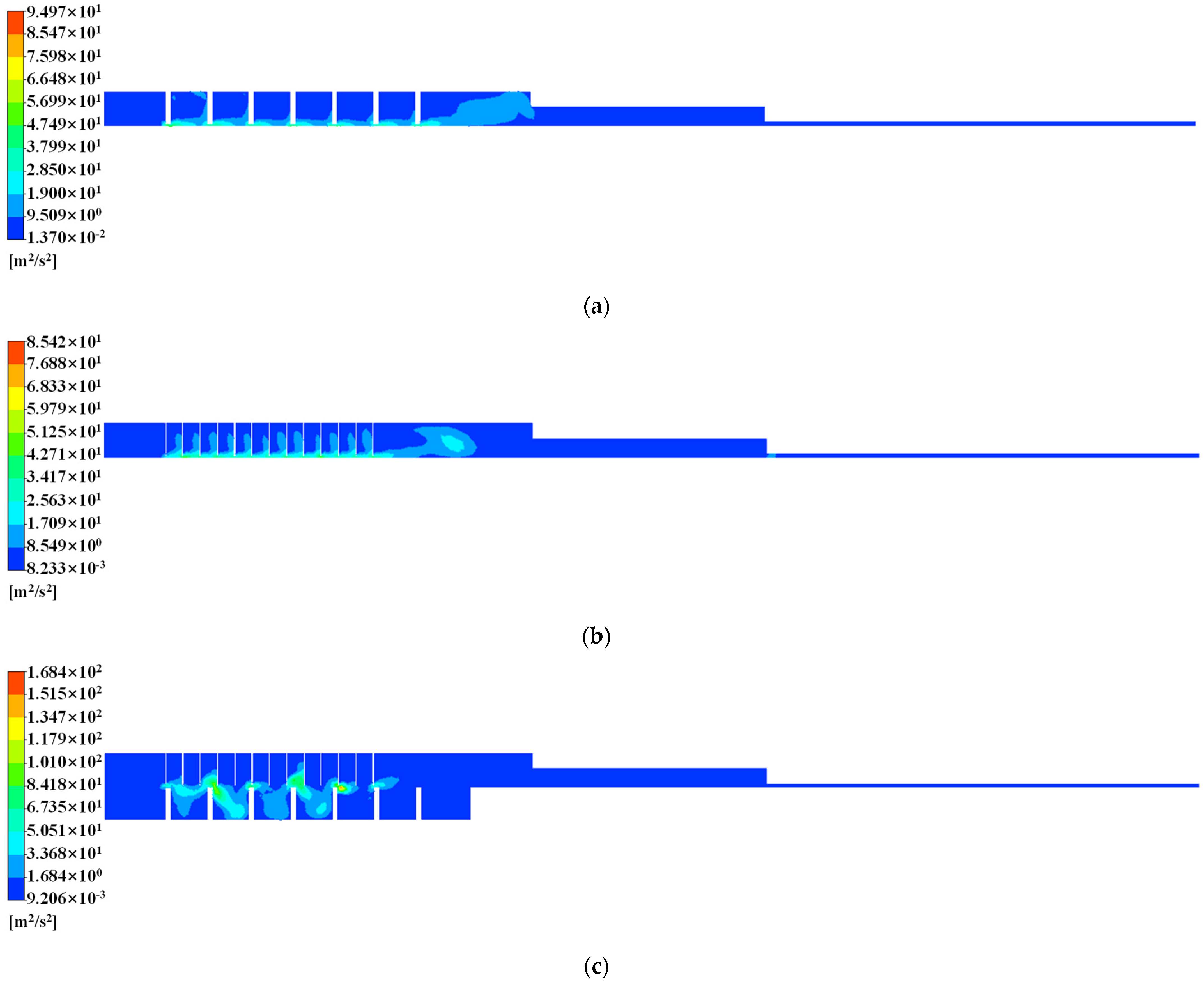
Figure 9 shows the pressure distribution of the labyrinth seal, honeycomb seal, and hybrid labyrinth–honeycomb seal when the REL = 0.1 mm. By comparing Figure 5 and Figure 9, it can be found that the eccentricity has little effect on the axial pressure distribution of the flow field. However, it can be found from Figure 10 that, compared with the case without eccentricity, the turbulent kinetic energy significantly increased when REL = 0.1 mm, indicating that the internal energy converted by the kinetic energy of the gas was reduced, and the effect of energy dissipation became worse. That is, the eccentricity will weaken the performance of the seal to dissipate gas energy and increase the leakage of the seal.
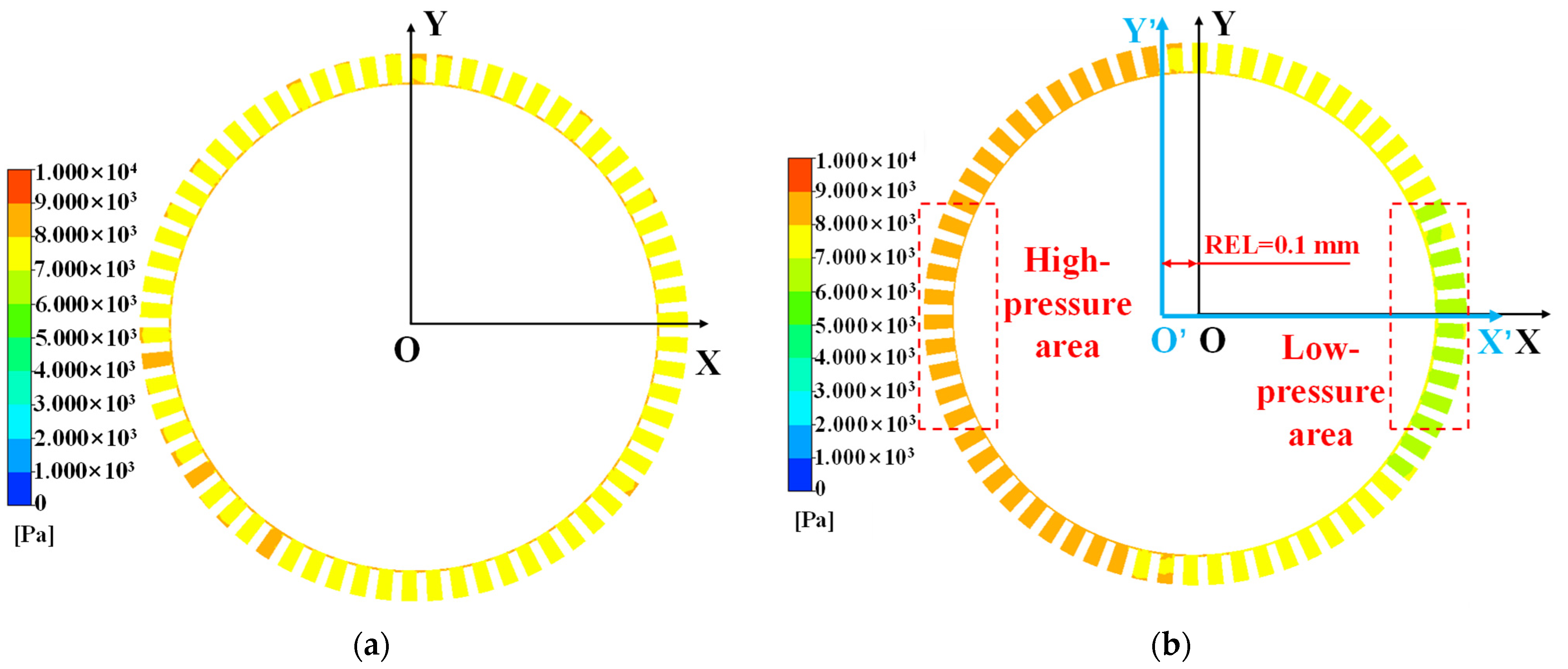
Taking a honeycomb seal as an example, the effect of radial eccentricity on the seal flow field is illustrated. Figure 11 shows the pressure distribution in the radial direction of the honeycomb seal with or without eccentricity. When there is no eccentricity, the pressure distribution of the honeycomb seal in the radial direction is uniform. When REL = 0.1 mm, the radial clearance in the direction of the rotor eccentricity decreases, and a high-pressure area appears, while the radial clearance in the opposite direction increases, and a low-pressure area appears. This leads to uneven radial pressure distribution, resulting in reduced energy consumption from gas dissipation, increased turbulent kinetic energy, and ultimately an increase in honeycomb seal leakage.
Therefore, in the case of radial eccentricity, due to uneven radial pressure distribution, the turbulent kinetic energy of the seal will increase. The turbulent kinetic energy of the honeycomb seal is the smallest, followed by the labyrinth seal, and the hybrid labyrinth–honeycomb seal is the largest. Therefore, under the same radial installation error, the leakage of the hybrid labyrinth–honeycomb seal is the largest, followed by the labyrinth seal, and the honeycomb seal is the smallest.

3. Introduction of the Experiment System

3.1. Introduction of Experiment Device

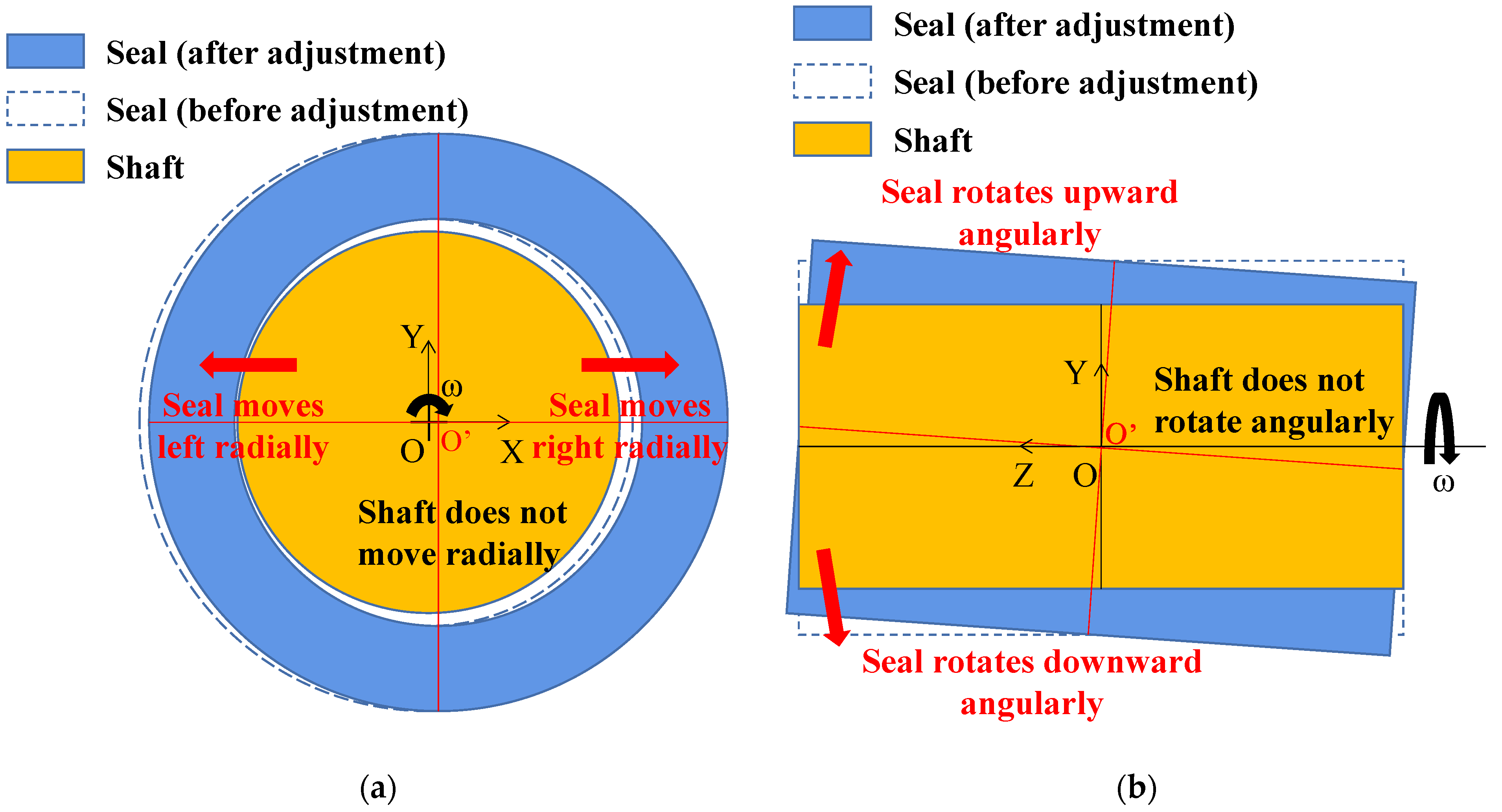
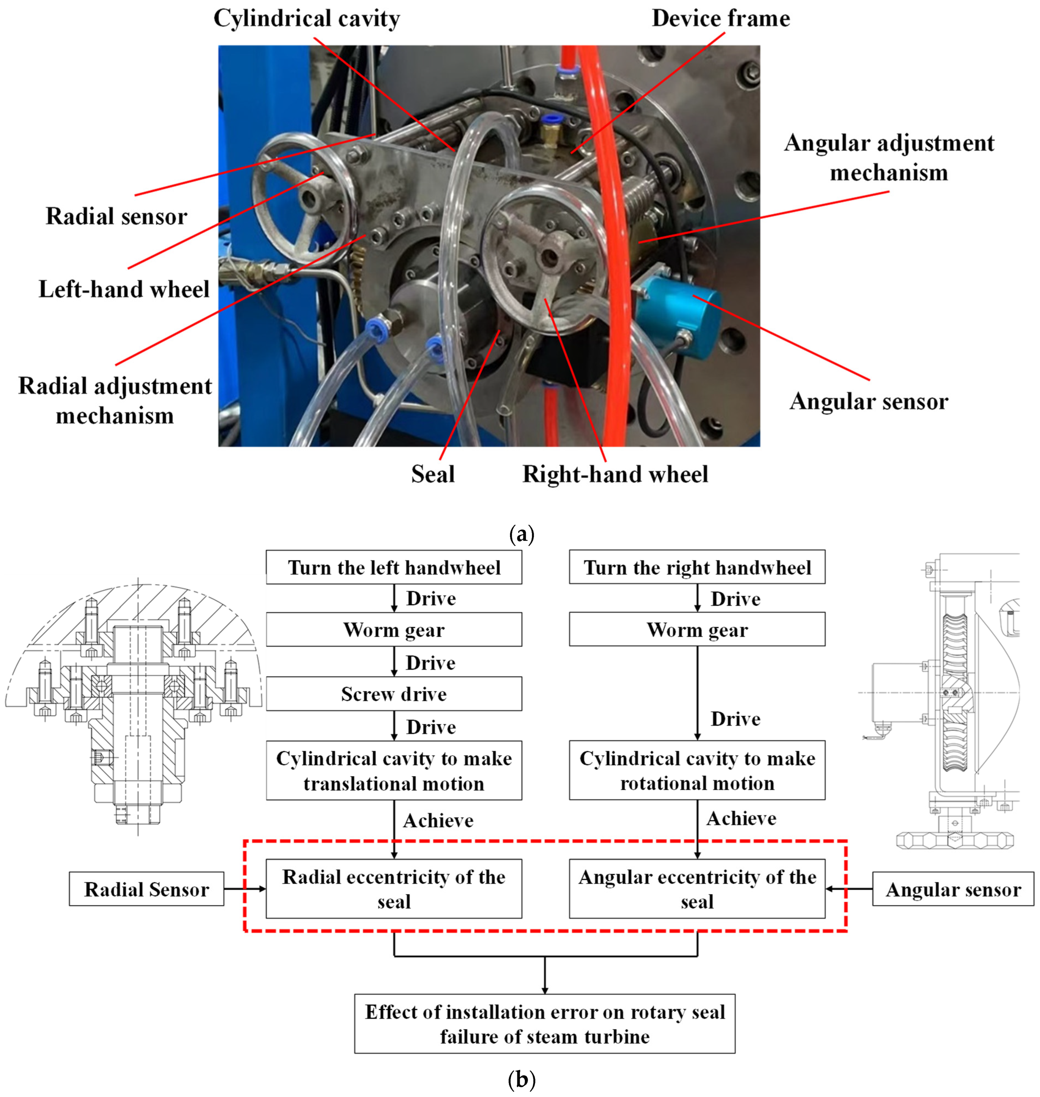
In this research, the experiment section of the high-pressure and high-speed rotary seal experiment bench is improved, and the adjustment device is designed. The adjustment device can be used to carry out the leakage characteristics experiment research of the honeycomb seal, labyrinth seal, and hybrid labyrinth–honeycomb seal under installation error conditions. The accurate construction of installation error (radial and angular eccentricity) environments can be realized through the adjustment device. The construction principle of the installation error environment is shown in Figure 12, and the adjustment device is shown in Figure 13.
The adjustment device adopts two pairs of worm gear mechanisms to control the movement and rotation of the cylindrical cavity, respectively. The cylindrical cavity and the seal are arranged in a cross-head type. After adjustment by the left-hand wheel and right-hand wheel, the cylindrical cavity drives the seal and shaft (not shown in Figure 13) to form radial and angular eccentricity. The specific adjustment amount or eccentricity can be designed according to the reduction ratio of the worm gear. In addition, the self-locking nature of the worm gear ensures that the built eccentric environment is accurate and reliable. Finally, a precise small grating measurement system (model: MWS30) and a high-precision single-turn absolute angle sensor (model: BL50B) are arranged on the adjustment device to realize the electronic measurement of the adjustment amount. Using the adjustment device, the experiment bench can carry out the leakage experiment on three types of seals under different pressures, different rotational speeds, and different installation errors.
The left cross-section in Figure 13b is the local view of the radial eccentricity adjustment mechanism. The precise small grating measurement system (not shown) is installed in the rotary shaft and fixed by the fastening screw (not shown), and the precise small grating measurement system probe is always fitted with the cylindrical cavity. The thread sleeve is installed on the cylindrical cavity by connecting screws, and the rotary shaft and the thread sleeve are connected by threads. The bearing seat is fixedly installed on the device frame by screws, and the outer ring of the bearing is installed on the bearing seat by capping and screws. Fix the bearing inner ring on the shaft shoulder of the rotary shaft with fastening screws and transmission sleeves. The worm wheel (not shown) is connected to the transmission sleeve by a transmission key (not shown).
The right cross-section in Figure 13b is the local view of the angular eccentricity adjustment mechanism. The high-precision single-turn absolute angle sensor is fixedly installed on the frame connected to the device frame and is connected to the cylindrical cavity through the rotary shaft on it. The rotary shaft can slide axially relative to the cylindrical cavity. Through the radial adjustment of the worm wheel and the worm, the right-hand wheel adjusts the micro-angle of the cylindrical cavity, which is then measured by the high-precision single-turn absolute angle sensor in real-time.

3.2. Introduction of Experiment Seals

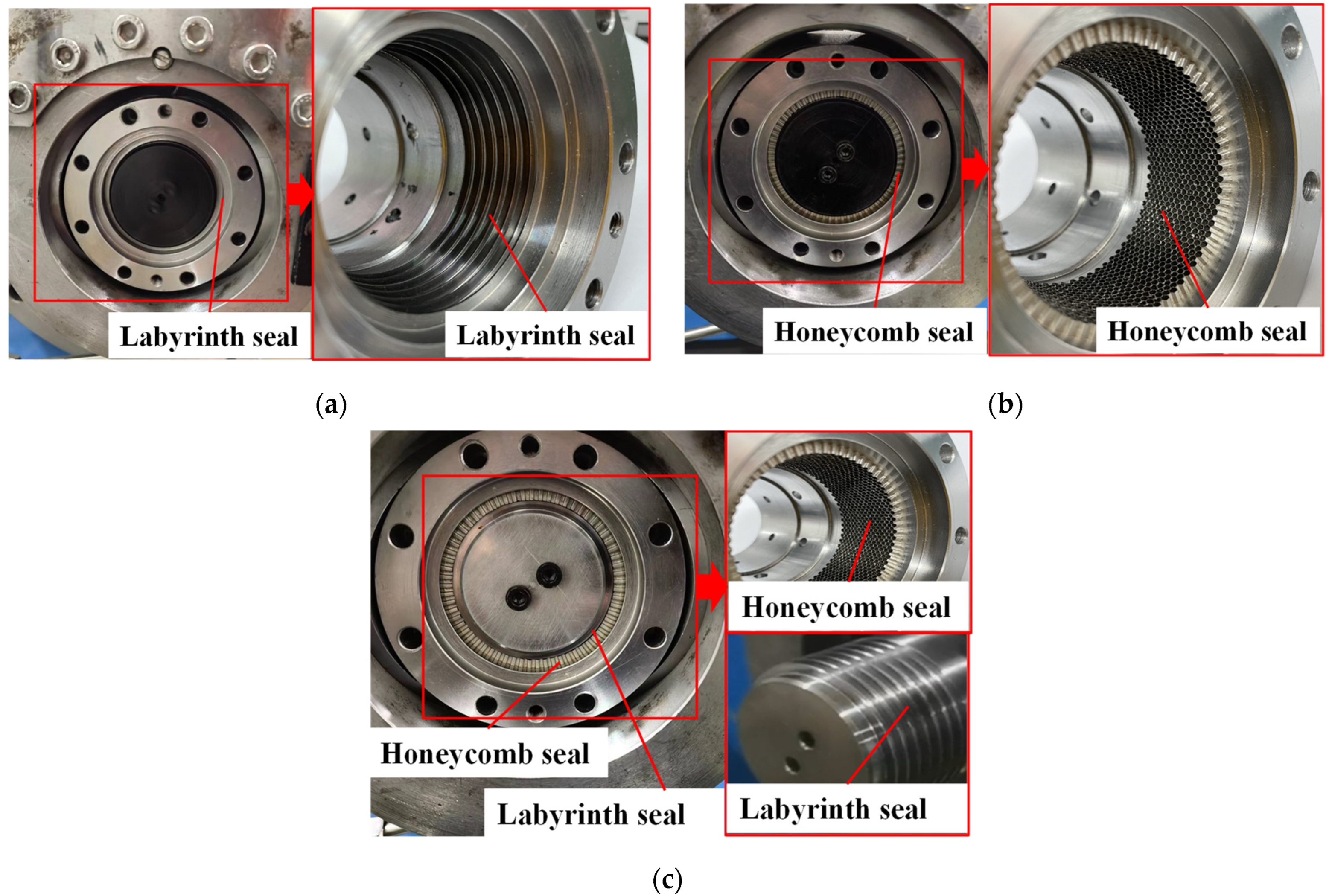
The seals to be studied in this experiment are honeycomb seals, labyrinth seals, and hybrid labyrinth–honeycomb seals; these three types of seals are processed according to the relevant structural parameters described in Section 2.1.1, and the processed seals are shown in Figure 14.

3.3. Introduction of Experiment Plan

The gas in the experiment in this research is input by the fan. Before entering the experiment device, the gas temperature is measured by a thermocouple sensor, the total gas pressure is measured by a pitot tube, and the gas flow rate entering the test device is measured by a flowmeter. After the temperature, pressure, and flow are measured, the gas enters from the end cover at the front end of the experiment device. One of the three types of seals is placed in the middle of the experimental device. The radial and angular eccentricities of the seals can be changed by adjusting the adjustment device so as to obtain the leakage of the three seals under different eccentricities.

4. Experimental Analysis of Seal Leakage Characteristics

After revealing the sealing mechanisms of the labyrinth seal, honeycomb seal, and hybrid labyrinth–honeycomb seal through numerical simulation and studying the effect of radial eccentricity on the leakage characteristics of these three types of seals, the effect of radial and angular eccentricity on the leakage characteristics of these three types of seals through experiments was further studied, thus completing the verification of the numerical simulation results.

4.1. Verification of Theoretical Analysis Results of Seal Flow Field

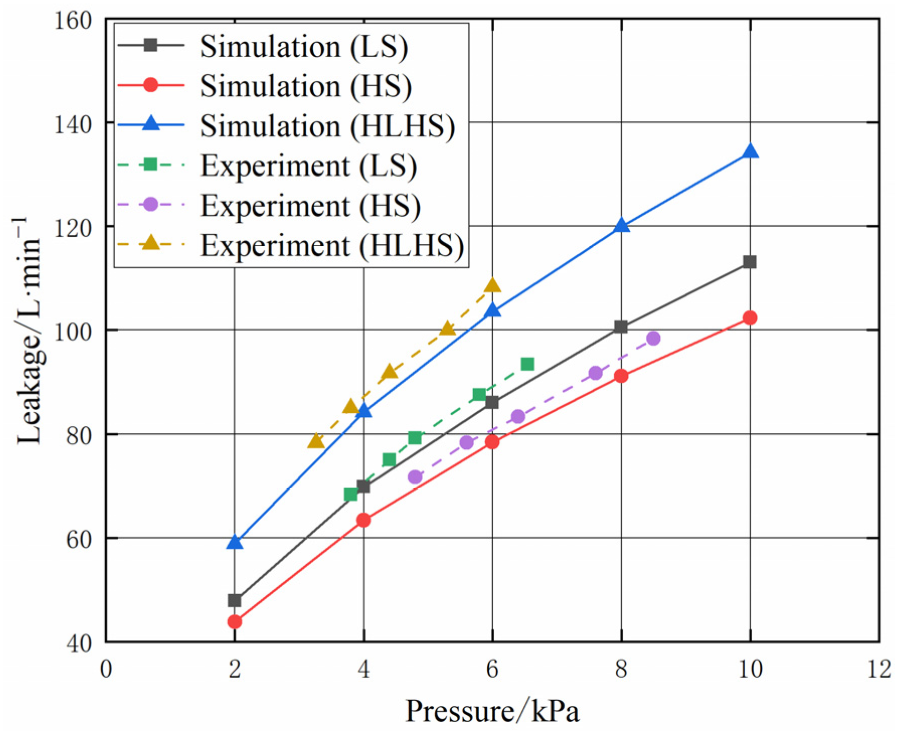
The leakage results of the labyrinth seal, honeycomb seal, and hybrid labyrinth–honeycomb seal without eccentricity are shown in Figure 15. Compared with the experimental results, the maximum error of the labyrinth seal numerical simulation results is 3.6%, the maximum error of the honeycomb seal numerical simulation results is 4.5%, and the maximum error of the hybrid labyrinth–honeycomb seal numerical simulation results is 4.4%. The numerical simulation results of the three types of seals are consistent with the experimental results, which verifies the accuracy of the seal flow field numerical model. Therefore, the results of the theoretical analysis of the seal flow field are reliable.
The relationship between the three types of seal leakage is as follows: the leakage of the hybrid labyrinth–honeycomb seal is the largest, the leakage of a labyrinth seal is the second, and the leakage of the honeycomb seal is the smallest. Compared with the honeycomb seal, the leakage of the labyrinth seal increases by about 10.2%, and the leakage of the hybrid labyrinth–honeycomb seal increases by about 34.0%. Additionally, as the pressure increases, the leakage of the three seals increases approximately linearly. For every 1 kPa increase in the pressure, the leakage of the labyrinth seal increases by about 8.0 L·min−1, the leakage of the honeycomb seal increases by about 7.3 L·min−1, and the leakage of the hybrid labyrinth–honeycomb seal increases by about 9.4 L·min−1.

4.2. Analysis of Seal Leakage Characteristics under Eccentricity

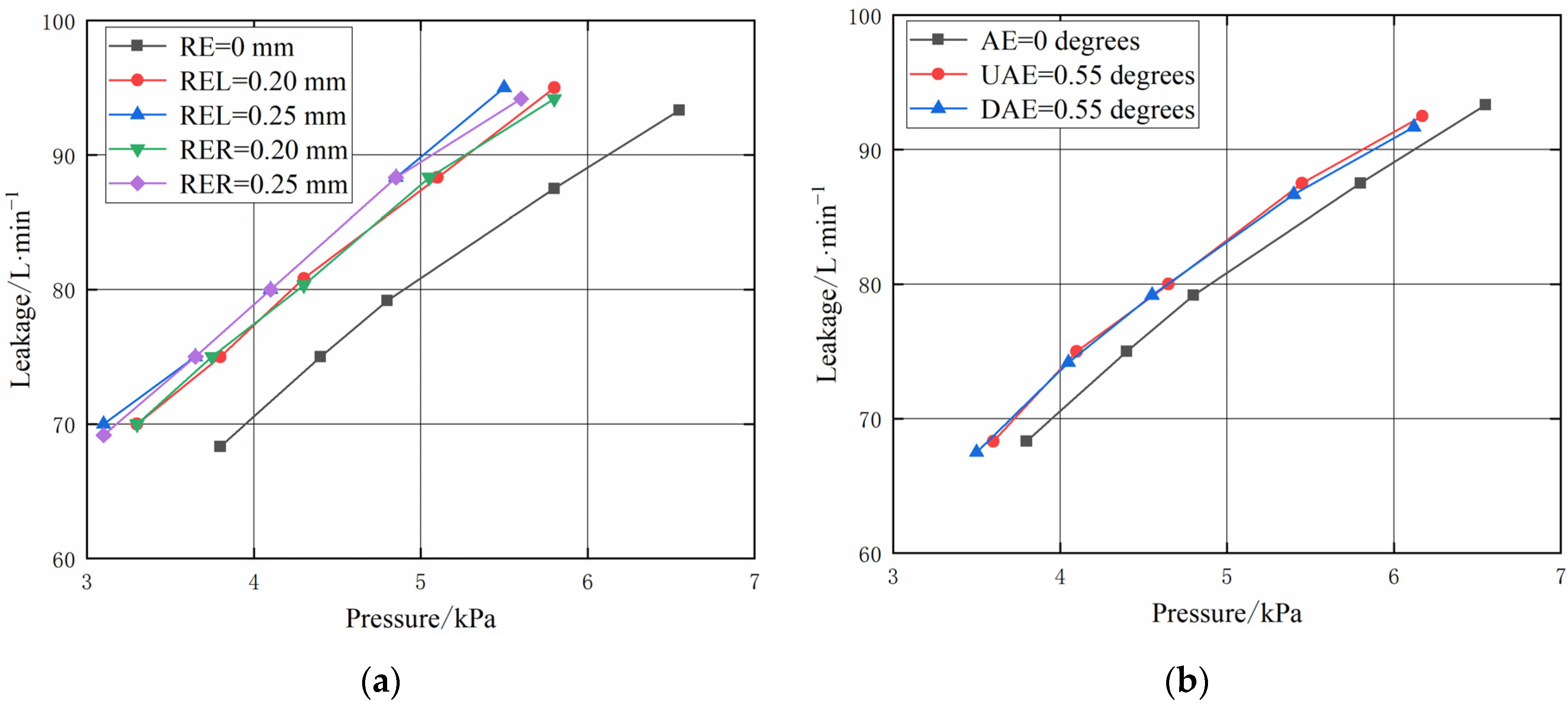
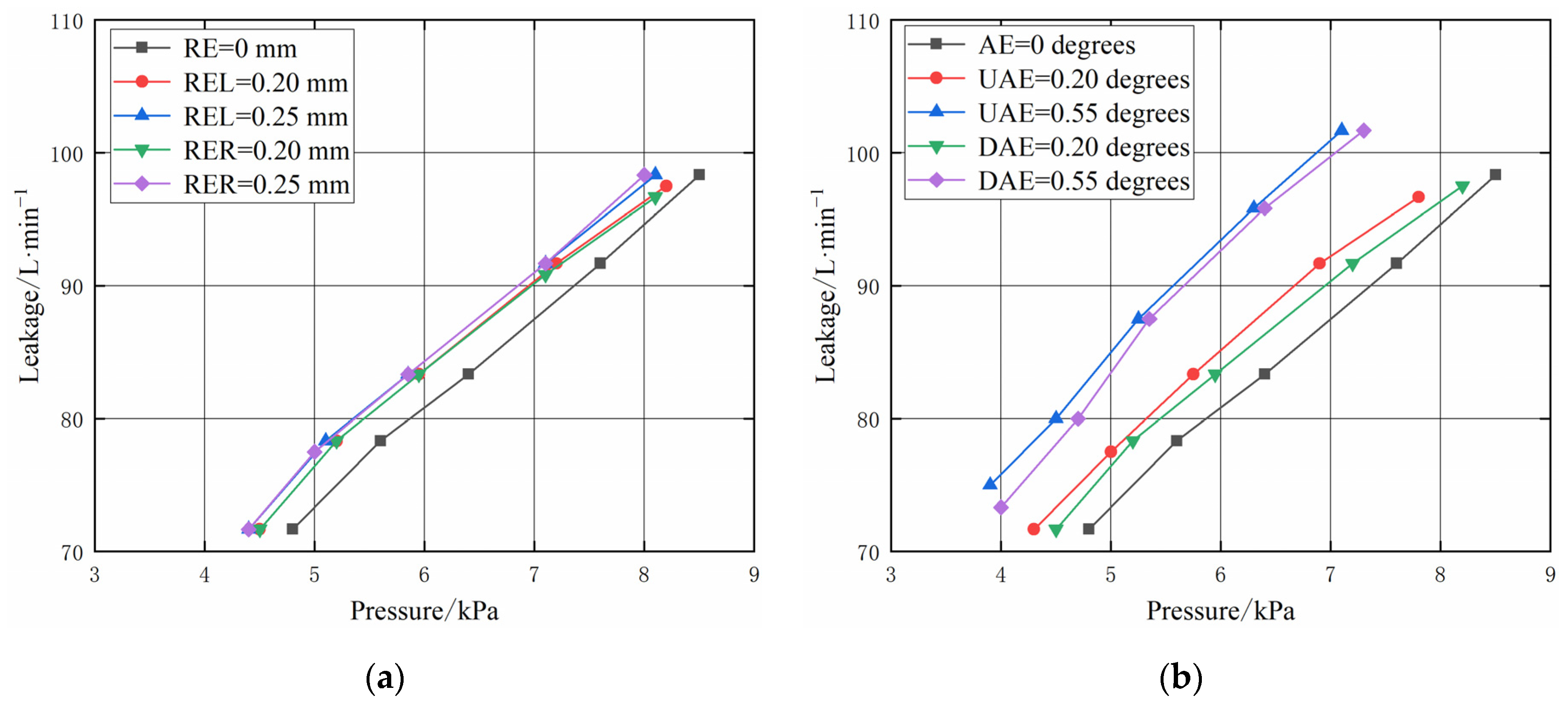
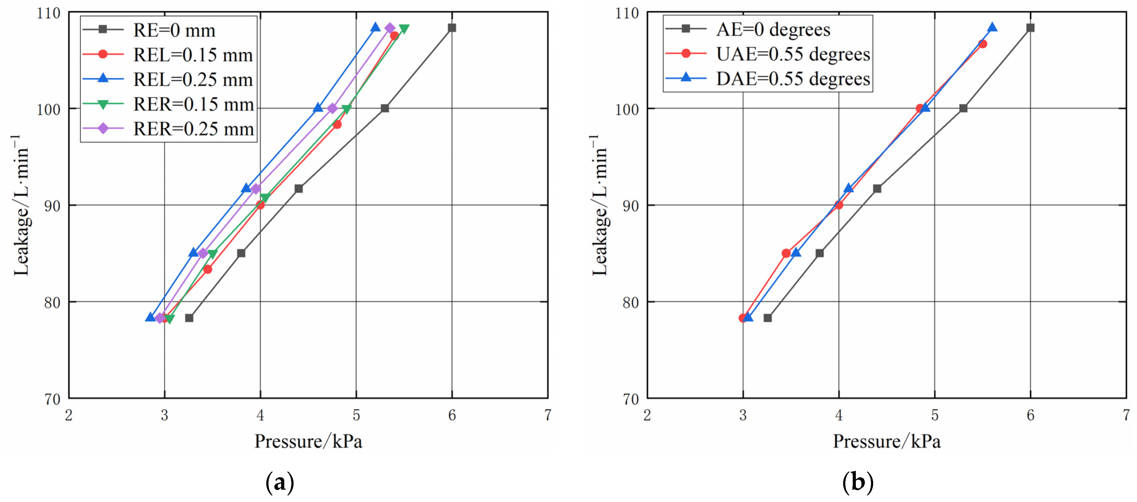
As shown in Figure 16a, Figure 17a and Figure 18a, no matter whether considering the labyrinth seal, honeycomb seal, or hybrid labyrinth–honeycomb seal, when the radial installation error (radial eccentricity) is constant, the leakage of the radial installation error to the left is basically the same as that to the right; that is, the leakage of the seal is only related to the size of the radial installation error, and the leakage of the seal is positively related to the radial installation error. When the radial installation error is at its maximum, the leakage of the labyrinth seal increases by about 12.2% compared with that without radial installation error, the leakage of the honeycomb seal increases by about 5.3% compared with that without radial installation error, and the leakage of the hybrid labyrinth–honeycomb seal increases by about 7.8% compared with that without radial installation error. Therefore, when the radial installation errors are the same, the leakage growth rate of the labyrinth seal is the largest, the leakage growth rate of the hybrid labyrinth–honeycomb seal is the second, and the leakage growth rate of the honeycomb seal is the smallest.
As shown in Figure 16b, Figure 17b and Figure 18b, it is similar to the radial installation error; when the angular installation error (angular eccentricity) is constant, the leakage of the angular installation error to the upward is basically the same as that to the downward; that is, the seal leakage is only related to the angular installation error, and the seal leakage is positively related to the angular installation error. When the angular installation error is maximum, the leakage of the labyrinth seal increases by 3.9% compared with that without angular installation error, the leakage of the honeycomb seal increases by 15.8% compared with that without angular installation error, and the leakage of the hybrid labyrinth–honeycomb seal increases by 5.0% compared with that without angular installation error. Therefore, when the angular installation errors are the same, the leakage growth rate of the honeycomb seal is the largest, the leakage growth rate of the hybrid labyrinth–honeycomb seal is the second, and the leakage growth rate of the labyrinth seal is the smallest.

4.3. Comparison of Seal Leakage Characteristics of Three Types of Seals

As shown in Figure 19a, when the radial installation error (radial eccentricity) of the honeycomb seal is the largest, its leakage is still smaller than that of the labyrinth seal without radial installation error. When the radial installation error of the labyrinth seal is the largest, its leakage is also smaller than that of the hybrid labyrinth–honeycomb seal without a radial installation error; that is, when there is a radial installation error, the leakage relationship among the three types of seals is as follows: the leakage of the hybrid labyrinth–honeycomb seal is the largest, followed by the labyrinth seal, and the honeycomb seal is the smallest. The conclusions of the experiment are consistent with those of the numerical simulation, and the leakage results obtained from the numerical simulation are highly consistent with those obtained from the experiment, which indicates that the theoretical analysis results are reliable.
As shown in Figure 19b, when the angular installation error (angular eccentricity) of the honeycomb seal and labyrinth seal is at its maximum, the leakage of both seals is basically the same. When the angular installation error of the labyrinth seal is maximum, the leakage is also smaller than that of the hybrid labyrinth–honeycomb seal without angular installation error; that is, when there is an angular installation error, the leakage relationship among the three types of seals is as follows: the leakage of the hybrid labyrinth–honeycomb seal is the largest, followed by the labyrinth seal, and the honeycomb seal is the smallest. To sum up, in case of installation error, the leakage relationship among the three types of seals is as follows: the leakage of the hybrid labyrinth–honeycomb seal is the largest, followed by the labyrinth seal, and the honeycomb seal is the smallest. Therefore, the honeycomb seal can better adapt to eccentricity. In the presence of eccentricity, a honeycomb seal should be preferred.

5. Conclusions

Because the rotary seal is prone to eccentricity and other installation errors during installation, when a large eccentricity occurs, it may lead to a large amount of gas leakage, resulting in a decrease in aero engine efficiency, which ultimately affects the reliability and life of the aero engine. Therefore, this research studies the effect of installation error (eccentricity) on aero engine rotary seals. The specific conclusions are as follows:
(1)
The numerical simulation results show that the turbulent kinetic energy of the gas in the honeycomb seal is the smallest, the turbulent kinetic energy of the gas in the labyrinth seal is the second, and the turbulent kinetic energy of the gas in the hybrid labyrinth–honeycomb seal is the largest. It shows that under the same working conditions, the kinetic energy of the gas in the honeycomb seal is converted into the most internal energy and the most fully dissipated. The kinetic energy of the gas in the hybrid labyrinth–honeycomb seal is converted into the least internal energy and the worst energy dissipation effect. Therefore, the seal performance of the honeycomb seal is better than that of the labyrinth seal, and the seal performance of the labyrinth seal is better than that of the hybrid labyrinth–honeycomb seal;
(2)
The experiment results show that when the radial installation error (radial eccentricity) is maximum, the leakage of the labyrinth seal increases by about 12.2% compared with that without radial installation error, the leakage of the honeycomb seal increases by about 5.3% compared with that without radial installation error, and the leakage of the hybrid labyrinth–honeycomb seal increases by about 7.8% compared with that without radial installation error;
(3)
The experiment results show that when the angular installation error (angular eccentricity) is maximum, the leakage of the labyrinth seal increases by 3.9% compared with that without angular installation error, the leakage of the honeycomb seal increases by 15.8% compared with that without angular installation error, and the leakage of the hybrid labyrinth–honeycomb seal increases by 5.0% compared with that without angular installation error;
(4)
The numerical simulation and experimental results show that, when there is installation error (eccentricity), the leakage relationship among the three types of seals is as follows: the leakage of the hybrid labyrinth–honeycomb seal is the largest, followed by the labyrinth seal, and the honeycomb seal is the smallest. Therefore, the honeycomb seal can better adapt to eccentricity. In the presence of eccentricity, a honeycomb seal should be preferred.

Author Contributions

Software, H.Z. and T.C.; Validation, C.L. and W.W.; Formal analysis, C.L.; Writing—original draft, C.L.; Writing—review & editing, C.L., L.H. and X.J.; Project administration, X.J.; Funding acquisition, L.H. All authors have read and agreed to the published version of the manuscript.

Funding

The project was supported by the National Science and Technology Major Project (2017-IV-0010-0047), the Beijing Natural Science Foundation (3224066).

Data Availability Statement

Data is contained within the article.

Conflicts of Interest

We declare that we have no financial and personal relationships with other people or organizations that can inappropriately influence our work. There is no professional or other personal interest of any nature or kind in any product, service and/or company that could be construed as influencing the position presented in, or the review of the current manuscript.

Nomenclature

BThe honeycomb cell diameter, mm
bThe honeycomb cell wall thickness, mm
cThe seal radius clearance, unit: mm
dLSThe diameter of shaft of labyrinth seal, mm
dHSThe diameter of shaft of honeycomb seal, mm
dHLHSThe diameter of shaft of hybrid labyrinth–honeycomb seal, mm
hThe seal depth, mm
TThe tooth spacing, mm
tThe tooth thickness, mm
Abbreviation
AEAngular eccentricity, degree
DAEDownward angular eccentricity, degree
HLHSHybrid labyrinth–honeycomb seal
HSHoneycomb seal
LSLabyrinth seal
RERadial eccentricity, mm
RELRadial eccentricity to the left, mm
RERRadial eccentricity to the right, mm
UAEUpward angular eccentricity, unit: degree

References

  1. Yang, Y.C.; Mi, Z.G.; Zhang, W.C.; Chang, J.Q.; Liu, Y.J.; Zhong, B.T.; Yang, W.H. Experimental Study on the Effect of Rubbing Mode on Radial Crack Initiation in Labyrinth Seal Fins of Shrouded Turbine Blade. Aerospace 2022, 9, 441. [Google Scholar] [CrossRef]
  2. Munz, O.; Pychynski, T.; Schwitzke, C.; Bauer, H. Continued Experimental Study on the Friction Contact between a Labyrinth Seal Fin and a Honeycomb Stator: Slanted Position. Aerospace 2018, 5, 82. [Google Scholar] [CrossRef] [Green Version]
  3. Song, X.L.; Liu, M.H.; Hu, X.P.; Wang, X.L.; Liao, T.H.; Sun, J.F. Numerical Analysis of Flow across Brush Elements Based on a 2-D Staggered Tube Banks Model. Aerospace 2021, 8, 19. [Google Scholar] [CrossRef]
  4. Wang, W.Z.; Liu, Y.Z. Analysis of the sealing performance and creep behavior of the inner casing of a 1000 MW supercritical steam turbine under bolt relaxation. Eng. Fail. Anal. 2015, 57, 363–376. [Google Scholar] [CrossRef]
  5. Wang, W.B.; Pang, X.L.; Zheng, C.Z.; Volinsky, A.A. Failure analysis of high nickel alloy steel seal ring used in turbomachinery. Eng. Fail. Anal. 2017, 80, 49–56. [Google Scholar] [CrossRef] [Green Version]
  6. Nayak, K.C. Effect of rotation on leakage and windage heating in labyrinth seals with honeycomb lands. J. Eng. Gas Turbines Power 2020, 142, 081001. [Google Scholar] [CrossRef]
  7. Childs, D.W.; Moyer, D.S. Vibration characteristics of the HPOTP (high-pressure oxygen turbopump) of the SSME (space shuttle main engine). J. Eng. Gas Turbines Power 1985, 107, 152–159. [Google Scholar] [CrossRef] [Green Version]
  8. Gu, C.J.; Zhang, W.F.; Yang, X.C.; Cao, H.; Li, C. Effect of inlet preswirl and hole arrangement patterns on the dynamic characteristics of honeycomb seals. Chin. Soc. Electr. Eng. 2021, 41, 4208–4217. [Google Scholar]
  9. Qin, B.P.; Zhang, W.F.; Cao, H.; Yin, L.; Wang, Y.F.; Li, C. Static and dynamic characteristics of eccentric labyrinth seals. Tribology 2020, 40, 735–745. [Google Scholar]
  10. Kamouni, M. Prediction of leakage flow and rotordynamic characteristics for an eccentric labyrinth gas seal. J. Eng. Sci. Technol. 2017, 12, 2922–2938. [Google Scholar]
  11. Pugachev, A.O.; Kleinhans, U.; Gaszner, M. Prediction of rotordynamic coefficients for short labyrinth gas seals using computational fluid dynamics. J. Eng. Gas Turbines Power 2012, 134, 062501. [Google Scholar] [CrossRef]
  12. Untaroiu, A.; Morgan, N.; Hayrapetian, V.; Schiavello, B. Dynamic response analysis of balance drum labyrinth seal groove geometries optimized for minimum leakage. J. Vib. Acoust. 2017, 139, 021014. [Google Scholar] [CrossRef]
  13. Yahyai, M.A.; Mba, D. Rotor dynamic response of a centrifugal compressor due to liquid carry over: A case study. Eng. Fail. Anal. 2014, 45, 436–448. [Google Scholar] [CrossRef]
  14. Teran, L.A.; Roa, C.V.; Muñoz-Cubillos, J.; Aponte, R.D.; Valdes, J.; Larrahondo, F.; Rodríguez, S.A.; Coronado, J.J. Failure analysis of a run-of-the-river hydroelectric power plant. Eng. Fail. Anal. 2016, 68, 87–100. [Google Scholar] [CrossRef]
  15. Li, W.; Wang, X.; Zhang, X.H.; Zhang, X.J.; Zhu, Y.L.; Chen, H.S. Experimental and numerical investigations of closed radial inflow turbine with labyrinth seals. J. Eng. Gas Turbines Power 2018, 140, 102502. [Google Scholar] [CrossRef]
  16. Jia, X.Y.; Zheng, Q.; Jiang, Y.T.; Zhang, H. Leakage and rotordynamic performance of T type labyrinth seal. Aerosp. Sci. Technol. 2019, 88, 22–31. [Google Scholar] [CrossRef]
  17. Flouros, M.; Cottier, F.; Hirschmann, M.; Salpingidou, C. Numerical Investigation on Windback Seals Used in Aero Engines. Aerospace 2018, 5, 12. [Google Scholar] [CrossRef] [Green Version]
  18. Kong, X.Z.; Liu, G.W.; Liu, Y.X.; Zheng, L.X. Experimental testing for the influences of rotation and tip clearance on the labyrinth seal in a compressor stator well. Aerosp. Sci. Technol. 2017, 71, 556–567. [Google Scholar] [CrossRef]
  19. Zhao, Y.Z.; Wang, C.H. Shape Optimization of Labyrinth Seals to Improve Sealing Performance. Aerospace 2021, 8, 92. [Google Scholar] [CrossRef]
  20. Yang, X.C.; Zhang, W.F.; Gu, C.J.; Zhang, X.B.; Li, C. Leakage performance and static stability of hybrid labyrinth-honeycomb seals. Tribology 2021, 41, 738–748. [Google Scholar]
  21. Childs, D.; Elrod, D.; Hale, K. Annular honeycomb seals: Test results for leakage and rotordynamic coefficients; comparisons to labyrinth and smooth configurations. J. Eng. Gas Turbines Power 1989, 111, 293–300. [Google Scholar] [CrossRef] [Green Version]
  22. Soulas, T.; Andres, L.S. A bulk flow model for off-centered honeycomb gas seals. J. Eng. Gas Turbines Power 2007, 129, 185–194. [Google Scholar] [CrossRef]
  23. Zhao, H.; Zhang, R.; Sun, D.; Zhou, M. Influence Factors of Honeycomb Seal Performance and Stability Analysis of Rotor System. J. Aerosp. Eng. 2022, 35, 04022042. [Google Scholar] [CrossRef]
  24. Liu, C.R.; Yan, Z.; Wang, X.Z.; He, L.D.; Jia, X.Y.; Wang, W.H. Research on the influence of honeycomb cell blockage on the seal leakage characteristics. Int. J. Turbo Jet Eng. 2022. [Google Scholar] [CrossRef]
  25. Li, J.; Kong, S.R.; Yan, X.; Obi, S.; Feng, Z.P. Numerical investigations on leakage performance of the rotating labyrinth honeycomb seal. J. Eng. Gas Turbines Power 2010, 132, 062501. [Google Scholar] [CrossRef]
  26. Yan, X.; Li, J.; Feng, Z.P. Effects of inlet preswirl and cell diameter and depth on honeycomb seal characteristics. J. Eng. Gas Turbines Power 2010, 132, 122506. [Google Scholar] [CrossRef]
  27. Li, Z.G.; Li, J.; Feng, Z.P. Numerical investigations on the leakage and rotordynamic characteristics of pocket damper seals-part I: Effects of pressure ratio, rotational speed, and inlet preswirl. J. Eng. Gas Turbines Power 2015, 137, 032503. [Google Scholar] [CrossRef]
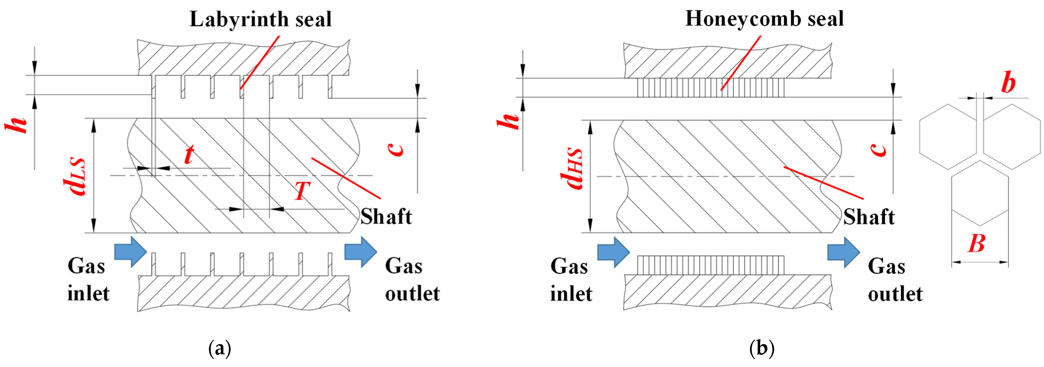
Figure 1. Structural diagram of three types of seals. (a) Labyrinth seal; (b) honeycomb seal; (c) hybrid labyrinth–honeycomb seal.
Aerospace 09 00820 g001aAerospace 09 00820 g001b
Figure 2. Schematic diagram of radial eccentricity of seal.
Aerospace 09 00820 g002
Figure 3. Seal flow field numerical models. (a) Labyrinth seal; (b) honeycomb seal; (c) hybrid labyrinth–honeycomb seal.
Aerospace 09 00820 g003
Figure 4. Leakage results of three types of seals (RE = 0 mm).
Aerospace 09 00820 g004
Figure 5. Pressure distribution diagram of three types of seals (RE = 0 mm). (a) Labyrinth seal; (b) honeycomb seal; (c) hybrid labyrinth–honeycomb seal.
Aerospace 09 00820 g005aAerospace 09 00820 g005b
Figure 6. Turbulent kinetic energy diagram of three types of seals (RE = 0 mm). (a) Labyrinth seal; (b) honeycomb seal; (c) hybrid labyrinth–honeycomb seal.
Aerospace 09 00820 g006
Figure 7. Leakage of three types of seals under different radial eccentricities. (a) Labyrinth seal; (b) honeycomb seal; (c) hybrid labyrinth–honeycomb seal.
Aerospace 09 00820 g007
Figure 8. Leakage of three types of seals under different radial eccentricities.
Aerospace 09 00820 g008
Figure 9. Pressure distribution diagram of three types of seals (REL = 0.1 mm). (a) Labyrinth seal; (b) honeycomb seal; (c) hybrid labyrinth–honeycomb seal.
Aerospace 09 00820 g009
Figure 10. Turbulent kinetic energy diagram of three types of seals (REL = 0.1 mm). (a) Labyrinth seal; (b) honeycomb seal; (c) hybrid labyrinth–honeycomb seal.
Aerospace 09 00820 g010
Figure 11. Radial pressure distribution diagram of honeycomb seal. (a) RE = 0 mm; (b) REL = 0.1 mm.
Aerospace 09 00820 g011
Figure 12. Installation error environment adjustment principle (radial and angular eccentricity). (a) Radial eccentric adjustment principle; (b) angular eccentric adjustment principle.
Aerospace 09 00820 g012
Figure 13. Adjustment device with precise adjustment, self-locking, and electronic measurement. (a) Adjustment device; (b) principle of adjustment device.
Aerospace 09 00820 g013
Figure 14. Physical picture of three types of seals. (a) Labyrinth seal; (b) honeycomb seal; (c) hybrid labyrinth–honeycomb seal.
Aerospace 09 00820 g014
Figure 15. Comparison of numerical simulation and experimental results of three types of seals (RE = 0 mm).
Aerospace 09 00820 g015
Figure 16. Leakage of labyrinth seal under different eccentricities. (a) Radial eccentricity; (b) angular eccentricity.
Aerospace 09 00820 g016
Figure 17. Leakage of honeycomb seal under different eccentricities. (a) Radial eccentricity; (b) angular eccentricity.
Aerospace 09 00820 g017
Figure 18. Leakage of hybrid labyrinth–honeycomb seal under different eccentricities. (a) Radial eccentricity; (b) angular eccentricity.
Aerospace 09 00820 g018
Figure 19. Leakage of three types of seals under different eccentricities. (a) Radial eccentricity; (b) angular eccentricity.
Aerospace 09 00820 g019
Publisher’s Note: MDPI stays neutral with regard to jurisdictional claims in published maps and institutional affiliations.