Abstract
During aircraft braking, the change of ground adhesion forces can cause forward and backward vibration of the landing gear, and the performance of the brake disc may exacerbate this vibration. In order to solve this problem, a rigid–flexible coupling dynamic model of a two-wheel strut landing gear considering the friction characters of brake discs with different materials and a hydraulic brake system model is established in this paper. The brake disc friction characteristics effect on the low-frequency brake-induced vibration of the landing gear given different brake disc materials and ambient temperatures is studied. It is shown that the C/SiC brake disc has a “negative slope” phenomenon between the friction coefficient of the brake disc and the wheel speed, and this variable friction characteristic has a great effect on the low-frequency braking-induced vibration of the landing gear. In addition, the variable friction characteristics of the C/SiC brake disc are easily affected by ambient temperature, while the friction coefficient of the C/C brake disc changes stably.
1. Introduction
In the process of aircraft braking, the landing gear is affected by the combination of the braking torque and the ground adhesion torque, resulting in vibration. These vibrations can be divided into low-frequency vibration, medium-high-frequency vibration, and high-frequency vibration, which are collectively referred to as brake-induced vibration [1]. In this paper, low-frequency brake-induced vibration–gear walk is studied. Gear walk not only affects the braking efficiency of aircraft [2,3], but also affects the structural life of the aircraft landing gear. Many scholars use time domain simulation studies on gear walk. They basically ignored the friction characteristics of brake discs, and the brake disc friction coefficient is usually set to a fixed value in the research and analysis. However, the friction characteristics of brake discs will cause self-excited vibration of the landing gear under the natural state [4]. Therefore, the results of simulation analysis will be different from those obtained from actual tests. Aiming at the problem of gear walk, the brake discs friction characteristics under different materials and ambient temperatures and their effect on gear walk are studied so as to provide reference for the time domain simulation analysis of gear walk in the future.
In view of the gear walk, Gualdi [5] uses a simple main landing gear multibody model to study the application of multidisciplinary multibody modelling to the analysis of gear walk, and it is necessary to replace the parameters of each element of the landing gear with the experimental data. Avico [6] established a control-oriented dynamic model of the landing gear based on the automotive single-corner model and presented a deceleration-based control algorithm to reduce the gear walk. Balasubramanian [7] obtained a set of fourth-order and second-order nonlinear motion control differential equations for the system using the Lagrange equation of independent generalized coordinates. The reduced–scale landing gear was used for half physical simulation in order to study the influence of the landing gear structural parameters on gear walk. Yin [8] established a nonlinear dynamic model of the semi-axle landing gear to study and optimize the anti-skid brake control law between gear walk and braking efficiency. Liao [9] established a rigid–flexible coupling model of a six-wheel landing gear and analyzed the characteristics of gear walk. Khapane [10] established a flexible model of the landing gear by using SIMPACK to study the influence of different anti-skid brake control law parameters on characteristics of gear walk. The analysis model of gear walk has gradually developed from the theoretical model to the rigid–flexible coupling dynamic model. In the time domain simulation analysis of gear walk, the influence of the landing gear structural parameters and anti-skid brake control parameters are more thoroughly considered, and the friction characteristics of the brake disc are considered less. Based on the previous research, a rigid–flexible coupling dynamic model of a two-wheel strut landing gear considering the friction characteristics of the brake disc is established in this paper in order to analyze the gear walk.
At present, research on the variable friction characteristics of brake discs is mainly in the field of railway braking. Rovira [11], based on simplified Kalker theory, established variable friction functions of brake discs and studied the influence of pressure on the friction coefficients of different functions. Lee [12] established a variable friction characteristic model of the brake disc considering the influence of temperature and analyzed the influence of brake disc variable friction characteristics on the braking performance of a train. Ehret [13] established a variable friction coefficient of a brake disc mathematical model considering the rotation speed, temperature, and normal pressure of the brake disc, studied the longitudinal motion characteristics of the train, and pointed out that the relationship between variables and the friction coefficient of the brake disc was generally nonlinear. Liu [14], based on BP neural network, established a variable friction characteristic model of a C/C brake disc considering the influence of temperature and speed and simulated the braking process of aircraft. Some references found that the variable friction characteristics of the C/SiC brake disc are different from those of a C/C brake disc by conducting friction tests on brake discs, and there is an obvious “negative slope” phenomenon between the friction coefficient of the C/SiC brake disc and the speed of the brake disc [15,16]. With the progress of C/SiC brake material manufacturing technology, the frictional properties are improved, and the negative slope phenomenon is more obvious [17,18]. Moreover, relevant references show that the existence of such a “negative slope” phenomenon will have an impact on the stability of the aircraft anti-skid brake control system [19,20]. The friction characteristics of brake discs with different materials are often ignored during the analysis of gear walk. Therefore, C/SiC and C/C brake disc variable friction models considering the influence of brake disc temperature, rotation speed, and brake pressure will be established in this paper.
The research purpose of this paper is to study the effect of brake disc friction characteristics on gear walk. In Section 2, a rigid–flexible coupling dynamic model of a two-wheel strut landing gear is established considering the friction characters of brake discs with different materials and a hydraulic brake system model. In Section 3, based on the gear walk system model established by Section 2, the effect of variable friction coefficient and constant friction coefficient on gear walk is compared, and the effects of the friction characteristics of the brake disc on gear walk are studied given different materials and ambient temperature. Based on the acceleration spectrum obtained through short-term Fourier transform, the main gear walk vibration frequency is discussed. Conclusions are drawn in Section 4.
2. The Model of Gear Walk System
2.1. The Rigid–Flexible Coupling Dynamics Model of Landing Gear
In this paper, a rigid–flexible coupling dynamics model of a two-wheel strut landing gear including the buffer force, tire force, fuselage gravity, and braking force is established in the Simcenter 3D multi-body dynamics software, as shown in Figure 1. The buffer forces include the oil damping force, air spring force, and structure limiting force.
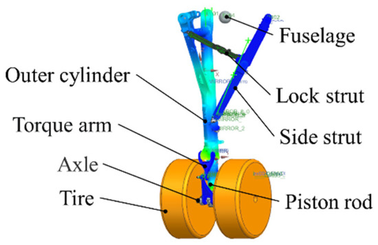
Figure 1.
Rigid–flexible coupling dynamics model of a landing gear.
The tire force includes the tire longitudinal force, lateral force, and vertical force, and the basic tire model in Simcenter 3D was used to establish the tire model required for simulation. The basic properties of the tire, such as its roll radius, tire friction coefficient, vertical stiffness, vertical damping, and cornering stiffness, can be customized through the vehicle component module in Simcenter 3D. Fuselage gravity is concentrated on the equivalent mass, and the brake torque produced by the hydraulic brake system is applied to the revolute pair between the tire and the axle.
2.1.1. Model of Buffer
The type of buffer is oil-gas, and its buffer forces mainly consists of air spring force, oil damping force, and structural limiting force. The equation for the air spring force is:
where is the effective pressure area of the air chamber, is the initial inflation pressure of the air chamber, is the initial inflation volume of the air chamber, is the distance of buffer movement, is the variable index of gas compression, and is the atmospheric pressure.
The oil damping force is the relation curve of the damping coefficient and the buffer move distance obtained by interpolation according to the experimental data, the data having been imported into Simcenter 3D and calculated by establishing a mathematical function.
where is the relation curve of the damping coefficient and the buffer movement distance and is the speed of the buffer movement.
The equation for the structural limiting force is:
where is the structural limiting stiffness and is the maximum compression distance.
2.1.2. Flexible Processing and Constraint Relations
For the analysis of gear walk, the flexibility of the rigid body model can better simulate the elastic deformation and the load transfer of landing gear struts. It is not necessary to concentrate the stiffness of the landing gear struts into the moving pair between the landing gear and the equivalent mass, and the simulation results of the flexible model are more realistic. Therefore, in this paper, the outer cylinder, piston rod, torque arm, and side strut of the landing gear are flexible.
The constraints between the components of the landing gear model are shown in Figure 2. The red box indicates the flexible body, the black box indicates the rigid body, and the blue box indicates the constraint. When the outer cylinder and piston rod are flexible, in order to simulate the motion characteristics of the buffer, a point on a flexible curve pair is established between the outer cylinder and the piston rod. The up and down torque arms are constrained by a spherical pair, and most of the other components are constrained by revolute pairs and fixed pairs. In order to simulate the landing and braking process, there is a short distance between the tire and the ground at the initial moment, and the fuselage has a specific initial speed.
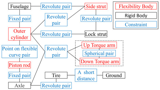
Figure 2.
Constraints between the components of the landing gear model.
2.2. Variable Friction Model of the Brake Disc
The friction coefficient of the brake disc is closely related to the brake pressure, wheel speed, and the temperature of the brake disc. This paper assumes that the brake pressure and wheel speed affect the temperature, and that this then affects the friction coefficient. The variable friction model of the brake disc is established in MATLAB/Simulink. The variable friction coefficient models of the C/C brake disc and the C/SiC brake disc are established according to the different materials in the brake disc. The variable friction model of brake disc is divided into a temperature variation model and a temperature–friction coefficient model.
2.2.1. Temperature Variation Model
The temperature variation model includes the heat rise model and the heat dissipation model [21]. The frictional heat rise and heat flux of the brake disc temperature are calculated according to the brake pressure and the relative rotation speed in the heat rise model. Based on the forced flow of air and natural convection heat transfer, the heat flux of air flow heat dissipation at a given brake disc temperature are calculated using the heat dissipation model. The internal heat change of the brake disc is calculated according to the heat flux of the brake disc heat change, and then the temperature change is calculated according to the specific heat capacity of the material and the mass of the brake disc:
where is the internal heat change of the brake disc, is the frictional heat rise/heat flux of the brake disc temperature, is the heat flux of the air flow heat dissipation at the given brake disc temperature, is the friction contact area of the brake disc, is the temperature change of the brake disc, is the specific heat capacity of the brake disc material, and is the mass of the brake disc.
The equation for calculating the frictional heat rise/heat flux of the brake disc temperature is:
where is the friction coefficient of the brake disc, is the normal pressure of the brake disc, is the brake wheel rotation speed, is the friction radius of the rotating disc, and is the friction radius of the static disc.
The equation for calculating the heat flux of the air flow heat dissipation at a given brake disc temperature is:
where is the surface heat transfer coefficient, is the temperature of the brake disc, is the ambient temperature, is the Nusselt number, is the convective heat transfer coefficient, and is the solid wall characteristic length.
During the whole braking process, the external surface of the brake disc and the air are in a state of forced flow heat transfer. The Nusselt number is calculated according to the empirical equation:
where is the Reynolds number, is the Prandtl number.
During the whole braking process, the external surfaces of the moving disc and the static disc are in a state of natural convection heat transfer in a limited space. The Nusselt number is calculated according to the empirical equation:
where is the Grashof number and the subscript is the thickness of the interlayer, subscript is used in as a qualitative temperature, and are the temperature of the interlayer at both ends of the brake disc, is the gravitational acceleration, is the volume expansion coefficient, is the difference between the surface temperature and the fluid temperature, and is the kinematic viscosity of air.
2.2.2. Temperature–Friction Coefficient Model
During braking, the heat generated causes the temperature of the brake disc to rise. The change in temperature causes the friction coefficient between the brake discs to change. The relationship between the friction coefficient and the temperature of the C/C and C/SiC brake discs is different.
For the C/C brake disc, a piecewise function is used to describe the influence of the law of temperature on the friction coefficient, and the specific equation is [22]:
where , , , , , are the correlation coefficient, is the optimum temperature, and is the limit temperature of the brake disc.
When the temperature is lower than the optimum temperature, then the friction coefficient of the brake disc increases with the increase of the brake temperature. When the temperature is the optimum temperature, then the friction coefficient of the brake disc is the largest. When the temperature is higher than the optimum temperature, then the friction coefficient of the brake disc decreases with the increase of the brake temperature, as shown in Figure 3.
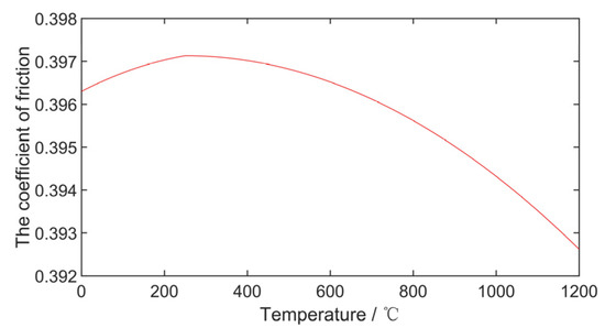
Figure 3.
Variation curve of the friction coefficient of the C/C brake disc with temperature.
For the C/SiC brake disc, an approximate fitting curve is obtained by interpolation and fitting according to the test data of relevant reference [16,17,18] in order to describe the influence of the law of temperature on the friction coefficient, as shown in Figure 4. With the increase of temperature, the friction coefficient decreases rapidly to below 0.28 and maintains a stable change. When the temperature reaches 400 °C, then the friction coefficient rises rapidly to above 0.52.
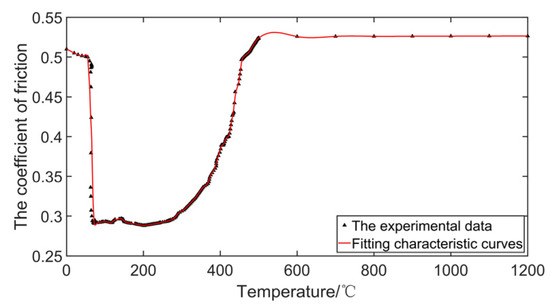
Figure 4.
Variation curve of the friction coefficient of the C/SiC brake disc with temperature.
2.3. Hydraulic Brake System Model
A slip rate PID control hydraulic anti-skid brake system is adopted in this paper, and the brake control schematic is shown in Figure 5. According to the axle speed , wheel speed , and wheel rotation radius , the wheel slip rate is calculated, the PID controller controls the difference between the optimum slip rate and the actual slip rate to generate anti-skid current , and the hydraulic system of the brake apparatus amplifies the anti-skid current, generating the corresponding brake pressure . The variable friction coefficient model calculates the brake disc temperature through the wheel speed and the brake pressure , and then it outputs the corresponding friction coefficient of the brake disc to the brake apparatus.
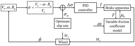
Figure 5.
Brake control principle.
Brake apparatus as shown in Figure 6. Rotating disc connected to the wheel, the rotating speeds of rotating disc and the wheel are the same. The static disc is fixed on the axle. Under the brake pressure , the friction between the rotating disc and the static disc produces the braking torque which is required for the anti-skid brake. Under the joint action of the braking torque and the ground adhesion torque , the wheel starts to brake and decelerate with the angular acceleration .
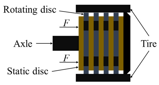
Figure 6.
Brake apparatus.
The specific calculation equation of the hydraulic brake system model is as follows:
where is the optimum slip rate ( is 0.12 in this paper), is the anti-skid current amplification factor, is the friction coefficient of the brake disc, is the friction radius of the rotating disc, is the friction radius of the static disc, is the ground support force, is the ground adhesion coefficient (by according to the “Pacejka” magic tire equation calculated in [23]), and is the wheel’s moment of inertia.
2.4. Co-Simulation Method
In this paper, the rigid–flexible coupling dynamics model of a landing gear was established in Simcenter 3D. Due to the complexity of the brake disc variable friction model and hydraulic brake model, it is difficult to established in Simcenter 3D. Therefore, the brake disc variable friction model and the hydraulic brake system model are established in MATLAB/Simulink, and the anti-skid braking control system adopts the slip rate PID control. In this paper, the co-simulation method was used to complete the data exchange between the Simcenter 3D and MATLAB/Simulink, and the data exchange process is shown in Figure 7.
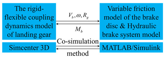
Figure 7.
Co-simulation method.
The parameters required in the simulation process are shown in the Table 1.

Table 1.
Simulation parameters.
3. Analysis of the Brake Disc Friction Characteristics Effect on Gear Walk
3.1. C/SiC Brake Disc Variable Friction Characteristics Effect on Gear Walk
The gear walk analysis model of a landing gear with a C/SiC variable friction coefficient and a constant friction coefficient were simulated, respectively. The constant friction coefficient is 0.45, and the landing gear initial speed is 70 [3]. Considering the phenomenon of the landing gear spin-up and spring-back, the hydraulic anti-skid brake system controlled by the slip rate PID would start at 2 s [24]. The simulation results for the C/SiC brake disc variable friction characteristics’ effect on gear walk are shown in Figure 8.
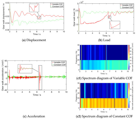
Figure 8.
C/SiC brake disc variable friction characteristics’ effect on gear walk.
The gear walk motion trend of the landing gear with constant friction coefficients is the same as that with a variable friction coefficient: the gear walk displacement vibration is more severe, and the gear walk load is weak. The displacement and acceleration of gear walk fluctuate greatly at 6 s, and at the same time, the load of gear walk rises rapidly. With a constant friction coefficient, the amplitude of the gear walk decreases slowly and tends to be stable. The addition of a variable friction coefficient model will greatly affect the gear walk, so it is necessary to consider the friction characteristics of the brake disc during gear walk analysis.
It can be seen that the acceleration fluctuates frequently. Therefore, short-term Fourier transform is used to obtain the spectrum diagram of the gear walk acceleration. The vibration frequency under variable friction conditions is mainly 20 , the vibration amplitude below 20 is about 10 to 15 , and the vibration amplitude above 20 is about 5 to 10 . The vibration frequency under constant friction conditions is the same as that under variable friction conditions. Due to the existence of variable friction characteristics, the maximum amplitude under variable friction conditions is larger than that under constant friction conditions. When the coefficient of friction is above 0.5, then the friction coefficient reaches above 0.5 and the vibration frequency remains stable.
The gear walk fluctuation phenomenon in the simulation of a C/SiC variable friction coefficient can be found in Figure 9. The temperature of the brake disc reaches to 400 °C at 6 s. It can be seen from Figure 4 that the friction coefficient of the C/SiC brake disc is in a rapidly changing stage at this time. The brake torque also starts to vibrate due to the sudden change of the C/SiC brake disc friction coefficient, which leads to the rapid increase of the load of the gear walk. The fluctuation phenomenon of the gear walk is caused by the sudden change of the C/SiC brake disc friction coefficient.
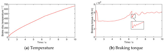
Figure 9.
Friction characteristics analysis of a C/SiC brake disc.
During the actual braking process, it is difficult to measure the temperature of the brake disc, so it is difficult to draw the relation curve between the friction coefficient and the temperature, while it is easier to obtain the wheel speed. Therefore, it is more applicable to draw the relation curve between the wheel speed and the friction coefficient of a C/SiC brake disc, as shown in Figure 10. It can be seen that there will be a phenomenon of “negative slope” between the wheel speed and the friction coefficient, which will decrease the wheel speed and increase the friction coefficient.
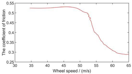
Figure 10.
Relationship between the wheel speed and the friction coefficient of a C/SiC brake disc.
In the process of aircraft braking, the wheel speed decreases and the brake disc temperature rises. With the increase of temperature, the friction coefficient decreases rapidly to below 0.28 and maintains a stable change. When the temperature reaches 400 °C, the friction coefficient rises rapidly to above 0.52. This causes the brake torque to be affected with the same trend of change, and the brake torque causes changes to the wheel slip rate. The adhesion coefficient between the tire and the ground and the ground adhesion moment decreased first and then increased. The load of the gear walk also decreased at first and then increased due to the influence of the ground adhesion moment. The “negative slope” phenomenon of the C/SiC brake disc will affect the braking stability of the landing gear and exacerbate the gear walk.
3.2. Brake Disc Friction Characteristics Effect on Gear Walk under Different Ambient Temperatures
In different seasons and places, the ambient temperature will vary greatly, which has a great impact on the heat dissipation performance of the brake disc. Therefore, the ambient temperature is set to −30 °C, 15 °C, and 60 °C, respectively, for simulation. The landing gear initial speed is 70 , and the hydraulic anti-skid brake system controlled by the slip rate PID starts at 2 s. The simulation results for brake disc friction characteristics’ effect on gear walk under different ambient temperatures are shown in Figure 11.
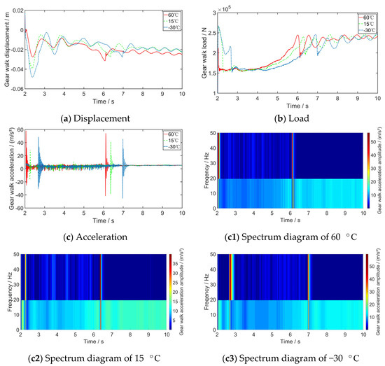
Figure 11.
Effects of different ambient temperatures on gear walk.
The variation trends of gear walk displacement, acceleration, and load are the same under different ambient temperatures. The load of the gear walk rapidly decreased to a lower load level and remained unchanged, then it rapidly increased to a larger load level and began to change statically. When the braking system is first started, with the rapid change of the gear walk load, the displacement of the gear walk has a large vibration, and the acceleration of the gear walk also has a short-term high-frequency vibration.
The displacement and acceleration of the gear walk also suddenly produced high-frequency vibration when the gear walk load rapidly increased, which ceased after 0.1 s and tended to be a stable vibration. The variation trend of the gear walk load is the same as the C/SiC brake disc friction coefficient variation trend. The friction characteristics of the C/SiC brake disc leads to the rapid increase of the gear walk load.
The vibration frequency under different ambient temperature is mainly 20 , the vibration amplitude below 20 is about 10 to 20 , and the vibration amplitude above 20 is about 5 to 10 . The variation trend of the gear walk load is the same as the C/SiC brake disc friction coefficient variation trend. The friction characteristics of the C/SiC brake disc lead to the rapid increase of the gear walk load.
With the increase of ambient temperature, the heat dissipating capacity of the brake disc shrinks, temperature changes the speed, the friction coefficient of the C/SiC brake disc and the gear walk displacement to reach stationary vibration occur earlier, and the gear walk acceleration amplitude increases. The C/SiC brake disc is more sensitive to the change of ambient temperature. Ambient temperature has a great effect on the gear walk displacement and load.
3.3. Brake Disc Material Effect on Gear Walk
The temperature variable friction characteristics of C/C brake discs and C/SiC brake discs are different. With the development of aviation materials, the materials used in landing gear brake discs gradually changed from C/C to C/SiC. Therefore, analyzing the different materials of brake discs’ variable friction characteristics and their effect on the gear walk is of great significance. A landing gear with brake discs of different materials will be used for simulation at an initial speed of 70 and an ambient temperature of 15 °C. The hydraulic anti-skid brake system controlled by the slip rate PID starts at 2 s. Brake disc materials’ effect on gear walk are shown in Figure 12, Figure 13 and Figure 14.
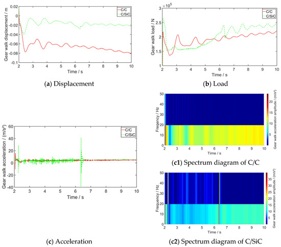
Figure 12.
Brake disc materials’ effect on gear walk.
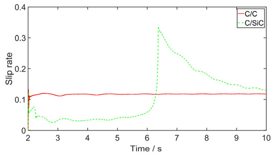
Figure 13.
Comparison of wheel slip rate.
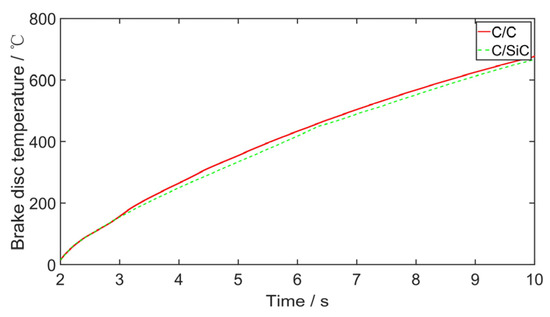
Figure 14.
Comparison of brake disc temperature.
Comparing a C/SiC brake disc with a C/C brake disc, the displacement amplitude and acceleration amplitude of the gear walk is larger. However, C/SiC brake discs have a “negative slope” phenomenon, which makes the displacement, acceleration, and load of the gear walk fluctuate greatly. Therefore, the slip rate of a landing gear using C/SiC brake discs suddenly changes at 6 s, and the acceleration of the gear walk also suddenly changes at this moment. Following this sudden change, the slip rate will gradually adjust to the optimum slip rate. The variable friction characteristics of the C/SiC brake disc have a great effect on the control of the slip rate by the PID control law. The slip rate of a landing gear wheel using a C/C brake disc fluctuates around the optimum slip rate, and the braking efficiency is higher.
The vibration frequency of a C/C brake disc is typically 20 , the vibration amplitude below 20 is about 12 to 18 , and the vibration amplitude above 20 is about 2 to 7 . As the friction coefficient of a C/SiC brake disc changes greatly, the maximum vibration amplitude of acceleration and the corresponding vibration frequency are higher than that of C/C brake discs.
Combined with the analysis of the brake disc materials’ effect on gear walk in Table 2 and the information shown in Figure 3 and Figure 4, the friction coefficient of the C/C brake disc fluctuates between 0.39 and 0.4, while the friction coefficient of the C/SiC brake disc increases to about 0.52 in the middle and late stage. The brake pressure required by a C/SiC brake disc is smaller, and the specific heat capacity of C/SiC material is larger. Therefore, the temperature variation of the C/SiC brake disc is reduced by 1.49%, the amplitude of the gear walk displacement is increased by 51.08%, the amplitude of the gear walk acceleration is increased by 99.37%, and the amplitude of the gear walk load is increased by 59.11% compared with that of a C/C brake disc.
Table 2.
Effect analysis of brake disc materials.
Thus, the effect of the friction characteristics of brake discs made from different materials on the gear walk are different. The influence of the C/C brake disc’s friction coefficient on the temperature change is smaller, and the C/SiC brake disc’s friction coefficient with the temperature change is larger. The C/SiC brake discs have a great effect on the gear walk, especially on the amplitude of gear walk acceleration, which reached more than 99%. Attention should be paid to the effect of the friction characteristics of brake discs made from different materials upon gear walk.
4. Conclusions
A rigid–flexible coupling dynamic model of a two-wheel strut landing gear considering the friction characters of brake discs constructed from different materials is established in this paper. A co-simulation method is used for analysis. The brake discs’ friction characteristics under different materials and ambient temperatures and their resultant effect on gear walk are studied. The conclusions are drawn as below:
- 1.
- In the time domain simulation analysis of gear walk, there is a “negative slope” phenomenon between the C/SiC brake disc friction coefficient and the wheel speed. The friction coefficient changes greatly when the temperature is below 600 °C. This phenomenon has a great effect on the gear walk characteristics and the control effect of the slip rate PID brake control law. The friction coefficient of the C/C disc has little change, and the variable friction characteristic is stable. Attention should be paid to the effect of the friction characteristics of the brake disc on the accuracy of simulation results;
- 2.
- The variable friction characteristics of C/SiC are easily affected by ambient temperature. The occurrence time of the “negative slope” phenomenon will be affected by different ambient temperatures. The change of ambient temperature has a great influence on the displacement and load of gear walk;
- 3.
- A C/SiC brake disc can solve the defect of a C/C brake disc’s low friction coefficient to a certain extent, which requires less brake pressure to be provided by the hydraulic system in the braking process and saves on energy consumption. However, the problem of large braking torque fluctuation caused by the “negative slope” phenomenon will also exacerbate gear walk and affect the braking efficiency of aircraft.
Author Contributions
Conceptualization, X.W., H.N. and Q.Y.; methodology, Q.Y.; software, J.S. and S.Z.; validation, S.Z. and J.S.; formal analysis, S.Z. and Q.Y.; investigation, S.Z.; writing—original draft preparation, S.Z.; writing—review and editing, S.Z. and Q.Y.; supervision, Q.Y.; project administration, X.W. and H.N. All authors have read and agreed to the published version of the manuscript.
Funding
This research was funded by the China Postdoctoral Science Foundation Funded Project (No. 2021M691565), the Aeronautical Science Foundation of China (No. 202000410520002), the Fundamental Research Funds for the Central Universities (No. NT2021004), the Fund of Prospective Layout of Scientific Research for NUAA (Nanjing University of Aeronautics and Astronautics), the National Natural Science Foundation of China (No. 51905264), the National Defense Outstanding Youth Science Foundation (No. 2018-JCJQ-ZQ-053), and the Priority Academic Program Development of Jiangsu Higher Education Institutions.
Institutional Review Board Statement
Not applicable.
Informed Consent Statement
Not applicable.
Data Availability Statement
Not applicable.
Conflicts of Interest
The authors declare no conflict of interest.
References
- Enright, J.J. Laboratory Simulation of Landing Gear Pitch-Plane Dynamics. SAE Trans. 1985, 94, 857–866. [Google Scholar]
- Jiao, Z.; Wang, Z.; Sun, D.; Liu, X.; Shang, Y.; Wu, S. A novel aircraft anti-skid brake control method based on runway maximum friction tracking algorithm. Aerosp. Sci. Technol. 2021, 110, 106482. [Google Scholar] [CrossRef]
- Jiao, Z.; Bai, N.; Liu, J.; LI, Y.; Wang, Z.; Sun, D.; Qi, P.; Shang, Y. Aircraft anti-skid braking control technology: A review. Acta Aeronaut. et Astronaut. Sin. 2022, 43, 1–27. [Google Scholar] [CrossRef]
- Yang, X. Problem of Landing Gear Vibration Arisen from Wheel and Brake. China Civ. Aviat. 1995, 09, 27–28. [Google Scholar]
- Gualdi, S.; Morandini, M.; Ghiringhelli, G.L. Anti-skid induced aircraft landing gear instability. Aerosp. Sci. Technol. 2008, 12, 627–637. [Google Scholar] [CrossRef]
- D’Avico, L.; Tanelli, M.; Savaresi, S.M.; Airoldi, M.; Rapicano, G. A deceleration-based algorithm for anti-skid control of aircraft. IFAC-PapersOnLine 2017, 50, 14168–14173. [Google Scholar] [CrossRef]
- Balasubramanian, K.; Farhang, K. Gear Walk Instability Studies Using a Vibration Model of a Reduced Scale Landing Gear System. In Proceedings of the ASME 2002 International Design Engineering Technical Conferences and Computers and Information in Engineering Conference, Montreal, QC, Canada, 29 September–2 October 2002. [Google Scholar]
- Yin, Q.; Jiang, J.Z.; Neild, S.A.; Nie, H. Investigation of gear walk suppression while maintaining braking performance in a main landing gear. Aerosp. Sci. Technol. 2019, 91, 122–135. [Google Scholar] [CrossRef]
- Liao, D.; Jiao, Z.; Wang, Z.; Qi, P.; Liu, X. Vibration Analysis on Six-wheel Landing Gear Induced by Anti-skid Brake. In Proceedings of the 2021 IEEE International Conference on Electrical Engineering and Mechatronics Technology (ICEEMT), Qingdao, China, 2–4 July 2021. [Google Scholar]
- Khapane, P.D. Gear walk instability studies using flexible multibody dynamics simulation methods in SIMPACK. Aerosp. Sci. Technol. 2006, 10, 19–25. [Google Scholar] [CrossRef]
- Rovira, A.; Roda, A.; Lewis, R.; Marshall, M. Application of Fastsim with variable coefficient of friction using twin disc experimental measurements. Wear 2012, 274, 109–126. [Google Scholar] [CrossRef]
- Lee, N.-J.; Kang, C.-G. The effect of a variable disc pad friction coefficient for the mechanical brake system of a railway vehicle. PLoS ONE 2015, 10, e0135459. [Google Scholar] [CrossRef] [PubMed]
- Ehret, M. Identification of a dynamic friction model for railway disc brakes. Proc. Inst. Mech.Eng. Part F J. Rail Rapid Transit 2021, 235, 1214–1224. [Google Scholar] [CrossRef]
- Liu, Z.; Xie, Y. Simulation study of aircraft brake system based on variable friction coefficient. Aeronaut. Sci. Technol. 2015, 26, 33–38. [Google Scholar]
- Krenkel, W.; Heidenreich, B.; Renz, R. C/C-SiC composites for advanced friction systems. Adv. Eng. Mater. 2002, 4, 427–436. [Google Scholar] [CrossRef]
- Zhang, Y.; Xu, Y.; Lou, J.; Zhang, L.; Cheng, L.; Chen, Z. Analysis of friction and wear properties of C/SiC composites. J. Aeronaut. Mater. 2005, 25, 49–54. [Google Scholar]
- Li, Z.; Xiao, P.; Zhang, B.-g.; Li, Y.; Lu, Y.-h. Preparation and tribological properties of C/C–SiC brake composites modified by in situ grown carbon nanofibers. Ceram. Int. 2015, 41, 11733–11740. [Google Scholar] [CrossRef]
- Fan, S.; Yang, C.; He, L.; Du, Y.; Krenkel, W.; Greil, P.; Travitzky, N. Progress of ceramic matrix composites brake materials for aircraft application. Rev. Adv. Mater. Sci. 2016, 44, 313–325. [Google Scholar]
- Ribbens, W.B.; Fredricks, R. A Sliding Mode Observer Based ABS for Aircraft and Land Vehicles. SAE Trans. 2003, 112, 223–230. [Google Scholar]
- Ryder, F.L.; Zaid, M. Landing-Gear Vibration Instability. J. Aerosp. Sci. 1959, 26, 303–309. [Google Scholar] [CrossRef]
- Lei, B.; Yi, M.; Xu, H. 3-D temperature field for C/C composite braking discs. Acta Mater. Compos. Sin. 2009, 26, 113–117. [Google Scholar] [CrossRef]
- Wu, Z. Study on Optimal Wear Control of Aircraft Landing Brake Based on Extended Life. Master’s Thesis, Civil Aviation University of China, Tianjin, China, 2018. [Google Scholar]
- Wang, J.; He, C. Determination of tire-runway friction coefficient. J.-Northwestern Polytech. Univ. 2000, 18, 569–571. [Google Scholar]
- Flugge, W.; Coale, C. The Influence of Wheel Spin-up on Landing-Gear Impact; National Advisory Committee for Aeronautics, NACA: Washington, DC, USA, 1954. [Google Scholar]


Publisher’s Note: MDPI stays neutral with regard to jurisdictional claims in published maps and institutional affiliations. |
© 2022 by the authors. Licensee MDPI, Basel, Switzerland. This article is an open access article distributed under the terms and conditions of the Creative Commons Attribution (CC BY) license (https://creativecommons.org/licenses/by/4.0/).