Abstract
Deep space missions are recently gaining increasing interest from space agencies and industry, their maximum exponent being the establishment of a permanent station in cis-lunar orbit within this decade. To that end, autonomous rendezvous and docking in multi-body dynamical environments have been defined as crucial technologies to expand and maintain human space activities beyond near Earth orbit. Based on analytical and numerical formulations of the relative dynamics in the Circular Restricted Three Body Problem (CR3BP), a family of optimal, linear and nonlinear, continuous and impulsive, guidance and control techniques are developed for the design of end-to-end rendezvous trajectories between co-orbiting spacecraft in this multi-body dynamical environment. To this end, several modern control techniques are effectively designed and adapted to this problem, with particular emphasis on the design of low cost rendezvous manoeuvres. Finally, the designed hybrid rendezvous strategies, combining both discrete and continuous control techniques, are effectively tested and validated under several start-to-end deep space testbench mission scenarios, where their performance is compared and quantitatively assessed with a set of performance indices.
1. Introduction
The recent proliferation of private and commercial ventures providing affordable access to low-Earth orbit and new crewed space vehicles [1], along with a renewed and increasing interest for deep space missions, not only from space agencies, but from the space industry and other actors, as highlighted in the Global Exploration Roadmap elaborated by the International Space Exploration Coordination Group [2,3], shows the necessity of advancing on new technologies to continue with this momentum and solve the challenges of the upcoming space missions currently being proposed. Visual inspection and extravehicular repair activities, spacecraft refueling and lifetime extension, active space debris removal, and resupply and other general on-orbit servicing missions are but a few of the most immediate applications requiring an increasing degree of autonomy and automation, with even more relevance in deep space missions. Along this line, the upcoming establishment of new crewed outposts in cislunar space within the next years, such as the Lunar Gateway, will require a continued service of resupply and regular crew transportation missions, that would benefit from autonomous capabilities for automated rendezvous, docking and other proximity operations in cislunar space, which have never been attempted to date, and thus still remain a major challenge for space exploration programs and missions beyond Earth orbit. Therefore, autonomous guidance, navigation and control capabilities have been defined as key enabling technologies to be developed in the coming years to support the expansion of human space activity beyond Earth orbit.
Libration Point Orbits (LPO) have been identified as ideal locations for the Lunar Gateway and other lunar and deep space exploration related activities. LPOs include periodic and quasi-periodic orbits, which posses highly interesting features due to their ability to maintain continuous communication with the Earth and their lesser station-keeping requirements. However, their inherent orbital instability yields relatively short time scales for divergence if the spacecraft abandons the nominal LPO or is subjected to perturbational acceleration sources, such as third body perturbations or solar radiation pressure. Therefore, a lot of effort has been devoted over the last three decades to the problem of trajectory control and station-keeping of LPO, initiated by the pioneer work of Farquhar [4,5]. Dynamical systems theory has been a fundamental role in the development of such control strategies. In this sense, early attempts exploited the periodic nature of these orbits, allowing for an approach based on Floquet’s theory, which led to the ‘Floquet Mode’ station-keeping strategy for LPOs, first proposed by Wiesel and Shelton [6] and Simo et al. [7], and later applied to the station-keeping of translunar LPOs [8]. Howell and Pernicka [9,10] proposed a new LPO station-keeping by adapting Dwivedi’s approach [11] to the LPO problem, leading to a strategy known as ‘Target Point’. Bai and Junkins [12] proposed a gradient-free computational approach based on a Modified Chebyshev-Picard Iteration method, which provided a simple and lightweight control structure. Hou et al. [13] proposed impulsive control strategies similar to the Floquet approach, which allowed to extend its applicability to the real Earth–Moon system by relying on quasi-periodic orbits referred to as dynamical substitutes. Folta et al. [14] extended the concept of the Target Point strategy to include optimality considerations by combination with a global search method and an orbit continuation method, resulting in a discrete control strategy which was successfully used for operational station-keeping in the ARTEMIS mission [15]. Recently Jin and Xu [16] proposed a modified strategy for selecting target points for LPO station-keeping to reduce manoeuvre costs in the real Earth-Moon system. Extensions to more complicated multi-body contexts have also been accomplished; Carletta et al. exploited the Hamiltonian formalism to develop a linear feedback compact station-keeping law in the Sun-Mars elliptic restricted four-body problem LPOs [17].
The aforementioned works proposed effective control strategies that relied heavily on dynamical systems theory and exploited the properties of intrinsic structures of the CR3BP, resulting in impulsive strategies; in contrast, they overlooked the plethora of techniques readily available in both classical and modern control theory, which can be effectively borrowed and adapted to the problem at hand. Along this line, Breakwell et al. [18] were the first to approach the LPO trajectory control problem from a classical control viewpoint by proposing a linear quadratic regulator for station-keeping of a translunar halo orbit. Control schemes of increasing complexity followed. Jones and Bishop [19] developed an output feedback guidance law using control theory. Scheeres and Vinh [20] developed a feedback control law based on the local eigenstructure of the LPO, which allowed for oscillatory motions in the center manifold. Luquette and Sanner [21] proposed an adaptive, nonlinear control for orbit maintenance in the vicinity of LPOs. Gurfil and Kasdin proposed a time-varying, continuous, linear quadratic control law, along with an internal disturbance model that rendered a robust disturbance rejection performance [22], and also investigated the early use of neural networks for tracking control and disturbance rejection in this context [23]. Marchand and Howell also developed continuous control strategies of increasing complexity based on linear and non-linear quadratic regulators and input/output feedback linearization [24], as well as through numerical solutions to the optimal control problem [25]. Infeld et al. [26] used Legendre pseudo-spectral methods to numerically solve the fuel-optimal, constrained, non-linear control problem. Kulkarni et al. [27] successfully adapted an approach to station-keeping control of LPOs. Nazari et al. [28] proposed three control strategies combining continuous LQR control and Floquet theory using periodic control gains; these relied, respectively, on an time-periodic infinite horizon LQR, a backstepping technique with time- invariant LQR, and a dead-band periodic-gain controller. Lian et al. [29] investigated the use of discrete-time sliding mode control and a discrete time linear quadratic regulator for station-keeping of real Earth–Moon LPO (i.e., with a complete Solar System model under a real ephemerides model), resulting in a discrete control suitable for impulsive manoeuvres. Ulybyshev [30] approached the station-keeping problem as an optimization problem, considering pseudoimpulses for discretized orbital segments, thus transforming the station-keeping problem into a large-scale linear programming form, resulting in a long-term station-keeping strategy for quasi-periodic LOPs in the full ephemerides model. Using a simple linear extended state observer, Narula and Biggs [31] extended an LQR control scheme to enable continued tracking in the event of thruster failure and the presence of disturbances; they also demonstrated that in combination with a sliding mode or an adaptive control, asymptotic tracking could be achieved. Peng et al. [32] demonstrated the robust maintenance of multi-revolution halo orbits in an elliptic restricted three-body problem using a receding horizon control strategy solved by an indirect Radau pseudo-spectral method. Qi and de Ruiter [33] extended the use of backstepping controllers for station-keeping of LPOs under practical navigational and executional constraints, a real ephemerides model and solar radiation pressure.
Héritier and Howell [34] looked into harnessing the natural, multi-body dynamics to minimize the drift of the unstable relative dynamics. Along this line, Xu, Liang and Fu [35] proposed a Hamiltonian structure-preserving control for LPO, which they successfully extended to the bi-circular four-body problem (i.e., time-periodic dynamics), and later to time-dependent dynamics, such as the relative orbital motion along low-energy transfer trajectories in the CR3BP [36], a path also investigated by Cheng et al. [37]. Jung and Kim [38] also proposed a switching Hamiltonian structure-preserving control. Other currently ongoing research includes Elliott and Bosanac [39,40], who are looking into LPO station-keeping controllers based on an alternative set of geometric coordinates, Bonasera, Bosanac et al. [41,42], who are looking into machine learning approaches to the LPO station-keeping problem, in particular with reinforcement learning, and Gao et al. [43], who are investigating high-order dynamical systems approaches for low-thrust station-keeping of LPOs. A thorough and extensive survey on LPO station-keeping strategies was presented by Shirobokov et al. [44], although it is unfortunately already outdated given the continued developments carried out in these research lines in recent years. Also, despite all these publications have focused on the trajectory control around LPOs, it is worth noting that a few publications have also looked into the general problem of relative orbital motion in the CR3BP, not necessarily bound to the vicinity of equilibrium points [45,46].
Traditional techniques for stability analysis and classical control build on linearization about a reference trajectory, which by extension leads to the problem of close proximity relative orbital motion and formation flight around a LPO. This immediately drew attention to multi-spacecraft formations and applications to interferometry missions and other distributed spacecraft architectures; in fact, many of the aforementioned bibliographic references revolve around such applications. In contrast, the problem of orbital rendezvous between two co-orbital spacecraft within the CR3BP framework seems to have drawn very little attention until recent years. Gerding [47] was the first to consider rendezvous in a CR3BP environment, by proposing a simple, two-impulse rendezvous strategy based on the linearized motion around a LPO. Jones and Bishop [48,49] derived a targeting law for the terminal phase rendezvous, loosely equivalent to the rendezvous application of Hill’s equations in the two-body problem, and constructed a Kalman-based rendezvous navigation filter to supply the targeting law with the chaser vehicle state information. Canalias and Masdemont [50] developed a methodology for the rendezvous of satellites on a Lissajous orbit using the effective phases plane together with a linear approach. However, it was not until well within the last decade that rendezvous in non-Keplerian environments become a topic of renewed interest upon studies related to the Lunar Gateway placement on a LPO. Mand [51] investigated simple, impulsive close-rendezvous targeting strategies adapting the line-of-sight corridor and the line-of-sight glide notions, of common use in Keplerian rendezvous. Ueda and Murakami [52] investigated into optimum guidance strategies based on free-drift dynamics, by following safe approach trajectories along invariant manifolds and into safe injection points for rendezvous in an Earth-Moon Halo orbit. Along this line, Sato et al. [53] proposed two different strategies for rendezvous on an Earth-Moon halo orbit by phasing along the orbit: one where the chaser approaches the target from behind along the orbit, similarly to a rendezvous in a low Earth orbit, and a second one utilizing an homoclinic intersection between an unstable manifold that departs from the halo orbit towards the Moon, where it connects to a stable manifold returning to the halo orbit, thus allowing an increased launch window and flexibility for mission design, and the capability to adjust the time of arrival to the halo orbit with a lower propellant usage. A similar approach, based on finding connecting manifolds on Poincaré maps, was proposed by Lizy-Destrez [54]. Murakami et al. [55] further investigated into the problems and requirements regarding guidance, navigation, and control for a rendezvous scenario in an Earth–Moon halo.
From 2015 onward, the spotlight was put into other types of LPO, such as Direct Retrograde Orbits (DRO) and Near-Rectilinear Halo Orbits (NRHO), once these were pointed out to be potentially better locations for the Lunar Gateway. Thus, Murakami and Yamanaka [56] proposed a three-impulse transfer from LEO to various phase points in a certain DRO, including a retrograde, powered lunar gravity assist. Ueda et al. [57] used standard, impulsive strategies to target an arbitrary relative position in halo, DRO and NRHO. Lizy-Destrez [58] provided a safety analysis for close approach rendezvous into a NRHO, and Davis et al. [59] looked into navigation accuracies and noise effects applied to various station-keeping strategies for NRHO, as well as examining the ability to absorb missed burns, construct phasing manoeuvres and conduct rendezvous and proximity operations. On a follow up work, Lizy-Destrez et al. [60] presented methods and results related to strategies for far and close rendezvous, and compared different linear and nonlinear models for cislunar relative motion; in particular, three- and four-impulse strategies are reviewed for the far-range rendezvous, and for the close-range renzdezvous, key concepts and several impulsive, targeting strategies available in the literature are reviewed. Blazquez et al. [61] looked at the far rendezvous approaches for NRHO and passively safe drift trajectories under a real ephemerides model, employing multiple-shooting and adaptive receding-horizon targeting algorithms, and more recently, Khoury and Howell [62] also looked into solutions to rendezvous and space loitering problems on NRHO and DRO type orbits. Bucchioni, in a series of works, focused on GNC for phasing and rendezvous under 6 DoF models [63,64,65].
It is a staggering realization though, that all the aforementioned rendezvous strategies and targeting methods are either impulsive strategies based on exploiting invariant manifolds or impulsive strategies for the close-range based on different flavours of linearized motion. Despite the vast literature dedicated to continuous-thrust station-keeping and formation flight control around LPOs, our literature review only revealed a handful of publications that proposed a continuous control for rendezvous under non-Keplerian dynamics; in particular, Ulybyshev et al. [66] presented an optimal method for the low-thrust rendezvous trajectory design in the vicinity of a lunar orbit under full ephemerides model by adapting their LPO station-keeping strategy based on pseudoimpulses distributed along discretized orbital segments, yielding a fully numerical, linear programming problem [30]. Sanchez et al. have successfully proposed both, impulsive and continuous MPC schemes for constrained, robust close-range docking in NHRO scenarios [67], while using a costly dynamics formulation based on a Local Vertical Local Horizontal reference frame. Another interesting contribution is the work by Colagrossi et al. [68], who studied the rendezvous and coupling in non-Keplerian orbits accounting for the orbit-attitude coupling and flexible modes of the structure of a very large space station, and more recently have also employed vision-based state navigation techniques for complete attitude-orbital state estimation and control [69]. Therefore, we found it surprising that, despite the wealth of literature devoted to the investigation of continuous-thrust LPO station-keeping and formation flight strategies built upon the classical and modern control theory, with the only exceptions of Refs. [66,67,68,69], to the best of our knowledge, none of the reviewed continuous controllers has been investigated nor adapted for analysis of rendezvous trajectories at LPOs. It was precisely this realization that served as motivation for the present work. Therefore, the main contributions of this manuscript are summarized in the following paragraph.
This work firstly revisits both analytical and numerical approaches to the problem of relative motion in the CR3BP; in particular: (1) the analytical linearization of motion around LPO is approached distinctively from other literature sources, exploiting the natural dynamics for near-libration points scenarios; resulting in a linear time-invariant (LTI) relative motion model to be exploited for GNC; and (2) a highly accurate numerical calculation scheme is presented for the relative motion in the CR3BP based on Encke’s method. Based on the developed analytical framework, a family of optimal, linear and nonlinear, impulsive and continuous set of control and guidance techniques are reviewed and developed to exploit the multi-body context and its intrinsic structures for far-range rendezvous and proximity operations in the CR3BP. Firstly, the optimal constrained rendezvous problem in the form of Bolza is introduced, and several guidance techniques are developed for successful optimal relative trajectory design. Both classical impulsive and continuous strategies, such as the LQR/SDRE or the two-impulse rendezvous scheme, are reviewed and compared in LPO missions. However, our work introduces the possibility of exploiting the presented low-cost LTI relative motion models for direct linear control synthesis, independent of the target motion. Secondly, two novel rendezvous techniques are presented: a numerical impulsive planning algorithm is designed based on classical launcher staging theory, yielding a recursive solution for the optimal thrusting directions. Moreover, the Augmented Lagrangian Iterative LQR (AL-iLQR) is formulated for our CR3BP rendezvous problem, for both continuous and impulsive missions. Thirdly, all presented guidance techniques are hybridized with inner compensator loops, implemented through Model Predictive Control and first-order Sliding Mode Control, to provide robust performance against uncertainties and unmodelled dynamics. Finally, the validation of the proposed dynamical models and the developed rendezvous techniques are exhibited in two realistic simulation scenarios for the James Webb Telescope and the future Lunar Gateway.
The remainder of this manuscript is organized as follows. In Section 2, both the absolute and relative dynamics in the CR3BP are briefly revisited, and novel approaches to both the precise numerical integration of the relative dynamics and the linearization of relative motion are introduced. Some preliminaries on Control Theory are also highlighted. Section 3 and Section 4 poses the general optimal rendezvous problem and comprises the design of several guidance techniques for general rendezvous trajectory planning between spacecraft in co-orbital motion. Both continuous and impulsive guidance algorithms are either revisited or presented, and a comparison between these techniques is also provided using specific performance indices. Section 5 effectively combines the proposed guidance cores with several modern, robust, continuous and impulsive controllers for general reference tracking of optimal rendezvous trajectories and again, performance analysis is accomplished for the overall guidance and control loop. In Section 6 all the trajectory design and control techniques presented in this paper are tested and validated upon two real-case mission scenarios, where these techniques are effectively employed and combined. Finally, Section 7 summarizes the main conclusions of this work.
2. Relative Dynamics in the Circular Restricted Three-Body Problem
2.1. Definitions and Governing Equations
The governing equations of motion considered in this study are framed within the Circular Restricted Three-Body Problem (CR3BP), where two celestial bodies of masses are considered, hereafter referred to as primaries, which revolve around their common barycenter under their mutual gravitation, thus describing a circular motion; a third body, i.e., a spacecraft, is considered with a comparatively negligeable mass , such that its motion is driven by the gravitational interaction with the primaries, whereas the primaries are not affected by the presence of the spacecraft. The motion of the spacecraft is naturally studied in a rotating, synodic frame , such that the primaries occupy fixed positions in the axis, the axis is set perpendicular to the orbital plane of the primaries (along the angular momentum of the system), and the axis completes a dextral frame. The unit vectors are defined, respectively, along each of the coordinate axes of the synodic frame. This is illustrated in Figure 1, which depicts the definition of the synodic frame with respect to the inertial frame . The latter is arbitrarily defined to be aligned with at the reference epoch , while other options are obviously available.
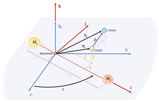
Figure 1.
Relative orbital motion in the CR3BP.
It is customary to use dimensionless coordinates, such that the distance between the primaries is used as characteristic length, the orbital period of the primaries around their common barycenter is taken as characteristic time, and the masses of the primaries are referred to the total mass of the system. In these dimensionless coordinates, the primaries revolve at one radian per unit of dimensionless time, the reduced mass of can be defined as
and the primaries are set at a unit length apart from each other, so their positions vectors (which are constant in synodic frame coordinates) can be conveniently written as
Under the aforementioned assumptions, the motion of the spacecraft is governed by the following second-order ordinal differential equation
where is the dimensionless angular velocity vector of the synodic frame with respect to the inertial frame , is the dimensionless spacecraft position vector as measured by an observer in the synodic frame, and the overhead dot () indicates derivatives with respect to the non-dimensional time.
In the following, the relative motion between two spacecraft, termed as target and chaser (following the usual nomenclature), will be addressed in the CR3BP framework. To this end, let us consider not one, but two spacecraft modeled as point masses, whose mutual gravity interaction is neglected. The target spacecraft is assumed to be cooperative and passive (i.e., with no orbital manoeuvring capabilities), and its orbit to be accurately known.
Let vectors and denote the position of the target and chaser spacecraft, respectively, so their relative position vector is defined as . Differentiating twice with respect to time and including the appropriate inertial terms, the following governing equations are obtained:
where are the synodic frame coordinates of the relative position vector , are the synodic frame coordinates of the target spacecraft position vector , and the control acceleration has been introduced for future concerns. Equation (2) can be compactly referred to as the following first-order, control-affine nonlinear system
The relative motion model is closed assuming the target spacecraft ephemerides are known.
The State Transition Matrix (STM), , can also be computed from the variational equations stemming from Equation (2). Both the flow’s stability and stroboscopic map are available from the propagation of the STM of the system along a reference trajectory, which satisfies
with J the Jacobian of the general dynamics vector field . For LTI dynamical systems, , the STM is explicitly given by
where the exp operator denotes matrix exponential.
2.2. Encke’s Formulation of the CR3BP Relative Dynamics
The lack of an analytical solution to the CR3BP enforces the necessity of numerical propagation. However, Equation (2) require some caution when evaluating their right-hand side: the order of magnitude difference between and yields a truncation error which quickly demises the integration process, specially in close proximity operations scenarios. Following [70,71], an Encke’s formulation [72] of the dynamics vector field can be derived and introduced for multi-body dynamics, which is better suited from the numerical viewpoint:
with
Integrating the latter set of equations provides the synodic frame coordinates of the relative position vector . This approach is used as the backbone computational integration algorithm in this work, yielding the same dynamics as Equation (2) while providing enhanced numerical accuracy with respect to the true chaser motion solution. This form of the dynamics is also leveraged in the integration of the STM, which benefit from the enhanced numerical properties of the scheme.
For demonstration purposes, a numerical test between the propagators (using either Newton’s or Encke’s formulation) is presented in Figure 2 for a standard halo orbit of out-of-plane amplitude of 20,000 . The performance comparison between the two addresses the -norm absolute error between the double-precision relative state vector, integrated in use of Equations (2) and (3), with respect to a quadruple precision baseline, obtained through integration of Equations (2) with maximum relative and absolute tolerances. The enhanced numerical performance and stability of the novel Encke’s propagator is clear when compared to the classical Newtonian results, showing an enhancement of an order of magnitude in terms of numerical precision all over the considered integration span.
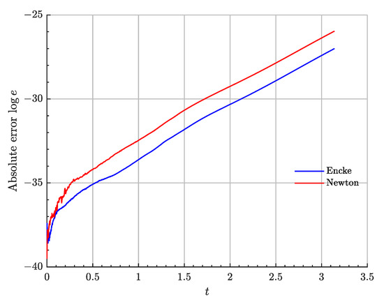
Figure 2.
Integration error for the different relative dynamics formulations.
2.3. Linearized Models
In relative orbital motion it is customary to employ linearization techniques for approximating the dynamics in the neighborhood of the target spacecraft. Retaining up to first order terms in Equation (2) yields the Rendezvous Linear Model (RLM) [45,52,62], which can be compactly expressed in matrix form as:
where and denotes 3-dimensional null and identity matrices, respectively; the Coriolis acceleration term reads
and the Hessian matrix can be computed as
where the operator ⊗ denotes the dyadic product, are unit vectors pointing from the i-th primary to the target spacecraft
and are coefficients defined as
Note that the Rendezvous Linear Model is time-dependent, since the matrix depends on the target spacecraft location . Consequently, the stability of the model cannot be easily assessed, as the eigenvalues of the system matrix depend explicitly on the target spacecraft ephemerides.
While the original RLM model was derived as a linearization of the true relative dynamics around the target position vector, in this work we introduce the Relative Libration Linear Model (RLLM), which considers relative motion near the collinear libration points, assuming both the target and chaser spacecraft to be on an LPO. In such cases, is expected to become constant or (quasi-)periodic, respectively. In fact, after linearization, can be shown to read [73,74]
The fundamental frequency is recognized to be that introduced by Richardson, which depends on the libration point both spacecraft orbit, as defined in [75]. As it can be seen, the relative dynamics are therefore uncoupled from the exact chaser’s and target’s trajectories while inheriting the absolute dynamics phase space solution structures [74], providing an LTI relative dynamics model (RLLM-LTI), which may be useful in the design of classical linear control schemes.
2.4. Discrete and Controlled Dynamics
In the design of the guidance and control schemes the following form of the state flow, as given by Lagrange’s formula, will be usually leveraged
The first term of the right hand side is the homogeneous solution of the dynamics, given by the discrete mapping of the initial conditions to the epoch of interest t. Such discrete mapping is defined by the STM of the system, which can be numerically computed by integrating the variational equations along with a reference phase space trajectory . The convolutional, integral term constitutes the effect of the control action through the control input matrix B on the dynamics.
In astrodynamics applications, a discrete or impulsive manoeuvre sequence is usually conceived as a feasible, natural and straightforward control strategy. Particularising Lagrange’s formula for such action plan yields the following result
where the is Dirac’s delta generalized function. Introducing the time shifting property of the STM, the above result can be further expanded as
Some of the guidance techniques developed in Section 4 are founded on the premise of discrete dynamics. The classical results just presented can be used to construct a discrete map for a given discrete time sequence , under the action of both continuous and discrete control functions. For the latter case,
For continuous control inputs, some assumption shall be made with respect to the control action between time steps . This work employs a zero-order hold between instants and a first order Euler quadrature for the STM exponential, giving
3. Optimal Impulsive Guidance
The following section introduces several impulsive optimal guidance schemes for general proximity operations trajectory design. Moreover, the different techniques are compared against each other under a homing and rendezvous mission scenario.
The use of the term guidance in this context applies to the computation of both a reference state trajectory and control input . The guidance core will be then cascaded with an inner control or compensator loop, whose techniques are described in Section 5.
All guidance laws presented in this work can be either used online, in feedback manner, or computed offline and explicitly stored and regressed over an independent variable of interest, such as time, for online GNC purposes.
3.1. The Rendezvous Problem
In practice, most proximity operations and regular orbital control activities can be formulated as an optimal rendezvous problem, involving either two real spacecraft or the relative dynamics of a given vehicle with respect to some virtual object. This treatment motivates the formulation of the Rendezvous Problem.
The Rendezvous Problem is formally stated as a path-constrained two-boundary value problem, where a finite control law is sought such that the chaser spacecraft follows a relative motion that takes it to the origin of the relative phase space after some finite time of flight , thus mathematically fulfilling the Rendezvous Condition, namely . Hence, the Rendezvous Problem can be compactly stated as the following optimal control problem in the form of Bolza:
where , saturate the control function p-norm and is an appropriate model of the relative dynamics.
3.2. Surrogate Optimization and Backward-Forward Sweep
The majority of the guidance techniques presented in this section benefit from surrogate relative motion models when addressing the Rendezvous Problem, mainly based on an appropriate linearization of true nonlinear dynamics and the corresponding STM . Moreover, the computation of is at most, when not build upon an analytical model, numerically integrated through the linear variational equations along the flow .
Therefore, any control policy computed under such dynamics is not guaranteed to rendezvous the relative state vector under the true nonlinear field. In general, some form of feedback is needed to successively refined and to comply with the nonlinear relative motion dynamics. This is achieved through iterating a backward-forward pass or sweep structure until convergence:
- Along the backward pass, the guidance control policy is solved for under an appropriate approximation of the true nonlinear dynamics, such as the discrete map given by the current estimate of the STM .
- In the forward pass or rollout, the converged input is used to re-integrate to higher accuracy and refine the state flow , dictating the approximate dynamics in the backward process (for example, the estimate of the STM).For offline guidance, both direct iteration or Newton-Rhapson differential correctors [76] are used to re-evaluate the STM along the flow and update the nominal control sequence . Online guidance is based on the Model Predictive Control (MPC) approach described in Section 5, in which the true nonlinearities and uncertainties unmodelled in the surrogate guidance model are accommodated through a time-receding horizon scheme under the true plant dynamics.
3.3. Two-Impulse Guidance
Given the linearized dynamics in Equation (8), proximity operations trajectory design can be determined through planning the impulsive control sequence with respect to some optimality policy, usually penalizing both integral loss functions of the control effort and error to the desired state .
Although a single impulse suffices to nullify the relative range to target after some time of flight , two impulses () are mandatory to fully regulate the 6-dimensional relative state (rendezvous the two spacecraft). Thus, the linear two-impulse (TI) rendezvous scheme, widely used within the context of Keplerian motion since the 60s [77] and suggested in previous investigations [51], is here explicitly adapted to the context of the CR3BP for comparison purposes against more complex strategies. Moreover, compared to previous literature, our scheme can profit from direct LTI dynamics (lower computational cost in the integration process) and a more numerically accurate integration process, as introduced in Section 2.
The backward pass of the TI scheme is given by evaluating Equation (8) with a first impulse at , , and a second impulse at , , which provides the final state vector. Enforcing the Rendezvous Condition and solving for the impulses yields the following solution:
where the subscripts of indicate the corresponding partitions of the STM following the usual notation.
The forward pass may be implemented both using MPC or classical differential correctors. In the latter case, as already stated, these expressions are solved iteratively for the current estimate of and its effect under the nonlinear vector field to re-estimate the STM, which depends on the initial conditions, so it is an implicit function of . Under the MPC paradigm [78], for an N-horizon time span, TI problems are solved, and the problem’s true dynamics accommodated through the complete horizon.
3.4. Multi-Impulse Guidance
A multi-impulse (MI) rendezvous allows for greater flexibility in the design of the relative trajectory, as accuracy-in-the-execution constraints may be relaxed and navigation errors can be accommodated in any of the manoeuvres to be performed.
For the MI backward pass, Equation (8) evaluated at can be compactly expressed in matrix form as
with matrices and defined as
with and denoting horizontal and vertical concatenation, respectively. For non-LPO missions, a similar approach may be found in [46] exploiting the duality of linear input-output systems.
Enforcing the Rendezvous Condition and solving for yields
where the operator denotes the Moore-Penrose pseudoinverse [79]. This solution also introduces an -norm penalty on the impulses vector as a general fuel consumption metric [80]. Moreover, an appropriate decomposition of provides the solution for less general rendezvous problems, such as position waypoint targeting.
The overall performance and convergence of the associated differential corrector is compromised by the initial conditions, the final time of flight, , and the selected execution times for the burns, , triggering the effect of neglected nonlinearities in the problem’s dynamics.
In any case, and as for the TI technique, Equation (12) needs to be solved iteratively in the backward-forward structure. In this case, the most appropriate feedback formulation is the Newton-Rhapson method due to the sparsity of the expected impulses.
3.5. Optimal Multi-Impulsive Guidance
Further developing the multi-impulsive scheme naturally leads into its optimal formulation (Opt-MI), in which the N execution times and their associated burns are optimally computed. The selected loss function to be minimized here is the total propellant consumption or, equivalently, the aggregated of the N impulses, for which the -norm is most fitting [80]. This yields a Linear Programming minimization problem in which, under a linearized model of the dynamics, the component-wise constrained magnitude of the N burns can be determined for a rendezvous with the target object at a prescribed time of flight , namely:
The use of the synodic reference frame together with Encke’s formulation of the dynamic vector field ensures a cheaper and numerically better-behaved STM propagation when compared to previous work [67]; in addition, the use of the -norm as a proxy for fuel consumption and its associated LP optimization problem allows the online use of the algorithm without major computational expenses.
As already mentioned, the solver shall be embedded in some form of feedback loop to converge the control impulses sequence under the true nonlinear dynamics, through an iterative refinement of both the input and the STM . In this case, the MPC paradigm in Section 5 may be used as forward pass, due to the lack of an exact form of an appropriate differential corrector to solve the problem under iteration.
3.6. Multi-Impulsive Staging Guidance
Despite the benefits of multi-impulsive schemes, as already seen, additional criteria or assumptions are needed to determine the impulses executions times , on which the performance of the controller is totally dependent on. While the previous algorithm develops an online cost-effective optimal rendezvous problem solver, its formulation depends on the -norm proxy for fuel consumption, which, in some cases, may not be representative of the true mass dynamics of the mission.
Inspired by classical launcher staging mass optimization, the novel Multi-Impulsive Staging Guidance (MISG) core aims to solve the following constrained optimization problem during the backward pass:
The cost function is selected as a proxy of control effort and fuel consumption and to ease further algebra. As for the rest of this derivation, the relative weights are assumed to be equal and unitary, . is the desired relative state at the final time of flight . The complete impulse sequence can be determined considering discrete dynamics, therefore eliminating the impulse times as explicit optimization variables. For a given time of flight and time grid , the problem is fully determined, so that for every time node in the grid, a (possibly null) optimal impulse is computed.
The necessary conditions for optimality are given by constructing an augmented Lagrangian function and computing its stationary point with respect to ,
resulting in the following equations for the variables
The Lagrange multiplier can be eliminated through the use of equations i and , reading the following recursive system
The final algebraic system to be explicitly solve is therefore
Equation (15) is suited for the MPC forward pass iteration, with applications in online feedback guidance. However, for offline cases, and by noting that the complete sequence is a function of the first impulse only , a Newton-Rhapson differential corrector scheme can be formulated to iteratively correct under each STM refinement iteration until convergence. For the latter case, Equation (15) can be further simplified as
where the sensitivity matrix G is defined as
G gives the Newton-Rhapson update step to through iterating the following result
If the sequence needs to be control-input bounded or constrained in any other manner, the associated inequality can be introduced in the cost function through additional slack variables , yielding
3.7. Impulsive Iterative Linear Quadratic Regulator
The last impulsive guidance scheme presented in this investigation is a novel application of the Augmented Lagrangian Iterative Linear Quadratic Regulator (AL-iLQR) for spacecraft rendezvous under LPO dynamics. The motivation and detailed derivation of the AL-iLQR may be found in Section 4, after presenting the classical Linear Quadratic Regulator (LQR) policy for continuous dynamics.
Our AL-iLQR paradigm aims to solve the discrete constrained optimization problem
where is a control authority bound and the inequality/equality set given by introduces general state constraints, such as Line-of-Sight restrictions [81]. The discrete dynamics given by the map represent the relative motion dynamical system in any of its forms.
The constrained problem is relaxed and solved as a series of unconstrained optimizations by appropriately augmenting J [82]
The method achieves a low-cost optimization of a quadratic proxy of the control effort and the final and integral rendezvous error in finite time, under discrete impulsive manoeuvres. It generalizes the LQR solution to nonlinear systems by iterating on the optimal control policy during the backward pass and updating the flow over the forward pass, as described later on. The significance of the penalizing matrix sequence and R may also be found in Section 4. Finally, it is trivial to augment the relative state to incorporate an integral penalty term, as discussed also in Section 4.
3.8. Performance of Impulsive Control Rendezvous Manoeuvres
In the following, the different impulsive guidance algorithms presented in this section are tested and compared using the complete nonlinear equations of relative motion in the CR3BP. To that end, a long-range example scenario is proposed where the target and chaser spacecraft are in two distinct northern halo orbits around the Earth-Moon , as depicted in Figure 3. The target spacecraft is located in a halo orbit of an out-of-plane amplitude of 20,140 ; the dimensionless time of flight to rendezvous was selected to be 0.6, corresponding to 2.67 days (this value is found to be the critical time for the given orbit ensuring the differential correction convergence). For the AL-iLQR, however, this value was modified to units or 14 days: despite seeming a relaxing constraint, it does promote control cost, as the number of impulses increases drastically. Additionally, and despite showing finite time convergence, the AL-iLQR benefits from longer time of flights, in which the true nonlinear dynamics can be optimized; for short time scales, the algorithms tends to overshoot the optimal solution. The dimensionless initial conditions for the target and the chaser spacecraft are, respectively:
corresponding to an initial relative range of 13,195 .
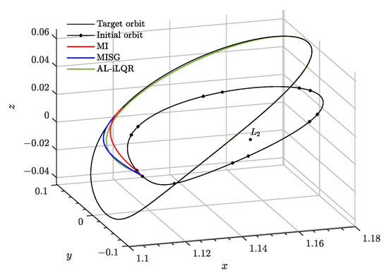
Figure 3.
Rendezvous trajectory in the absolute configuration space for the MI, MISG and AL-iLQR schemes.
Several considerations must be addressed regarding the configuration of the different guidance schemes:
- The STM is integrated along the reference state trajectory through the linear variational equations of Encke’s formulation of the relative dynamics, Equation (3). Despite being the most accurate, they are also the most expensive in terms of computational cost, providing a worst-case scenario for performance analysis. For the sake of demonstration and comparison, the TI algorithm is also employed in use of the RLLM analytical STM.
- For the sake of comparison, all state constraints are relaxed for all schemes, and the upper control bound is set to for the Opt-MI case (component-wise) and for the AL-iLQR. However, to nullify the final relative velocity, such bound is relaxed at the time of flight.
- For the multi-impulsive case, six burns were selected to be performed along the trajectory; we chose a randomly distributed set of values (given in Table 1 for the sake of reproducibility) to illustrate the intrinsic robustness of this algorithm, for which the impulse sequence is critical.
 Table 1. Set of prescribed, randomly distributed values used for the MI algorithm.
 - For the Opt-MI, MISG, impulses are planned every 1 time units. For the AL-iLQR, 5 nondimensional time units are used instead.
- All controllers are formulated as open-loop schemes, in which differential correctors suit better as forward passes. However, to address the clear performance difference against MPC, both the Opt-MI and MISG techniques are formulated using also the latter.
- Matrices Q and R in the AL-iLQR scheme are selected to be constant andMoreover, the initial estimation of the optimal flow is given by the coasting solution .
- No uncertainty is considered in the simulation, and remains to be introduced under the performance of the robust controllers in Section 5.
To quantitatively analyze the performance differences between controllers, we use as a proxy a series of performance indices related to the rendezvous error and the propellant consumption of the manoeuvre; these indices are defined in Appendix B. The performance indices for these techniques in the considered example are summarized in Table 2. Moreover, the minimum and maximum impulses norms (for those distinct to 0) are also displayed to quantitatively bound the feasibility of each algorithm.

Table 2.
Performance comparison for the impulsive guidance schemes.
All guidance schemes present really similar error performance, the MISG scheme showing slightly better results. The majority of the presented techniques also show similar computational cost, except precisely for the MISG algorithm, which, in both forms of the forward sweep, solves the optimal problem one order of magnitude slower. Interestingly, the use of the analytical RLLM STM rises the computational time of the TI algorithm when compared to direct numerical integration of the variational equations. This is explained by an increase in the number of iteration until convergence, from 4 to 15 in the RLLM case. However, provided that they show the same results, the analytical version of the algorithm is particularly suited for online calculations when compared to its integrated counterpart. Finally, regarding control cost, both the Opt-MI, MISG and AL-iLQR (despite showing an increase of impulses by a factor of 10) show similar performance, as they all are both optimally conceived and constructed. Interestingly, the TI and MI controllers show a much smaller control effort, deviating 18% and 50% from the nominal values. This is attributed to the sparsity of impulses in both algorithms, indicating that the selected number of impulses are closer to the optimal value [83,84,85]. For the other 3 controllers, the number of impulses is determined by the minimum time step considered in the discretization of the dynamics. However, for both the TI, MI and Opt-MI algorithms, the final impulse nullifying the relative velocity increases by a factor of nearly 5 when compared to the rest of controllers. Again, this is explained by the lack of optimality considerations founding the algorithms.
Figure 3 demonstrates the proposed rendezvous trajectories in the absolute configuration space, while Figure 4 displays the relative state evolution in time under the action of each controller. All of them are able to successfully drive the chaser to rendezvous the target spacecraft located in a different periodic orbit with a convergence error below 1, and differential corrections requiring less than 50 iterations to converge in the worst scenario. Finally, Figure 5 shows the evolution of the control impulse sequence for the optimal multi-impulsive controllers. The MISG algorithm can be shown to maintain bounded the control sequence all over the time span. Independently of the numerical solver in use, the algorithm shows similar control trends: first, the relative range is targeted at the initial stages, driving the sequence towards a coasting period, and then towards the end of the transfer, the action plan nullifies the relative velocity progressively. On the other hand, the AL-iLQR shows most control activity in the early stages of the transfer and then a nearly coasting phase, exploiting natural transport dynamics.
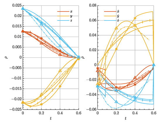
Figure 4.
Relative state evolution for the TI (solid), AL-iLQR (dashed), Opt-MI (*), MI (barred), MISG (triangled) strategies.
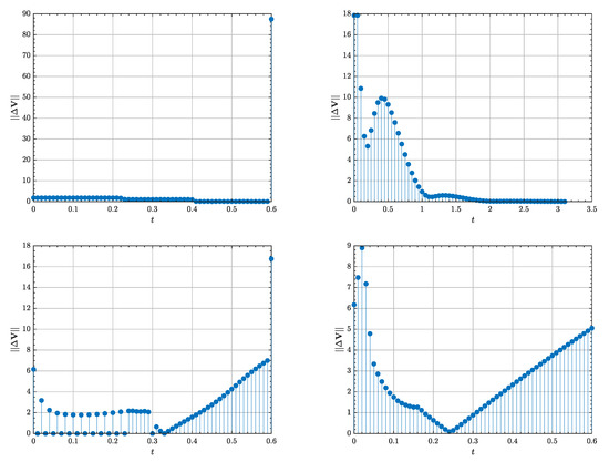
Figure 5.
Impulse sequence in for the Opt-MI/MPC (upper left), AL-iLQR (upper right), MISG/DC (lower left) and MISG/MPC (lower right) strategies.
The terminal phase of the rendezvous trajectory () is re-designed making use of the full constrained AL-iLQR, in which the chaser shall approach the docking port through a given safety corridor. Such constraint is introduced by
which models a cone-like constraint defined by the half-cone angle , together with an axial direction given by the unit vector . In this simulation, and the cone axis is selected to be , which is assumed to be aligned with the docking axis at the rendezvous time . Despite being nonlinear in the state , the constraint need not any redefinition and can be directly introduced in the AL-iLQR algorithm.
Figure 6 depicts the evolution of the relative angle between and in time. Again, convergence towards is noticeable. Finally, Table 3 compiles the major performance metrics of the algorithm, where no difference can be appreciated with respect to the unconstrained case, demonstrating the robustness and adaptability of the AL-iLQR technique when compared to the rest of the presented guidance schemes.
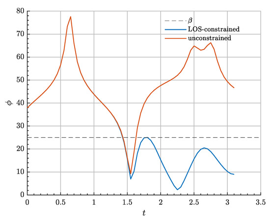
Figure 6.
Relative docking angle evolution for LOS-constrained and unconstrained rendezvous using AL-iLQR.

Table 3.
Performance metrics for the LOS-constrained AL-iLQR rendezvous.
4. Optimal Continuous Guidance
Continuous acceleration control schemes may also provide efficient rendezvous strategies and are intrinsically interesting for low-thrust propelled missions, where control cost and rendezvous efficiency constraints may be again imposed and emphasized. In this section, three such continuous acceleration controllers are presented. Previous results on the Linear Quadratic Regulator and State-Dependent Ricatti Equation (SDRE) guidance are discussed and combined with the new linear dynamical models presented, before introducing a novel AL-iLQR methodology for spacecraft rendezvous. All three techniques are suited for both online and offline guidance.
4.1. Linear Quadratic Regulator
Since the Rendezvous Condition is satisfied at the origin of the relative phase space (namely, the equilibrium point in Equation (2)), a Proportional-Integral-Derivative (PID) controller can be constructed to asymptotically drive the system to such state. Thus, the control acceleration can be defined as
where , and are, respectively, the proportional, derivative and integral gains. To introduce an integral penalty term, the relative state vector and dynamics Equation (5) are augmented as follows
Using the augmented state vector, an infinite horizon Linear Quadratic Regulator (LQR) can now be proposed [21,73], which provides the optimal control law, , by minimizing the following quadratic cost function
where matrices Q and R define the weights of the states and the control inputs, respectively. The optimal solution is then obtained as
where P is the solution of the following Algebraic Ricatti Equation for the infinite horizon case:
provided that and R are positive semidefinite and definite matrices, respectively, the pair is controllable and is observable. Once the Q and R matrices are appropriately selected, the optimal control law may be found to rendezvous the two spacecraft. Such selection may be addressed using pole placement arguments or using more advanced techniques, such as Genetic Algorithms, to trade-off asymptotic convergence and control expense. In general, the ratio Q to R defines the performance of the controller: the cost function J is a relative trade-off between nominal state error and control effort, and Q and R balance such compromise solution.
One important remark is that, since the LQR formulation relies on an LTI model, an operating point needs be defined for the target spacecraft, so that the linear system of Equation (19) is indeed time-invariant. In this sense, numerical experiments show that optimal performance is obtained when the model is evaluated at the target’s orbital state at the rendezvous time of flight. However, and compared to previous literature, this work exploits the novel RLLM as a natural LTI formulation for the LQR method, rendering the controller independent of the target’s motion from definition.
4.2. State Dependent Ricatti Equation Controller
Although the LQR controller formulation yields a successful scheme to rendezvous the two vehicles, the requirement to fix a prescribed operating point for the target spacecraft constrains its applicability and handicaps its performance. State Dependent Ricatti Equation (SDRE) controllers overcome this shortcoming by providing a time-varying generalization to the LQR formulation for general nonlinear vector fields of the type
in which a quadratic cost function analogue to Equation (20) can be defined, where matrices and no longer need to be constant, but can depend on the state vector, i.e., they are allowed to vary in the relative state space.
Upon linearization, under certain conditions [86] the dynamical system can be reduced to a state dependent linear model of the type
where the pair is assumed to be point-wise stabilizable. For the relative motion in the CR3BP, such a state dependent linear system arises from the point-wise linearization around the target spacecraft’s orbit, i.e., for points along the trajectory of the target spacecraft, as given by the RLM model in Equation (5). In that case, a SDRE controller can be straightforwardly designed by defining an augmented linear model analogue to Equation (19), only that and now depend on time implicitly through the target’s time law. Therefore, for prescribed matrices and , an optimal control law can be computed for the linearized problem upon solving the corresponding algebraic Ricatti equation, resulting in the control law:
The suboptimal policy can be shown to be stable and asymptotically regulate the relative augmneted state towards the Rendezvous Condition.
Detailed derivations and applications of the SDRE controller for optimal rendezvous can be found in [65,73], including available extended formulations for state-constrained rendezvous and proximity operations.
4.3. Iterative Linear Quadratic Regulator
The iterative Linear Quadratic Regulator (iLQR) is an optimal trajectory planning algorithm widely applied in robotics applications, and a variant of the classical Differential Dynamic Programming technique [87,88]. iLQR generalizes the classical optimal control LQR solution to nonlinear system through iterative first-oder linearization of the dynamics [89]. The main two formulations of the algorithm are found in [82,89]. The latter may be conceived as more general (as it is based on Bellman’s Principle of Optimality) and provides the framework to incorporate state constraints in the underlying optimization problem, with the so-called Augmented Lagrangian paradigm (AL-iLQR).
The following discussion is focused on the application of AL-iLQR for continuously controlled rendezvous trajectory planning, while it can be easily adapted to impulsive missions, as already discussed in Section 3.
Our AL-iLQR paradigm aims to solve the discrete constrained optimization problem
where is a control authority bound and the inequality accommodates general state constraints. Again, the relative motion dynamical system is represented by the discrete vector field . A discussion on the selection of the dynamical model within the AL-iLQR method can be found at the end of this section. Finally, a zeroth-order hold is assumed for the control action over time step , resulting in a piecewise control solution.
The constrained optimization problem is relaxed into an unconstrained version, to be solved iteratively until constraints are satisfied and the extremum control sequence is found. In the following, the set of p constraints are collapsed into the vector inequality .
Initially, an augmented Lagrangian cost function is constructed through appropriate penalty Lagrange multipliers terms
where are the constraints Lagrange multipliers and the quadratic penalty term is constructed upon the weight matrix , defined as
are user-defined hyperparameters to be optimized during the process. Therefore, the constrained problem has been transformed into the following unconstrained one
The solution to the original constrained problem is given by the iteration of the following sequence of steps
- Solve the unconstrained problem (23) using the iLQR technique, with fixed.
- Update the estimation of the Lagrange multipliers
- Update the penalty weights through the schedule
If feasible, the problem is considered solved when constraints are satisfied to a given tolerance and the unconstrained problem (23) is also optimally solved. Numerical details and enhancements to the method can be found in [82,87]. The convergence of the algorithm is also driven by an appropriate selection of the Q and R matrices: aside from determining the final optimal trade-off between control cost and rendezvous error, as in the classical LQR or SDRE, they also affect the positive definiteness of the action value Hessian, on which the algorithm’s convergence totally depends on.
At each iteration, the control law is updated through the sequence control and state deviation , given by
where the feedforward term is given by the Hessian and gradient of the cost function. State estimation on is achieved through the STM flow mapping, which can benefit from analytical models, such as the RLLM. The exact derivation and solving of Step I may be found in Appendix C [82], where the Hessian of the action value function can be seen to be given by an appropriate Gauss-Newton approximation. This lower-accuracy expansion, compared to its true 2-rank nature, is the main difference between iLQR and classical Differential Dynamic Programming, and, while it makes the former require more iterations to converge, it also diminishes the computation burden of the algorithm, making it suitable for online processing.
An iteration over Step I is finished with the forward pass, given by flow solution over the updated control action
J denotes the Jacobian of . Step I is assumed to converge whenever the difference between iterations in the cost function reaches some tolerance or a maximum number of iterations is exceeded.
As it may be noted, linearized dynamics are used in the recursion for the optimal flow variation under the effect of . Depending on the selection of the dynamics vector field , the exact form of will be distinct, either numerical or analytical, and the associated computational burden of the method will also increase or decrease during the forward pass. Moreover, the reached solution will be optimal for the model in use: if is the true CR3BP relative motion dynamics, the rendezvous trajectory design will already account for the problem’s nonlinearities, while other surrogate models (see Section 2) could also be used for further refinement within the inner robust control loop.
Finally, the method is in need of a first estimation of the optimal trajectory and control . Given the trajectory initial conditions , both the natural coasting solution () or any other guidance solution (such as that provided by the LQR) may be used as such initial guess.
4.4. Performance of Continuous Control Rendezvous Manoeuvres
In this section the previously described continuous guidance schemes will be compared upon each other in a test scenario based on an Earth-Moon Lyapunov orbit of an in-plane amplitude of = 10,000 , as depicted in Figure 7, for which the dimensionless initial conditions for the target spacecraf and the relative state are, respectively:
yielding an initial range of . The selected time of flight for the mission is in nondimensional units, or 28 days. However, to exploit the finite time convergence of the AL-iLQR scheme and show its superior performance, its final time of flight is restricted to 8.91 days in this latter case, in non-dimensional units.
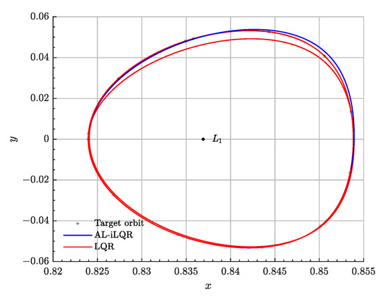
Figure 7.
Rendezvous trajectory in the absolute configuration space for the AL-iLQR and LQR (RLLM) controllers.
Regarding the setup of the rendezvous example, the following considerations shall be addressed:
- All guidance techniques make use of an augmented state vector , to include an integral penalty term within the appropriate cost function.
- Again, no uncertainty or process noise is considered in the simulations.
- The LQR trajectory was designed in use of the LTI Relative Libration Linear Model in Equation (6) instead of that in Equation (5) to exploit its intrinsic time-invariant nature. A comparison against the RLM model is also addressed. SDRE guidance is based on the RLM model, Equation (5), while the AL-iLQR outputs an optimal state flow for the true nonlinear dynamics.
- For the AL-iLQR technique, a nondimensional time units zeroth-order hold was used, and numerical integration performed through MCPI, as described in Appendix A. Discrete linearization of the true nonlinear relative dynamics is achieved by numerical propagating the STM through Encke’s linear variational equations at the forward pass, providing the worst-case scenario in terms of computational performance. Finally, the initial estimation of the optimal flow is given by the open loop LQR guidance solution.
- LQR and SDRE schemes are defined by the following constant, penalty weight matrices Q and Rwhile for the AL-iLQR, after some trial and error, these are selected to be
Figure 8 shows the evolution of the chaser’s relative state vector as a function of time for the three showcased controllers, and Table 4 summarizes for each controller the performance indices as defined in Appendix B, including maximum and minimum acceleration, and , respectively. Additionally, Figure 9 shows the evolution in time of the norm of the control acceleration as a proxy to the real performance of the aforementioned schemes.
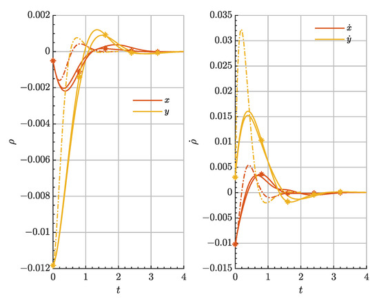
Figure 8.
Relative state evolution for the LQR (solid), SDRE (*) and AL-iLQR (dashed) controllers.

Table 4.
Performance comparison for the continuous guidance schemes.
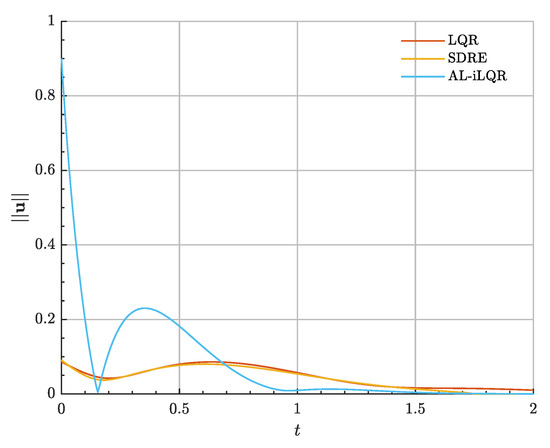
Figure 9.
Control acceleration in for the LQR, SDRE and AL-iLQR controllers.
On the basis of such results, several conclusions may be drawn. First, little gain is achieved by means of exploiting time-varying linearizations of the relative dynamics when compared to trivial LTI models such as the RLLM (which, to best of our knowledge, had not been explicitly used for rendezvous before). Difference between the LQR and SDRE controllers are minimum in terms of both the state error and the associated control cost. The only exception accounts for the inclusion of state domain constraints within the optimal quadratic problem, in which the SDRE formulation is needed [65]. Secondly, the AL-iLQR paradigm shows similar error performance to that of infinite horizon controllers but in finite time (the time of flight is reduced by 70%) despite the increase in the total control cost (as expected for a discrete horizon formulation). For the AL-iLQR case, this increase is counterbalanced by the possibility of explicitly imposing control authority bounds (and general constraints), a major concern within continuous control applications when compared to total budgets. In this example, the resulting control acceleration is in the order of . However, the algorithm lacks numerical robustness, specially when selecting both the Q and R matrices sequences, due to its sensitivity to the positive-definiteness of the action value gradient and Hessian. In terms of the computational cost, both the LQR and AL-iLQR provide similar performance (in the order of seconds) while the SDRE and its need to solve the Ricatti equation over the state trajectory are much more expensive (order of minutes).
A similar study was conducted on the rendezvous mission scenario presented in Section 3 to confirm such conclusions, under the very same setup. Results are shown in Table 5. First, in terms of computational cost, both the LQR and AL-iLQR algorithms show the same order of magnitude as in the previous case, contrary to the SDRE controller, whose performance augments. This may be explained by better numerical conditioning of the optimal control when compared to the previous mission scenario, in which the out-of-plane dynamics are numerically ill-behaved. Error metrics are similar for all three controllers despite the different handled time scales. Cost performance shows the greatest differences, remarkably for the LQR: in this scenario, in which dynamics play a greater role, the selection of the LQR determines its performance, still profiting the use of LTI models (on which its optimal solutions builds) when compared to the use of linearisation points. Again, the AL-iLQR is the most expensive in average due to its discrete time convergence properties and the initial control overshoot given by the selected Q-R matrices ratio. Figure 10 and Figure 11 show the relative state evolution of this second rendezvous test and the associated control acceleration for the three guidance techniques, highlighting the discrete/asymptotic capabilities of the three techniques.

Table 5.
Performance comparison for the continuous guidance schemes.
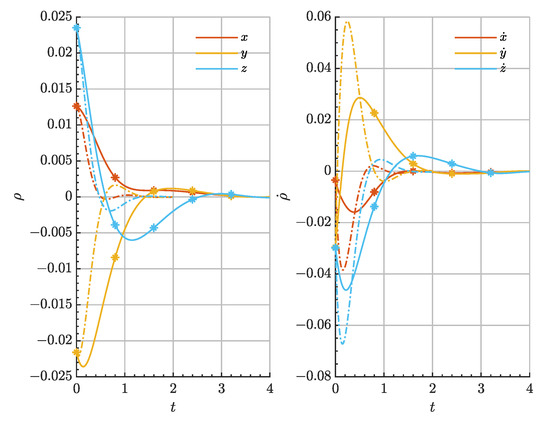
Figure 10.
Relative state evolution for the SDRE (*) and AL-iLQR (dashed) controllers for the halo transfer mission scenario.
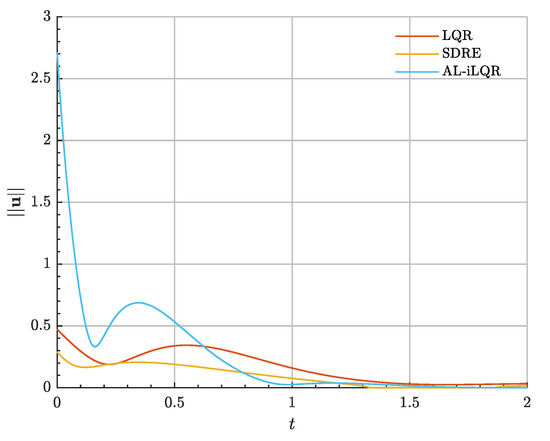
Figure 11.
Control acceleration in for the LQR, SDRE and AL-iLQR controllers for the halo transfer mission scenario.
5. Modern Optimal Control
After discussing optimal trajectory planning and guidance, two controllers, for both impulsive and continuous missions, are discussed for robust reference tracking, control and disturbance rejection. Their cascaded combination with the presented optimal guidance techniques is also first achieved now.
Observe that in practice, all guidance techniques may be indeed employed as feedback controllers (i.e., for reference tracking), if the designed of the reference trajectory is achieved by any other mean. However, classical linear controllers, such as the LQR or SDRE, usually lack the robustness and generality offered by the proposed modern control approaches.
5.1. Model Predictive Control
Modern Predictive Control (MPC) is an optimal control technique based on iterative optimization, introduced in the late 1980s [78,90], and since then abundant literature may be found for rendezvous a proximity operations [81,91,92,93,94], while only recently has been applied in multi-body scenarios [67,73].
In the MPC paradigm, an optimal guidance problem is solved for a given time horizon under discrete dynamics, and as a result, both a state trajectory and control action policy are returned. The controller only executes the action at the initial time , and, after the plant natural rollout one time step ahead, the optimization problem is run again with the time horizon receded . Such time prediction horizon is assumed in this work to be externally constrained by, for example, mission analysis considerations.
As already, discussed, all presented impulsive guidance techniques are subject to be adapted as the optimization core of an MPC-controlled process, where linear dynamics are used as an optimization surrogate model. The true nonlinearities of the CR3BP relative motion, uncertainty and process noise are compensated along the time receding horizon through iterative optimization. Of particular relevance is to note the synergy between the AL-iLQR technique and an MPC iterative process [87], which, as the rest of combinations and to the best of our knowledge, has not been addressed before for rendezvous purposes. In such scheme, at each time step, the former is used for motion planning in a fast and robust way, while the upper MPC iteration accommodates non-modelled effects in the optimization model. Not only the combination MPC/AL-iLQR is promoted for impulsive guidance and control, but it can also be employed for low-thrust missions given the piecewise nature of the continuous iLQR solution.
5.2. Sliding Mode Control
Sliding Mode Control (SMC) is one of the most widely used variable structure controllers, developed by Emelyanov et al. in the late 1950s [95]. An SMC relies on discontinuous piecewise functions to provide global Lyapunov stability properties to the controlled plant by forcing the dynamical system to slide on a given state space manifold in which first-order dynamics are imposed [96].
Consider the dynamical system of Equation (21), where and may not be exactly known, but upper-bounded by continuous operators all over the state space. If the relative error is measured with respect to a given state space reference trajectory, , then the sliding hypersurface is defined by
where represents a Hurwitz scalar. In this work is chosen, which yields a first-order SMC control law.
Any tracking problem is therefore equivalent to stabilizing the system dynamics on , which is also equivalent to imposing the Lyapunov’s Direct Method condition Once the sliding manifold is defined, a global exponentially stabilizing behaviour may be obtained from the following equivalent control law:
provided exists. Also, the Lyapunov constraint is imposed outside the sliding surface using the following discontinuous reaching control function:
where denotes the Euclidean norm, is strictly positive, , and is the boundary layer for the saturation operator , which prevents the system from chattering across the sliding surface:
Hence, the final control law is given by (t).
For the rendezvous problem at hand and for a prescribed desired guidance trajectory for the chaser to follow, , the SMC control law simplifies to:
where is given by any appropriate model of the relative dynamics.
The parameters completely define the controller’s performance, where:
- is the characteristic time of the reduced first order exponential dynamics on such state subspace.
- and determine the controller across the sliding surface, with direct implication on chattering or weak attractive properties of the surface.
- The boundary layer defines the control bandwidth and the precision to which saturation of the control law is necessary to reach the sliding surface.
This set of parameters can be optimized for the performance of the controller. However, the non-smooth nature of the SMC prevents the use of gradient-descent based techniques. In this work, Genetic Algorithms [97] have been used to heuristically explore this parameter search space and select the optimal set minimizing the following convex multi-objective cost function over a set of typical guidance trajectories of interest
where is a constant gain to account for the rendezvous error in the minimization problem.
6. Applications and Testbench Mission Scenarios
This section presents two simulation scenarios to illustrate the use of the manoeuvre design schemes introduced in the preceding sections, and for the purpose of validation and benchmarking.
In the following test cases, all numerical integrations were performed by means of Encke’s formulation for the relative dynamics using a variable-step, variable-order Adams-Bashforth-Moulton predictor-corrector solver of orders 1 to 13 with absolute and relative integration tolerances set to and , respectively, as implemented in Matlab 2021b’s function ode113 [98].
The time discretization for the simulations output was set to nondimensional time units, which corresponds to 1.68 h in the Earth-Moon system and 8.76 days in the Sun-Earth system; consecutive maneuvers were also constrained not to be executed in less than such time interval.
Navigation uncertainty in the state estimation was modeled as a zero-mean normal multivariate distribution , with diagonal covariance matrix for the relative position space and for velocity. Moreover, impulsive control actions are -bounded by , which corresponds to in the Earth-Moon system and for the Sun-Earth case. Continuous acceleration is restricted to be smaller than unless otherwise specified. Finally, process noise is added as a white noise disturbance, where .
6.1. Servicing a Solar Observatory
Solar and telescope missions have played a fundamental role in both our understanding of the Solar System and our surrounding space environment, as well as the development of modern Orbital Mechanics. As a matter of fact, both the Solar and Heliospheric Observatory and Genesis spacecraft were the very first to demonstrate and use the Three-Body Problem dynamical solutions as a basis for their missions. Libration points provide ideal locations for celestial observation mission too, due to their illumination conditions and uninterrupted communication with the Earth. Hence, for the James Webb Space Telescope (JWST), launched in December 2021, a Sun-Earth halo orbit with an orbital period of 6 months was selected as its nominal orbit. The JWST and its potential visual-inspection and repair necessities throughout its mission lifetime provide the first validation scenario for the proposed GNC techniques. A nominal northern halo orbit has been selected to be representative of that of the real mission.
The chaser spacecraft is intended to perform a formation flight around the target spacecraft (JWST) and, if needed, rendezvous with it for repair or maintenance activities. The mission will then finish with an exploration of the Sun-Earth interior realm.
The proposed mission timeline for this fictional JWST servicing spacecraft is summarized in Table 6, and the different mission phases and their associated control cost estimates are listed in Table 7. The spacecraft is assumed to be equipped with chemical propulsion and an electric thruster for relative formation flying. Additionally, simulations only reproduce proximity operations activities, while the transfer phase from a low-Earth orbit to the target halo orbit range is not considered here; it may be achieved by means of the stable manifold of the orbit, just as the nominal transfer trajectory for the JWST was planned, with potentially null associated control cost [99].

Table 6.
Phases timeline for the JWST servicing mission.

Table 7.
Phase metrics for the JWST servicing mission.
The proximity operations mission starts after nominal loitering halo orbit insertion of the chaser vehicle, into a distinct halo orbit to that of the target. This initial long range approach considers acquiring the relative range for the start of the formation flying. The initial conditions of the target and the chaser relative state at the halo insertion time are
which corresponds to an initial relative range of 623,520 km.
The guidance and control scheme used in this phase corresponds to the combination of the MPC controller with an optimal iLQR technique. The time horizon considered is , with impulses every nondimensional time units (corrections every 2.90 days). The time of flight of the phase is set therefore to units. Moreover, any state constraint is relaxed in this initial phase. Finally, after an heuristic trial and error process, the discrete AL-iLQR algorithm is defined by the following penalty matrices
The performance of the algorithm gives a reduction of 98% of the initial relative range, as shown in Figure 12, where the relative state evolution of chaser spacecraft can be analysed. Figure 13 depicts the control input evolution in time during this initial phase.
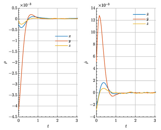
Figure 12.
Evolution of the relative state vector components for the JWST servicing spacecraft during the long-range homing.
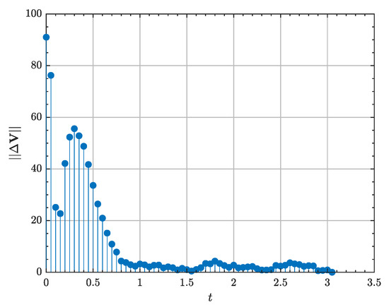
Figure 13.
Control input in for the JWST servicing spacecraft during the long-range homing.
Once the relative formation flying range is acquired, offline LQR guidance (in use of the integral-augmented RLLM) is combined with the SMC controller to position the chaser at to the JWST and maintain such relative distance for two months, by converting the relative formation flying problem into a virtual time-invariant rendezvous problem under an appropriate change of variables. The total time of flight is , formation flying starting at from phase start. The initial conditions of this phase are given by
The LQR is defined by the weight matrices
while the SMC, after tuning, is defined by the parameter set
Offline guidance refers to the regression of the LQR reference state trajectory as a function of time, in this case through an appropriate low-order projection in Chebyshev polynomials .
The relative state evolution of chaser spacecraft can be analysed in Figure 14. The needed low-thrust acceleration is displayed in Figure 15.
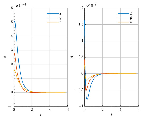
Figure 14.
Evolution of the relative state vector components for the JWST servicing spacecraft during the low-thrust approach.
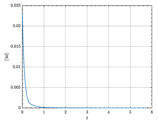
Figure 15.
Control input in for the JWST servicing spacecraft during the low-thrust approach.
After 243.33 days of visual inspection and formation flying, the chaser spacecraft is planned to rendezvous with the target vehicle using the combined MPC-MISG core described in Section 3. The phase considers a time horizon of impulses in nondimensional time units. The phase initial state for both the target and relative spacecraft is given by
The final (purely numerical) relative error between vehicles is of , which, in position space, corresponds to , thus successfully achieving the rendezvous of the two spacecraft. Figure 16 shows the relative state evolution during this final close-range rendezvous phase, while Figure 17 depicts the needed impulses to accomplish the rendezvous.
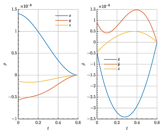
Figure 16.
Evolution of the relative state vector components for the JWST servicing spacecraft during the final close-range rendezvous.
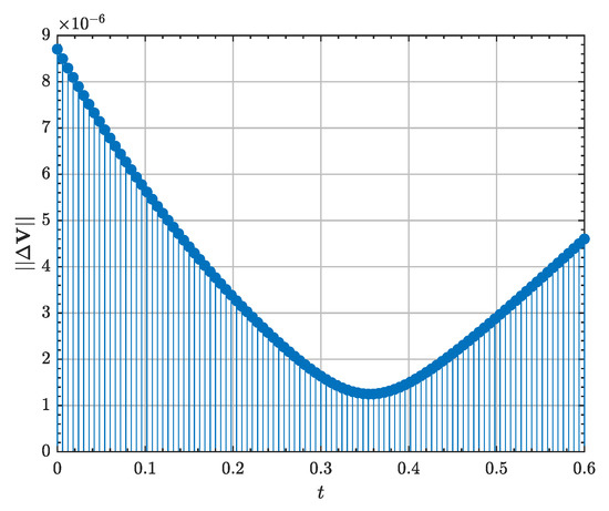
Figure 17.
Control input in for the JWST servicing spacecraft during the final close-range rendezvous.
The trajectory of the proposed JWST servicing mission for the complete mission timeline is illustrated in Figure 18.
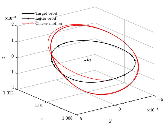
Figure 18.
Trajectory of the JWST servicing spacecraft for the complete mission timeline.
Thus, the proposed solution leads to affordable rendezvous maneuvers and control strategies, where the majority of the control budget is allocated to perform the relative formation flying phase, which is by far the longest in time and the most demanding in high-frequency actuation. Moreover, despite the associated budget, the phase is completed using bounded continuous propulsion, for which direct requirements are less stringent thanks to their higher specific impulse. The rest of the manoeuvres are negligible in cost, while successfully completing all phases. The proposed guidance and control architecture is therefore demonstrated for the mission.
6.2. Rendezvous in a near Rectilinear Halo Orbit
For the past decade, deep space missions have gained increasing attention from the space industry. In order to ease such missions, a lunar orbit station is planned to be established within this decade, known as the Lunar Gateway [2,3], which will serve as a communication hub and short-term habitation module to support human return to the Moon and as a staging point for these deep space missions. Thanks to their station keeping long term stability, nearly uninterrupted communication with Earth and eclipse-avoidance properties, Near Rectilinear Halo Orbits (NRHO) have been selected as the major candidate for the Gateway nominal trajectory; these orbits are highly eccentric trajectories, nearly normal to the orbital plane of the Earth-Moon system. The NRHO family can be found in both and southern halo sets, at the closest side to the Moon; although they are an intrinsic solution to the CR3BP, they also persist under ephemerides models. NRHOs provide easy access to the lunar surface, as well as to the Earth, by means of their stable and unstable manifolds.
The Lunar Gateway and their supply and re-fueling necessities will provide the second validation mission scenario that we shall consider: for crew replacement and life support resupply purposes, a chaser spacecraft is tasked to rendezvous with the Gateway station after being inserted into its nominal NRHO orbit, located at the point in the Earth-Moon system.
The proposed mission schedule for this Lunar Gateway resupply mission is summarized in Table 8, and the different mission phases and their associated control cost estimates as listed in Table 9.

Table 8.
Phases timeline for the Gateway re-supply mission.

Table 9.
Phase metrics for the Gateway resupply mission.
Again, the transfer trajectory from Earth may be designed based on the globalized NHRO stable manifold with potentially null associated control cost [99]. Such design is not considered in this simulation. Instead, to propose a demanding mission scenario, the chaser spacecraft is first inserted into a northern halo orbit of out-of-plane amplitude of = 20,000 to demonstrate the capabilities of the proposed GNC architecture even in extreme trajectory design cases. Moreover, this initial halo orbit may serve as a loitering circuit for a complete multi-spacecraft re-supply chain. The initial conditions of the Gateway station (the target) and the relative state after insertion into the loitering orbit are:
which corresponds to an initial relative range of 112,967 km.
The transfer shall be accomplished in less than 14 days or , given it will be performed using low-thrust propulsion. The continuous SDRE algorithm is used to construct an optimal low-thrust trajectory between the two LPO in close-loop. The algorithm is defined by the following Q and R matrices
Figure 19 and Figure 20 demonstrates the low-thrust transfer and insertion into the nominal target halo orbit in the absolute and relative phase space, respectively. Moreover, Figure 21 shows the needed control acceleration to accomplish the transfer. A lower control authority bound exists to escape the gravitational well of the Moon, which is found to be . The optimal transfer trajectory reduces the initial relative range by 99.99%.
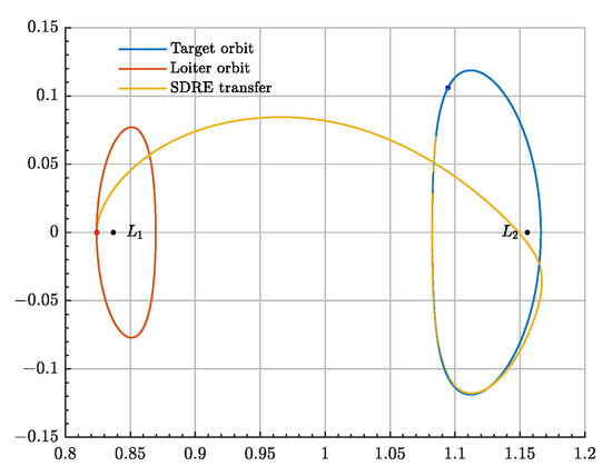
Figure 19.
Absolute trajectory for the Lunar Gateway resupply mission during the long-range rendezvous.
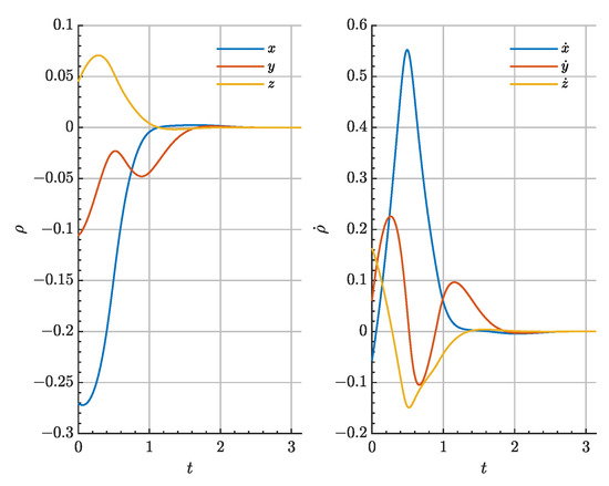
Figure 20.
Relative state evolution for the Lunar Gateway resupply mission during the long-range rendezvous.
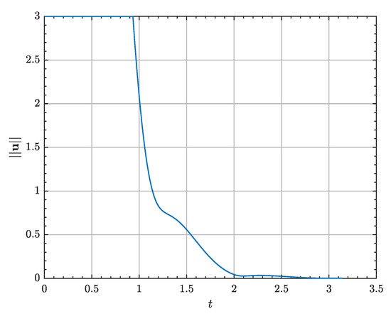
Figure 21.
Control input in for the Lunar Gateway resupply mission during the long-range rendezvous.
The second phase comprises close-range rendezvous and re-supply of the Gateway after a total time of flight of nondimensional time units or 5.57 days. The selected GNC architecture to fulfill such task is the combination of the MPC scheme with the Opt-MI guidance algorithm, with impulses every 1.07 h. The initial conditions of the phase are
Figure 22 depicts the relative state evolution during this second phase. High-frequency impulsive actuation is clearly noticed, also given in Figure 23. The minimum required control actuation is . The final rendezvous error is of , completing the rendezvous and docking.
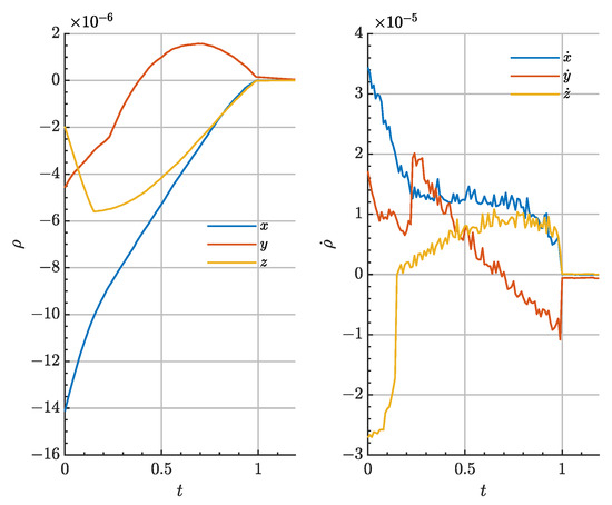
Figure 22.
Relative state evolution for the Lunar Gateway resupply mission during the close-range rendezvous.
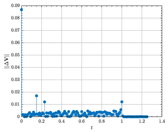
Figure 23.
Control input in for the Lunar Gateway resupply mission during the close-range rendezvous.
Before finishing the mission with a retrieval of the chaser spacecraft to the nearbies, a formation flying demonstration is performed around the Lunar Gateway at a relative range of ∼, where the chaser vehicle performs a Lissajous relative orbit-like of amplitudes , and frequencies , . The SMC controller tracks the desired state evolution for 21 days or . The initial conditions of the phase are
Figure 24 shows the relative state evolution during this last phase, where the periodic variation of both the position and velocity is noticeable, as well as the transitory secular departure of the relative state from the rendezvous condition to the nominal formation flying relative range. The associated control acceleration is given in Figure 25.
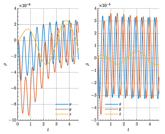
Figure 24.
Relative state evolution for the Lunar Gateway resupply mission during formation flying.
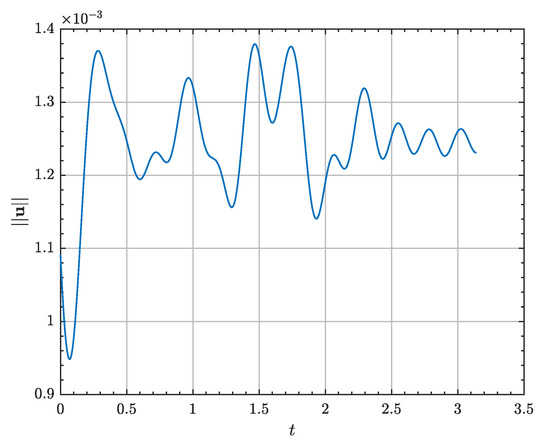
Figure 25.
Control input in for the Lunar Gateway resupply mission during formation flying.
Again, the majority of the required budget is allocated to the low-thrust long-range rendezvous, the contributions of the other two phases being negligible in comparison. Moreover, with an appropriate design of the loitering orbit, this control effort may be even null if heteroclinic connections between the two halo orbits are exploited. Interestingly, a relatively complex formation flying configuration is accomplished nearly for free.
7. Conclusions
The problem of relative orbital motion within the CR3BP framework is tackled in this work. First, a framework for the relative dynamics in the CR3BP is presented: a new set of relations is derived for the development of control schemes based on linearized dynamics, including a novel LTI relative motion model, and a scheme based on Encke’s formulation is presented for the accurate numerical calculation of the relative motion. Afterwards, these tools are utilized for the design of rendezvous manoeuvres between spacecraft in relative motion within the CR3BP dynamical model. To this end, several control and guidance approaches of increasing complexity and performance are investigated and either successfully adapted or specifically designed to relative motion applications and proximity operations in the framework of CR3BP. These approaches enable the design of efficient and affordable (in terms of budget) rendezvous trajectories between spacecraft in neighboring trajectories. These techniques cover a variety of approaches, ranging from impulsive manoeuvres (two-impulse manoeuvres, multi-impulse manoeuvres, optimal -norm multi-impulsive sequence planning algorithms), to continuous thrust manoeuvres (based on Linear Quadratic Regulators, State Dependent Ricatti Equation, Augmented Lagrangian Iterative Linear Quadratic Regulator). Moreover, the presented guidance techniques are effectively combined with modern control strategies for robust and optimal guidance reference tracking (Model Predictive Control for impulsive control inputs and Sliding Mode Control for acceleration-based actuation).
These trajectory design techniques have been successfully validated through application to several mission scenarios, which showcase a good performance (based on a series of proposed performance indices) and flexibility, both for mission design as well as for autonomous proximity operations. However, the design of a complete GNC architecture is still to be accomplished, where navigational aspects, beyond the scope of this work, play a major role. Improvements to the presented algorithms, both for further exploiting the problem’s intrinsic dynamical structures and extending them to rendezvous-related activities, remain as an open line of research for future work.
Author Contributions
Conceptualization, S.C.d.V., H.U., P.S.-L., R.G.-R. and A.K.S.; methodology, S.C.d.V., H.U. and P.S.-L.; writing—original draft preparation, S.C.d.V.; writing—review and editing, H.U., P.S.-L., R.G.-R. and A.K.S. All authors have read and agreed to the published version of the manuscript.
Funding
This research was funded by the Spanish State Research Agency and the European Regional Development Fund through the research grant PID2020-112576GB-C22 (AEI/ERDF, UE).
Data Availability Statement
Not applicable.
Acknowledgments
S.C.d.V., H.U. and P.S.-L. wish to acknowledge the Spanish State Research Agency and the European Regional Development Fund for their support through the research grant PID2020-112576GB-C22 (AEI/ERDF, UE). The Ministry of Education, Culture, Sports, Science and Technology (MEXT) of the Japanese government supported R.G.-R. under its program of scholarships for graduate school students.
Conflicts of Interest
The authors declare no conflict of interest.
Abbreviations
The following abbreviations are used in this manuscript:
| CR3BP | Circular Restricted Three-Body Problem |
| GNC | Guidance, Navigation and Control |
| iLQR | Iterative Linear Quadratic Regulator |
| JWST | James Webb Space Telescope |
| LOS | Line of Sight |
| LP | Linear Programming |
| LPO | Libration Point Orbit |
| LQR | Linear Quadratic Regulator |
| LTI | Linear Time Invariant |
| LTP | Linear Time Periodic |
| MI | Multi-Impulse |
| MISG | Multi-Impulsive Staging Guidance |
| MCPI | Modified Chebyshev Picard Iterations |
| MPC | Model Predictive Control |
| Opt-MI | Optimal Multi-Impulse |
| RLM | Rendezvous Linear Model |
| RLLM | Relative Libration Linear Model |
| SDRE | State Dependent Ricatti Equation |
| SMC | Sliding Mode Control |
| STM | State Transition Matrix |
| TI | Two-Impulse |
Appendix A. Numerical Integration
Throughout this investigation, two numerical integrators are predominantly used and are here described.
General integration of the relative and absolute motion dynamical systems is achieved through a variable-step, variable-order Adams-Bashforth-Moulton predictor-corrector solver of orders 1 to 13. The latter is is used to form the error estimate and the function does local extrapolation to advance the integration at order 13. Such integrator has been employed as commercially implemented in Matlab 2021b [98].
Additionally, the iLQR guidance core benefits from a Modified Chebyshev-Picard Iterations (MCPI) integrator, as formulated in the seminar work of Bai [12]. The high-accuracy MCPI scheme allows to integrate the nonlinear, controlled relative vector field without explicit regression of the control law with respect to an independent variable, thus allowing for enhanced numerical precision.
Consider the first-order differential dynamical system
where is the control input. The solution of the above system is given by the quadrature
Given an initial estimation of , the MCPI approximates the solution as a Chebyshev polynomial series of order N, evaluated over the Chebyshev nodes
where T is the Chebyshev polynomial matrix evaluated over the Chebyshev nodes and W is an appropriate weight matrix (see [12] for details). Vector is the coordinates of in the Chebyshev functional space.
To comply with the differential vector field , such approximation is updated following an iterative procedure described now
- Compute the nonlinear vectorfield evaluated at the Chebyshev nodes
- Compute the updated polynomial coefficientswhere is a function of the initial conditions and is appropriately defined in [12].
- Update the state approximation
Iterations continue until some convergence criteria is met.
Appendix B. Performance Indices
Different performance indices are defined and used to compare the proposed guidance and control schemes to achieve rendezvous and proximity operations. These are based on proxies that are regularly used in Control Theory to assess general control performance, defined both in terms of the rendezvous error in time and the needed control effort made to accomplish such state.
In particular, the Integral of the Absolute Error (IAE) and the Integral of the Square of the Error (ISE) are well-known performance indices to address the performance of a given control input action as a function of the final system relative error; for this study, we define these indices as the following integral loss functions:
Propellant consumption can be directly quantified using the Euclidean norms of the integral and -distances of the control law over the time of flight , thus defining the following performance indices:
Finally, the equivalent finite burn is given by the following integral:
In addition, the computational cost of each algorithm has been quantified by means of the mean computational time taken to solve the problem in particular over 25 repetitions each. Simulations have been performed in Matlab using an 11th Gen Intel(R) Core(TM) i7-1165G7 @ 2.80 GHz with 15.7 GB of RAM.
Appendix C. AL-iLQR Formulation, Hessian and Gradient Approximations
The following Appendix details the mathematical formulation of the AL-iLQR scheme, and the exact form of the gradient and Hessian operators within the AL-iLQR optimal problem. Recovering its general formulation
attention is now drawn to the Step I if the iLQR scheme, solving the unconstrained problem. The backward pass first starts decomposing the cost function into a terminal and running cost
Using Bellman’s Principle of Optimality and realising the recursive structure in J, a cost-to-go and action value functions, respectively, are defined
To optimize the action sequence , deviations from the true optimal solution are considered by a second-order expansion of
At the final step N, is completely defined
denote partial derivatives with respect to the vector . To derive a recursive relationship between and , the second-order expansion of M around the optimal solution is leveraged
The optimal control sequence deviation is therefore given by
Finally, the Gauss-Newton approximation of the Hessian of M and its gradient yield the following exact expressions
where and are the gradient and Hessian of the cost-to-go function . Precisely, the backward pass is closed with the recursions for ,
Matrices A and B are the linearization of with respect to and
References
- Weinzierl, M. Space, the Final Economic Frontier. J. Econ. Perspect. 2018, 32, 173–192. [Google Scholar] [CrossRef]
- International Space Exploration Coordination Group. Global Exploration Roadmap; Technical Report; NASA: Washington, DC, USA, 2018. [Google Scholar]
- International Space Exploration Coordination Group. Global Exploration Roadmap Supplement; Technical Report; NASA: Washington, DC, USA, 2020. [Google Scholar]
- Farquhar, R. The Control and Use of Libration-Point Satellites; Technical Report; NASA: Greenbelt, MD, USA, 1970. [Google Scholar]
- Farquhar, R.; Muhonen, D.; Newman, C.; Heubergerg, H. Trajectories and Orbital Maneuvers for the First Libration-Point Satellite. J. Guid. Control 1980, 3, 549–554. [Google Scholar] [CrossRef]
- Wiesel, W.; Shelton, W. Modal control of an unstable periodic orbit. J. Astronaut. Sci. 1983, 31, 63–76. [Google Scholar]
- Simó, C.; Gómez, G.; Llibre, J.; Martínez, R.; Rodríguez, J. On the optimal station keeping control of halo orbits. Acta Astronaut. 1987, 15, 391–397. [Google Scholar] [CrossRef]
- Gómez, G.; Howell, K.; Masdemont, J.; Simó, C. Station-Keeping Strategies For Translunar Libration Point Orbits. In Proceedings of the Advances in the Astronautical Sciences, Greenbelt, MD, USA, 11–15 May 1998; Volume 99. [Google Scholar]
- Howell, K.; Pernicka, H. Station-keeping method for libration point trajectories. J. Guid. Control. Dyn. 1993, 16, 151–159. [Google Scholar] [CrossRef]
- Howell, K.C.; Gordon, S.C. Orbit Determination Error Analysis and a Station-keeping Strategy for Sun-Earth L1 Libration Point Orbits. J. Astronaut. Sci. 1994, 42, 207–228. [Google Scholar]
- Dwivedi, N.P. Deterministic Optimal Maneuver Strategy for Multi-Target Missions. J. Optim. Theory Appl. 1975, 17, 133–153. [Google Scholar] [CrossRef]
- Bai, X.; Junkins, J.L. Modified Chebyshev-Picard Iteration Methods for Station-Keeping of Translunar Halo Orbits. Math. Probl. Eng. 2012, 2012, 1–18. [Google Scholar] [CrossRef]
- Hou, X.; Liu, L.; Tang, J. Station-keeping of small amplitude motions around the collinear libration point in the real Earth–Moon system. Adv. Space Res. 2011, 47, 1127–1134. [Google Scholar] [CrossRef]
- Folta, D.; Pavlak, T.; Howell, K.; Woodard, M.; Woodfork, M.A. Stationkeeping of Lissajous Trajectories in the Earth-Moon System with Applications to ARTEMIS. Adv. Astronaut. Sci. 2010, 136, AAS 10-113. [Google Scholar]
- Folta, D.C.; Pavlak, T.A.; Haapala, A.F.; Howell, K.C.; Woodard, M.A. Earth–Moon libration point orbit stationkeeping: Theory, modeling, and operations. Acta Astronaut. 2014, 94, 421–433. [Google Scholar] [CrossRef]
- Jin, Y.; Xu, B. A Modified Targeting Strategy for Station-Keeping of Libration Point Orbits in the Real Earth-Moon System. Int. J. Aerosp. Eng. 2019, 2019, 3257514. [Google Scholar] [CrossRef]
- Carletta, S.; Pontani, M.; Teofilatto, P. Station-keeping about sun-mars three-dimensional quasi-periodic collinear libration point trajectories. Adv. Astronaut. Sci. 2020, 173, 299–311. [Google Scholar]
- Breakwell, J.; Kamel, A.A.; Ratner, M.J. Station-keeping for a translunar communication station. Celest. Mech. 1974, 10, 357–373. [Google Scholar] [CrossRef]
- Jones, B.L.; Bishop, R.H. H2 optimal halo orbit guidance. J. Guid. Control. Dyn. 1993, 16, 1118–1124. [Google Scholar] [CrossRef]
- Scheeres, D.J.; Vinh, N.X. Dynamics and control of relative motion in an unstable orbit. In Proceedings of the Astrodynamics Specialists Conference, Denver, CO, USA, 14–17 August 2000; AIAA Paper 2000-4135. pp. 192–202. [Google Scholar] [CrossRef]
- Luquette, R.J.; Sanner, R.M. A Non-Linear Approach to Spacecraft Formation Control in the Vicinity of a Collinear Libration Point. In Proceedings of the Astrodynamics Specialists Conference, Monterey, CA, USA, 5–8 August 2002; Volume 109. [Google Scholar]
- Gurfil, P.; Kasdin, N.J. Stability and control of spacecraft formation flying in trajectories of the restricted three-body problem. Acta Astronaut. 2004, 54, 433–453. [Google Scholar] [CrossRef]
- Gurfil, P.; Idan, M.; Kasdin, N.J. Adaptive Neural Control of Deep-Space Formation Flying. J. Guid. Control. Dyn. 2003, 26, 491–501. [Google Scholar] [CrossRef]
- Marchand, B.G.; Howell, K.C. Control Strategies for Formation Flight In the Vicinity of the Libration Points. J. Guid. Control. Dyn. 2005, 28, 1210–1219. [Google Scholar] [CrossRef]
- Marchand, B.; Howell, K.C.; Betts, J. Discrete Nonlinear Optimal Control of S/C Formations Near the L1 and L2 Points of the Sun-Earth/Moon System. Adv. Astronaut. Sci. 2006, 123, AAS 05-341. [Google Scholar]
- Infeld, S.I.; Jossely, S.B.; Murray, W.; Ross, I.M. Design and Control of Libration Point Spacecraft Formations. J. Guid. Control Dyn. 2007, 30, 899–909. [Google Scholar] [CrossRef][Green Version]
- Kulkarni, J.; Campbell, M.; Dullerud, G. Stabilization of Spacecraft Flight in Halo Orbits: An H∞ Approach. IEEE Trans. Control Syst. Technol. 2006, 14, 572–578. [Google Scholar] [CrossRef]
- Nazari, M.; Anthony, W.M.; Butcher, E. Continuous Thrust Stationkeeping in Earth-Moon L1 Halo Orbits Based on LQR control and Floquet Theory. In Proceedings of the AIAA/AAS Astrodynamics Specialist Conference, Keystone, CO, USA, 21–24 August 2014. [Google Scholar] [CrossRef]
- Lian, Y.; Gómez, G.; Masdemont, J.J.; Tang, G. Station-keeping of real Earth–Moon libration point orbits using discrete-time sliding mode control. Commun. Nonlinear Sci. Numer. Simul. 2014, 19, 3792–3807. [Google Scholar] [CrossRef]
- Ulybyshev, Y. Long-Term Station Keeping of Space Station in Lunar Halo Orbits. J. Guid. Control. Dyn. 2015, 38, 1063–1070. [Google Scholar] [CrossRef]
- Narula, A.; Biggs, J.D. Fault-Tolerant Station-Keeping on Libration Point Orbits. J. Guid. Control. Dyn. 2018, 41, 879–887. [Google Scholar] [CrossRef]
- Peng, H.; Liao, Y.; Bai, X.; Xu, S. Maintenance of Libration Point Orbit in Elliptic Sun–Mercury Model. IEEE Trans. Aerosp. Electron. Syst. 2018, 54, 144–158. [Google Scholar] [CrossRef]
- Qi, Y.; de Ruiter, A. Station-keeping strategy for real translunar libration point orbits using continuous thrust. Aerosp. Sci. Technol. 2019, 94, 105376. [Google Scholar] [CrossRef]
- Héritier, A.; Howell, K.C. Dynamical evolution of natural formations in libration point orbits in a multi-body regime. Acta Astronaut. 2014, 102, 332–340. [Google Scholar] [CrossRef]
- Xu, M.; Liang, Y.; Fu, X. Formation flying on quasi-halo orbits in restricted Sun–Earth/Moon system. Aerosp. Sci. Technol. 2017, 67, 118–125. [Google Scholar] [CrossRef]
- Fu, X.; Xu, M. Formation Flying Along Low-Energy Lunar Transfer Trajectory Using Hamiltonian-Structure-Preserving Control. J. Guid. Control Dyn. 2019, 42, 650–661. [Google Scholar] [CrossRef]
- Cheng, Y.; Circi, C.; Lian, Y. Hamiltonian Structure-Based Formation Flight Control Along Low-Energy Transfer Trajectory. J. Guid. Control Dyn. 2021, 44, 522–536. [Google Scholar] [CrossRef]
- Jung, S.; Kim, Y. Formation flying along unstable Libration Point Orbits using switching Hamiltonian structure-preserving control. Acta Astronaut. 2019, 158, 1–11. [Google Scholar] [CrossRef]
- Elliott, I.; Bosanac, N. Spacecraft Formation Control Near a Periodic Orbit Using Geometric Relative Coordinates. In Proceedings of the AAS/AIAA Space Flight Mechanics Meeting, Orlando, FL, USA, 9–11 August 2021. [Google Scholar]
- Elliott, I.; Bosanac, N. Impulsive control of formations near invariant tori via local toroidal coordinates. In Proceedings of the AAS/AIAA Astrodynamics Specialist Virtual Conference, Online. 9–12 August 2021. [Google Scholar]
- Bonasera, S.; Elliott, I.; Sullivan, C.; Bosanac, N.; Ahmed, N.; McMahon, J. Designing Impulsive Station-Keeping Maneuvers Near a Sun-Earth L2 Halo Orbit via Reinforcement Learning. In Proceedings of the AAS/AIAA Space Flight Mechanics Meeting, Orlando, FL, USA, 9–11 August 2021. [Google Scholar]
- Bosanac, N.; Bonasera, S.; Sullivan, C.; McMahon, J.; Ahmed, N. Reinforcement Learning for Reconfiguration Maneuver Design in Multi-Body Systems. In Proceedings of the AAS/AIAA Astrodynamics Specialist Virtual Conference, Online, 9–12 August 2021. [Google Scholar]
- Gao, C.; Masdemont, J.J.; Gómez, G.; Chen, J.; Yuan, J. High order dynamical systems approaches for low-thrust station-keeping of libration point orbits. Acta Astronaut. 2022, 190, 349–364. [Google Scholar] [CrossRef]
- Shirobokov, M.; Trofimov, S.; Ovchinnikov, M. Survey of Station-Keeping Techniques for Libration Point Orbits. J. Guid. Control. Dyn. 2017, 40, 1085–1105. [Google Scholar] [CrossRef]
- Luquette, R.J. Nonlinear Control Design Techniques for Precision Formation Flying at Lagrange Points. Ph.D. Thesis, University of Maryland, College Park, MD, USA, 2006. [Google Scholar]
- Franzini, G. Relative Motion Dynamics and Control in the Two-Body and in the Restricted Three-Body Problems. Ph.D. Thesis, Università di Pisa, Pisa, Italy, 2018. [Google Scholar]
- Gerding, R. Rendezvous equations in the vicinity of the second libration point. J. Spacecr. Rocket. 1971, 8, 292–294. [Google Scholar] [CrossRef]
- Jones, B.L. A Guidance and Navigation System for Two Spacecraft Rendezvous in Translunar Halo Orbit. Ph.D. Thesis, University of Texas at Austin, Austin, TX, USA, 1993. [Google Scholar]
- Jones, B.L.; Bishop, R.H. Rendezvous targeting and navigation for a translunar halo orbit. J. Guid. Control Dyn. 1994, 17, 1109–1114. [Google Scholar] [CrossRef]
- Canalias, E.; Masdemont, J.J. Rendez-vous in lissajous orbits using the effective phase plane. In Proceedings of the 57th International Astronautical Congress, Valencia, Spain, 2–6 October 2006. [Google Scholar] [CrossRef]
- Mand, K. Rendezvous and Proximity Operations at the Earth-Moon L2 Lagrange Point: Navigation Analysis for Preliminary Trajectory Design. Master’s Thesis, Rice University, Houston, TX, USA, 2014. [Google Scholar]
- Ueda, S.; Murakami, N. Optimum guidance strategy for rendezvous mission in Earth-Moon L2 Halo orbit. In Proceedings of the 25th International Symposium on Space Flight Dynamics ISSFD 2015, Munich, Germany, 19–23 October 2015. [Google Scholar]
- Sato, Y.; Kitamura, K.; Shima, T. Spacecraft Rendezvous Utilizing Invariant Manifolds for a Halo Orbit. Trans. Jpn. Soc. Aeronaut. Space Sci. 2015, 58, 261–269. [Google Scholar] [CrossRef]
- Lizy-Destrez, S. Operational scenarios optimization for r supply of crew and cargo of anInternational gateway Station located near the Earth-Moon-Lagrangian point-2. Ph.D. Thesis, L’Université de Toulouse, Toulouse, France, 2015. [Google Scholar]
- Murakami, N.; Ueda, S.; Ikenaga, T.; Maeda, M.; Yamamoto, T.; Ikeda, H. Practical Rendezvous Scenario for Transportation Missions to Cis-Lunar Station in the Earth-Moon L2 Halo Orbit. In Proceedings of the 25th International Symposium on Space Flight Dynamics ISSFD 2015, Munich, Germany, 19–23 October 2015. [Google Scholar]
- Murakami, N.; Yamanaka, K. Trajectory design for rendezvous in lunar Distant Retrograde Orbit. In Proceedings of the 2015 IEEE Aerospace Conference, Big Sky, MT, USA, 7–14 March 2015; pp. 1–13. [Google Scholar] [CrossRef]
- Ueda, S.; Murakami, N.; Ikenaga, T. A Study on Rendezvous Trajectory Design Utilizing Invariant Manifolds of Cislunar Periodic Orbits. In Proceedings of the AIAA Guidance, Navigation, and Control Conference, Grapevine, TX, USA, 9–13 January 2017. [Google Scholar] [CrossRef]
- Lizy-Destrez, S.; Le Bihan, B.; Campolo, A.; Manglativi, S. Safety Analysis for Near Rectilinear Orbit Close Approach Rendezvous in the Circular Restricted Three-Body Problem. In Proceedings of the 68th Annual International Astronautical Congress (IAC 2017), Adelaide, Australia, 25–29 September 2017. [Google Scholar]
- Davis, D.; Bhatt, S.; Howell, K.; Jang, J.; Whitley, R.; Clark, F.; Guzzetti, D.; Zimovan, E.; Barton, G. Orbit maintenance and navigation of human spacecraft at cislunar near rectiliear Halo orbits. In Proceedings of the Advances in the Astronautical Sciences, Stevenson, WA, USA, 20–24 August 2017; Volume 160, pp. 5–9. [Google Scholar]
- Lizy-Destrez, S.; Beauregard, L.; Blazquez, E.; Campolo, A.; Manglativi, S.; Quet, V. Rendezvous Strategies in the Vicinity of Earth-Moon Lagrangian Points. Front. Astron. Space Sci. 2019, 5, 45. [Google Scholar] [CrossRef]
- Blazquez, E.; Beauregard, L.; Lizy-Destrez, S.; Ankersen, F.; Capolupo, F. Rendezvous design in a cislunar near rectilinear Halo orbit. Aeronaut. J. 2020, 124, 821–837. [Google Scholar] [CrossRef]
- Khoury, F. Orbital Rendezvous and Spacecraft Loitering in the Earth-Moon System. Master’s Thesis, Purdue University, Lafayette, IN, USA, 2020. [Google Scholar]
- Bucchioni, G. Guidance and Control for Phasing, Rendezvous and Docking in the Three Body Lunar Space. Ph.D. Thesis, Università di Pisa, Pisa, Italy, 2021. [Google Scholar]
- Bucchioni, G.; Innocenti, M. Phasing Maneuver Analysis from a Low Lunar Orbit to a Near Rectilinear Halo Orbit. Aerospace 2021, 8, 70. [Google Scholar] [CrossRef]
- Galullo, M.; Bucchioni, G.; Franzini, G.; Innocenti, M. Closed Loop Guidance During Close Range Rendezvous in a Three Body Problem. J. Astronaut. Sci. 2022, 69, 28–50. [Google Scholar] [CrossRef]
- Ulybyshev, Y. Optimization of Low Thrust Rendezvous Trajectories in Vicinity of Lunar L2 Halo Orbit. In Proceedings of the AIAA/AAS Astrodynamics Specialist Conference, Long Beach, CA, USA, 13–16 September 2016. [Google Scholar] [CrossRef]
- Sánchez, J.; Gavilán, F.; Vázquez, R. Chance-constrained Model Predictive Control for Near Rectilinear Halo Orbit Spacecraft Rendezvous. Aerosp. Sci. Technol. 2020, 100, 105827. [Google Scholar] [CrossRef]
- Colagrossi, A.; Lavagna, M. Dynamical analysis of rendezvous and docking with very large space infrastructures in non-Keplerian orbits. CEAS Space J. 2018, 10, 87–99. [Google Scholar] [CrossRef]
- Colagrossi, A.; Pesce, V.; Bucci, L.; Colombi, F.; Lavagna, M. Guidance, navigation and control for 6DOF rendezvous in Cislunar multi-body environment. Aerosp. Sci. Technol. 2021, 114. [Google Scholar] [CrossRef]
- Battin, R.H. An Introduction to the Mathematics and Methods of Astrodynamics; AAIA Education Series; American Institute of Aeronautics and Astronautics, Inc.: Reston, VA, USA, 1999. [Google Scholar] [CrossRef]
- Casotto, S. The equations of relative motion in the orbital reference frame. Celest. Mech. Dyn. Astron. 2016, 124, 215–234. [Google Scholar] [CrossRef]
- Encke, J.F. Uber die allgemeinen störungen der planeten. In Berliner Astronomisches Jahrbuch für 1856; Dümmler: Berlin, Germany, 1857. [Google Scholar]
- Cuevas, S.; Urrutxua, H.; Solano-Lòpez, P. Dynamics, Guidance and Control for Autonomous Rendezvous and Docking in the Restricted Three Body Problem. In Proceedings of the 31th Workshop on JAXA Astrodynamics and Flight Mechanics, JAXA/ISAS, Online. 26–27 July 2021. [Google Scholar]
- Cuevas, S.; Urrutxua, H.; Solano-Lòpez, P. Relative Dynamics and Shape-based Methods for Guidance in the Restricted Three-Body Problem. In Proceedings of the 73rd International Astronautical Congress, Paris, France, 18–22 September 2022. [Google Scholar]
- Richardson, D.L. A Note on Lagrangian Formulations for Motion about the Collinear Points. Celest. Mech. 1980, 22, 231–236. [Google Scholar] [CrossRef]
- Howell, K.; Pernicka, H. Numerical Determination of Lissajous Trajectories in the Restricted Three-Body Problem. Celest. Mech. 1988, 41, 107–124. [Google Scholar] [CrossRef]
- Clohessy, W.; Whiltshire, R. Terminal Guidance System for Satellite Rendezvous. J. Astronaut. Sci. 1960, 27, 653–678. [Google Scholar] [CrossRef]
- Camacho, E.; Bordons, C. Model Predictive Control; Springer: London, UK, 1998. [Google Scholar]
- Penrose, R. A generalized inverse for matrices. Math. Proc. Camb. Philos. Soc. 1955, 51, 406–413. [Google Scholar] [CrossRef]
- Ross, I.M. Space Trajectory Optimization and L1-Optimal Control Problems. In Modern Astrodynamics; Elsevier: Amsterdam, The Netherlands, 2006; Chapter 6; pp. 155–186. [Google Scholar] [CrossRef]
- Breger, L.; How, J. J2-modified GVE-based MPC for formation flying spacecraft. In Proceedings of the AIAA Guidance, Navigation, and Control Conference and Exhibit, San Francisco, CA, USA, 15–18 August 2012. [Google Scholar] [CrossRef]
- Jackson, B.E. AL-iLQR Tutorial. 2019. Available online: https://bjack205.github.io/papers/AL_iLQR_Tutorial.pdf (accessed on 3 December 2022).
- Lawden, D.F. Optimal Trajectories for Space Navigation; Cambridge University Press: Cambridge, UK, 1963. [Google Scholar]
- Jezewsky, D.; Rozendaal, H. An efficient method for calculating optimal free-space N-impulse trajectories. AIAA J. 1968, 6, 2160–2165. [Google Scholar] [CrossRef]
- Prussing, J. Optimal impulsive linear systems: Sufficient conditions and maximum number of impulses. J. Astronaut. Sci. 1995, 43, 195–206. [Google Scholar]
- Çimen, T. Systematic and effective design of nonlinear feedback controllers via the state-dependent Riccati equation (SDRE) method. Annu. Rev. Control 2010, 34, 32–51. [Google Scholar] [CrossRef]
- Tassa, Y.; Erez, T.; Todorov, E. Synthesis and stabilization of complex behaviors through online trajectory optimization. In Proceedings of the 2012 IEEE/RSJ International Conference on Intelligent Robots and Systems, Faro, Portugal, 7–12 October 2012; pp. 4906–4913. [Google Scholar] [CrossRef]
- Aziz, J. Low-Thrust Many-Revolution Trajectory Optimization. Ph.D. Thesis, University of Colorado Boulder, Boulder, CO, USA, 2018. [Google Scholar]
- Li, W.; Todorov, E. Iterative Linear Quadratic Regulator Design for Nonlinear Biological Movement Systems. In Proceedings of the 1st International Conference on Informatics in Control, Automation and Robotics, Setubal, Portugal, 25–28 August 2004; Volume 1, pp. 222–229. [Google Scholar]
- Schwenzer, M.; Ay, M.; Bergs, T.; Abel, D. Review on model predictive control: An engineering perspective. Int. J. Adv. Manuf. Technol. 2021, 117, 1327–1349. [Google Scholar] [CrossRef]
- Richards, A.; How, J. Performance Evaluation Of Rendezvous Using Model Predictive Control. In Proceedings of the AIAA Guidance, Navigation, and Control Conference and Exhibit, Austin, TX, USA, 11–14 August 2003. [Google Scholar] [CrossRef]
- Gavilan, F.; Vazquez, R.; Camacho, E.F. Chance-constrained model predictive control for spacecraft rendezvous with disturbance estimation. Control Eng. Pract. 2012, 20, 111–122. [Google Scholar] [CrossRef]
- Hartley, E.N. A tutorial on model predictive control for spacecraft rendezvous. In Proceedings of the 2015 European Control Conference (ECC), Linz, Austria, 15–17 July 2015; pp. 1355–1361. [Google Scholar] [CrossRef]
- Richards, A.; How, J. Analytical Performance Prediction for Robust Constrained Model Predictive Control. Int. J. Control 2006, 79. [Google Scholar] [CrossRef]
- Emelyanov, S. Variable Structure Control Systems; Nauka: Moscow, Russia, 1967. [Google Scholar]
- Slotine, J.; Li, W. Applied Nonlinear Control; Prentice-Hall: Hoboken, NJ, USA, 1991. [Google Scholar]
- Holland, J.H. Adaptation in Natural and Artificial Systems; MIT Press: Cambridge, MA, USA, 1992. [Google Scholar]
- Mathworks. Matlab 2021b. Available online: https://es.mathworks.com/products/new_products/release2021b.html (accessed on 6 October 2022).
- Gómez, G.; Llibre, J.; Martínez, R.; Simó, C. Dynamics and Mission Design Near Libration Points; World Scientific Publishing: Singapore, 2001. [Google Scholar] [CrossRef]
Publisher’s Note: MDPI stays neutral with regard to jurisdictional claims in published maps and institutional affiliations. |
© 2022 by the authors. Licensee MDPI, Basel, Switzerland. This article is an open access article distributed under the terms and conditions of the Creative Commons Attribution (CC BY) license (https://creativecommons.org/licenses/by/4.0/).