Article

Influence of Nose Landing Gear Torsional Damping on the Stability of Aircraft Taxiing Direction

1
State Key Laboratory of High-Performance Complex Manufacturing, Central South University, Changsha 410083, China
2
AVIC Landing-Gear Advanced Manufacturing Corp, Changsha 410200, China
*
Author to whom correspondence should be addressed.
Aerospace 2022, 9(11), 729; https://doi.org/10.3390/aerospace9110729
Submission received: 19 October 2022 / Revised: 10 November 2022 / Accepted: 15 November 2022 / Published: 19 November 2022
(This article belongs to the Special Issue Structural Dynamics and Control)

Abstract

:
The design of the nose landing gear (NLG) torsional damping is very important to avoid the taxiing vibration of the aircraft. On the one hand, increasing the torsional damping can suppress the nose wheel shimmy. On the other hand, if the design value is too large, it will cause unstable vibration of the aircraft direction, and the latter will often be ignored, which will bring potential risks to the taxiing safety of the aircraft. In this paper, by establishing a multibody dynamics model (MBD) of aircraft taxiing, including NLG, main landing gear (MLG), airframe, related force elements and kinematic pairs, the effect of the torsional damping of NLG on aircraft directional stability is studied, and the key taxiing parameters of aircraft taxiing in an unstable direction are obtained. In order to propose the damping design specification for the nose landing gear anti-shimmy system, the critical value of torsional damping for stable taxiing in the direction of the aircraft is calculated. It is found that nose wheel shimmy and the unstable vibration of the aircraft direction will occur simultaneously, but the vibration frequencies are different. Therefore, in addition to the anti-shimmy design, the influence of the aircraft’s directional unstable vibration must also be considered in the engineering application.

Graphical Abstract

1. Introduction

The reliability of the aircraft is becoming a significant concern. Therefore, it is a key technical difficulty to prevent the aircraft from vibration during the design phase. The self-excited vibration generated during the ground taxiing of the aircraft can be multi-faceted [1]. Among them, the self-excited vibration dominated by the wheel swing (accompanied by the movement of the fuselage and the deformation of the tire) is the wheel shimmy; the self-excited vibration of the whole aircraft movement (accompanied by the wheel shimmy and the deformation of the tire) belongs to the unstable vibration in the taxiing direction of the aircraft. The above two kinds of vibration seriously endanger the taxiing safety of the aircraft. In theory, there is also the self-excited vibration mainly based on the local deformation of the structure or tire. The above distinction can be made between self-excited vibrations if they are in different frequency ranges, so that the response of one vibration to the other is negligible. The torsional damping of the NLG plays a key role in suppressing the vibration of the aircraft. In the research on the shimmy of the NLG, many scholars have found that appropriately increasing the torsional damping of the NLG can effectively prevent the shimmy [2,3], and this factor is also the source of the current torsional damping design reference value. However, excessive torsional damping will adversely affect the directional stability of the aircraft, which is often ignored in the design of torsional damping.
The shimmy of the NLG seriously affects the safety and ride comfort of the aircraft. In recent decades, the research literature on shimmy involves linearization methods [4,5], nonlinear factors [6,7], bifurcation theory [8] and the design of anti-shimmy [9,10]. In particular, for the study of shimmy reduction, Sanches et al. apply the concept of nonlinear energy sink to mitigate the effects of shimmy in landing gears [11]. Orlando uses a modified simple adaptive controller to realize an adaptive shimmy suppression system [12]. Rahmani et al. analyzed the influence of different design parameters of the damper on the shimmy through simulation, and carried out the structural optimization design of the new damper to improve the anti-swing performance [13,14,15]. And the conclusion is drawn: within a certain range, the improvement of the torsional damping is beneficial to improve the anti-swing performance. However, it should be noted that for a specific model, if the damping of the damper is too high and the stiffness of the landing gear structure is low, the shimmy may also occur. Therefore, it is not feasible to try to solve the shimmy problem of all models by increasing the torsional damping of the NLG. In this case, only by fully considering the shimmy inducement and optimizing the parameter configuration of the landing gear can the shimmy be eliminated.
When the aircraft with tricycle landing gear is taxiing, in addition to the nose wheel shimmy, there is also unstable vibration in the direction of the aircraft. Due to external disturbances such as crosswinds and uneven ground, the aircraft produces a sideslip angle, and the wheels roll due to the sideslip of the aircraft. When the main wheel is sideways, its lateral friction exerts a restoring moment on the center of the aircraft gravity, which has a stabilizing effect on the aircraft taxiing direction; when the nose wheel is sideways, its lateral friction makes the sideslip angle of the aircraft continue to increase, which has an unstable effect on the aircraft taxiing direction. If the nose wheel is completely free to steer, there is only the recovery effect of the main wheel, and the aircraft taxiing direction is stable; on the contrary, when the torsional damping is too large, the aircraft may lose directional stability. Therefore, studying the stability of the aircraft taxiing direction and deriving a condition for the upper limit of the torsional damping can be used as a reference for the design of the NLG torsional damping.
Inhibition or eliminating the phenomenon of landing gear and aircraft vibration is one of the landing gear design objectives. From the perspective of design, its methods and measures mainly have an optimized landing gear parameter configuration [3,16,17] and install a shimmy damper [18,19,20]. If there is still a vibration risk after the aircraft and the landing gear structure are designed, the torsional damping design is especially critical. There are many achievements that can be used for reference in the research on the shimmy of the NLG, but the unstable vibration of the aircraft direction is rarely covered in the literature. Similar studies are mostly about the stability of aircraft turning control direction, in order to obtain the limit stability region of nose wheel angle during aircraft turning [21,22,23,24]. Song et al. [25] have analyzed and optimized the instability in the high-speed taxiing test of flying-wing aircraft, but this problem has nothing to do with the torsional damping design. In this paper, a large passenger aircraft is taken as the research object, the stability of the taxiing direction of the aircraft is studied by establishing the MBD model of the aircraft taxiing and the critical value of torsional damping for stable taxiing of the aircraft is obtained. The conclusion of this paper can be applied to the damping design of the NLG anti-shimmy system, and is of great significance to enrich the torsional damping design theory of the NLG.

2. MBD Model of Aircraft

Referring to the data of a passenger aircraft, the MBD model of the whole aircraft is established by using LMS Virtual.Lab Motion. The NLG, MLG and airframe MBD models are established, and the modeling of the shock absorber, anti-shimmy device and tire force element are completed for final assembly. The coordinate system and main parameters are described in Figure 1.
In LMS Virtual.Lab Motion, the dynamic equation of multibody system established by Lagrangian undetermined multiplier method is
M Φ q T Φ q 0 q ¨ λ = F q , q ˙ , t γ
where Φ q T is the Jacobian matrix of the constraint equation, M is the mass matrix, λ is the Lagrange multiplier, q ¨ is the acceleration, F q , q ˙ , t is the system force and γ is the second derivative term in the acceleration formula.

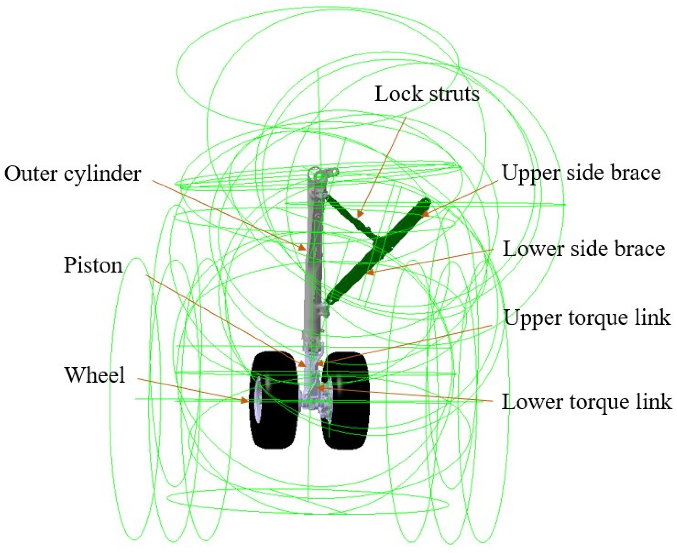
2.1. MBD Model of NLG

The simplified three-dimensional model of the NLG model is constructed, including the outer cylinder, turning sleeve, piston, upper and lower torque links, wheel, upper and lower resistance rods, lock struts, and the material properties are set. The NLG model is imported into the LMS Virtual.Lab Motion, and the corresponding constraint relationship and kinematic pair of the connecting parts are completed. The MBD model of the NLG is shown in Figure 2.
The mechanical model of the NLG system is mainly composed of force elements such as air spring force, oil damping force, structural limiting force, tire force and torsional damping force. It is realized by scalar expressions of force element, bump stop force element, standard bushing force element and complex tire force element, as shown in Table 1. Based on the analysis and theoretical derivation of the relevant load, the corresponding force element is applied in LMS Virtual.Lab Motion through parameter or function input.
The shock absorber in the landing gear is composed of the outer cylinder and the piston, which mainly absorbs the vertical kinetic energy during the landing and taxiing of the aircraft, and directly affects the stationarity of the aircraft. The data of the landing gear shock absorber are shown in Table 2.
Define the relative position of the coordinate system between the outer cylinder and the piston as the shock absorber stroke, and the air spring force is input in the form of expression, as shown below
F a = P a 0 V 0 V 0 A a S n P a t m A a
The oil-damping force is specified as
F d = d S ˙ 2 s i g n ( S ˙ )
where S ˙ and d designate stroke rate and damping coefficient, respectively. The oil damping coefficient d of the NLG shock absorber is variable, using a piecewise linear function, and there is a great difference between the positive and reverse stroke damping coefficient due to the diameter of the damping hole, as depicted in Figure 3.
The maximum stroke of the shock absorber is 0.43 m, and the structural limiting force is constrained by the bump stop force element to restrict the motion range of the piston. The structural limiting force is determined as
F 1 = k s t r u t S 0 k s t r u t S S max S 0 0 S S max S S max
There is an anti-shimmy damping hole in the turning control valve, and the oil flows through the damping hole to produce the anti-shimmy damping torque rotating around the axis of the pillar, so as to dissipate the mechanical energy of the shimmy and achieve the purpose of eliminating the shimmy. In LMS Virtual.Lab Motion, it is simplified to the damping moment between the turning sleeve and the outer cylinder, which is expressed by the standard bushing force element. The expression is given by
M D = C d θ ˙
where Cd is the torsional damping of NLG and θ ˙ is the angular velocity of rotation.
The tire force in NLG adopts the complex tire force element in LMS Virtual.Lab Motion, which is a tire model based on the Stretched String theory. The most widely used is Smiley’s second-order Stretched String theory model [26].
F t i r e = K λ λ 0 + C λ λ ˙ 0
M t i r e = K φ φ 0 + C φ φ ˙ 0
l 2 y ¨ 0 + V l 1 y ˙ 0 + V 2 λ 0 + V 2 l 1 θ s = 0
λ 0 = y 0 ( H + R ) α e e f f θ s
φ 0 = y ˙ 0 / V θ s
l 1 = H C A + L R
l 2 = H C A ( H C A + 2 L R ) / 2
where Ftire and Mtire are the force and moment acting on the tire on the ground, Kλ, Kφ, Cλ, Cφ are the lateral stiffness, torsional stiffness, lateral damping and torsional damping of the tire, respectively, y0 is the lateral offset of the tire touching the ground center, H is the vertical distance from the rotation axis to the wheel center, R is the rolling radius of the tire, α is the lateral rotation of the front wheel around the rotation axis, eeff is the equivalent stable distance, V is the taxiing speed of the aircraft, θs is the front wheel swing angle, HCA is the half length of the tire touching the ground and LR is the tire relaxation length.

2.2. MBD Model of MLG

On the basis of the NLG model, the left and right MLG parts are added by determining the coordinate position of MLG relative to NLG, which are mainly composed of the outer cylinder, piston, lock struts, resistance rod, torque link, wheel, etc. With reference to the modeling method of NLG, the modeling of force elements such as shock absorbers and tires is completed. Among them, the parameters of the MLG shock absorber refer to Table 2 and Figure 3, and the MBD model of MLG is established, as shown in Figure 4.

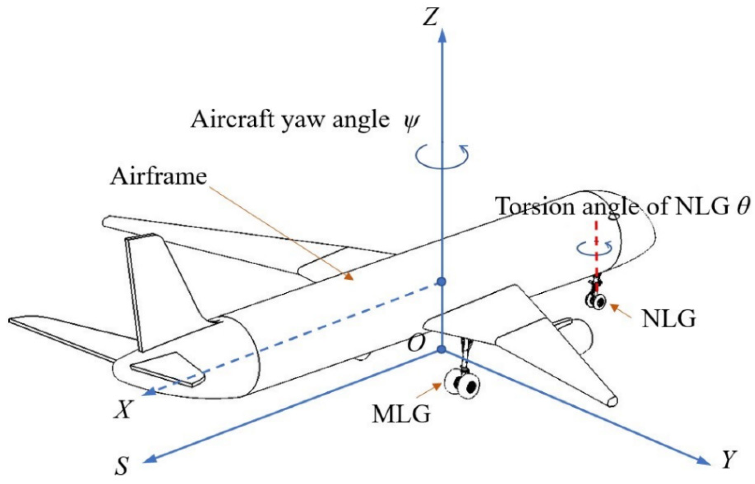
2.3. Airframe MBD Model and External Conditions

The MBD model of the airframe includes the mass of the body, the moment of inertia, the motion pair at the connecting point between the body and the landing gear and the aerodynamic force of the aircraft. After the model of the airframe and landing gear is completed, the runway can be further established, and the taxiing speed and initial excitation of the aircraft can be applied to simulate the taxiing process of the aircraft. The aircraft taxiing is driven by speed, accelerating from zero speed to a certain stable value, using the One-Body Velocity Driver command and applying it to the center of gravity of the aircraft coordinate system. When the taxiing speed of the aircraft is stable, at 20 s, an instantaneous force of 25,000 N is applied to the center of the left axle of the NLG and points in the x direction. The aerodynamic lift of the aircraft taxiing on the ground is
F A e r o = 1 2 ρ V 2 S e f f c
where FAero is the lift of the aircraft, ρ is the air density at the altitude of the aircraft, V is the taxiing speed, Seff is the equivalent area of the aircraft wing and c is the lift coefficient.
The aircraft taxiing MBD model considering many factors have been established, as shown in Figure 5. The main parameters are described in Table 3.

3. Results and Discussion

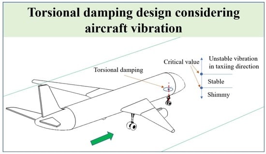
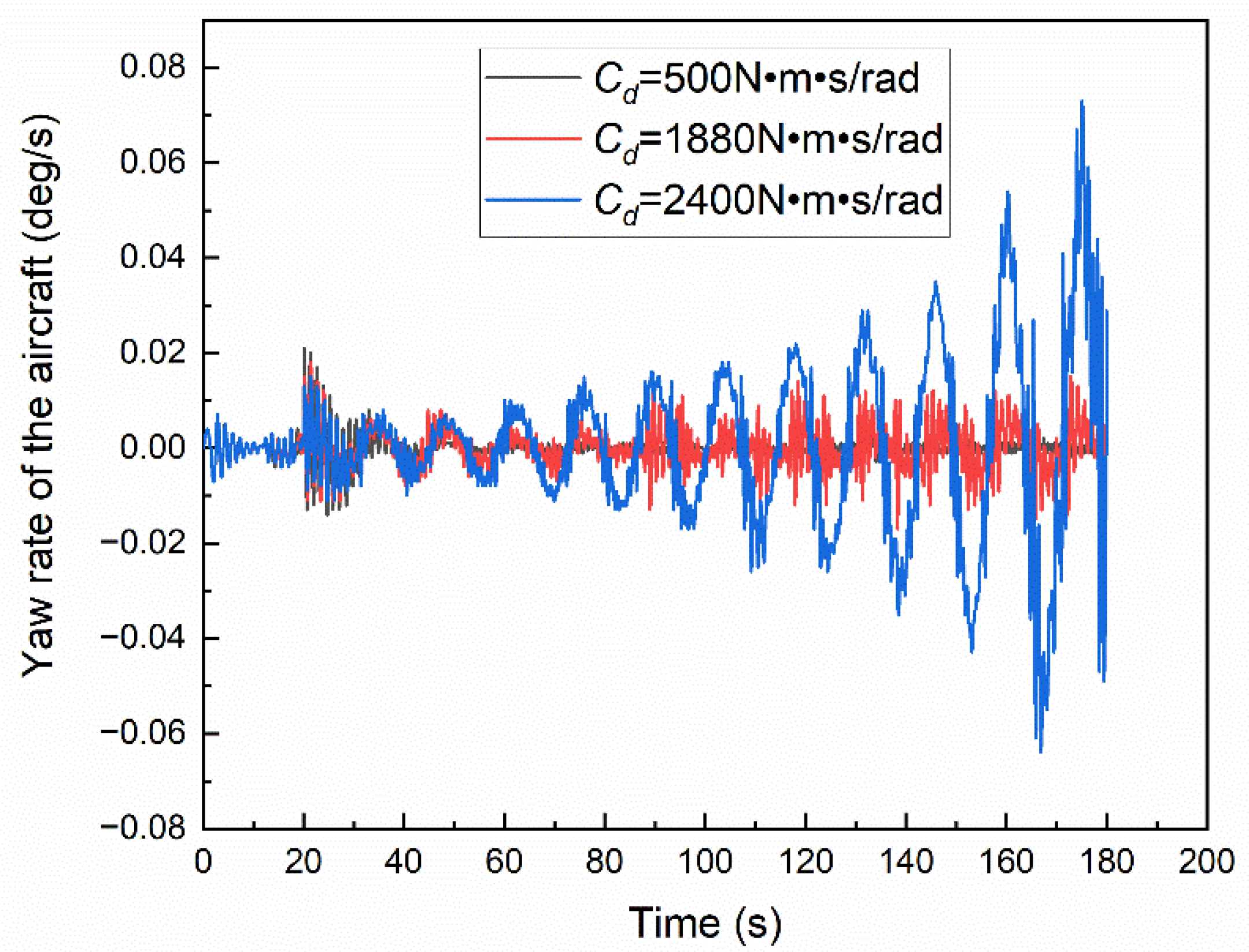
3.1. Relationship between Torsional Damping and Directional Stability of Aircraft

Using the aircraft MBD model established above, the initial condition of the simulation is the ground coordinate system X-direction velocity V = −60 m/s, and the ending time is 180 s, in which the take-off speed of the aircraft in this paper is 86 m/s. The torsional damping Cd is adjusted to 500 N m s/rad, 1880 N m s/rad, 2400 N m s/rad, respectively, and the effect of torsional damping on aircraft directional stability is studied. Among them, the critical value of 1880 N m s/rad is obtained from multiple debugging, as shown in Figure 6, Figure 7 and Figure 8, which shows the yaw rate and torsion angle of NLG during taxiing.
The yaw rate can directly reflect the direction stability of the aircraft during the taxiing process. If the taxiing direction of the aircraft is stable, the yaw rate of the aircraft must tend to 0; otherwise, there will be a yaw trend. Figure 6 shows the yaw rate of the aircraft under different torsional damping: when the torsional damping is 1880 N m s/rad, the yaw rate of the aircraft is approximately stable and oscillates within the amplitude of 0.01 deg/s; when the torsional damping is greater than the critical value, the yaw rate increases gradually, the vibration diverges and the direction of the aircraft is unstable; when the torsional damping is less than the critical value, the yaw rate of the aircraft gradually decreases to 0, the vibration converges and the direction of the aircraft is stable.
Figure 7 presents the time-domain curves of the torsion angle of NLG under different torsional damping, which is the same as the yaw rate of the aircraft: when the torsional damping is 1880 N m s/rad, the torsion angle of the NLG is approximately stable and oscillates within the amplitude of 1.5 deg; when the torsional damping is greater than the critical value, the vibration diverges, otherwise, the vibration converges. At the same time, it can also be observed in Figure 8 that under the instantaneous excitation of the left front wheel of 25,000 N, the initial torsion angle is different under different torsional damping. When the torsional damping is 500 N m s/rad, the initial torsional angle is 5 deg, so the smaller the torsional damping, the weaker the anti-interference ability. All of the above reflect the relationship between torsional damping and aircraft directional stability, which lays a foundation for further obtaining the critical torsional damping value.

3.2. Characteristics of Key Parameters in the Aircraft Taxiing Process

Little work has been performed on the characteristics of aircraft taxiing direction unstable self-excited vibration key parameters. Based on the established MBD model, this paper carries out related research, which is helpful for readers to deeply understand the process of aircraft’s taxiing direction unstable self-excited vibration.

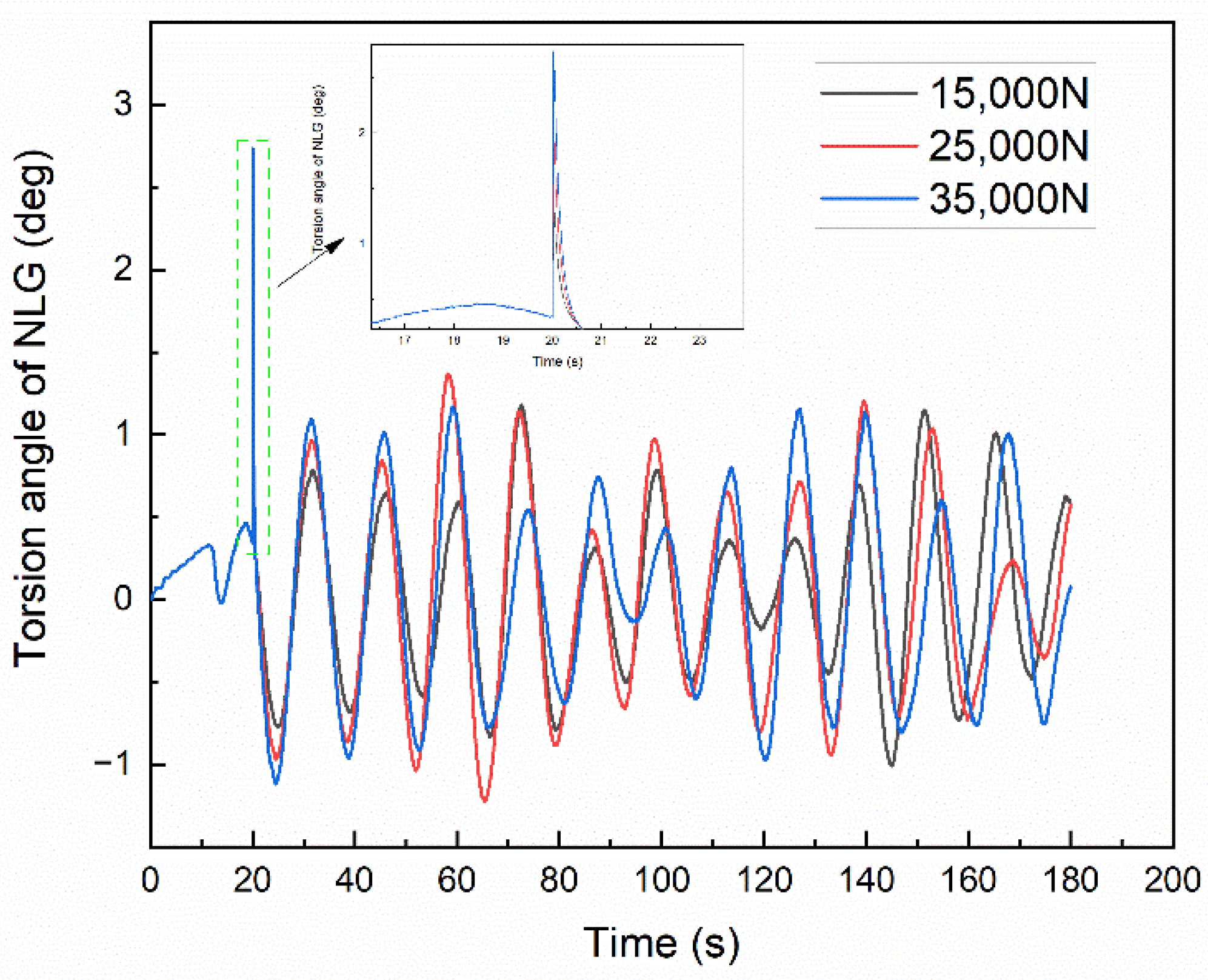
3.2.1. Initial Excitation

During the taxiing process of the aircraft on the airport runway, due to factors such as uneven road surface or crosswind, the initial excitation of the aircraft varies and is random. Figure 9 shows the influence of different initial excitations on the stability of the aircraft taxiing. When the torsional damping is 1880 N m s/rad, the time domain curves of the torsion angle of NLG under different initial excitations are obtained. The larger the excitation, the larger the initial torsion angle. Although there are fluctuations in the three curves, the results are all in a critical vibration state. It can be concluded that the initial excitation does not affect the critical torsional damping of aircraft taxiing.

3.2.2. Landing Gear Shock Absorber Compression

The landing gear struts vibrate up and down during the taxiing process of the aircraft, as shown in Figure 10, which shows the compression amount of the NLG and the MLG shock absorber under different torsional damping. The vibration of the NLG is more intense than that of the MLG, and the compression amount of the shock absorber is about 290 mm and 360 mm, respectively. When the torsional damping is small, it can be seen that the taxiing direction of the aircraft is stable according to the previous analysis, and the compression amount of the NLG shock absorber is small, while the corresponding MLG shock absorber compression amount is relatively large, so it can be concluded that when the direction of the aircraft is unstable, the vertical load of the NLG will increase.
When the torsional damping is 2400 N m s/rad, the taxiing direction of the aircraft is unstable. As can be seen from Figure 11, the compression amount of the MLG shock absorber also shows a fluctuation phenomenon with gradually increasing amplitude, and there is a 180° phase angle in the compression amount fluctuation curve of the left and right MLG shock absorbers. Combined with the curve of the torsion angle of NLG, when the NLG rotates to the left, the right MLG bears a more vertical load, so the compression of the right MLG shock absorber is large, and the compression of the left MLG shock absorber is small.

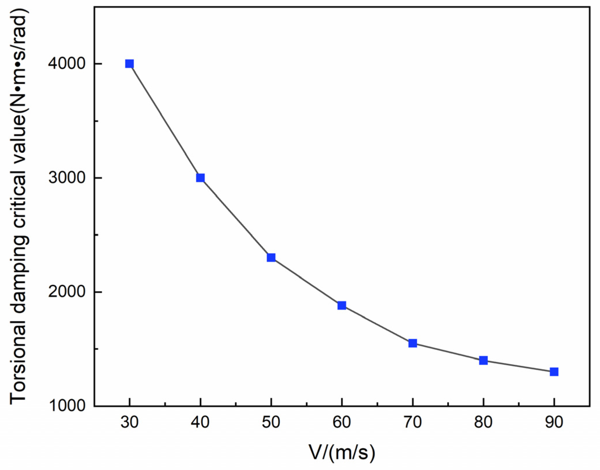
3.3. Torsional Damping Critical Value

For a given type of aircraft, many structural parameters such as caster length and tires have been determined, while the taxiing speed has been changing from 0 to the take-off speed value of 86 m/s, in which the high speed stage of taxiing is the same as the ground rolling that takes off or landing on the runway, and the low speed stage of taxiing refers to taxiing on the taxiway. The direction stability of the aircraft is different under different speed conditions, so the taxiing speed range is 30 m/s~90 m/s to cover the typical taxiing speed of the aircraft. In addition to the anti-sway capability of the landing gear itself, the aircraft is mainly stabilized by the torsional damper. According to the analysis results obtained above, the upper critical value of the torsional damping under different taxiing speeds is further studied, and the results are depicted in Figure 12.
It can be seen from the table that as the taxiing speed increases, the critical torsional damping for the stability of the aircraft taxiing direction decreases. When the maximum speed is 90 m/s, it can be considered as the most unstable moment in the taxiing direction of the aircraft, and the critical torsional damping is about 1300 N m s/rad, which is the design reference value for the upper limit of the damping in the anti-shimmy system and requires special attention.

3.4. NLG Shimmy and Aircraft Directional Stability

Previous analysis has shown that when the torsional damping is excessive, the aircraft direction is unstable. However, many scholars have found that if torsional damping is insufficient, the NLG shimmy will occur. In order to further study the stability of the aircraft with small torsional damping, take the torsional damping of 100 N m s/rad to carry out an aircraft taxiing simulation. The results are shown in Figure 13.
When the torsional damping is 100 N m s/rad, the NLG has a shimmy phenomenon and eventually converges as seen in Figure 13a; the aircraft also vibrates in an unstable direction, which also converges quickly, but their vibration frequencies are different, the shimmy frequency of the NLG is 6.191 Hz, which is the same as the research literature on shimmy [17,27,28], and the unstable vibration of the aircraft direction is 0.064 Hz, as described in Figure 13b. This result confirms that different self-excited vibrations occur when the aircraft is taxiing. In summary, the NLG shimmy and the unstable vibration of the aircraft direction belong to different vibration modes, which may occur during the taxiing process of the aircraft, so in the design phase of the NLG system, in order to improve the reliability of the aircraft, the potential harm of different self-excited vibration should be considered.

4. Conclusions

In order to improve the damping design of the NLG anti-shimmy system, the critical value of torsional damping is proposed and analyzed in this paper. Through the aircraft MBD model established in LMS Virtual.Lab Motion, the influence of torsional damping of NLG on the stability of aircraft taxiing direction is studied, and the critical values of different taxiing speeds are obtained. It has important engineering application value for the design of the torsional damping of NLG.
The results show that when the torsional damping is a critical value, the degrees of freedom, such as the torsion angle of NLG and yaw rate are all vibrated with equal amplitudes; and when the torsional damping is less than the critical value, the directional stability motion parameters converge and the direction is stable; otherwise, it is unstable. The large airliner is prone to directional unstable vibration in the high-speed zone, and the maximum torsional damping corresponding to the velocity 90 m/s is about 1300 N m s/rad. It is further found that the aircraft nose wheel shimmy and the aircraft direction unstable vibration occurred simultaneously, when the torsional damping is 100 N m s/rad, the nose wheel shimmy occurs after the excitation, the frequency is about 6 Hz, but the unstable vibration in the aircraft direction is less than 0.1 Hz, and the two kinds of vibration converge finally. In other words, considering the above two kinds of vibration are necessary for the damping design of the anti-shimmy system.

Author Contributions

Conceptualization: Y.J. and G.F.; Investigation: P.L., L.Y. and J.D.; Methodology: Y.J., G.F. and B.J.; Project administration: B.J.; Software: Y.J. and J.D.; Super-vision: G.F. and B.J.; Writing—original draft: Y.J.; Writing—review and editing, B.J. All authors have read and agreed to the published version of the manuscript.

Funding

This work was funded by the Civil Aircraft Special Project of the MIIT, grant number JZ025-XY-003.

Institutional Review Board Statement

Not applicable.

Informed Consent Statement

Not applicable.

Data Availability Statement

Not applicable.

Acknowledgments

The authors gratefully acknowledge the research grant provided by the Civil Aircraft Special Project of the MIIT (Grant No. JZ025-XY-003) in support of this work.

Conflicts of Interest

The authors declare no conflict of interest.

References

  1. Depei, Z. Shimmy Theory and Anti-Shimmy Measure; National Defense Industry Press: Beijing, China, 1984. [Google Scholar]
  2. Feng, F.; Nie, H.; Zhang, M.; Peng, Y. Effect of Torsional Damping on Aircraft Nose Landing-Gear Shimmy. J. Aircr. 2015, 52, 561–568. [Google Scholar] [CrossRef]
  3. Rahmani, M.; Behdinan, K. Interaction of Torque Link Freeplay and Coulomb Friction Nonlinearities in Nose Landing Gear Shimmy Scenarios. Int. J. Non. Linear. Mech. 2020, 119, 103338. [Google Scholar] [CrossRef]
  4. Gordon, J.T. Perturbation Analysis of Nonlinear Wheel Shimmy. J. Aircr. 2002, 39, 305–317. [Google Scholar] [CrossRef]
  5. Arreaza, C.; Behdinan, K.; Zu, J.W. Linear Stability Analysis and Dynamic Response of Shimmy Dampers for Main Landing Gears. J. Appl. Mech. Trans. ASME 2016, 83, 081002. [Google Scholar] [CrossRef]
  6. Rahmani, M.; Behdinan, K. Investigation on the Effect of Coulomb Friction on Nose Landing Gear Shimmy. JVC/J. Vib. Control 2019, 25, 255–272. [Google Scholar] [CrossRef]
  7. Suresh, P.S.; Sura, N.K.; Shankar, K. Investigation of Nonlinear Landing Gear Behavior and Dynamic Responses on High Performance Aircraft. Proc. Inst. Mech. Eng. Part G J. Aerosp. Eng. 2019, 233, 5674–5688. [Google Scholar] [CrossRef]
  8. Tartaruga, I.; Lowenberg, M.H.; Cooper, J.E.; Sartor, P.; Lemmens, Y. Bifurcation Analysis of a Nose Landing Gear System. In Proceedings of the 15th Dynamics Specialists Conference, San Diego, CA, USA, 4–8 January 2016. [Google Scholar] [CrossRef] [Green Version]
  9. Tourajizadeh, H.; Zare, S. Robust and Optimal Control of Shimmy Vibration in Aircraft Nose Landing Gear. Aerosp. Sci. Technol. 2016, 50, 1–14. [Google Scholar] [CrossRef]
  10. Orlando, C.; Alaimo, A. A Robust Active Control System for Shimmy Damping in the Presence of Free Play and Uncertainties. Mech. Syst. Signal Process. 2017, 84, 551–569. [Google Scholar] [CrossRef]
  11. Sanches, L.; Guimarães, T.A.M.; Marques, F.D. Nonlinear Energy Sink to Enhance the Landing Gear Shimmy Performance. Acta Mech. 2021, 232, 2605–2622. [Google Scholar] [CrossRef]
  12. Orlando, C. Nose Landing Gear Simple Adaptive Shimmy Suppression System. J. Guid. Control. Dyn. 2020, 43, 1298–1312. [Google Scholar] [CrossRef]
  13. Rahmani, M.; Behdinan, K. Parametric Study of a Novel Nose Landing Gear Shimmy Damper Concept. J. Sound Vib. 2019, 457, 299–313. [Google Scholar] [CrossRef]
  14. Rahmani, M.; Behdinan, K. On the Effectiveness of Shimmy Dampers in Stabilizing Nose Landing Gears. Aerosp. Sci. Technol. 2019, 91, 272–286. [Google Scholar] [CrossRef]
  15. Mustashin, M.S.; Rahmani, M.; Behdinan, K. Experimental Characterization of a Novel Nose Landing Gear Shimmy Damper Using a Small-Scale Test Rig. Aerosp. Sci. Technol. 2021, 112, 106625. [Google Scholar] [CrossRef]
  16. Cheng, L.; Cao, H.; Zhang, L. Two-Parameter Bifurcation Analysis of an Aircraft Nose Landing Gear Model. Nonlinear Dyn. 2021, 103, 367–381. [Google Scholar] [CrossRef]
  17. Thota, P.; Krauskopf, B.; Lowenberg, M. Bifurcation Analysis of Nose-Landing-Gear Shimmy with Lateral and Longitudinal Bending. J. Aircr. 2010, 47, 87–95. [Google Scholar] [CrossRef] [Green Version]
  18. She, C.; Zhang, M.; Ge, Y.; Tang, L.; Yin, H.; Peng, G. Design and Simulation Analysis of an Electromagnetic Damper for Reducing Shimmy in Electrically Actuated Nose Wheel Steering Systems. Aerospace 2022, 9, 113. [Google Scholar] [CrossRef]
  19. Rahmani, M.; Behdinan, K. Structural Design and Optimization of a Novel Shimmy Damper for Nose Landing Gears. Struct. Multidiscip. Optim. 2020, 62, 2783–2803. [Google Scholar] [CrossRef]
  20. Li, Y.; Howcroft, C.; Neild, S.A.; Jiang, J.Z. Using Continuation Analysis to Identify Shimmy-Suppression Devices for an Aircraft Main Landing Gear. J. Sound Vib. 2017, 408, 234–251. [Google Scholar] [CrossRef]
  21. Coetzee, E.; Krauskopf, B.; Lowenberg, M. Continuation Analysis of Aircraft Ground Loads during High-Speed Turns. J. Aircr. 2013, 50, 217–231. [Google Scholar] [CrossRef]
  22. Yin, Q.; Nie, H.; Wei, X. Dynamics and Directional Stability of High-Speed Unmanned Aerial Vehicle Ground Taxiing Process. J. Aircr. 2020, 57, 689–701. [Google Scholar] [CrossRef]
  23. Huang, Z.; Best, M.; Knowles, J. An Investigation of a High-Speed Ground Manoeuvre under Optimal Control. Proc. Inst. Mech. Eng. Part G J. Aerosp. Eng. 2019, 233, 4363–4379. [Google Scholar] [CrossRef]
  24. Rankin, J.; Coetzee, E.; Krauskopf, B.; Lowenberg, M. Bifurcation and Stability Analysis of Aircraft Turning on the Ground. J. Guid. Control. Dyn. 2009, 32, 499–510. [Google Scholar] [CrossRef] [Green Version]
  25. Song, L.; Yang, H.; Yan, X.; Ma, C.; Huang, J. A Study of Instability in a Miniature Flying-Wing Aircraft in High-Speed Taxi. Chinese J. Aeronaut. 2015, 28, 749–756. [Google Scholar] [CrossRef] [Green Version]
  26. Smiley, R.F. Correlation, Evaluation, and Extention of Linearized Theories for Tire Motion and Wheel Shimmy; NACA TN-3632; National Advisory Committee for Aeronautics: Washington, WA, USA, 1956. [Google Scholar]
  27. Ran, S.; Besselink, I.J.M.; Nijmeijer, H. Application of Nonlinear Tyre Models to Analyse Shimmy. Veh. Syst. Dyn. 2014, 52, 387–404. [Google Scholar] [CrossRef]
  28. Thota, P.; Krauskopf, B.; Lowenberg, M. Interaction of Torsion and Lateral Bending in Aircraft Nose Landing Gear Shimmy. Nonlinear Dyn. 2009, 57, 455–467. [Google Scholar] [CrossRef]
Figure 1. Coordinate system and main parameters of aircraft taxiing.
Aerospace 09 00729 g001
Figure 2. MBD model of the NLG.
Aerospace 09 00729 g002
Figure 3. Oil damping coefficient of positive and reverse stroke of landing gear shock absorber.
Aerospace 09 00729 g003
Figure 4. MBD model of the MLG.
Aerospace 09 00729 g004
Figure 5. MBD model of aircraft taxiing.
Aerospace 09 00729 g005
Figure 6. Effect of torsional damping on aircraft yaw rate.
Aerospace 09 00729 g006
Figure 7. Effect of torsional damping on torsion angle of NLG.
Aerospace 09 00729 g007
Figure 8. Torsion angle of NLG with different torsional damping under the same initial excitation.
Aerospace 09 00729 g008
Figure 9. Effect of initial excitation on Torsion angle of NLG.
Aerospace 09 00729 g009
Figure 10. Effect of torsional damping on compression of landing gear shock absorber.
Aerospace 09 00729 g010
Figure 11. Compression of left and right MLG shock absorbers with torsional damping of 2400 N m s/rad.
Aerospace 09 00729 g011
Figure 12. Critical value Cd of torsional damping at different taxiing speeds.
Aerospace 09 00729 g012
Figure 13. Relationship between NLG shimmy and aircraft directional stability with torsional damping of 100 N m s/rad. (a) Torsion angle of NLG; (b) Frequency of vibration.
Aerospace 09 00729 g013
Table 1. Summary of load application.
No.Load TypeForce Element
1Air spring forceScalar Expression Force
2Oil damping forceScalar Expression Force
3Structural limiting forceBump Stop Force
4Torsional damping torqueStandard Bushing
5Tire forceComplex Tire
Table 2. Landing gear shock absorber data.
ParameterDescriptionValue of NLGValue of MLGUnit
Pa0Initial gas pressure2,425,0002,843,000Pa
V0Initial gas volume3.059 × 10−31.17 × 10⁻²m3
AaPressure area 7.11 × 10−32.47 × 10−2m2
ρOil density860860kg/m3
PatmAtmospheric pressure1,010,0001,010,000Pa
nAir variability index1.11.1-
kstrutStructural limited stiffness1.96 × 1081.96 × 108N/m
SmaxMaximum stroke0.430.47m
SStroke--m
Table 3. Main parameters of airframe and landing gear.
ParameterDescriptionValueUnit
Airframe
mGAircraft mass72,500kg
IxAirframe moment of inertia about roll axis2,175,000Kg m2
IyAirframe moment of inertia about strut axis3,630,000Kg m2
IzAirframe moment of inertia about pitch axis900,000Kg m2
Landing gear structural
lqLongitudinal distance from nose wheel to center of gravity12.715m
lzLongitudinal distance from main wheel to center of gravity0.753m
IMoment of inertia of the NLG about the orientation axis1.75Kg m2
tCaster length38mm
CdTorsional damping-N m s/rad
Tire of NLG
RNRadius of tire0.3854m
KNVertical stiffness of tire1,174,000N/m
bqTorsional stiffness of tire7746N m/rad
NqCornering stiffness of tire173,088.9N/m
KδLateral stiffness of tire392,273.7N/m
KβLongitudinal stiffness of tire786,381.1N/m
Tire of MLG
RMRadius of tire0.6248m
KMVertical stiffness of tire1,364,000N/m
bzTorsional stiffness of tire9295.2N m/rad
NzCornering stiffness of tire207,692N/m
External conditions
ρAir density at the altitude of the aircraft1.29kg/m3
SeffEquivalent area of aircraft wing129.15m2
cLift coefficient0.5-
μTire rolling friction coefficient0.04-
NNose wheel vertical load7000*9.8N
VTaxiing speed-m/s
Publisher’s Note: MDPI stays neutral with regard to jurisdictional claims in published maps and institutional affiliations.

