Article

Comparative Study of the Thermal Enhancement for Spacecraft PCM Thermal Energy Storage Units

School of Aeronautic Science and Engineering, Beijing University of Aeronautics and Astronautics, Beijing 100191, China
*
Author to whom correspondence should be addressed.
Aerospace 2022, 9(11), 705; https://doi.org/10.3390/aerospace9110705
Submission received: 26 August 2022 / Revised: 3 November 2022 / Accepted: 3 November 2022 / Published: 10 November 2022

Abstract

:
To access the enhancement effect of the topology optimization and porous foam structure, numerical studies were conducted to investigate the heat conduction enhancement (by metal foam, graphite foam, topologically optimized fins, and combinations of metal foam and topologically optimized fins) of phase change material (PCM (n-octadecane)) based tubular thermal energy storage unit for spacecraft. The results showed that metal foam performed better than topologically optimized fins and a combination of metal foam and topology optimized fins, of which conductive material, unit mass, and volume fraction of PCM were the same. Graphite foam (140 W/(m·K)) had the best heat transfer enhancing effect, making PCM melt much faster than other enhancing methods investigated. A multi-criteria decision-making (MCDM) method integrated with the combined weight and TOPSIS method was introduced to evaluate the preferred alternatives’ performance based on the energy storage time, equivalent density, and energy storage. The evaluation pointed out that 3% topologically optimized aluminum fins with 98% copper foam had the best comprehensive performance. This study guided the optimal design of latent heat thermal energy storage units for spacecraft under microgravity.

1. Introduction

Phase change materials (PCM) can absorb/release large amounts of latent heat near the isothermal range. Thus, PCM-based thermal storage technologies are widely used in solar photothermal power generation [1], low-temperature refrigeration [2], building HVAC [3], thermal management of electric vehicles [4], and spacecraft thermal control [5,6]. Both organic PCMs and low melting point alloys can be used for thermal management. Still, the high density of low melting point alloys [7] hinders their application in space and mass-limited vehicles. Other PCMs, of which low thermal conductivity suppresses the rapid heat absorption, cannot be directly used for applications. Therefore, numerous studies have extensively investigated the heat transfer enhancement of PCM-based thermal storage devices.
The addition of highly conductive foam media to PCMs proves very effective [8]. Rehman et al. [9] experimentally investigated two PCM-based heat sinks that contain RT35HC with copper foam (97% porosity, 35 PPI) and RT45HC with copper foam. The experimental results showed that, with 40 °C and 60 °C as the temperature control target, the temperature control time was eight times and 7.7 times longer than that of paraffin only. Zhang et al. [10] used different porous models to simulate the melting process of the composite PCM of aluminum foam (95% porosity) and paraffin. The results demonstrated that the melting time of the composite PCM was reduced by 26–28% compared to that of pure paraffin. Wang et al. [11] conducted an experimental study for the higher alcohol/graphite foam-based heat sink. The experimental results found that the enhanced heat transfer by graphite foam was mainly reflected in the latent heat stage. With 90 °C as the temperature control target, the composite PCM-based heat sink’s thermal control time was 24% longer than that of the pure higher alcohol-based heat sink. Besides high thermal conductivity medium, adding fins in PCM-based heat sinks is also an effective way to enhance heat transfer. Desai [12] et al. studied the effect of different shapes of pin fins in the heat sinks and concluded that trigonal fins had the largest heat transfer area compared to contrasting fins. Thus, the heat sink with trigonal fins had the lowest “limit critical temperature”. In addition, the combination of fin and metal foam can further increase the heat transfer rate of the PCM heat storage unit. Kothari et al. [13] added a composite PCM of copper foam and paraffin to the heat sink with fins. They found that the above heat sink performed better at higher heat flux (2.0 and 2.7 W/cm2).
In recent years, with the synergistic development of additive manufacturing, topologically optimized structures break through processing limitations and can be widely used to enhance heat transfer [14]. Alexandersen and Sigmund et al. [15,16] designed a heat sink with topologically optimized fins for LED devices under natural convection. Their study proved that the topologically optimized heat sink had better thermal performance than the straight fin and lattice one. The work of Pizzolato [17,18] and Tian et al. [19] performed topology optimization for tube-fin PCM-based thermal energy storage units. The optimization results indicated that considering the natural convection of liquid PCM affected the topology optimized configuration, and the topology configuration considering natural convection was more advantageous in energy storage rate. Moreover, the topologically optimized fins are more effective than the conventional straight fins regardless of whether natural convection is considered.
Different ways of enhancing phase change heat transfer have their characteristics, and therefore different enhancement ways for latent heat thermal energy storage units need to be evaluated comparatively. Yang et al. [20] addressed the problem of PCM preference for ground-source heat pumps. The authors used a combination of subjective and objective weight methods to assign weights to the different properties of the alternative PCMs. Finally, they selected the best PCM, barium octahydrate hydroxide. Similarly, Oluah [21] et al. applied the entropy-weighted TOPSIS method to conduct a multi-criteria decision-making (MCDM) on the alternative PCMs for latent heat thermal energy storage in Trombe walls. The study’s results indicated that the highest weight, which was 72%, was assigned to the thermal conductivity of the PCMs. The capric and palmitic acids were preferentially selected. Therefore, for different latent energy storage units, the MCDM method can help us determine the optimal alternatives.
Few cross-sectional comparative studies and evaluations have been conducted on the enhanced heat transfer of PCM units utilizing the above means. This paper employed numerical simulations to study the thermal performance under microgravity conditions based on the PCM thermal energy storage units for spacecraft. N-octadecane was selected as the PCM, while graphite foam, aluminum foam, copper foam (porosity 90%, 95% (PPI = 10/20/40), 98%), topologically optimized fins, and the combination of the latter two were used as thermal conductivity enhancer. The simulation results were evaluated by an MCDM method. Then, the analytic hierarchy process and entropy information method combined with the TOPSIS method was adopted for MCDM, which considered the PCM thermal energy storage unit’s mass (equivalent density), storage energy (PCM volume fraction) and energy storage rate (energy storage time) as indicators. Moreover, the realizability of the enhancement method was discussed. The study implements a basis for designing PCM thermal storage and management equipment for spacecraft.

2. Physical and Mathematical Models

2.1. Latent Heat Thermal Energy Storage Units for Spacecraft

Figure 1 addresses a tubular PCM thermal energy storage unit. The tube has a radius of r0 = 15 mm or less to represent the fluid. The annular space with an outer diameter of r1 = 40 mm and an inner diameter of r0 = 15 mm is filled with a PCM and a thermal conductivity enhancer to absorb heat from a hot fluid or to release heat to a cold fluid. The unit can be applied for thermal control and thermal management of spacecraft.

2.1.1. Selection of the PCM

PCMs are used as heat sinks and heat sources for spacecraft thermal management due to their isothermal absorption and heat release. Organic phase change materials have high latent heat, high stability, good compatibility, and low density and are widely available. Among them, paraffin and alkanes are more widely used, and alkane PCMs have higher latent heat and no supercooling. Considering the operating temperature of the spacecraft, we selected n-octadecane, an organic PCM with high latent heat but melting at approximately 6 °C with low thermal conductivity, which is commonly chosen in studies [22] for spacecraft thermal control.

2.1.2. Selection of the Thermal Conductivity Enhancers (TCE)

It is vital to enhance the heat transfer of PCMs with low thermal conductivity. Materials such as aluminum, copper, and graphite are commonly applied in spacecraft, and their porous materials are also excellent thermal conductivity enhancers for PCMs.
The metal fins integrated with topological optimization and topologically optimized fins combined with metal foam were designed for n-octadecane as the different thermal conductivity enhancers. Copper foam, aluminum foam, and graphite foam were utilized as well. A two-dimensional cross-section (Figure 1) of the thermal energy storage unit is chosen to simplify the simulation. The thermal properties of materials are shown in Table 1.
According to the review literature [8], the porosity of commonly used copper foam is above 95%, while the porosity of aluminum foam is below 95% and mostly less than 90%. To control the two variables of unit mass and PCM volume fraction in the following paper, we determined the porosity (79%/91.6%/95%) of aluminum foam from three kinds of copper foam (90%/95%/98%), respectively. In addition, to investigate the influence of the pore density of the metal foam, three pore densities (10/20/40 PPI) of 95% copper foam were chosen.
Typically, graphite foam with a porosity of 75% is prepared. Due to differences in preparation processes, the physical properties of graphite foams, especially the equivalent thermal conductivity, vary excessively. The reference [8] reports a distribution in the range of 24.7–240 W/(m·K) in terms of equivalent thermal conductivity for graphite foam with 75% porosity, but other thermo-properties are close. Here the physical properties of well-known POCO FOAM graphite foam [23] were employed for the calculations, and three representative values of 4, 40, and 140 were taken to reflect the influence of the equivalent thermal conductivity.

2.2. Simulation of PCM Charging Process

2.2.1. Mathematical Formulation

The enthalpy model was used to simulate the phase change process, and the following assumptions were made to facilitate the study.
  • All materials, including porous foam media, are homogeneous.
  • The volume change of the PCMs during melting and the thermal capillary convection at the free surface is neglected.
  • Natural convection within the PCMs is considered negligible under microgravity conditions.
Based on the above assumptions, only heat conduction was considered, and the continuity and momentum equations were eliminated.
Metal fin region:
t ρ TCE H TCE = k TCE T TCE
Pure PCM region:
t ρ PCM ε H PCM = ε k PCM T PCM + h f s A fs T TCE T PCM
Porous foam medium region:
t ρ TCE ( 1 ε ) H TCE = ( 1 ε ) k TCE , eff T TCE h fs A fs T TCE T PCM
In Equations (1)–(3), ρ is the density, T is the temperature, H is the enthalpy, k is the thermal conductivity, hfs is the local heat transfer coefficient, Afs is the contact area between the PCM and the porous foam medium, and ε is the porosity of the porous foam medium. The subscript PCM represents the phase change material, TCE represents the thermal conductivity enhancer, and eff represents the equivalent thermal conductivity. Where the enthalpy H is the sum of the sensible enthalpy h and the latent heat ΔH.
H = h + ΔH
h = h ref + T ref T c p d T
ΔH = γL
γ is the liquid fraction of the PCM during the phase change process, and L is the latent heat of the PCM.
γ = 0 T T s T T s / T l T s T s < T < T l 1 T T l

2.2.2. Initial and Boundary Conditions

The initial moment temperature was set to 298.15 K to ensure that the PCM was solid.
Ti = 298.15 K (t = 0)
The temperature of the inner wall surface with radius r0 was set to 373.15 K:
Tw= 373.15 K
The expression for kTCE,eff for a porous foam medium is [24]:
k TCE , eff = ( 1 ε ) 1 e + 3 e 2 α 3 ( 1 e ) + 3 2 α e k TCE
where the geometrical parameters e and α of the porous foam structure are obtained by fitting and are 0.3 and 1.5, respectively.
The reference [25] gives the hfs and Afs of copper foam with around 95% porosity with PCM without considering the flow heat transfer, and the values are taken in Table 2.

2.3. Topology Optimization Methodology

2.3.1. Solid Isotropic Material with Penalization (SIMP) Method

Topological optimization techniques in heat transfer can achieve the optimal material space distribution of high thermal conductivity materials in the zone fulfilling low thermal conductivity material, to achieve the optimal thermal index. A density-based topology optimization approach is used in this study. This entails discretizing the design domain into finite elements and assigning each element a material pseudo-density, θ ∊ [0, 1], which functions as the design variable. Power and linear functions implemented SIMP method to scale material properties [26] by Equations (11)–(13), where the power function applied to interpolate the thermal conductivity reduces the contribution of intermediate values to heat transfer.
k ( x ) = k PCM + θ ( x ) p k TCE k PCM
ρ ( x ) = ρ PCM + θ ( x ) ρ TCE ρ PCM
c p ( x ) = c p , PCM + θ ( x ) c p TCE c p PCM
c p , PCM = c p , s T T s c p , s + L T l T s T s < T < T l c p , l T T l
where the subscript PCM represents phase change material or a composite of PCM and metal foam; TCE represents copper or aluminum. p is the penalty factor, generally taken as p = 3.; x denotes the material cell location, and the two materials are interpolated on the finite element nodes by Equation (15) in the design domain. This approach makes the pseudo-density of the elements tend to 0 or 1 (0 represents PCM and 1 represents TCE), declines the elements with intermediate density, and finally can make the material properties of each finite element close to those of PCM or TCE.
( ρ ( x ) H ( x , t ) ) t = ( k ( x ) T ( x , t ) )
Equation (15) is solved in each optimization iteration, and the optimal distribution of temperature Topt and materials θopt can be obtained after the optimization results converge.

2.3.2. Objective Function

The mathematical expression of the optimization problem is as follows [26]:
Minimize
F ( θ ) = Ω T ( k ( θ ) T ) d Ω subject   to   θ d Ω d   Ω φ 0 θ 1
where Ω represents the design domain, and φ is the volume fraction of the thermal conductivity enhancer. This study aimed to enhance the heat transfer of PCM in the LHTES unit by minimizing the global temperature distribution of the domain. According to the reference [17,26,27], the thermal compliance, which is characteristic of the dissipation of heat transfer capacity, was adapted to the objective function F by Equation (16).

2.3.3. Other Descriptions

The initial and boundary conditions for the optimization were set as in Section 2.2.2. A Helmholtz filter based on a partial differential equation is required to avoid mesh dependency in the topology optimization problem. Additionally, a hyperbolic tangent projection is used to reduce the gray area in-between the PCM-TCE domains. An in-depth description of the topology optimization techniques used in this study, including extensive details on the density filtering and projection methods, is given in reference [17,26].

2.4. Numerical Method

The numerical simulation of the melting process was carried out in ANSYS Fluent with the relevant parameter settings, as detailed in our previous work [28].
The optimization process was performed by COMSOL Multiphysics, with the initial material pseudo-density θ and the penalty factor p taken to be 0.5 and automatic, respectively. The transient calculation time step was 0.01 s. The complete melting of the PCM was set as the stopping condition for the transient calculation, and the pseudo-density was calculated and updated using the global convergence method of moving asymptote (GCMMA). The maximum total number of iteration steps was 1000, the residual was 10−6, and the hyperbolic tangent projection was adopted to obtain a clear structural boundary.

2.5. Model Validation

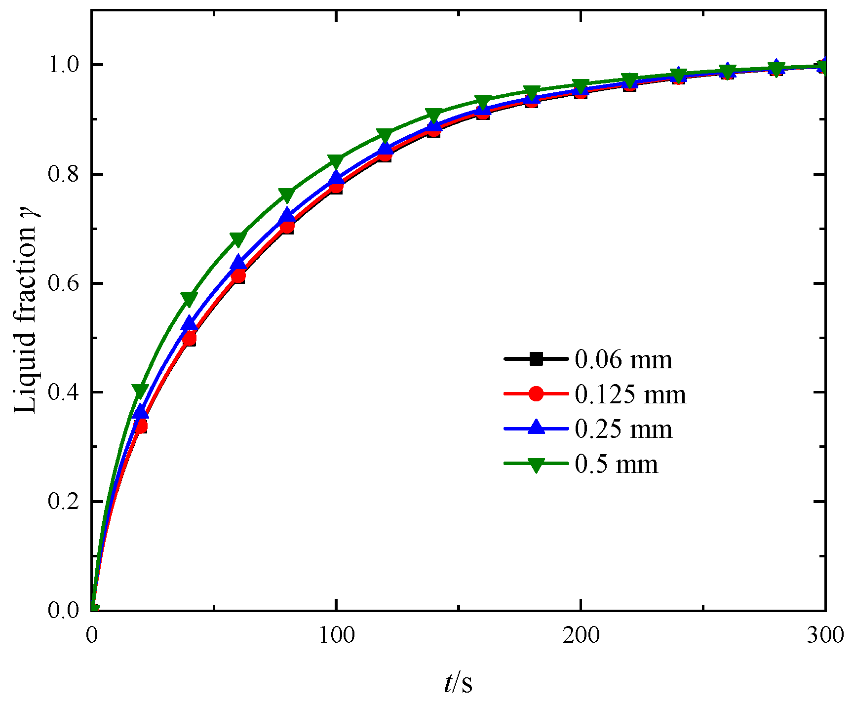
2.5.1. Independent Verification

The unit with a 21% volume fraction of topologically optimized aluminum fins was simulated numerically, and the average mesh sizes of 0.06 mm, 0.125 mm, 0.25 mm, and 0.5 mm were selected to obtain the average liquid phase fraction profiles of the PCM as shown in Figure 2. The average errors between the liquid fraction curves of 0.125 mm and 0.25 mm and 0.06 mm were 0.3% and 1.6%, and the mesh size of 0.125 mm was chosen to be sufficient for other working conditions. Figure 3 shows the liquid fraction curves with different time steps using the 0.125 mm grid, and the error between the curves does not exceed 3% as the time step varies from 0.01 s to 0.1 s. Thus, 0.05 s is selected.

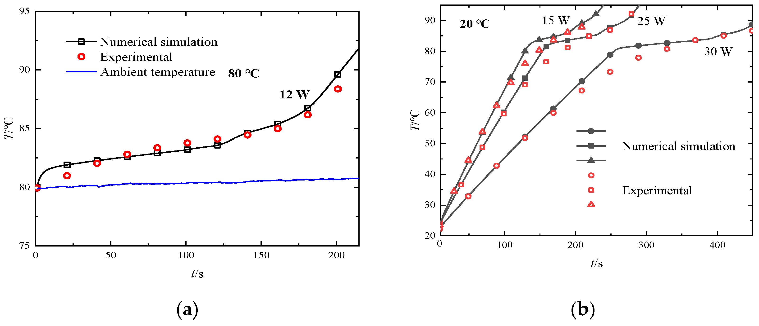
2.5.2. Comparison of Numerical Method and Experiment

The validity of numerical simulations on enthalpy models for metal foam/PCM was described in our previous work [28]. While the validation of the numerical simulations on the foam graphite/phase change material was achieved through experiments on a heat sink with dimensions of 50 mm × 50 mm × 10 mm (shown in Figure 4b) in a natural convection environment at 80 °C. The experimental setup is shown in Figure 4c, with an aluminum alloy shell with a wall thickness of 2 mm and a composite PCM of 75% graphite foam and higher alcohol inside, with an electric heater at the bottom of the heat sink to supply a constant heat flux.
Figure 5 demonstrates the temperature profiles of the heater at different ambient temperatures and powers. The numerical simulation results match well with the experimental results, and the errors are within 4%, so the numerical model and algorithm can be considered reliable.

2.6. Multi-Criteria Decision Making

2.6.1. Subjective Weight: Analytic Hierarchy Process

The analytic hierarchy process is one of the most commonly used methods in subjective weighting, which usually requires the following five steps to complete the determination of subjective weights.
  • Construct a hierarchical model based on the actual situation, divided into the target layer, criterion layer, and solution layer;
  • Construct a comparison matrix by comparing the criteria two by two based on a 9-point scale [29].
  • Normalize the comparison matrix (n-th order square matrix), find the maximum eigenvalue λmax and perform the consistency test:
    C I = λ max n n 1
    where n is the number of criteria, and there are three criteria in this study.
    C R = C I R I
  • RI is the random index, which can be found in reference [30]. If RI < 0.1, the consistency is considered good; if RI > 0.1, a new comparison matrix needs to be reconstructed to improve the consistency.
  • Derive the weight matrix w j 1 based on the comparison matrix.

2.6.2. Objective Weight: Entropy Method

The entropy method assesses the uncertainty in information and is derived from probability theory. The concept of entropy was introduced by Shannon and is widely used in engineering, medicine, and economics to solve decision problems. Entropy measures the degree of disorder in a system and represents the degree of dispersion of a data indicator. If the degree of disorderliness of an indicator is greater, its entropy value is larger, indicating that the indicator contains more information and its weight is greater. Conversely, the weight is smaller [21]. For a data set with m alternatives and n characteristics, the entropy method requires that a decision matrix is first created:
X = x i j = x 11 x 12 x 1 n x 21 x 22 x 2 n x m 1 x m 2 x m n
where i represents the i-th alternative and j represents the j-th characteristic.
The second step requires normalization of the data to facilitate arithmetic between different data.
y i j = x i j min x i j max x i j min x i j or max x i j x i j max x i j min x i j
when xij is a positive indicator, the former is used; when xij is a negative indicator, yij is the latter.
The entropy value ej is defined as
e j = 1 ln m i = 1 m y i j ln y i j
In the third step, the weight wj is calculated using the entropy value.
w j 2 = 1 e j j = 1 n 1 e j

2.6.3. TOPSIS Method

The TOPSIS method [20,21] is a numerical method for solving multi-criteria decision problems, which is based on the principle of ranking alternatives using the similarity of Euclidean distance between them and the optimal solution. The process of the TOPSIS method is as follows.
First, the normalized matrix zij weighted by the hierarchical analysis and entropy weighting methods is calculated.
z i j = w j x i j
For each characteristic, there are optimal values and inferior solutions among the alternatives, which correspond to 1 × n-dimensional matrices.
Z+ = max(zj)
Z = max(zj)
Thus, for each alternative, the Euclidean distances from its optimal and inferior solutions are
Z + = j = 1 n Z + Z i j 2
Z = j = 1 n Z Z i j 2
Finally, the performance scores Pi are obtained by
Pi = Z/(Z+ + Z)
The value of Pi is between (0, 1) and closer to 1 indicating that the alternative is closer to the ideal optimal solution.

2.6.4. Combination of Weights

The combination weights wj were determined by weighting the subjective and objective weights.
w j = α w j 1 + β w j 2
where α and β are weighting coefficients and α + β = 1.
It was wanted that the data for MCDM was spread out as much as possible to facilitate the ranking, so the objective based on the maximum sum of squared deviations was implemented, which led to α and β. The detailed derivation is given in reference [31].

3. Results

Twenty alternatives were designed and numerically simulated, denoted by the abbreviations No. 1–20. The alternatives were designed with copper foam compounded with n-octadecane as the basis, as shown in Table 3, which also gives the equivalent densities of the PCM units and the volume fraction of n-octadecane φPCM. Certain alternatives have the same mass or PCM volume fraction. CF, AF, TOCF, TOAF, and GF are abbreviations for copper foam, aluminum foam, topology-optimized copper fins, topology-optimized aluminum fins, and graphite foam, respectively. The percentages after the foam media are the porosity, while the percentages after the topology-optimized fins represent the volume fraction. The k after alternatives 18–20 represents the equivalent thermal conductivity of graphite foam.

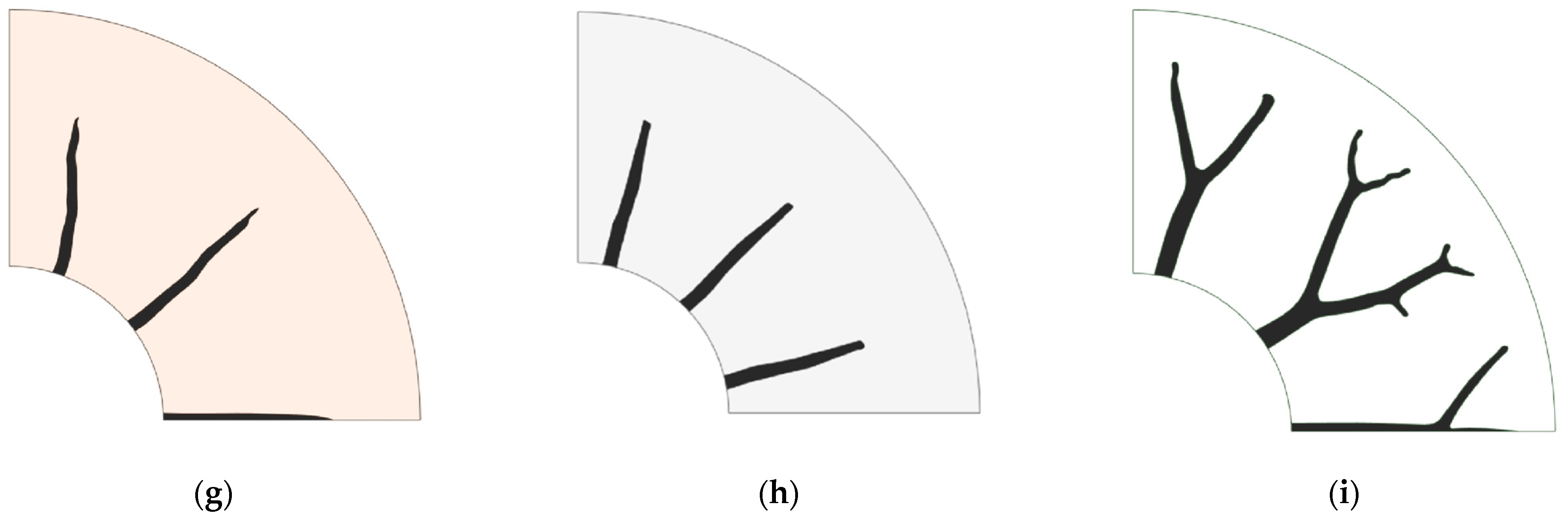
3.1. Topology Optimization Result

The fins were topologically optimized for nine combinations in this work, and the computational domain for optimizations was taken as half of the PCM unit. The results are demonstrated in Figure 6, which shows only 1/4 of the units. The white region represents pure PCM (n-octadecane), the orange region represents the composite PCM with copper foam, and the gray region represents the composite PCM with aluminum foam. At a sufficiently large volume fraction of the fins, the fins all generate a tree-like branching structure, similar to the patterns obtained in other literature. However, when the volume fraction of the fins is tightened, the optimized fin structures, shown in Figure 6e,g,h, do not branch and are no different from that of conventional straight fins.
The ratio kTCE/kTCE,eff of the thermal conductivity of the fin material kTCE to the equivalent thermal conductivity of the PCM kTCE,eff affects the fin pattern details. The tips of the branches become sharp from plus rounded as kTCE/kTCE,eff increases, which is compounded by physical intuition because the highly conductive fin structure has to generate more branches to the low thermal conductivity region to transfer heat to accelerate the heat absorption in the whole domain. Another insight is that for low melting point alloys (low melting point alloy) [7], which are used to facilitate fast heat dissipation in high-power electronic devices, kTCE/kTCE,eff = 1.6, is very small. At this point, topology optimization techniques may not be very effective for LMPA cells, and the results can be aesthetically unsatisfactory.

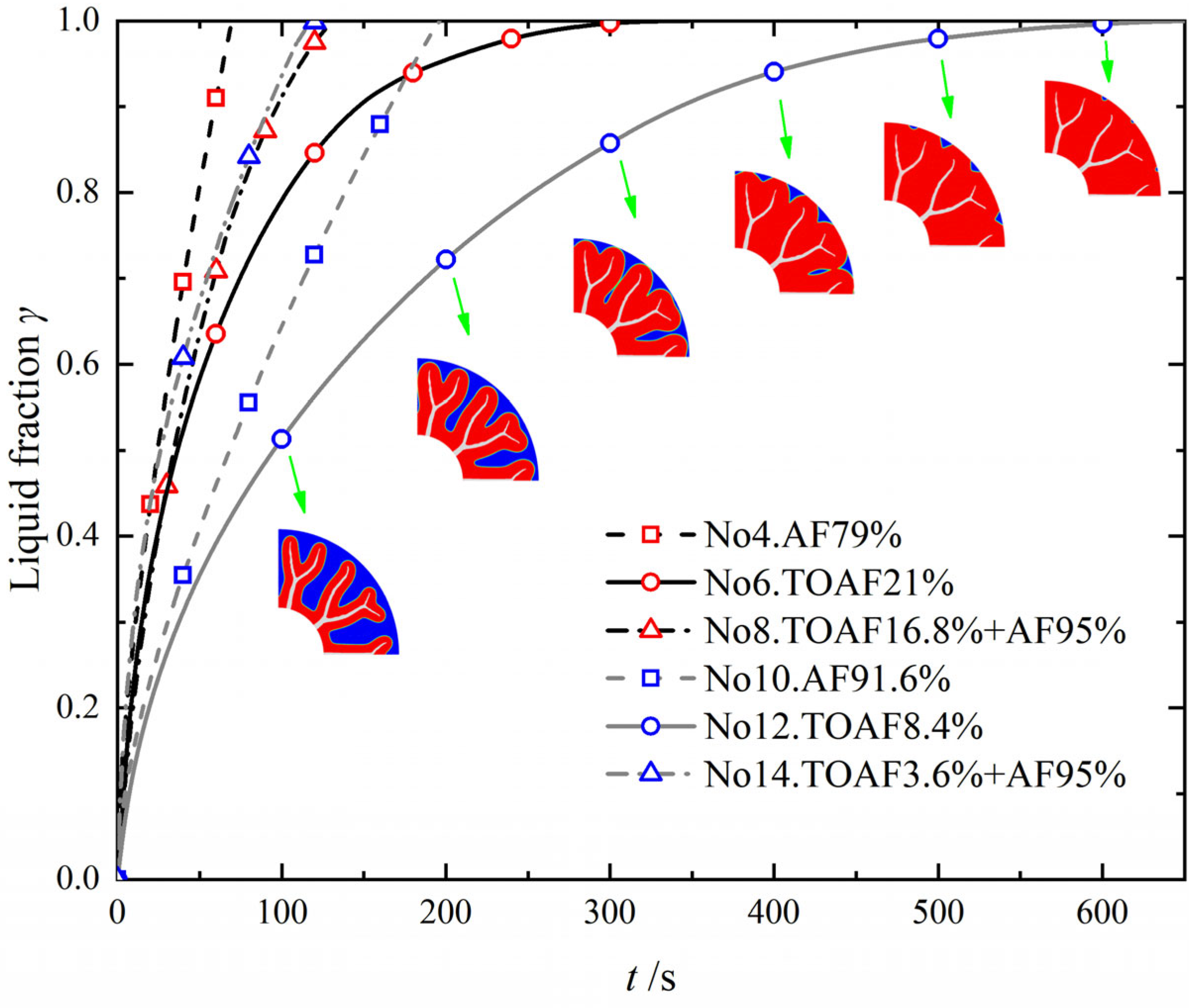
3.2. Numerical Simulation Result

The relationship between the energy storage time te and the average energy storage (melting) rate vm for each alternative PCM unit is given in Figure 7. The energy storage time te is the time for the liquid phase fraction of the PCM reaches 99%; vm is defined by the equation:
vm = φPCM/te
Figure 7 shows that each alternative’s relative relationship between te and vm is consistent. Due to the high thermal conductivity of graphite foam (k = 140 W/(m·K)), the melting time of No. 20 was only 9.9 s, which was much less than the other alternatives. No. 19 (k = 40 W/(m·K)) came in second place and had a relatively high thermal conductivity, so it still had some advantages relative to the others. No. 4 and No. 15 were followed by the melting rate (less than 100 s). From Figure 6, it can be found that these two alternatives achieved a short te due to metal foam’s low porosity and, therefore, high equivalent thermal conductivity. No. 8 was the next best, combining the advantages of topologically optimized fins and aluminum foam in high conductivity and uniform heat transfer with a small amount of n-octadecane, thus achieving a faster energy storage rate. However, No. 11 and No. 5 with a melting time of more than 1000 s, was ranked last because the volume fraction of fins were too tiny to achieve uniform heat transfer enhancement inside the PCM, as in the case of metal foam.
Figure 8 depicts the melting liquid phase fraction versus time for several alternatives. No. 4–No. 8 have the same ρeff and φPCM, as do No. 10–No. 14. It can be concluded that the enhancing effect by metal foam was the best for the same conditions, which was better than the combination of aluminum foam and fins. Because the fins’ presence limited the metal foam’s porosity with which they were combined under the same ρeff and φPCM constraints, the high thermal conductivity fins with higher porosity aluminum foam were worse than the low porosity one in terms of heat transfer uniformity. The alternative with only topologically optimized aluminum fins had the longest te, which was much inferior to the aluminum foam with the same volume fraction. For No. 6 and No. 12, the melting rate of n-octadecane was decreased in the post stages of melting, and the enhancing effect was depleted due to the limited area touched by the multi-stage branches of the fins, which was more evident in the melting cloud in Figure 8. Because of this, the te of No. 5 and No. 11 was much longer than the others. However, the more important conclusion was that the heat transfer enhancement of the metal foam was the best among the modalities we studied with the same mass of the energy storage unit and the PCM storage capacity as a guarantee.
The melting rate curves for all the alternatives enhanced with porous foam are demonstrated in Figure 9. It is clear from the characteristics of the curves that the variation of the liquid phase fraction with time is uniform due to the presence of the porous medium. The magnitude of the slope of the curves roughly reflects the equivalent thermal conductivity of the foam medium kTCE,eff (Equation (11)). The equivalent thermal conductivity of the foam medium was approximately halved for each doubling of te. Hence, the porous skeleton material was significant for enhancing heat transfer. The thermal conductivity of graphite foam in No. 18 was only 4 W/(m·K), which was larger than No. 9 and less than No. 17 in terms of melting rate. However, it was the worst in heat storage capacity because the porosity of graphite foam was only 75%. Therefore, having a high thermal conductivity larger than 16 W/(m·K) is the key for graphite foam to take advantage. In addition, the melting curves of No. 1–No. 3 are similar, but the melting was slightly faster at higher pore densities, which was caused by the local non-equilibrium heat transfer coefficient hfs and the area density Afs between copper foam and PCM with increasing porosity, see Table 2. Meanwhile, when the copper foam’s PPI was large enough, the melting curves converged to those simulated using the local equilibrium model with sufficient accuracy. However, when the metal fins were combined with the porous structure, the local non-equilibrium phenomenon inside the energy storage unit was more serious, and the simulation with the local equilibrium model would produce significant errors.
Combining the above parts of the discussion, the enhancing effect of the foam medium is significant in the tubular energy storage unit. In No. 9, even 98% of copper foam improved the thermal conductivity of n-octadecane by more than ten times. Moreover, the combination of topologically optimized fins and metal foam dependent on the same ρeff and φPCM constraint did not have an advantage in enhancing heat transfer. However, the lightweight aluminum fins with high-porosity copper foam can obtain a lower mass, more PCM filling, and higher heat transfer capability, achieving a balance of energy storage and energy storage rate.

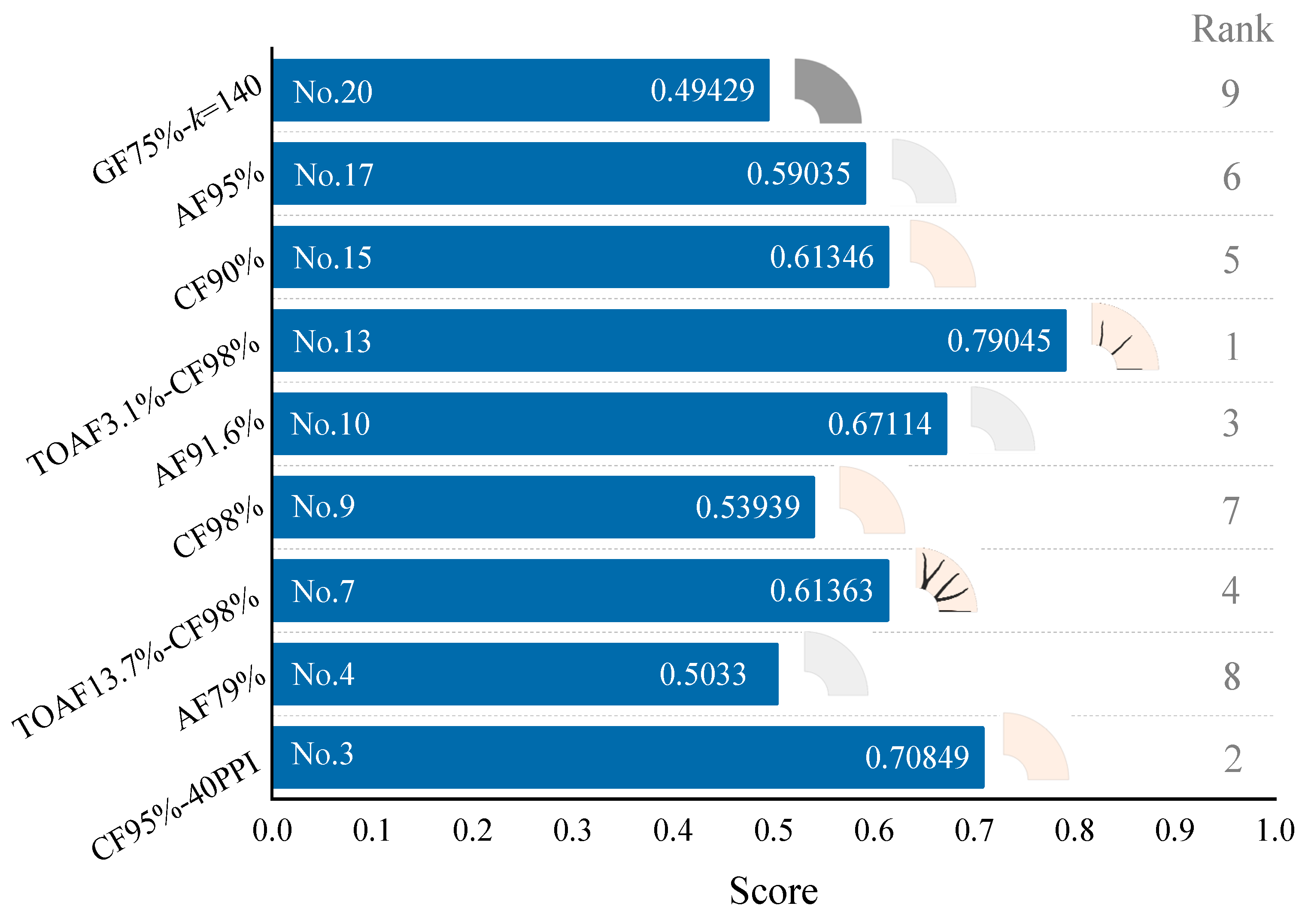
3.3. Evaluation Result of TOPSIS Method

Ground-based equipment is not sensitive to the weight of the thermal energy storage unit. Nonetheless, for spacecraft-borne equipment, the mass becomes an important consideration. In this section, three characteristics, the melting time te of the PCM, the equivalent density ρeff of the thermal energy storage unit, and the volume fraction φPCM of the PCM, are applied to make a comprehensive evaluation of each alternative.
From the results in Table 4, the 20 alternatives were selected, and it is easy to find that No. 3/4/7/9/10/13/15/17/20 has a more dominant melting time for the same ρeff or φPCM, so the nine alternatives were extracted for evaluation.
The comparison matrix obtained using the methodological approach in Section 2.6 is
t e ρ eff φ PCM t e 1 3 1 ρ eff 1 / 3 1 1 / 3 φ PCM 1 3 1
The normalized subjective weight matrix was obtained accordingly
w1 = [0.4286, 0.1428, 0.4286]T
The objective weight matrix obtained by the entropy weighting method:
w2 = [0.3351, 0.2780, 0.3870]T
The weighting coefficients were from calculating the maximum sum of squares of deviations as the objective function
[α, β] = [0.5213, 0.4787]
Finally, the weight matrix of the combination was
w = [0.3838, 0.2075, 0.4087]T
As shown in Figure 10, among the subjective weights, the weights assigned to te and φPCM were equally significant, and the weight of ρeff was 1/3 of the other two. Among the objective weights (Figure 10), the weights assigned to te and φPCM are lower than the subjective weights, φPCM had the most significant influence on the comprehensive performance of the thermal energy storage unit, and te was slightly second, which was as well in the combined weights. ρeff is assigned the smallest weight because φPCM is coupled with ρeff. The value of ρeff was the least dispersed from the performance data. That is, the information entropy of this index is smaller, and therefore its weight from the entropy method is also smaller.
Figure 11 lists the comprehensive ranking of the nine alternatives. No. 13 combined the aluminum fin and copper foam structure characteristics, maintained a high porosity, and was at the top of the ranking. No. 3 and No. 10 were ranked second and third due to the metal foam’s higher thermal conductivity and porosity. The combination of aluminum rib structure and copper foam, No. 7, was only in fourth place, with the same mass as No. 3, but the aluminum fins reduced the volume of PCM, which was not as good as No. 3 in terms of all-around performance. No. 20, which was in last place, the ultra-high thermal conductivity of graphite foam failed to compensate for its low porosity. In addition, looking at the ranking characteristics of several options, it can be found that in a similar form, the copper foam was better than aluminum foam, even if the copper foam was slightly inferior in density, but both were better than graphite foam.
Since the weights of te and φPCM were similar, only the solution with outstanding thermal conductivity and heat storage can stand out, which is also consistent with the results obtained above. Based on the results of several alternatives evaluated, the enhancement of aluminum fins with high porosity copper foam was chosen as the best scheme to meet the requirements of high thermal conductivity, large energy storage, and low weight. It was worth noting that the best alternative’s volume fraction of the fin was smaller and did not bifurcate so that a straight fin can replace it. However, geometric parameters such as length and width need to be obtained by optimal design. The calculation of topology optimization is still necessary, considering that many arithmetic examples are needed for parameter optimization.

3.4. Further Discussion

During the previous analysis, we comprehensively evaluated three vital characteristics of the thermal energy storage units. In applications, other factors affect the design of energy storage units, such as structural strength, processing difficulty, and cost. However, these factors did not been considered quantitatively in the study. The topologically optimized fins combined with metal foam have hardly been applied to the best of the authors’ knowledge, one of the reasons being the difficulty of processing, including the welding of the foam metal to the fins and the shell as well as PCM filling. Nevertheless, this solution is not infeasible. In recent years, due to the development and maturity of metal additive manufacturing technology, the processing of complex fins can break free from the constraints of traditional processing methods [32]. Recently, spacecraft energy storage devices also used lattices to strengthen the structure, which had better welding properties. Thus, considering the process issues, a lattice structure can replace the metal foam. Alternatively, a similar design can be achieved by topology optimization with variable gradient lattices [33], but its high-density part is unfavorable to the filling of PCM and tends to cause underfilling.
From Section 3.3, No. 7 (or even No. 8) was not ranked at the top. Both have a larger volume fraction (>10%) of the fins, which was not the optimal choice for energy storage units. In this study, the boundary condition is constant wall temperature, but the electronic device thermal design boundary condition is usually constant heat flux to check the junction temperature. Bifurcated fins combined with metal foam or lattices may facilitate the thermal design of electronic devices, so No. 7 may perform better under the constant heat flux. Regarding graphite foam (No. 20), its ultra-high heat transfer enhancement and low porosity are more suitable for heat dissipation devices. In addition, the spacecraft environment requires enough structural strength for the energy storage unit under internal pressure, which hinders the application of graphite foam. Graphite foam is not as widely available, and only a few institutions have mastered its mature preparation process, affecting equivalent thermal conductivity. As reported in the review literature [8], the equivalent thermal conductivity of graphite foam varies. It is only competitive if its equivalent thermal conductivity reaches tens of W/(m·K). Although the high cost of graphite foam is inappropriate for mass-produced devices, the cost is not an essential factor for spacecraft. Moreover, the merit of graphite foam as a high-performance enhancing medium for other thermal control equipment remains outstanding.

4. Conclusions

This study investigated the thermal conductivity enhancing structure of a tubular latent heat thermal energy storage unit for spacecraft under microgravity. Fins of different structures and fins combined with metal foam are presented by topology optimization, which was also studied in a comparative numerical simulation with the conventional porous foam medium, then the comprehensive performance of the preferred alternatives was evaluated. Based on the above, the following conclusions were obtained.
  • The graphite foam-based PCM thermal energy storage unit melted the fastest, but its low porosity made the heat storage less, which was unsuitable for enhancing heat transfer for spacecraft after a comprehensive evaluation.
  • Only topologically optimized fins were also unsuitable because the reinforcement effect is not apparent when the fin volume fraction was small; when the fin volume fraction was large, the PCM filling decreased.
  • Porous foam medium (aluminum foam, copper foam, and graphite foam) enhanced PCM melting well. The copper foam was better than aluminum foam, and the foam media had the best enhancing effect for the same metal material, mass, and heat storage.
  • The topologically optimized aluminum fins with a small volume fraction combined with high porosity copper foam ranked the best in the comprehensive assessment within the studied range. The metal foam can be replaced by a lattice structure and processed using additive manufacturing considering practical factors.

Author Contributions

Conceptualization, S.W.; methodology, S.W. and X.H.; software, S.W. and X.H.; validation, S.W. and X.H.; investigation, S.W., J.Y. and Z.W.; resources, S.W., J.Y. and Z.W.; data curation, S.W., J.Y. and Z.W.; writing—original draft preparation, S.W.; writing—review and editing, S.W. and Y.X.; visualization, S.W.; supervision, Y.X.; project administration, Y.X.; funding acquisition, Y.X. All authors have read and agreed to the published version of the manuscript.

Funding

This research was funded by Aeronautical Science Foundation of China, grant number 20172851018.

Data Availability Statement

Not applicable.

Conflicts of Interest

The authors declare no conflict of interest.

References

  1. Kumar, A.; Tiwari, A.K.; Said, Z. A comprehensive review analysis on advances of evacuated tube solar collector using nanofluids and PCM. Sustain. Energy Technol. Assess. 2021, 47, 101417. [Google Scholar] [CrossRef]
  2. Selvnes, H.; Allouche, Y.; Manescu, R.I.; Hafner, A. Review on cold thermal energy storage applied to refrigeration systems using phase change materials. Therm. Sci. Eng. Prog. 2020, 22, 100807. [Google Scholar] [CrossRef]
  3. Raquel, L.; Luis, B. Phase change materials and energy efficiency of buildings: A review of knowledge. J. Energy Storage 2020, 27, 101083. [Google Scholar] [CrossRef]
  4. Thakur, A.K.; Prabakaran, R.; Elkadeem, M.R.; Sharshir, S.W.; Arici, M.; Wang, C.; Zhao, W.; Hwang, J.-Y.; Saidure, R. A state of art review and future viewpoint on advance cooling techniques for Lithium–ion battery system of electric vehicles. J. Energy Storage 2020, 32, 101771. [Google Scholar] [CrossRef]
  5. Garmendia, I.; Vallejo, H.; Seco, M.; Anglada, E. Design and fabrication of a phase change material heat storage device for the thermal control of electronics components of space applications. Aerospace 2022, 9, 126. [Google Scholar] [CrossRef]
  6. Raj, C.R.; Suresh, S.; Bhavsar, R.R.; Singh, V.K.; Govind, K.A. Influence of fin configurations in the heat transfer effectiveness of Solid-solid PCM based thermal control module for satellite avionics: Numerical simulations. J. Energy Storage 2020, 29, 101332. [Google Scholar] [CrossRef]
  7. Zhao, L.; Xing, Y.; Liu, X. Experimental investigation on the thermal management performance of heat sink using low melting point alloy as phase change material. Renew. Energy 2020, 146, 1578–1587. [Google Scholar] [CrossRef]
  8. Ali, H.M.; Janjua, M.M.; Sajjad, U.; Yan, W.M. A critical review on heat transfer augmentation of phase change materials embedded with porous materials/foams. Int. J. Heat Mass Transf. 2019, 135, 649–673. [Google Scholar] [CrossRef]
  9. Ali, H.M.; Saieed, A.; Pao, W.; Ali, M. Copper foam/PCMs based heat sinks: An experimental study for electronic cooling systems. Int. J. Heat Mass Transf. 2018, 127, 381–393. [Google Scholar] [CrossRef]
  10. Zhang, Z.; Cheng, J.; He, X. Numerical simulation of flow and heat transfer in composite PCM on the basis of two different models of open-cell metal foam skeletons. Int. J. Heat Mass Transf. 2017, 112, 959–971. [Google Scholar] [CrossRef]
  11. Wang, S.; Xing, Y.; Hao, Z.; Yin, J.; Hou, X.; Wang, Z. Experimental study on the thermal performance of PCMs based heat sink using higher alcohol/graphite foam. Appl. Therm. Eng. 2021, 198, 117452. [Google Scholar] [CrossRef]
  12. Desai, A.N.; Gunjal, A.; Singh, V.K. Numerical investigations of fin efficacy for phase change material (PCM) based thermal control module. Int. J. Heat Mass Transf. 2020, 147, 118855. [Google Scholar] [CrossRef]
  13. Kothari, R.; Sahu, S.K.; Kundalwal, S.I.; Mahalkar, P. Thermal performance of phase change material–based heat sink for passive cooling of electronic components: An experimental study. Int. J. Energy Res. 2021, 45, 5939–5963. [Google Scholar] [CrossRef]
  14. Dbouk, T. A review about the engineering design of optimal heat transfer systems using topology optimization. Appl. Therm. Eng. 2017, 112, 841–854. [Google Scholar] [CrossRef]
  15. Alexandersen, J.; Sigmund, O.; Meyer, K.E.; Lazarov, B.S. Design of passive coolers for light-emitting diode lamps using topology optimisation. Int. J. Heat Mass Transf. 2018, 122, 138–149. [Google Scholar] [CrossRef] [Green Version]
  16. Lazarov, B.S.; Sigmund, O.; Meyer, K.E.; Alexandersen, J. Experimental validation of additively manufactured optimized shapes for passive cooling. Appl. Energy 2018, 226, 330–339. [Google Scholar] [CrossRef] [Green Version]
  17. Pizzolato, A.; Sharma, A.; Maute, K.; Sciacovelli, A.; Verda, V. Design of effective fins for fast PCM melting and solidification in shell-and-tube latent heat thermal energy storage through topology optimization. Appl. Energy 2017, 208, 210–227. [Google Scholar] [CrossRef]
  18. Pizzolato, A.; Sharma, A.; Ge, R.; Maute, K.; Verda, V.; Sciacovelli, A. Maximization of performance in multi-tube latent heat storage–Optimization of fins topology, effect of materials selection and flow arrangements. Energy 2020, 203, 114797. [Google Scholar] [CrossRef]
  19. Tian, Y.; Liu, X.; Xu, Q.; Luo, Q.; Zheng, H.; Song, C.; Xuan, Y. Bionic topology optimization of fins for rapid latent heat thermal energy storage. Appl. Therm. Eng. 2021, 194, 117104. [Google Scholar] [CrossRef]
  20. Yang, K.; Zhu, N.; Chang, C.; Wang, D.; Yang, S.; Ma, S. A methodological concept for phase change material selection based on multi-criteria decision making (MCDM): A case study. Energy 2018, 165, 1085–1096. [Google Scholar] [CrossRef]
  21. Oluah, C.; Akinlabi, E.T.; Njoku, H.O. Selection of phase change material for improved performance of Trombe wall systems using the entropy weight and TOPSIS methodology. Energy Build. 2020, 217, 109967. [Google Scholar] [CrossRef]
  22. Peng, H.; Yan, W.; Wang, Y.; Feng, S. Discharging process and thermal evaluation in the thermal energy storage system with fractal tree-like fins. Int. J. Heat Mass Transf. 2022, 183, 122073. [Google Scholar] [CrossRef]
  23. POCOGraphite. Pocofaom Thermophysical Properties. Available online: http://www.poco.com/Portals/0/Literature/Semiconductor/78962v2PocoFoamFlyer.pdf (accessed on 1 May 2022).
  24. Yang, X.H.; Bai, J.X.; Yan, H.B.; Kuang, J.J.; Lu, T.J.; Kim, T. An analytical unit cell model for the effective thermal conductivity of high porosity open-cell metal foams. Transport Porous Med. 2014, 102, 403–426. [Google Scholar] [CrossRef]
  25. Di Giorgio, P.; Iasiello, M.; Viglione, A.; Mameli, M.; Filippeschi, S.; Di Marco, P.; Bianco, N. Numerical analysis of a paraffin/metal foam composite for thermal storage. J. Phys. Conf. Ser. 2017, 796, 012032. [Google Scholar] [CrossRef]
  26. Ho, J.Y.; See, Y.S.; Leong, K.C.; Wong, T.N. An experimental investigation of a PCM-based heat sink enhanced with a topology-optimized tree-like structure. Energy Convers. Manag. 2021, 245, 114608. [Google Scholar] [CrossRef]
  27. Guo, Z.; Cheng, X.; Xia, Z. Principle of Minimum heat transfer potential capacity dissipation and its application in heat conduction optimization. Chin. Sci. Bull. 2003, 48, 21–25. (In Chinese) [Google Scholar] [CrossRef]
  28. Hou, X.; Xing, Y.; Hao, Z. Multi-objective optimization of a composite phase change material-based heat sink under non-uniform discrete heating. Appl. Therm. Eng. 2021, 197, 117435. [Google Scholar] [CrossRef]
  29. Xu, H.; Romagnoli, A.; Sze, J.Y.; Py, X. Application of material assessment methodology in latent heat thermal energy storage for waste heat recovery. Appl. Energy 2017, 187, 281–290. [Google Scholar] [CrossRef]
  30. Sánchez-Lozano, J.M.; García-Cascales, M.S.; Lamata, M.T. GIS-based onshore wind farm site selection using fuzzy multi-criteria decision making methods. Evaluating the case of Southeastern Spain. Appl. Energy 2016, 171, 86–102. [Google Scholar] [CrossRef]
  31. Chen, W.; Xia, J. An optimal weights combination method considering both subjective and objective weight information. Pract. Knowl. Math. 2007, 37, 17–22. (In Chinese) [Google Scholar]
  32. Iradukunda, A.C.; Vargas, A.; Huitink, D.; Lohan, D. Transient thermal performance using phase change material integrated topology optimized heat sinks. Appl. Therm. Eng. 2020, 179, 115723. [Google Scholar] [CrossRef]
  33. Cheng, L.; Liu, J.; To, A.C. Concurrent lattice infill with feature evolution optimization for additive manufactured heat conduction design. Struct. Multidiscip. O. 2018, 58, 511–535. [Google Scholar] [CrossRef]
Figure 1. 3D and 2D schematic diagrams of thermal energy storage unit.
Aerospace 09 00705 g001
Figure 2. Grid independence validation.
Aerospace 09 00705 g002
Figure 3. Time step independence validation.
Aerospace 09 00705 g003
Figure 4. Higher alcohol/graphite foam-based heat sink. (a) Micrograph of higher alco-hol/graphite foam. (b) Encapsulated heat sink. (c) Experimental apparatus.
Aerospace 09 00705 g004
Figure 5. Temperature profiles of higher alcohol/graphite foam-based heat sink. (a) Temperature profile of heat source at 80 °C 12 W. (b) Temperature profiles of heat source at 80 °C for varied powers.
Aerospace 09 00705 g005
Figure 6. Topology optimization structure of thermal energy storage units. (a) No. 5 TOCF5%; (b) No. 6 TOAF21%; (c) No. 7 TOAF13.7% + CF98%; (d) No. 8 TOAF16.8% + AF95%; (e) No. 11 TOCF2%; (f) No. 12 TOAF8.4%; (g) No. 13 TOAF3.1% + CF98%; (h) No. 14 TOAF3.6% + AF95%; (i) No. 16 TOCF10%.
Aerospace 09 00705 g006aAerospace 09 00705 g006b
Figure 7. Energy storage time te and average melting rate vm for alternatives.
Aerospace 09 00705 g007
Figure 8. Liquid fraction vs. time for different alternatives.
Aerospace 09 00705 g008
Figure 9. Liquid fraction vs. time for foam medium enhancing alternatives.
Aerospace 09 00705 g009
Figure 10. Subjective and objective weights of alternatives’ performance characteristics.
Aerospace 09 00705 g010
Figure 11. Ranking of 9 preferred alternatives.
Aerospace 09 00705 g011
Table 1. Thermal properties of materials [22,23].
N-OctadecaneCopperAluminumGraphite Foam
Density ρ/kg/m377689202719550 (apparent)
Specific heat capacity cp/J/kg·K1934 (solid)
2196 (liquid)
380871711
Thermal conductivity k/W/m·K0.358 (solid)
0.13 (liquid)
387202.44/40/140
(equivalent thermal conductivity)
Latent heat L/J/kg243,500
Phase change temperature Tm/K298.25 (solid)
299.65 (liquid)
Porosity ε90%
95% (ω = 10/20/40 PPI)
98%
79%
91.6%
95%
75%
Table 2. Local non-equilibrium heat transfer parameters of copper foam with different pore densities.
ω/PPIhfs/W/(m2·K)Afs/m2/m3
10314.7511.24
20626.21022.48
4013882044.97
Table 3. Information of alternatives.
No.Alternativesρeff/kg/m3φPCMNo.Alternativesρeff/kg/m3φPCM
1CF95%-10 PPI1183.200.9511TOCF2%938.880.98
2CF95%-20 PPI1183.200.9512TOAF8.4%938.880.916
3CF95%-40 PPI1183.200.9513TOAF3.1% + CF98%938.880.95
4AF79%1183.200.7914TOAF3.6% + AF95%938.880.916
5TOCF5%1183.200.9515CF90%1590.400.9
6TOAF21%1183.200.7916TOCF10%1590.400.9
7TOAF13.7% + CF98%1183.200.84517AF95%873.150.95
8TOAF16.8% + AF95%1183.200.7918GF75%-k = 41132.000.75
9CF98%938.880.9819GF75%-k = 401132.000.75
10AF91.6%938.880.91620GF75%-k = 1401132.000.75
Table 4. Performance indicators of alternatives.
No.12345678910
te/s196.418017468.61236.7269145106.4432.8192.7
ρeff/kg/m31183.21183.21183.21183.21183.21183.21183.21183.2938.88938.88
φPCM0.950.950.950.790.950.790.8450.790.980.916
No.11121314151617181920
te/s3221.3553.5266.2203.484.6562.3327.5343.934.49.9
ρeff/kg/m3938.88938.88938.88938.881590.41590.4873.15113211321132
φPCM0.980.9160.950.9160.90.90.950.750.750.75
Publisher’s Note: MDPI stays neutral with regard to jurisdictional claims in published maps and institutional affiliations.

