1. Introduction
In today’s world, while conventional fuel aviation is technologically advanced, the environment is continuously deteriorating, traditional fossil energy is continually exploited, and global energy reserve is increasingly scarce. However, adjusting to the environment is vital to vigorously develop a low-carbon economy in today’s society and reforming it. Therefore, one of the crucial challenges for the aviation industry to fulfill carbon emission reduction objectives is the development of sustainable aviation technology and alternative energy sources other than conventional fossil fuels. In addition to producing no carbon dioxide emissions, using hydrogen energy in the aviation sector may also significantly reduce the emissions of other pollutants, which has obvious benefits. Therefore, developing hydrogen-powered aviation is the primary way the aviation industry may fulfill its carbon emission reduction objectives, and it is also a key trend in aviation technological development [
1,
2,
3,
4,
5,
6,
7,
8].
Nations are vigorously developing hydrogen-powered drones around the globe. The first test flight of a hybrid hydrogen drone was successful at the Technical University of the Netherlands on 16 November 2020. The special-purpose drone, officially identified as NederDrone, not only employs a hybrid propulsion system (electricity hydrogenation energy) but is also designed to be hybrid, combining vertical take-off and landing with a fixed-wing structure in unique environments and has a longer duration [
9].
A new generation of drones powered by hydrogen energy is currently being designed and produced by the Boeing Company in the United States. The wings of Boeing’s new hydrogen energy drones will no longer serve as fuel storage tanks; instead, liquid hydrogen will be stored in vacuum bottles. When the aircraft engine is started, the liquid hydrogen stored in the vacuum bottle is released to fuel the aircraft engine.
On 23 January 2022, the “Qingou 30” hydrogen-powered drone developed independently by the Hydrogen Power and Low-Carbon Energy Research Center of the Chongqing Research Institute of Harbin Institute of Technology, China, completed its first flight. The “Qingou 30” hydrogen-powered UAV has a maximum take-off weight of 30 kg, a wingspan of 4 m, a flight cruising speed of 18 to 25 m/s, a flight cruising time of 9 h, a payload of 3 kg, a flight range of up to 800 km. It is approximately three to four times that of lithium battery drones with the same power output. The UAV is China’s vertical take-off and landing fixed-wing vehicle that has achieved the longest flight duration. It can be used in long-term detection, line inspection, aerial survey, logistics transportation, and fire warning.
Regarding safety, such as the risk of collision explosion, thermal radiation, leakage risk, and toxicity, hydrogen fuel is even safer than fossil fuels, such as aviation kerosene, currently in service. Nonetheless, extensive and thorough safety standards and protective measures have been formulated in all aspects of the design, manufacture, and flight operations of fossil fuel aircraft currently in service. Hydrogen-powered aircraft can only be put into actual operation after achieving the same or even higher airworthiness safety standards in the future due to the significant differences in the body structure, power system, and fuel storage methods of existing fossil fuel aircraft. Analyzing and ensuring the safety of the hydrogen storage structure has therefore become an issue that must be resolved [
10].
For the hydrogen storage tank structure used by the UAV, the tank damage caused by emergency forced landing is a dangerous situation that seriously threatens flight safety. Of course, it is also an unacceptable situation in the service process of hydrogen-powered UAVs. The safety design for the hydrogen storage tank of UAV is mainly to ensure the safety and reliability of the tank structure in the whole service process and ensure that it will not be damaged. Generally, hydrogen storage tanks are equipped with emergency release valves to ensure that hydrogen can be released quickly in case of severe impact, accidental damage, and other emergencies and to reduce or eliminate adverse safety consequences. The research focus of this paper is to give the impact response law of UAV forced landing speed, tank attitude, tank internal pressure, and other factors on the hydrogen storage tank through a lot of comparative analysis and calculation, analyze the load conditions and flight conditions that have a greater impact damage on the tank, and expect to provide a valuable reference for the hydrogen kinetic UAV to set reasonable emergency release valve opening conditions and design a high safety hydrogen storage tank falling structure.
2. Hydrogen Storage Structure Design Scheme of Hydrogen Powered UAV
2.1. Geometric Model of Hydrogen Storage Structure of Hydrogen Powered UAV
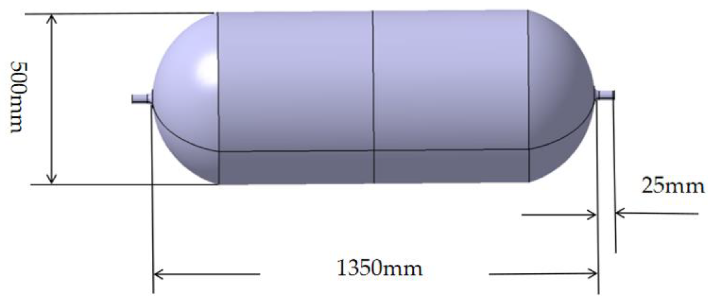
A particular type of hydrogen-powered UAV hydrogen storage tank (illustrated in
Figure 1) is selected as the research object—the storage tank for hydrogen measures 1400 mm in length and 500 mm in diameter. Standard temperature and ultra-high pressure are utilized in the hydrogen storage process. The initial internal pressure of the tank is 70 MPa, the inner wall material is stainless steel, the inner wall thickness measures 10 mm, the outer wall material is a composite material, each layer has a thickness of 0.2 mm, there are 84 layers in total, and the layup order is [0, 45, 90, −45]. The design parameters of the hydrogen storage tank are shown in
Table 1.
2.2. Structural Material Composition of Hydrogen Storage Tank for Hydrogen-Powered UAV
The inner wall material of the hydrogen storage structure is 304 stainless steel, and its mechanical properties are shown in
Table 2.
The outer wall material of the hydrogen storage structure is T800 composite material, and its mechanical properties are shown in
Table 3.
3. Hydrogen Storage Structure Modeling Scheme of Hydrogen Powered UAV
3.1. Finite Element Mesh
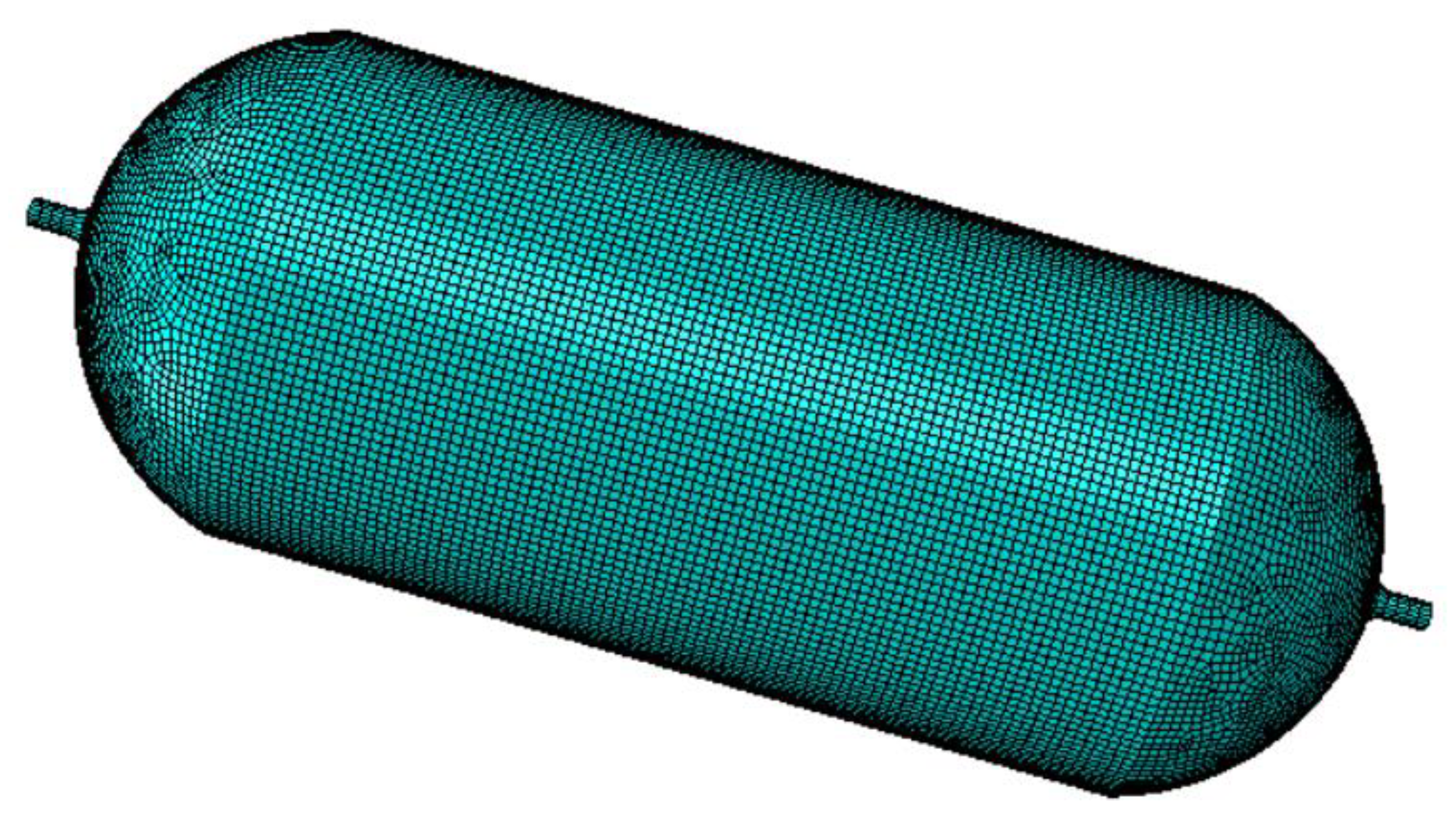
As illustrated in
Figure 2, the hydrogen-powered UAV features a meshed hydrogen storage structure. A quadrilateral shell element (S4R) is used for subdivision (the triangular shell element S3 is utilized partially on both sides of the tank), and the mesh size is 10 mm. The structure comprises 22,087 units, encompassing 21,841 quadrilateral shell elements and 246 triangular shell elements.
3.2. Material Damage Criteria
304 stainless steel adopts the JC damage criterion, and the specific setting parameters are shown in
Table 4 and
Table 5.
To define failure within the ply, Hashin–Rotem failure parameters were implemented. Hashin–Rotem failure is the standard approach for modeling material failure in composites within Abaqus. The four modes of failure are fiber compression, fiber tension, matrix compression, and matrix tension. Shear failure contributes to matrix tension or compression failure but is not defined as an individual failure mode within Abaqus. The material failure initiation is based on an effective stress tensor
, shown in Equation (1), which accounts for damage to the material. M is the damage operator, and
σ is the true stress (i.e., the stress the actual structure would experience). In the description of the damage operator in Equation (2),
df,
dm, and
ds are the damage variables for fiber, matrix, and shear. If all damage variables have a value of 0, corresponding to no damage initiation, the effective stress would equal the true stress. As a composite laminate undergoes damage, softening occurs, and there would be less material to resist the internal forces. Failure in one mode would significantly influence the other failure modes, which is accounted for in the damage operator. Abaqus uses the damage operator to artificially increases the stress used to determine the failure initiation for each mode based on whether failure initiation has been met in other modes [
13,
14,
15].
The stress indicates the effective stress in the longitudinal direction of the ply (i.e., fiber direction in the tape material), is the effective stress component in the transverse direction of the ply, and is the in-plane effective shear stress within the ply. The following equations define the failure initiation:
Fiber tension
Fiber compression
Matrix tension
Matrix compression
Hashin–Rotem (1973):
Hashin (1980): α = 1,
XT longitudinal tensile strength;
XC longitudinal compressive strength;
YT transverse tensile strength;
YC transverse compressive strength;
SC longitudinal shear strength (1–2 direction);
ST transverse shear strength (2–3 direction);
α coefficient that determines the contribution of the shear stress to the fiber tensile initiation criterion.
Parameters of the Hashin damage criterion equation for T800 composites are shown in
Table 6.
3.3. The Finite Element Method Setup
After the modeling of the hydrogen storage structure is completed, the structure and the ground are assembled, and the bottom of the ground is fixed. Adjust the positional relationship between the hydrogen storage structure and the ground, enter the corresponding load cases, and then use Abaqus/Explicit to solve the impact problem. The simulation time is 0.003 s, the time step is 5% of the simulation time, and the deformation scale factor is 1.
4. Explicit Finite Element Analysis of Hydrogen Storage Structure for Hydrogen-Powered UAV Crash Impact
4.1. Impact Analysis of Impact Angle
This section examines the time at which the hydrogen storage structure of the hydrogen-powered UAV impacts the ground at 0°, 15°, 30°, 45°, 60°, and 90° with an internal pressure of 70 MPa and 80 mph (the average crash speed of the UAV) to analyze the impact of the impact angle on the impact dynamic response.
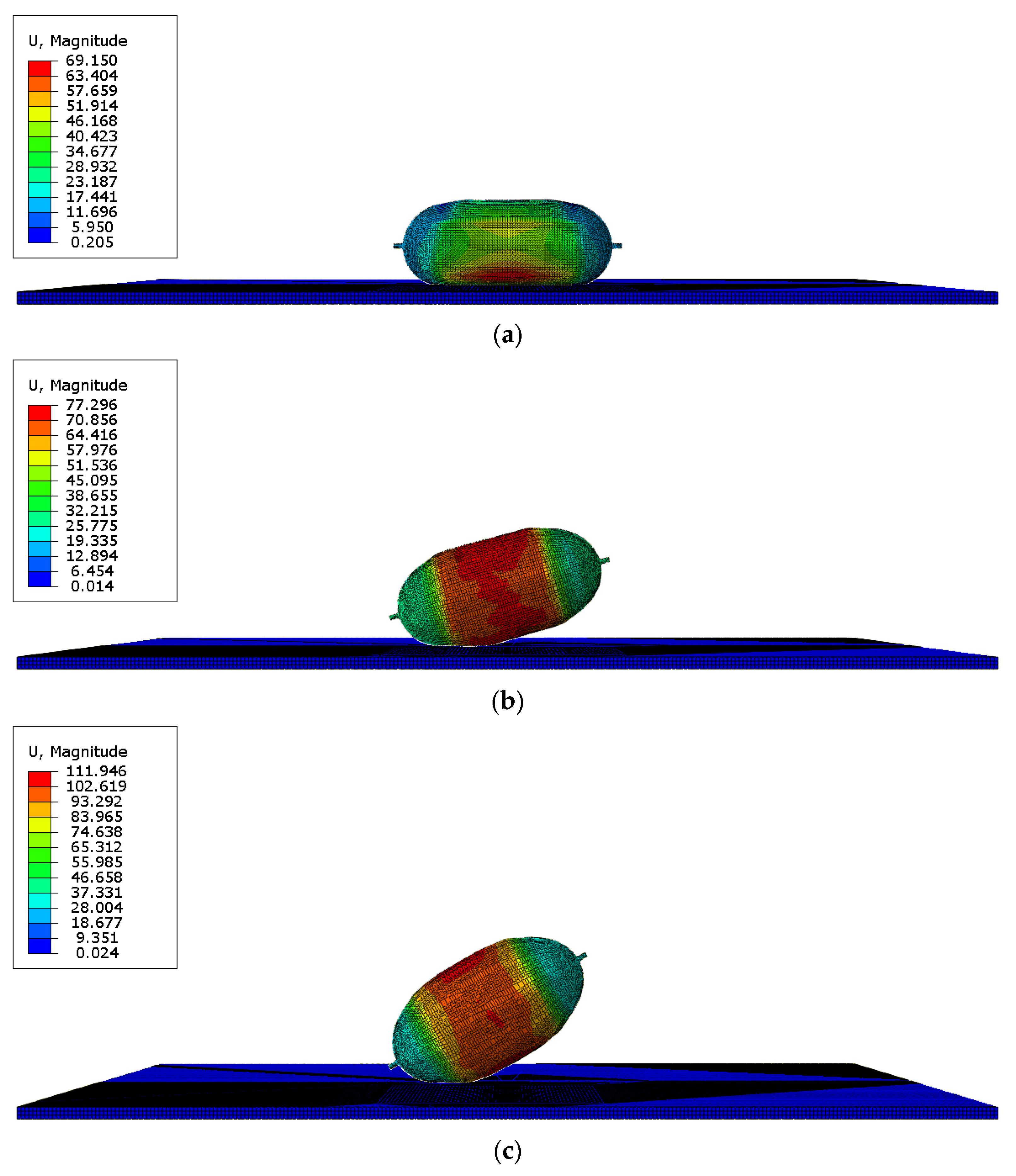
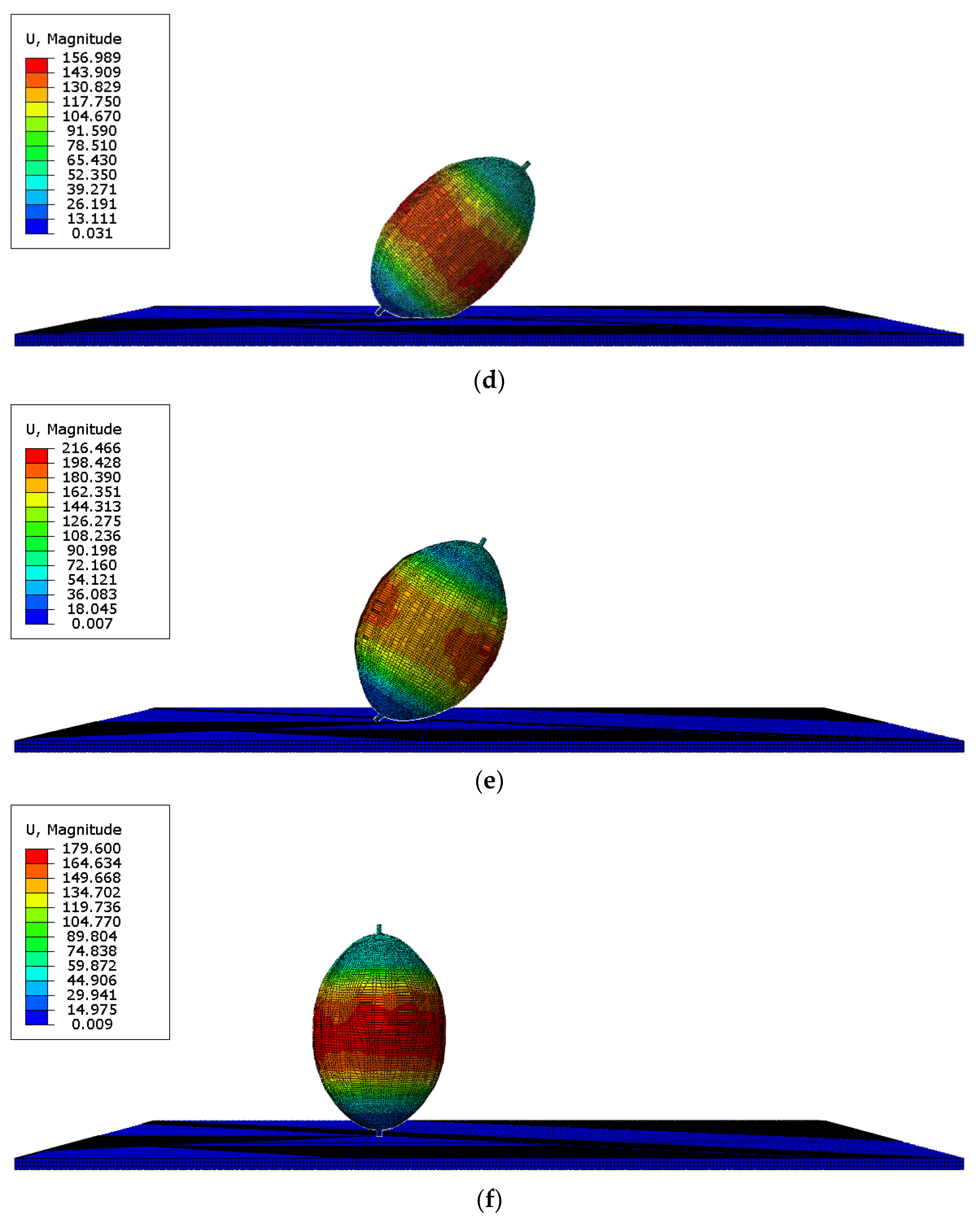
Table 7 demonstrates that as the impact angle increases, the time of the appearance of the initial crack will be delayed, and the location of the initial cracks will be changed.
Figure 3 shows the deformation of the hydrogen storage structure at the initial crack time under different impact angles.
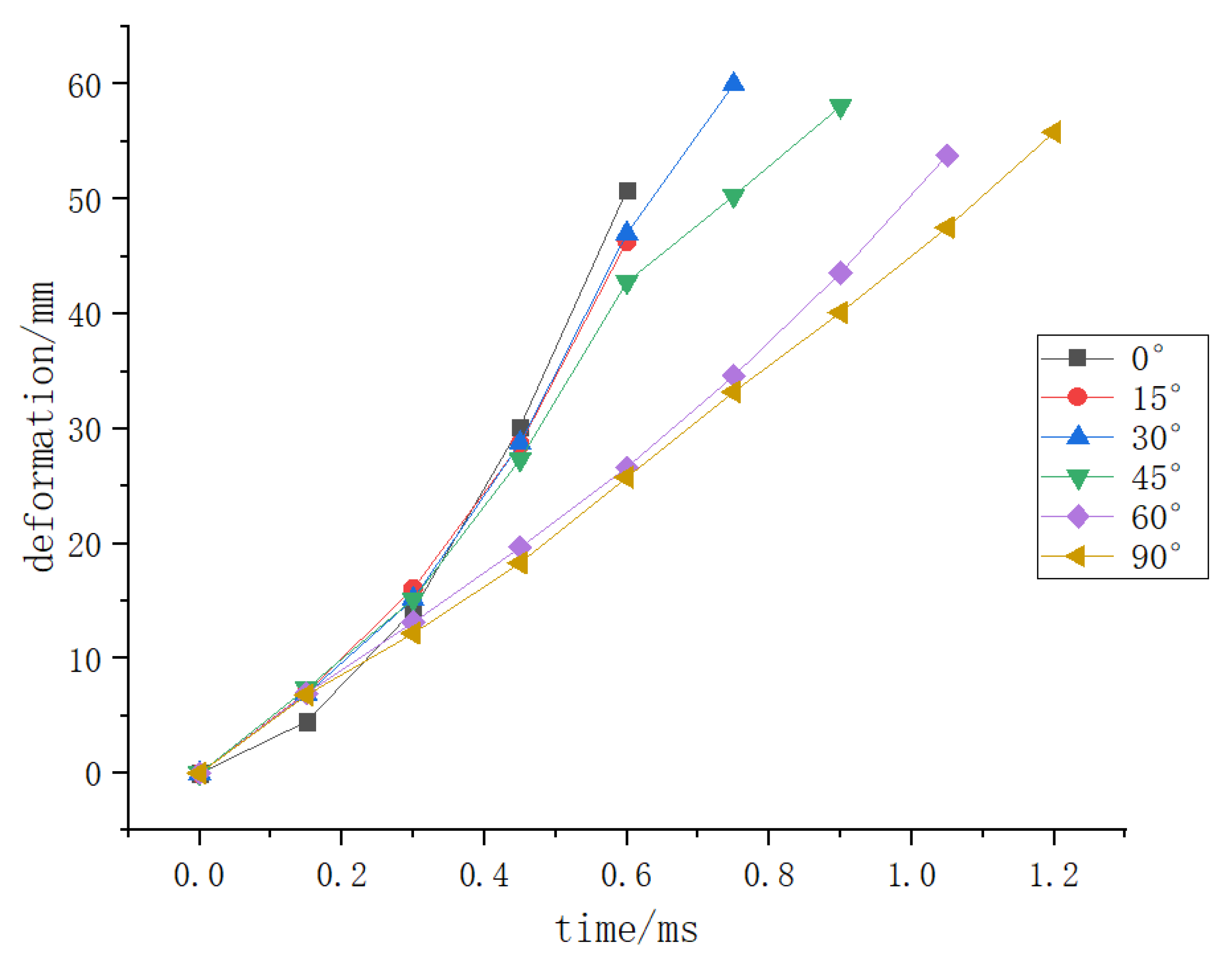
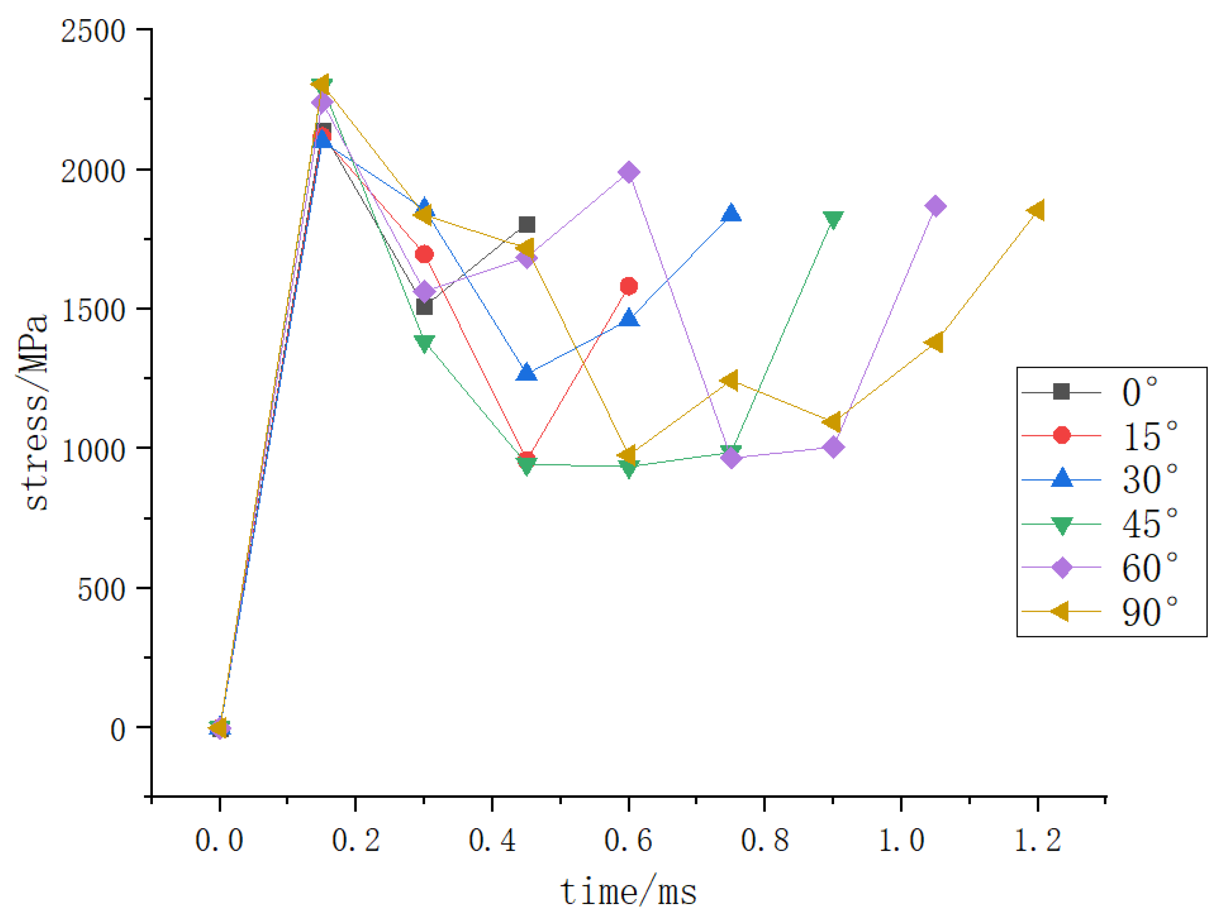
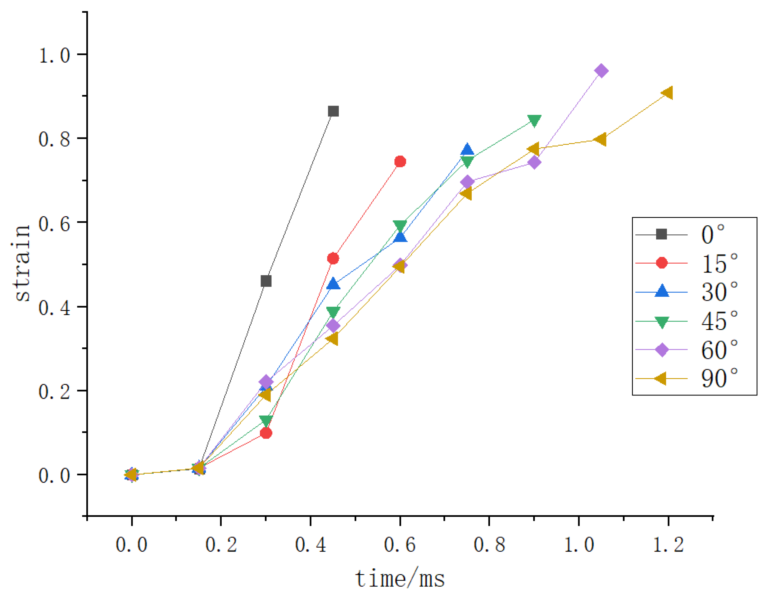
Based on the time when the initial crack occurs, the data of the deformation, stress, and strain of the hydrogen storage structure where the initial crack occurs with time under different load conditions shall be counted and integrated into the following curve.
Figure 4,
Figure 5 and
Figure 6 show that when the deformation of the hydrogen storage structure exceeds 50 mm and the strain exceeds 0.8, the initial crack will appear at this part of the hydrogen storage structure. At the same time, the stress at this part will decrease significantly before the initial crack occurs, and it will be stable at 1850 MPa when the initial crack occurs.
4.2. Analysis of the Influence of Internal Pressure
To examine the effect of the impact angle on the impact dynamic response, this section investigates the impact of a hydrogen storage structure on the ground under three conditions of 80 mph, 0°, 15°, 30°, 45°, 60°, and 90°, and internal pressures of 70 MPa, 50 MPa, and 30 MPa. The four attitudes of 30°, 45°, 60°, and 90° share commonalities with the dynamic responses at 0° and 15°, hence only the dynamic responses at 0° and 15° are selected for analysis.
Table 8 demonstrates that as the internal pressure reduces, the time for the initial crack to appear will be delayed, and the location of the initial cracks will be changed.
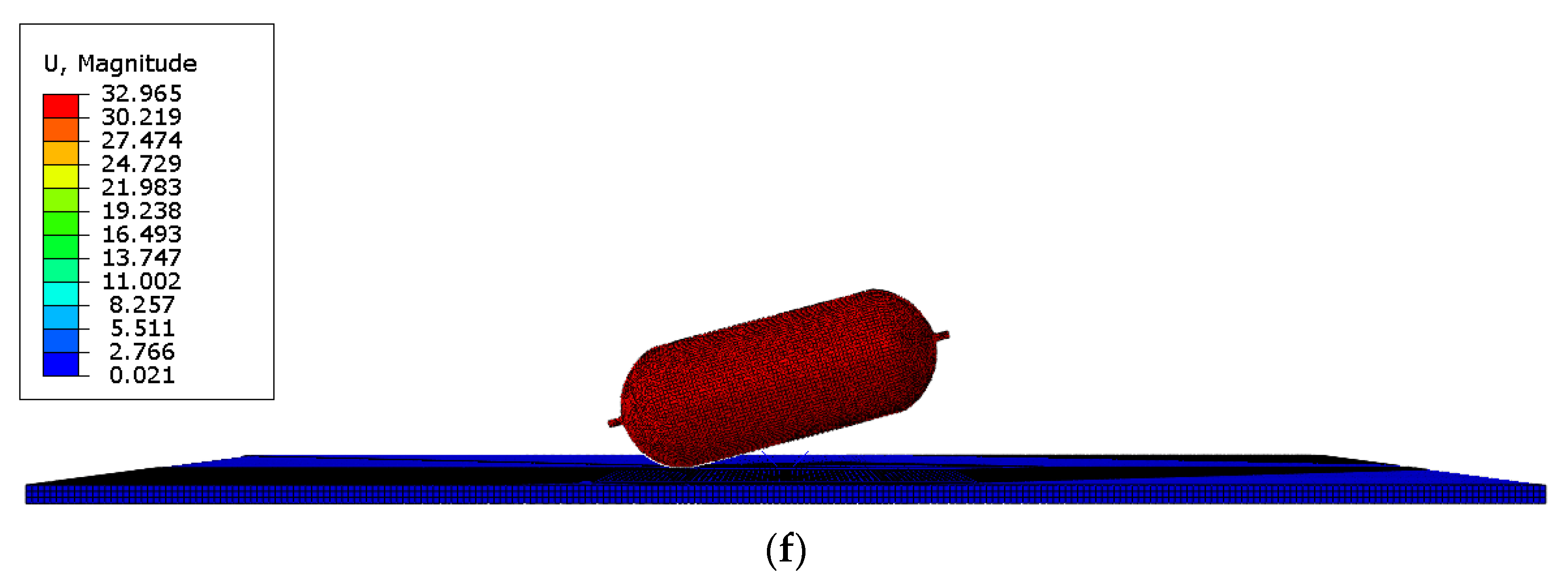
Figure 7 shows the deformation of the hydrogen storage structure at the initial crack time under different internal pressure.
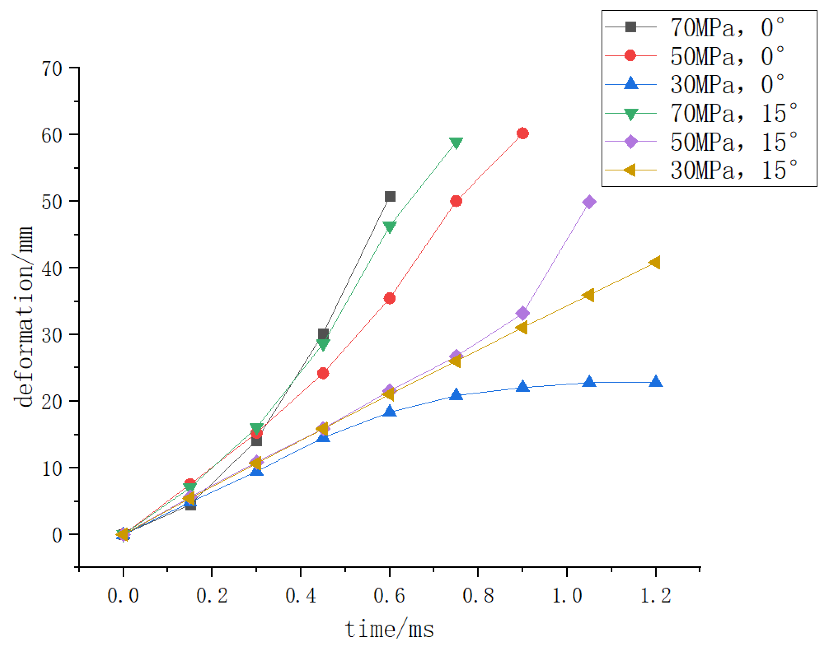
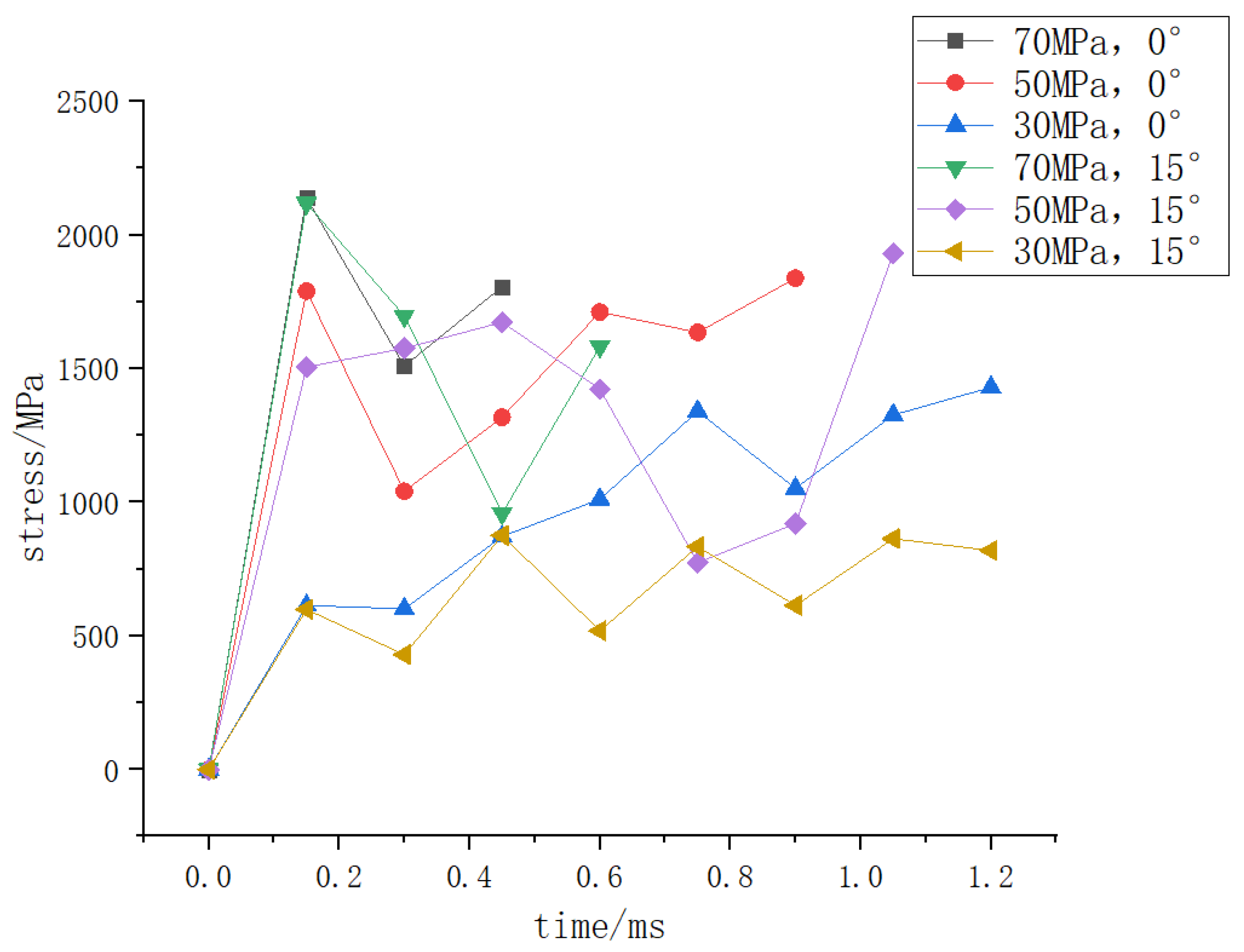
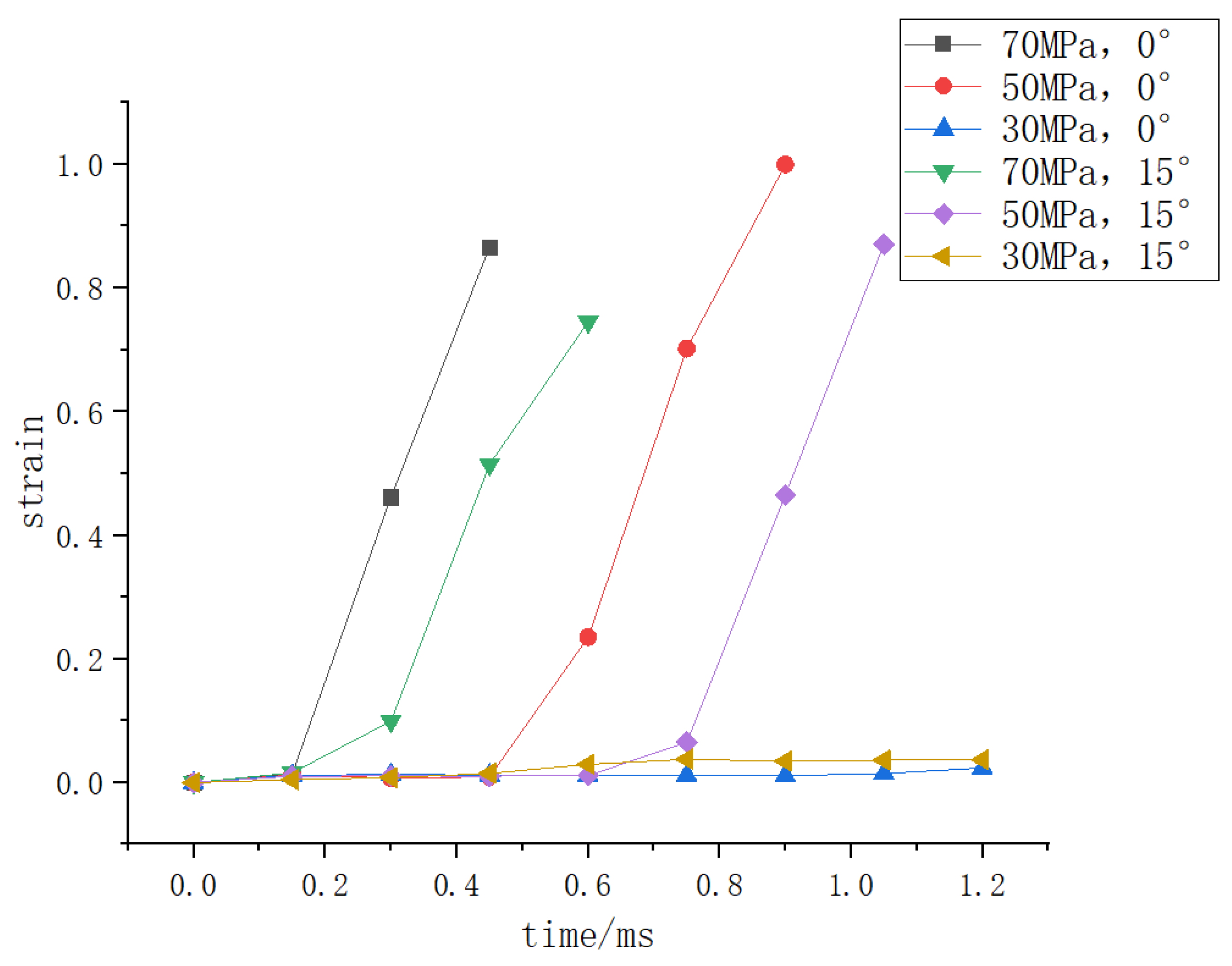
Based on the time when the initial crack occurs, the data of the deformation, stress, and strain of the hydrogen storage structure where the initial crack occurs with time under different load conditions shall be counted and integrated into the following curve.
Figure 8,
Figure 9 and
Figure 10 show that when the deformation of the hydrogen storage structure exceeds 50 mm and the strain exceeds 0.8, the initial crack will appear at this part of the hydrogen storage structure. At the same time, the stress at this part will decrease significantly before the initial crack occurs, and it will be stable at 1850 MPa when the initial crack occurs, but when the deformation does not exceed 50 mm or the strain does not exceed 0.8, the hydrogen storage structure will not have initial cracks.
4.3. Impact Analysis of Speed
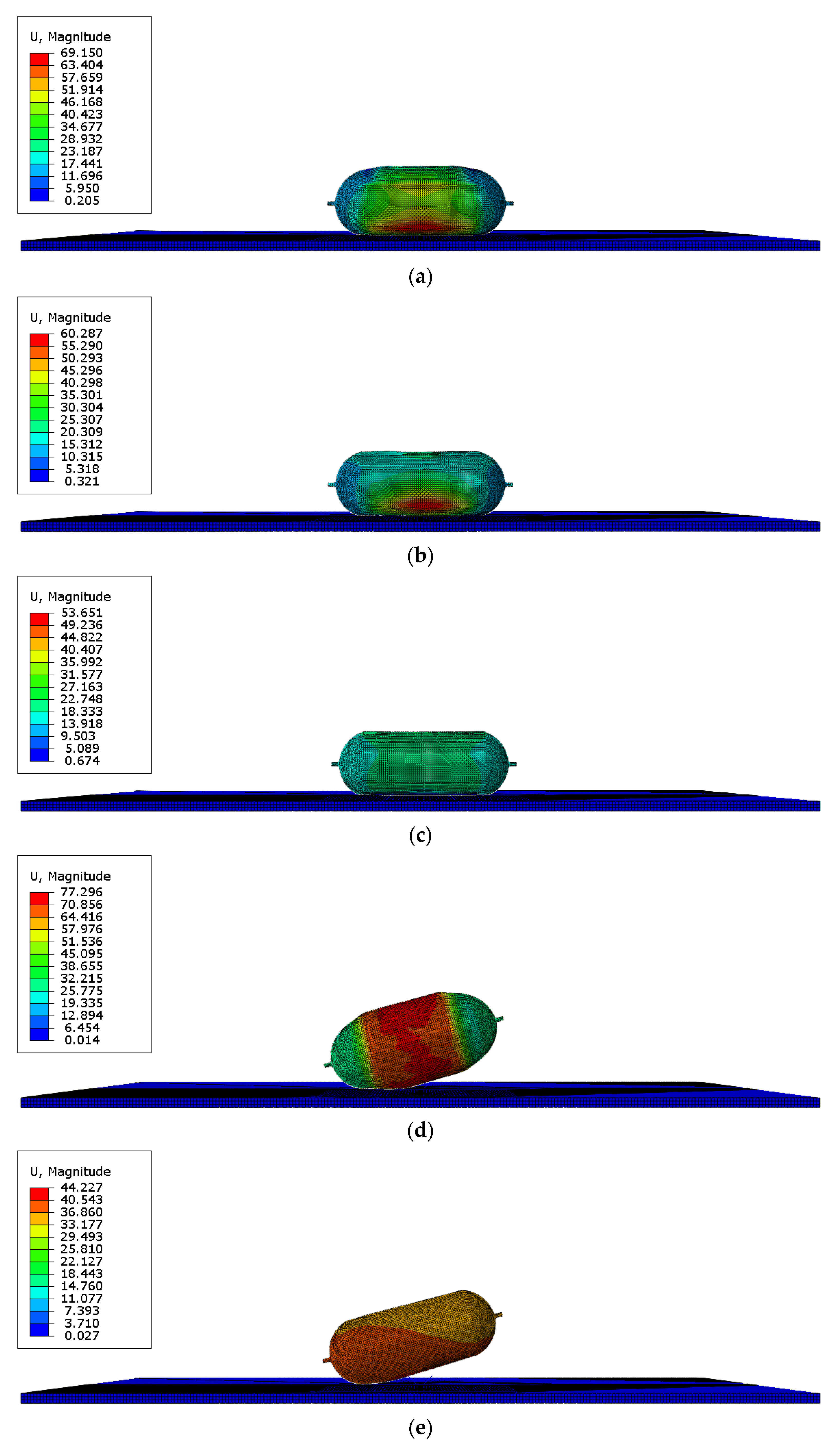
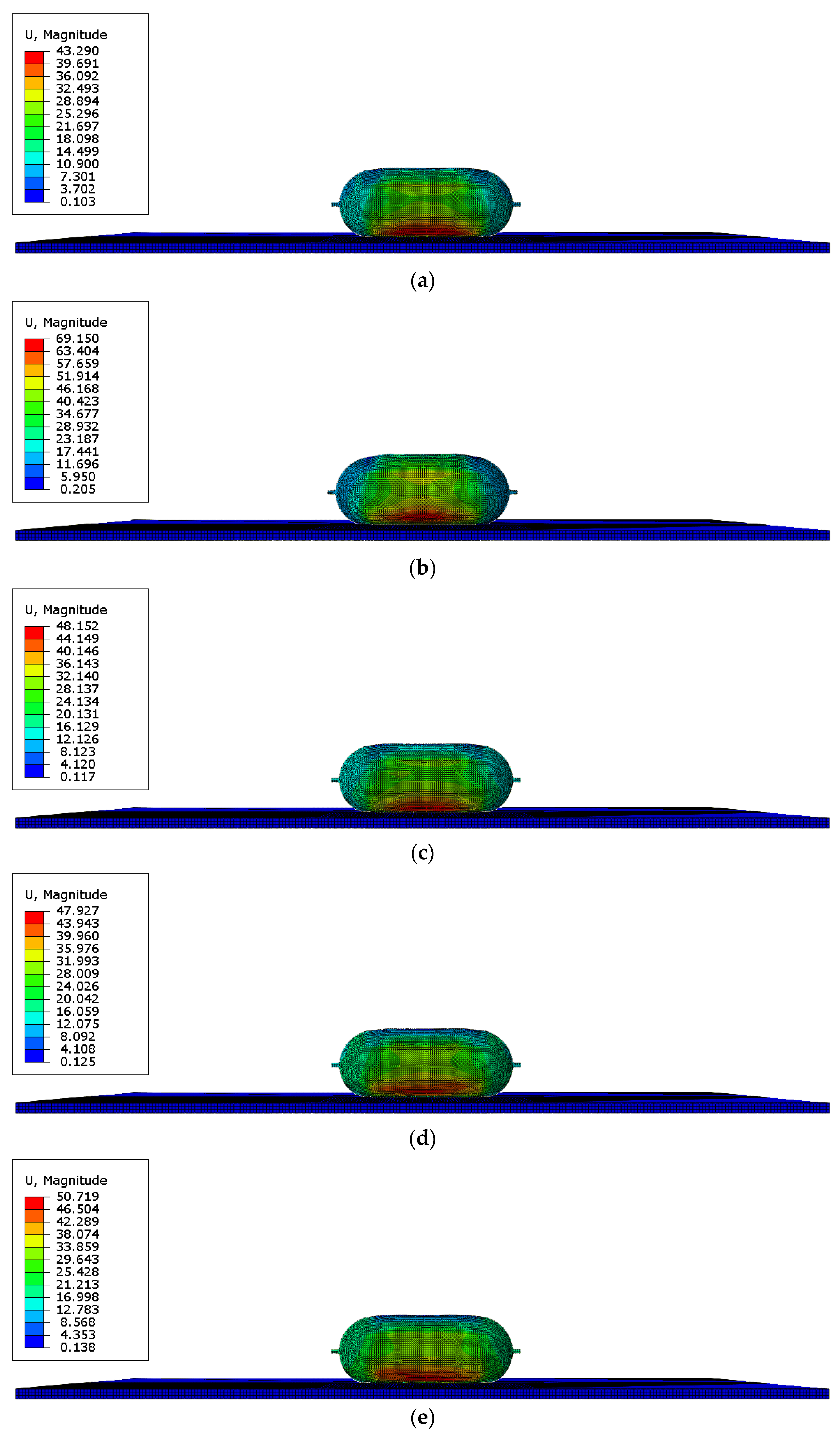
This section analyzes the effect of impact velocity on the impact dynamics response by examining the impact dynamics response of the hydrogen storage tank on the ground at 70 mph, 80 mph, 90 mph, 100 mph, and 120 mph with an internal pressure of 70 MPa and 0° attitude.
Figure 11 demonstrates that the change in impact velocity has no obvious effect on the time and location of the initial crack.
The deformation, stress, and strain trends of the hydrogen storage structure are similar to those in the previous two sections, which will not be repeated here.
4.4. Summary
Summarizing the contents of the first three subsections, it can be seen that when the deformation of the hydrogen storage structure exceeds 50 mm and the strain exceeds 0.8, the initial crack will appear at this part of the hydrogen storage structure. At the same time, the stress at this part will decrease significantly before the initial crack occurs, and it will be stable at 1850 MPa when the initial crack occurs, but when the deformation does not exceed 50 mm or the strain does not exceed 0.8, the hydrogen storage structure will not have initial cracks. The change of impact angle and internal pressure have an obvious effect on the time and location of the initial crack, but not speed.
5. Conclusions
(1) A finite element model was developed with a particular type of hydrogen-powered Unmanned Aerial Vehicle (UAV) as the subject.
(2) A series of crash characteristics analyses of the hydrogen storage structure of a hydrogen-powered UAV were conducted, and the FEA response of the structure under different impact angles, tank internal pressures, and impact speeds were obtained and analyzed. When the deformation of the hydrogen storage structure exceeds 50 mm, and the strain exceeds 0.8, the initial crack will appear at this part of the hydrogen storage structure. At this time, the emergency release valve should respond immediately to release the gas inside the tank to avoid further damage.
(3) Impact angle, and initial internal pressure are the main factors affecting the formation of initial cracks.
(4) After integrating the finite element responses of the structure under different impact angles, different tank pressures, and different impact velocities, we found that the initial cracks of the tank body under various load conditions are mostly concentrated in the middle of the tank body. Therefore, in the future design of similar hydrogen storage structures, strengthening the middle of the tank body will be a point that must be considered. At the same time, we found the changing trend of deformation, stress, and strain on the tank body before the initial crack appeared, which provided a reference for the future opening conditions of emergency release valves of similar hydrogen storage structures. In general, this paper provides guiding suggestions for the future structure design of similar hydrogen storage tanks and provides direction and improvement measures for the design of aviation hydrogen storage tanks.
Author Contributions
Conceptualization, Y.Z. and S.W.; methodology, Y.Z. and S.W.; software, S.W. and B.C.; validation, S.W.; formal analysis, Y.Z., S.W. and B.C.; investigation, S.W., B.C. and N.Z.; resources, B.C. and N.Z.; data curation, S.W. and N.Z.; writing—original draft preparation, Y.Z. and S.W.; writing—review and editing, Y.Z., S.W., and B.C.; visualization, S.W. and B.C.; supervision, Y.Z.; project administration, Y.Z.; funding acquisition, Y.Z. All authors have read and agreed to the published version of the manuscript.
Funding
This research was funded by the National Natural Science Foundation of China (Grant Nos. 11972301, 11201375, 11972300), the Natural Science Foundation of Shaanxi Province (Grant No. 2018JQ1071), State Key Laboratory of Structural Analysis for Industrial Equipment (China) (Grant No. GZ18107) and the Fundamental Research Funds for the Central Universities of China (Grant No. G2019KY05203).
Data Availability Statement
Not applicable.
Conflicts of Interest
The authors declare no conflict of interest.
References
- Roh, H.; Hua, T.; Ahluwalia, R. Optimization of carbon fiber usage in Type 4 hydrogen storage tanks for fuel cell automobiles. Int. J. Hydrogen Energy 2013, 38, 12795–12802. [Google Scholar] [CrossRef]
- Alcántar, V.; Aceves, S.; Ledesma, E.; Ledesma, S.; Aguilera, E. Optimization of Type 4 composite pressure vessels using genetic algorithms and simulated annealing. Int. J. Hydrogen Energy 2017, 42, 15770–15781. [Google Scholar] [CrossRef]
- Son, D.-S.; Chang, S.-H. Evaluation of modeling techniques for a type III hydrogen pressure vessel (70MPa) made of an aluminum liner and a thick carbon/epoxy composite for fuel cell vehicles. Int. J. Hydrogen Energy 2012, 37, 2353–2369. [Google Scholar] [CrossRef]
- Ramirez, J.P.B.; Haltn, D.; Grandidier, J.-C.; Villalonga, S. A fixed directions damage model for composite materials dedicated to hyperbaric type IV hydrogen storage vessel-Part I: Model formulation and identification. Int. J. Hydrogen Energy 2015, 40, 13165–13173. [Google Scholar] [CrossRef]
- Aceves, S.M.; Berry, G.D.; Martinez-Frias, J.; Espinosa-Loza, F. Vehicular storage of hydrogen in insulated pressure vessels. Int. J. Hydrogen Energy 2006, 31, 2274–2283. [Google Scholar] [CrossRef]
- Chung, C.; Yang, S.-W.; Yang, C.-Y.; Hsu, C.W.; Chiu, P.Y. Experimental study on the hydrogen charge and discharge rates of metal hydride tanks using heat pipes to enhance heat transfer. Appl. Energy 2013, 103, 581–587. [Google Scholar] [CrossRef]
- Veluswamy, H.P.; Kumar, R.; Linga, P. Hydrogen storage in clathrate hydrates: Current state of the art and future directions. Appl. Energy 2014, 122, 112–132. [Google Scholar] [CrossRef]
- He, C.; Yu, R.; Sun, H.; Chen, Z. Lightweight multilayer composite structure for hydrogen storage tank. Int. J. Hydrogen Energy 2016, 41, 15812–15816. [Google Scholar] [CrossRef]
- De Wagter, C.; Remes, B.; Smeur, E.; van Tienen, F.; Ruijsink, R.; van Hecke, K.; van der Horst, E. The NederDrone: A hybrid lift, hybrid energy hydrogen UAV. Int. J. Hydrogen Energy 2021, 46, 16003–16018. [Google Scholar] [CrossRef]
- Fowler, C.P.; Orifici, A.C.; Wang, C.H. A review of toroidal composite pressure vessel optimisation and damage tolerant design for high pressure gaseous fuel storage. Int. J. Hydrogen Energy 2016, 41, 22067–22089. [Google Scholar] [CrossRef]
- Li, J.C.; Chen, X.W.; Huang, F.L. FEM analysis on the deformation and failure of fiber reinforced metallic glass matrix composite. Mater. Sci. Eng. A 2016, 652, 145–166. [Google Scholar] [CrossRef]
- Li, G.L.; Peng, G.Q.; Zhong, X.Y. Characterization of domestic high performance carbon fibers and mechanical properties of carbon fibers reinforced matrix composites. J. Mater. Eng. 2020, 48, 74–81. [Google Scholar]
- Hashin, Z.; Rotem, A. A fatigue failure criterion for fiber reinforced materials. J. Compos. Mater. 1973, 7, 448–464. [Google Scholar] [CrossRef]
- Takeuchi, F.; Kawai, M.; Zhang, J.-Q.; Matsuda, T. Rate-dependence of off-axis tensile behavior of cross-ply: CFRP laminates at elevated temperature and its simulation. Adv. Compos. Mater. 2008, 17, 57–73. [Google Scholar] [CrossRef][Green Version]
- López-Puente, J.; Li, S. Analysis of strain rate sensitivity of carbon/epoxy woven composites. Int. J. Impact Eng. 2012, 48, 54–64. [Google Scholar] [CrossRef]
Figure 1.
Structure of composite hydrogen storage tank.
Figure 1.
Structure of composite hydrogen storage tank.
Figure 2.
Hydrogen storage structure grid diagram.
Figure 2.
Hydrogen storage structure grid diagram.
Figure 3.
The time when the initial crack occurs in the hydrogen storage structure under different impact angles (units for quantities on figures are mm). (a) t = 0.45 ms (initial cracks appear, 0°); (b) t = 0.6 ms (initial cracks appear, 15°); (c) t = 0.75 ms (initial cracks appear, 30°); (d) t = 0.9 ms (initial cracks appear, 45°); (e) t = 1.05 ms (initial cracks appear, 60°); (f) t = 1.20 ms (initial cracks appear, 90°).
Figure 4.
The deformation of the hydrogen storage structure where the initial crack occurs with time under different impact angles.
Figure 4.
The deformation of the hydrogen storage structure where the initial crack occurs with time under different impact angles.
Figure 5.
The stress of the hydrogen storage structure where the initial crack occurs with time under different impact angles.
Figure 5.
The stress of the hydrogen storage structure where the initial crack occurs with time under different impact angles.
Figure 6.
The strain of the hydrogen storage structure where the initial crack occurs with time under different impact angles.
Figure 6.
The strain of the hydrogen storage structure where the initial crack occurs with time under different impact angles.
Figure 7.
The time when an initial crack occurs in the hydrogen storage structure under different internal pressure (units for quantities on figures are mm). (a) t = 0.45 ms (initial cracks appear, 70 MPa, 0°); (b) t = 0.9 ms (initial cracks appear, 50 MPa, 0°); (c) t = 1.5 ms (no initial cracks appear, 30 MPa, 0°); (d) t = 0.75 ms (initial cracks appear, 70 MPa, 15°); (e) t = 1.05 ms (initial cracks appear, 50 MPa, 15°); (f) t = 1.5 ms (no initial cracks appear, 30 MPa, 15°).
Figure 8.
The deformation of the hydrogen storage structure where the initial crack occurs with time under different internal pressure.
Figure 8.
The deformation of the hydrogen storage structure where the initial crack occurs with time under different internal pressure.
Figure 9.
The stress of the hydrogen storage structure where the initial crack occurs with time under different internal pressure.
Figure 9.
The stress of the hydrogen storage structure where the initial crack occurs with time under different internal pressure.
Figure 10.
The strain of the hydrogen storage structure where the initial crack occurs with time under different internal pressure.
Figure 10.
The strain of the hydrogen storage structure where the initial crack occurs with time under different internal pressure.
Figure 11.
The time when an initial crack occurs in the hydrogen storage structure under different speeds (units for quantities on figures are mm). (a) t = 0.45 ms (initial cracks appear, 70 mph); (b) t = 0.45 ms (initial cracks appear, 80 mph); (c) t = 0.45 ms (initial cracks appear, 90 mph); (d) t = 0.45 ms (initial cracks appear, 100 mph); (e) t = 0.45 ms (initial cracks appear, 120 mph).
Table 1.
Design parameters of the hydrogen storage structure.
Table 1.
Design parameters of the hydrogen storage structure.
| Length/mm | Diameter/mm | Volume/m3 | Stored Hydrogen Mass/kg | Initial Internal Pressure/MPa |
|---|
| 1400 | 500 | 0.23 | 10 | 70 |
Table 2.
304 stainless steel material properties [
11].
Table 2.
304 stainless steel material properties [
11].
| Density/kg/m3 | Young’s Modulus/GPa | Poisson’s Ratio |
|---|
| 7900 | 190 | 0.29 |
Table 3.
T800 composite properties [
12].
Table 3.
T800 composite properties [
12].
| | | | | | | | |
|---|
| 145.21 | 10.01 | 10.01 | 0.35 | 0.33 | 0.33 | 6.79 | 6.79 | 5.71 |
Table 4.
Parameters of 304 stainless steel JC constitutive equation [
11].
Table 4.
Parameters of 304 stainless steel JC constitutive equation [
11].
| A/MPa | B/MPa | C | n | m | Strain Rate |
|---|
| 463 | 426 | 0.015 | 0.25 | 1.03 | 1 |
Table 5.
Parameters of 304 stainless steel JC damage criterion equation [
11].
Table 5.
Parameters of 304 stainless steel JC damage criterion equation [
11].
Table 6.
Parameters of the Hashin damage criterion equation for T800 composites [
12].
Table 6.
Parameters of the Hashin damage criterion equation for T800 composites [
12].
| XT/MPA | XC/MPA | YT/MPA | YC/MPA | SC/MPA | ST/MPA |
|---|
| 2405 | 1800 | 65.3 | 250 | 104 | 104 |
Table 7.
Responses of hydrogen storage structures at different impact angles.
Table 7.
Responses of hydrogen storage structures at different impact angles.
| Impact Angle | Time of the Initial Crack Appearance (ms) | Location of the Initial Crack Appearance | Destruction Mode |
|---|
| 0° | 0.45 | Top of the middle of the tank | Matrix Tension and Shear Failure |
| 15° | 0.75 | Top and both sides of the middle of the tank | Matrix Tension and Shear Failure |
| 30° | 0.9 | Both sides of the middle of the tank | Matrix Tension and Shear Failure |
| 45° | 1.05 | Both sides of the middle of the tank | Matrix Tension and Shear Failure |
| 60° | 1.2 | Both sides of the middle of the tank | Matrix Tension and Shear Failure |
| 90° | 1.2 | Both sides of the middle of the tank | Matrix Tension and Shear Failure |
Table 8.
Responses of hydrogen storage structures at different internal pressure.
Table 8.
Responses of hydrogen storage structures at different internal pressure.
| Impact Angle and Internal Pressure | Time of the Initial Crack Appearance (ms) | Location of the Initial Crack Appearance | Overall Destruction Mode |
|---|
| 0°, 70 MPa | 0.45 | Top of the middle of the tank | Matrix Tension and Shear Failure |
| 0°, 50 MPa | 0.9 | Top of the middle of the tank | Matrix Tension and Shear Failure |
| 0°, 30 MPa | No initial cracks appear | No initial cracks appear | No overall damage occurred |
| 15°, 70 MPa | 0.75 | Top and both sides of the middle of the tank | Matrix Tension and Shear Failure |
| 15°, 50 MPa | 1.05 | Bottom of the middle of the tank
(near the collision position) | Matrix Tension and Shear Failure |
| 15°, 30 MPa | No initial cracks appear | No initial cracks appear | No overall damage occurred |
| Publisher’s Note: MDPI stays neutral with regard to jurisdictional claims in published maps and institutional affiliations. |
© 2022 by the authors. Licensee MDPI, Basel, Switzerland. This article is an open access article distributed under the terms and conditions of the Creative Commons Attribution (CC BY) license (https://creativecommons.org/licenses/by/4.0/).
