Abstract
The Co-Flow Jet (CFJ) technique is an effective way to enhance the aerodynamics of airfoils. The present study is to comprehensively investigate the effects of CFJ key parameters, viz., the jet momentum coefficient, the injection slot location, the injection slot size, the suction slot location, the suction slot size, and the suction slot angle, on the airfoil aerodynamic characteristics based on the numerical method of Reynolds Averaged Navier-Stokes (RANS) equations coupled with the Spalart-Allmaras (S-A) turbulence model. The numerical method is validated by a CFJ6415 airfoil case, and a relatively good agreement with the experiment is achieved. The results show that a larger jet momentum coefficient is more conducive to lift enhancement, drag reduction, and stall margin enlargement. However, a relatively smaller jet momentum coefficient could increase the corrected aerodynamic efficiency at small angles of attack. The variation of the injection slot location is barely influential to the lift coefficient. With the increase of the injection slot size, the power coefficient first decreases and then increases, and the corrected aerodynamic efficiency first increases and then decreases. The drag coefficient increases monotonously as the suction slot location moves downstream. Furthermore, a relatively smaller suction slot size or a larger suction slot angle could better reduce the drag and enhance the CFJ airfoil aerodynamics.
1. Introduction
The rapid development of aerospace science accelerates the pursuit of new technologies to achieve revolutionary aircraft performance, among which flow control is considered a promising means to significantly improve aerodynamic characteristics [1,2]. The flow control makes it possible to dramatically reduce aircraft weight and fuel consumption, and to enhance aircraft maneuverability. Therefore, it will play an important role in the foreseeable future.
Flow control can be commonly divided into passive flow control and active flow control. The passive flow control methods are dedicated to affecting the pressure gradient, increasing the mixing and energizing the boundary layer by geometrical shapes or structures, including vortex generators [3], winglets [4], Leading Edge (LE) slat [5], multi-section wing [6], shock control bump [7], etc. However, with the increasing maturity of airfoil design methods, it is difficult to achieve aerodynamic performance enhancement solely by shape design.
Active flow control has attracted more and more attention in the field of aircraft design because of its adjustability and flexibility. It transfers the external energy into the controlled flow to improve the aerodynamic characteristics. The active flow control usually includes the Circulation Control (CC) [8,9,10], the synthetic jet [11,12], the plasma jet [13,14], the Co-Flow Jet (CFJ) [15,16], etc. The principle of CC is based on the Coanda effect, which means the tendency of the jet flow to follow a convex surface without separation while additionally entraining fluid from surroundings [8]. Min et al. [9] studied the influence of turbulence models and spatial accuracy on CC airfoils. Xu et al. [10] applied the CC to a wind turbine airfoil with a blunt Trailing Edge (TE), and they found that CC could significantly improve the lift and reduce the drag. In addition, a larger slot size was conducive to the control efficiency of CC. However, the thick TE of the CC airfoil leads to additional drag, which blocks the aerodynamic performance enhancement. Furthermore, CC dumps the jet mass flow, which is negative for the propulsion system [15]. The synthetic jet and the plasma jet exploit the actuators to generate active jet flow and suppress the flow separation. These approaches avoid dumping the jet mass flow, therefore they could achieve the Zero-Net Mass Flux (ZNMF). However, the interaction between these jets and the mainstream is weak, and their control effects and mechanisms need to be further explored [16].
The CFJ concept was first proposed by Zha and Paxton [17]. The CFJ opens an injection slot near the LE and a suction slot near the TE of the airfoil suction surface, with a pumping system, mounted inside the wing to withdraw, energize and inject the airflow. The whole process ensures the conservation of the mass flow, thus it is also a ZNMF control method. The mechanism of the CFJ is to introduce energy into the boundary layer by the turbulent mixing between the jet flow and the main flow. Comprehensive investigations have been conducted on the CFJ stationary airfoils by means of wind tunnel tests and Computational Fluid Dynamics (CFD) calculations. For wind tunnel tests, Zha et al. [18] investigated the effect of the injection slot size on its aerodynamics. They pointed out that a smaller injection slot size was more effective to increase the maximum lift and stall margin, while a larger suction slot size was more conducive to reducing the drag. Dano et al. [19] studied the jet mixing of a CFJ airfoil to explore the mechanism of the CFJ technique. They further reported the aerodynamic performance enhancement by Discrete Co-Flow Jet (DCFJ) [20,21]. Zhang et al. [22] conducted an experimental study to examine the DCFJ control effects on a rotor airfoil. For CFD analyses, most of the numerical methods for the CFJ in the existing literature are based on the Reynolds Averaged Navier-Stokes (RANS) equations coupled with the Spalart-Allmaras (S-A) turbulence model [15,23,24,25,26]. Lefebvre et al. [15] investigated the influence of the Mach number variation on the performance and energy expenditure of the CFJ6415 airfoil. The simulation results indicated that the CFJ enabled the airfoil to obtain a higher maximum lift coefficient at small angles of attack. Based on the NACA23121 airfoil, they [23] conducted a trade study to investigate the effects of several CFJ parameters, namely the injection location, the suction size, the suction location, the airfoil thickness, and the Reynolds number. However, the variation range of the parameters studied was relatively small, and only the case at the angle of attack α of 10° was studied. Consequently, the universality of the results should be further verified. Wang et al. [24] numerically studied the Reynolds number effect for a CFJ6421 airfoil and found that a relatively larger Reynolds number was more beneficial to CFJ airfoil aerodynamics. Liu et al. [25] first exploited the CFJ to the RAE2822 supercritical airfoil and demonstrated the feasibility of the CFJ for the transonic regime. Lei et al. [26] innovatively applied the CFJ to a supersonic thin airfoil for the sake of improving the low-speed performance, which could provide support for the design of the supersonic vehicle with a wide-speed range. Furthermore, Wang et al. [27] and Im et al. [28] also adopted the Detached-Eddy Simulation (DES) and the Large-Eddy Simulation (LES) to examine the CFJ airfoil performance at high angles of attack. In addition, the CFJ technique has also been widely used in dynamic stall control [16,29,30], aircraft control surface design [31,32], separation control in serpentine ducts [33,34] and reverse thrust generation [35]. However, there have been few systematic studies on the effects of CFJ key parameters on airfoil aerodynamic performance. In order to further understand the CFJ control effects and influencing factors, such research is necessary.
To tackle the above challenges, in the present study, the CFJ technique is applied to the NACA2412 airfoil to investigate the control effects. The two-dimensional RANS coupled with the S-A turbulence model is utilized to numerically simulate the flow features. The influence of several CFJ key parameters, namely the jet momentum coefficient, the injection slot location, the injection slot size, the suction slot location, the suction slot size, and the suction slot angle, is systematically examined. Finally, some concluding remarks are provided.
The remainder of this paper is organized as follows. Section 2 presents the CFJ model and several important CFJ parameters. Section 3 demonstrates the numerical simulation method, the mesh refinement study, and the CFD validation. In Section 4, the effects of several design parameters on the aerodynamics of the CFJ airfoil are separately investigated. Section 5 provides the conclusions of the present study.
2. Model and Parameters
In this section, the CFJ airfoil model is first described. Then, several important parameters to evaluate the CFJ airfoil aerodynamics are introduced.
2.1. CFJ Model
In the present study, the NACA2412 airfoil serves as the baseline airfoil. The CFJ airfoil concept is implemented by opening an injection slot near the LE and a suction slot near the TE, as shown in Figure 1. Besides, a pumping system is mounted inside the wing to blow the air out of the injection slot and withdraw it from the suction slot, which recirculates the airflow. The whole process requires no additional mass flow, which indicates that the CFJ concept is able to achieve the ZNMF.
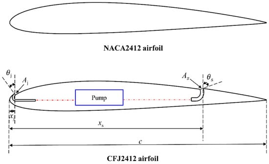
Figure 1.
Schematic diagram of baseline and CFJ airfoils.
Several geometric parameters are commonly exploited to design a CFJ airfoil, namely the injection slot location xj, the injection slot size Aj, the injection slot angle θj, the suction slot location xs, the suction slot size As, and the suction slot angle θs. In this paper, the injection and suction slot locations are initially set to 2%c and 75%c. The injection and suction slot sizes are 0.65%c and 1.3%c respectively, which refers to [15]. Furthermore, the slot angles of the injection and suction are initially 33.4° and 70°.
2.2. CFJ Parameters
This section introduces several CFJ parameters that are crucial to airfoil aerodynamic calculations.
2.2.1. Jet Momentum Coefficient
The jet momentum coefficient Cμ is first employed to measure the jet intensity. It is defined as
in which is the injection mass flow rate; Vj is the mass-averaged injection velocity; ρ∞ is the freestream density; V∞ is the freestream velocity; Sref is the reference area, which equals the chord length c for a 2-D airfoil.
2.2.2. Lift and Drag
The aerodynamic forces of the CFJ airfoil can be divided into three parts: the surface pressure, the surface stress, and the jet reaction forces. The jet reaction forces could be further divided into pressure-induced reaction force and momentum-induced reaction force. The jet reaction forces in the drag and lift directions could be computed from
where is the suction mass flow rate; Vs is the suction mass-averaged velocity; pj and ps are the static pressure in the injection and suction cavities, respectively.
As a result, the lift and drag of the CFJ airfoil could be defined as
where Rx and Ry refer to the surface integral of pressure and shear stress respectively, excluding the internal injection and suction ducts.
2.2.3. Pitching Moment
The CFJ pitching moment could be computed from
where M is pitching moment from the airfoil surface pressure and shear stress excluding the internal injection and suction ducts; Lxinj, Lxsuc, Lyinj, and Lysuc are respectively the moment arms in x and y directions for the injection and suction slots. The moment center is located at (0.25c, 0).
2.2.4. Power Coefficient
Since a pumping system is mounted inside the airfoil to recirculate the airflow from the injection to suction, the CFJ concept requires external energy. The power consumption P could be defined as
in which cp denotes the constant pressure specific heat; Tts is the total pressure in the suction cavity; ptj and pts denote the mass-averaged total pressure in the injection and suction cavities, respectively; γ is the specific heat ratio, which is 1.4 for the air; η denotes the efficiency of the pumping system. According to Xu et al. [36], the typical micro-compressors for aerospace applications could achieve high efficiency of up to 85%. In order to focus on the fluid mechanics of the CFJ technique, η is set to 100% in the present study [34].
The power consumption can be further measured by a power coefficient:
2.2.5. Corrected Aerodynamic Efficiency
Different from the conventional airfoil, the aerodynamic efficiency of CFJ airfoil is no longer measured by L/D due to its requirement for external energy. Therefore, the corrected aerodynamic efficiency Kc could be obtained by converting the power coefficient into a corresponding drag force:
3. Numerical Method and Validation
3.1. Numerical Method
The flow fields around the baseline and CFJ airfoils are solved using the two-dimensional RANS equations, whose integral form could be expressed as
where Q represents conserved variables. FI and FV are inviscid and viscous fluxes. Ω is the control volume and S denotes its boundary.
The adopted numerical method in the present study is based on the Finite Volume Method (FVM). The second-order upwind scheme is used for the spatial discretization of pressure, density, momentum, and energy. The one equation S-A turbulence model is selected to close the N-S equations. The reason is that the S-A turbulence model is very robust and effective in simulating the flow field around an airfoil, with an adverse pressure gradient in the boundary layer [37]. Furthermore, the S-A model has been proven to be well-behaved in most CFJ cases [15,23,24,25,26].
The transport equation [38] of the S-A model can be described as
where the description of each of the terms could be found in [39].
3.2. Computational Mesh and Boundary Conditions
Figure 2 demonstrates the computational mesh and boundary conditions of the CFJ2412 airfoil. An O-type mesh is exploited in the fluid domain to obtain a high-quality grid. Besides, the mesh is refined around the injection and suction slots to capture the local flow characteristics more accurately. The first layer of the airfoil is also refined to guarantee that y+ < 1.
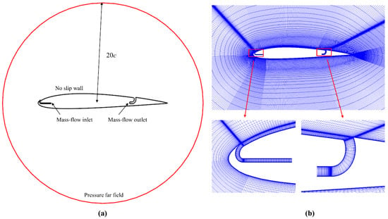
Figure 2.
Computational mesh of the CFJ2412 airfoil. (a) Mesh topology and boundary condition. (b) Computational mesh.
As for the boundary conditions, the domain boundary that locates at 20c is set as the pressure far-field condition. The airfoil surfaces and internal ducts are no-slip solid wall conditions. Mass-flow inlet and mass-flow outlet conditions are exploited inside the injection and suction cavities, respectively. The whole process is to adjust the required mass flow rate iteratively until the specific Cμ is reached within the tolerance of 1%.
3.3. Mesh Refinement Study
Table 1 compares the aerodynamic coefficients of the CFJ2412 airfoil with various grid resolutions at Ma = 0.2, Re = 4.65 × 10⁶, Cμ = 0.06 and α = 10°. It could be observed that the aerodynamic coefficients of the medium mesh are very close to those of the fine mesh, showing great convergence of mesh size. Therefore, the medium mesh with grid number 9.3 × 10⁴ is exploited in the following work.

Table 1.
Aerodynamic coefficients of the CFJ2412 airfoil with various grid resolutions at Ma = 0.2, Re = 4.65 × 10⁶, Cμ = 0.06 and α = 10°.
3.4. Validation
For the purpose of indicating the accuracy of the numerical method in the present study, the CFJ6415 airfoil is selected as the validation. The CFJ6415 airfoil is commonly used as a validation to verify the CFJ calculation accuracy [15]. The simulation condition is set at Ma = 0.03, Re = 2.078 × 10⁵ and Cμ = 0.08. The total cell number is about 1.7 × 10⁵ with the first layer height y+ < 1.
Figure 3 shows the comparison of the lift and drag coefficients for the present CFD simulation, the CFD simulation by Lefebvre et al. [15], and the experimental results [15]. It is obvious that our simulation results show similar trends in comparison to Lefebvre’s CFD simulation and the experimental result. However, it deserves to be pointed out that there exist some differences between the CFD simulations and the experiment, especially at large angles of attack. The reason is that the RANS solver is limited in simulating the large separation flow. In general, it is reliable to exploit the simulation method to estimate aerodynamic coefficients for CFJ airfoils.
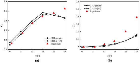
Figure 3.
Comparison of lift and drag coefficients between CFD simulations and the experiment at Ma = 0.03, Re = 2.078 × 10⁵, and Cμ = 0.08 [15]. (a) Lift coefficient. (b) Drag coefficient.
4. Results and Discussions
This section is dedicated to investigating the effects of several CFJ key parameters on the airfoil aerodynamic characteristics, namely the jet momentum coefficient Cμ, the injection slot location xj, the injection slot size Aj, the suction slot location xs, the suction slot size As and the suction slot angle θs. The computational Mach number is 0.2 and the Reynolds number is 4.65 × 10⁶. In this section, the baseline airfoil is equivalent to the case where all CFJ geometric parameters are 0.
4.1. Effect of Jet Momentum Coefficient
Figure 4 depicts the aerodynamic performance of CFJ2412 airfoil with various Cμ values, where three jet momentum coefficients of Cμ = 0.06, 0.09, and 0.12 are selected. It is obvious that the CFJ could significantly increase the lift coefficient compared with the baseline for the cases of Cμ = 0.09 and 0.12. When Cμ = 0.06, the CFJ increases the lift coefficient at small angles of attack, with an enhancement of 12.8% in comparison to the baseline at α = 10°. It could also be observed that the increase of Cμ could lead to a larger lift. The reason is that a larger Cμ could bring higher acceleration on the suction surface, resulting in the increment of the airfoil circulation. For the stall characteristics, the increment of Cμ increases the stall margin. Besides, compared with the baseline, the case of Cμ = 0.12 increases the stall α by 5°, which indicates that a larger Cμ could better alleviate the flow separation at large angles of attack. For the drag production, the CFJ dramatically reduces the drag for the cases of Cμ = 0.09 and 0.12. The drag reduction mechanism of the CFJ is to decrease the pressure drag by the super-suction effect at the LE of the airfoil [40]. As the Cμ increases, the drag reduction is more substantial. It could be seen from Figure 4c that the CFJ technique could bring in a larger nose-down moment. For the power consumption, it is easy to understand that the increase of Cμ requires more external power, which leads to a larger power coefficient. As α increases, the power coefficient decreases monotonically first and then increases. The reason is that, with the increased α, the pressure at the LE becomes lower due to the accelerated flow, thus facilitating the CFJ injection. Furthermore, the pressure around the suction slot becomes higher due to the pressure recovery process [30], which makes the CFJ suction easier. Consequently, less power is required to recirculate the airflow. However, the low pressure at the LE could not stay when the stall happens, which demonstrates the power coefficient increment at large angles of attack. For the corrected aerodynamic lift-to-drag ratio, the case of Cμ = 0.06 could increase the Kc by 11.3% compared with the baseline at α = 10°, which indicates higher aerodynamic efficiency. At small angles of attack, the Kc becomes lower as the Cμ increases due to the larger power consumption.
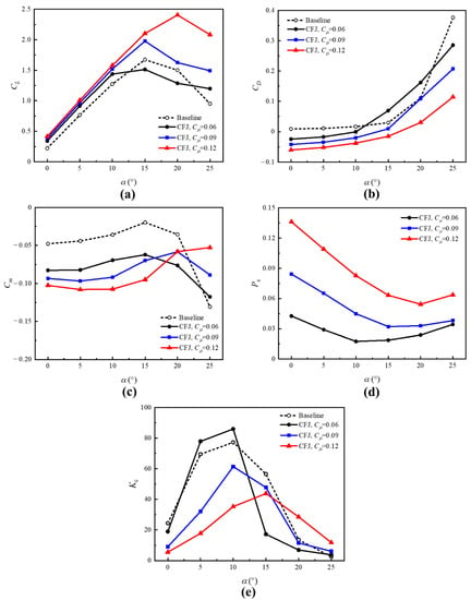
Figure 4.
Aerodynamic performance of CFJ2412 airfoil with various Cμ values. (a) Lift coefficient. (b) Drag coefficient. (c) Moment coefficient. (d) Power coefficient. (e) Corrected aerodynamic efficiency.
Figure 5 shows the Mach contours and streamlines of CFJ2412 airfoil with various Cμ values at α = 10°, where the CFJ could enhance the LE suction peak and the flow velocity on the airfoil suction surface compared with the baseline. The accelerated flow increases circulation and thus results in lift augmentation. As the Cμ increases, a larger high-speed region is found on the airfoil suction surface, which further increases the lift as denoted in Figure 4a. Figure 6 shows the Mach contours and streamlines at α = 20°. It is clearly observed that the large flow separation occurs at the TE of the baseline airfoil. When Cμ = 0.06, the flow separation phenomenon becomes even more pronounced. With the increase of Cμ, the flow separation is effectively suppressed and is almost eliminated at Cμ = 0.12. The reason is that a larger Cμ allows a stronger mixing of the jet flow and the main flow, which is conducive to overcoming the adverse pressure gradient and thus delaying the flow separation.
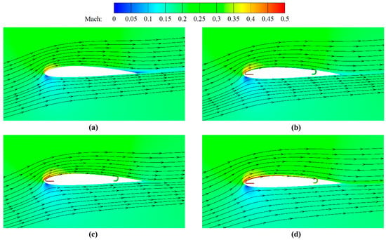
Figure 5.
Mach contours and streamlines of CFJ2412 airfoil with various Cμ values at α = 10°. (a) Baseline. (b) Cμ = 0.06. (c) Cμ = 0.09. (d) Cμ = 0.12.
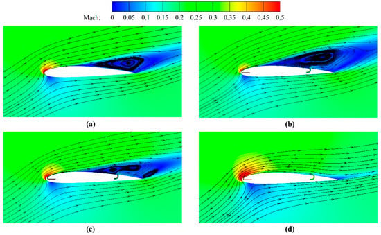
Figure 6.
Mach contours and streamlines of CFJ2412 airfoil with various Cμ values at α = 20°. (a) Baseline. (b) Cμ = 0.06. (c) Cμ = 0.09. (d) Cμ = 0.12.
4.2. Effect of Injection Slot Location
This section investigates the effect of the injection slot location on the aerodynamics of the CFJ2412 airfoil at α = 0° and 10°. As denoted in Figure 7, four injection slot locations are selected, including xj = 2%c, 5%c, 8%c and 10%c. As aforementioned, the suction slot location is 75%c. The injection and suction slot sizes are 0.65%c and 1.3%c, respectively. The injection and suction slot angles are 33.4° and 70°.

Figure 7.
Schematic diagram of CFJ airfoils with various injection slot locations.
Figure 8 demonstrates the aerodynamic performance of CFJ airfoils with different injection slot locations. The lift forces generated by the CFJ airfoils with different xj values at α = 0° and 10° are larger than the baseline. However, the variation of the injection slot location is barely influential to the lift coefficient. It could also be derived from the Mach contours and streamlines in Figure 9 that the flow fields of CFJ airfoils with different injection slot locations at α = 10° are almost identical. For the drag production, the drag coefficient overall shows an increasing trend as the injection slot moves downstream at α = 0° while decreasing monotonically at α = 10°. The nose-down moment becomes larger with the increase of xj at α = 10°. In view of the power consumption, the power coefficient decreases first and then increases at α = 0°, while increasing monotonically at α = 10°. Figure 10 depicts the pressure coefficient distributions of CFJ2412 airfoils with various injection slot locations at α = 10°, where the injection slot location of xj = 2%c is closest to the suction peak of the LE, which could lead to a reduction in the energy expenditure. That is why the power coefficient increases monotonically at α = 10°. Additionally, the corrected aerodynamic efficiency decreases monotonically at α = 10° as the injection slot location moves downstream, which is mainly due to the larger power consumption. At α = 0°, the injection slot location has less influence on the corrected aerodynamic efficiency.
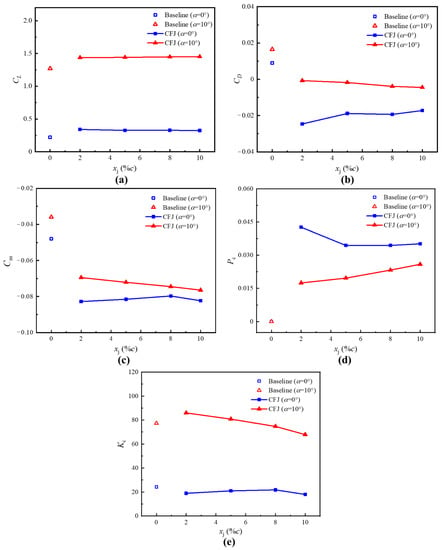
Figure 8.
Effect of injection slot location on CFJ airfoil aerodynamics (Cμ = 0.06). (a) Lift coefficient. (b) Drag coefficient. (c) Moment coefficient. (d) Power coefficient. (e) Corrected aerodynamic efficiency.
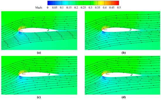
Figure 9.
Mach contours and streamlines of CFJ2412 airfoil with various injection slot locations at α = 10°. (a) xj = 2%c. (b) xj = 5%c. (c) xj = 8%c. (d) xj = 10%c.
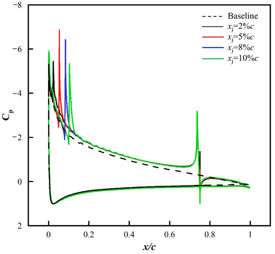
Figure 10.
Pressure coefficient distributions of CFJ2412 airfoils with various injection slot locations at α = 10°.
4.3. Effect of Injection Slot size
The effect of the injection slot size Aj is assessed in the present section, where five values are chosen, including Aj = 0.5%c, 0.65%c, 0.8%c, 1%c and 1.2%c. Figure 11 demonstrates the diagram of CFJ airfoils with various injection slot sizes, in which the injection and suction slot locations are 2%c and 75%c. The suction slot size is 1.3%c. The injection and suction slot angles are 33.4° and 70°.

Figure 11.
Schematic diagram of CFJ airfoils with various injection slot sizes.
Figure 12 compares the aerodynamic performance of CFJ airfoils with different injection slot sizes at α = 0° and 10°. It is evident that the lift coefficient changes slightly with the increase in the injection slot size. The drag coefficient first increases and then decreases. The larger the angle of attack, the smaller the injection slot size corresponding to the maximum drag production. By the CFJ, the pitching moment coefficient is significantly reduced. The power consumption first decreases and then increases. At α = 10°, the power coefficient corresponding to the injection slot size of 0.8%c is the smallest. In view of the corrected aerodynamic efficiency, the maximum Kc at α = 10° is achieved in the case of Aj = 0.65%c, which is 11.3% higher than the baseline airfoil. At α = 0°, the maximum Kc at α = 0° could be obtained when Aj = 1%c, which could achieve an enhancement of 125.6% compared with the baseline.
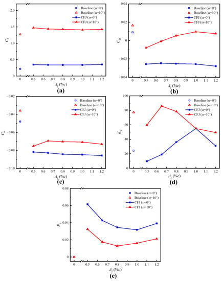
Figure 12.
Effect of injection slot size on CFJ airfoil aerodynamics (Cμ = 0.06). (a) Lift coefficient. (b) Drag coefficient. (c) Moment coefficient. (d) Power coefficient. (e) Corrected aerodynamic efficiency.
Figure 13 demonstrates the Mach contours and streamlines of CFJ2412 airfoil with various injection slot sizes at α = 10°. It could be seen that the flow fields are similar to each other, therefore the corresponding lift forces are close, as shown in Figure 12a. Additionally, with the increase of the injection slot size, the airflow velocity around the injection gradually decreases. Hence, according to Equation (1), when Cμ is fixed, the required mass flow rate is larger. Furthermore, since the mass flow rates at the injection and suction are equal, the airflow is accelerated near the suction slot, as shown in Figure 13. It is also known that the case of Aj = 0.5%c and the case of Aj = 1.2%c suffer from the flow separation around the suction cavity and the injection cavity, which leads to a larger energy expenditure than the case of Aj = 0.8%c as denoted in Figure 12d.
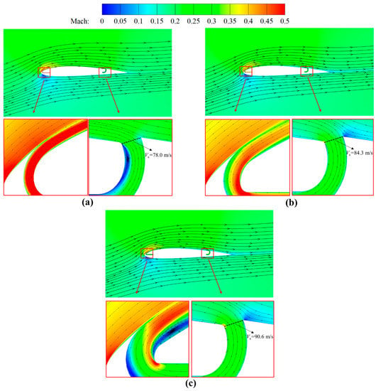
Figure 13.
Mach contours and streamlines of CFJ2412 airfoil with various injection slot sizes at α = 10°. (a) Aj = 0.5%c. (b) Aj = 0.8%c. (c) Aj = 1.2%c.
4.4. Effect of Suction Slot Location
The present section is to investigate the effect of the suction slot location xs on the CFJ2412 airfoil. Four values are chosen, including xs = 65%c, 70%c, 75%c and 80%c. The diagram of CFJ airfoils with various suction slot locations is shown in Figure 14. The injection and suction slot sizes are 0.65%c and 1.3%c. The injection slot location is 2%c. The injection and suction slot angles are fixed at 33.4° and 70°, respectively.

Figure 14.
Schematic diagram of CFJ airfoils with various suction slot locations.
Figure 15 demonstrates the effect of the suction slot location on the CFJ airfoil performance at α = 0° and 10°, in which the variation of the suction slot location has little influence on the lift coefficient. It could also be evidenced by Figure 16, where flow features are identical for different suction slot locations. The drag coefficient increases monotonously as the suction slot location move downstream while the pitching moment coefficient decreases monotonously. As for the power consumption, the increase in the suction slot location reduces the power coefficient, but the overall impact is minimal. Consequently, the corrected aerodynamic efficiency decreases monotonously with the increased suction slot location. When xs = 65%c and α = 10°, the corrected aerodynamic efficiency could achieve an enhancement of 41.1% compared with the baseline airfoil.
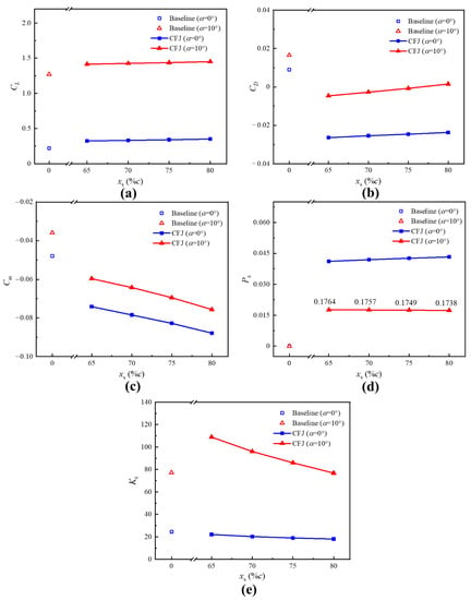
Figure 15.
Effect of suction slot location on CFJ airfoil aerodynamics (Cμ = 0.06). (a) Lift coefficient. (b) Drag coefficient. (c) Moment coefficient. (d) Power coefficient. (e) Corrected aerodynamic efficiency.
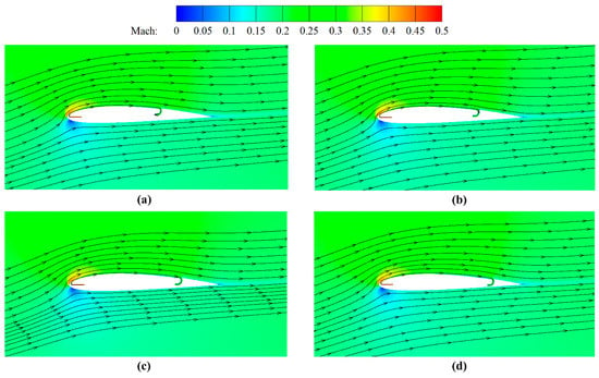
Figure 16.
Mach contours and streamlines of CFJ2412 airfoil with various suction slot locations at α = 10°. (a) xs = 65%c. (b) xs = 70%c. (c) xs = 75%c. (d) xs = 80%c.
Figure 17 shows the corresponding pressure coefficient distributions with various suction slot locations at α = 10°, where the area enclosed by the Cp curve achieves an obvious promotion with the CFJ effect, which verifies the lift enhancement. Moreover, the suction peak at the TE slightly decreases as the suction slot location moves downstream, which indicates that the pressure around the suction is higher. Therefore, the power coefficient is slightly reduced with the increase of the suction slot location.
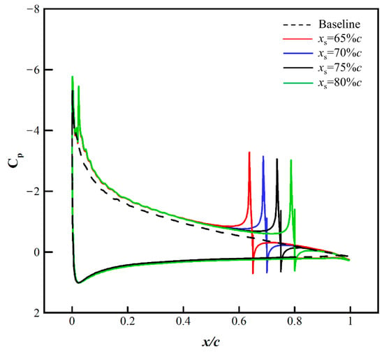
Figure 17.
Pressure coefficient distributions of CFJ2412 airfoils with various suction slot locations at α = 10°.
4.5. Effect of Suction Slot Size
This section investigated the aerodynamic performance of the CFJ2412 airfoil with various suction slot sizes. As demonstrated in Figure 18, the suction slot size is chosen as 1.1%c, 1.3%c, 1.5%c, 1.7%c, and 1.9%c, respectively. The injection slot size is 0.65%c. The injection slot locations are 2%c and 75%c, respectively, with the injection and suction slot angles 33.4° and 70°.

Figure 18.
Schematic diagram of CFJ airfoils with various suction slot sizes.
Figure 19 plots the aerodynamic characteristics comparison of the baseline and CFJ airfoils with different suction slot sizes. In Figure 19a, with the increase of the suction slot size, the lift coefficient almost remains the same. The drag coefficient shows a moderate increase with the enlargement of the suction size. The variation of the pitching moment coefficient demonstrates the opposite trend at α = 0° and 10°. According to Figure 19d, the power coefficient at α = 10° slightly decreases with the increase of the suction slot size. As for the corrected aerodynamic efficiency, the Kc monotonously decreases as the suction slot size increases. The case when As = 1.1%c and α = 10° could achieve the highest Kc with an increment of 25.8% in comparison to the baseline, which demonstrates that a relatively smaller suction slot size is more beneficial to the airfoil aerodynamic characteristics.
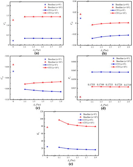
Figure 19.
Effect of suction slot size on CFJ airfoil aerodynamics (Cμ = 0.06). (a) Lift coefficient. (b) Drag coefficient. (c) Moment coefficient. (d) Power coefficient. (e) Corrected aerodynamic efficiency.
Figure 20 shows the pressure coefficient distributions of CFJ2412 airfoils with various suction slot sizes at α = 10°. It is observed that the variation of the suction slot size is barely influential to the pressure coefficient distribution near the injection slot. Therefore, the flow velocity near the injection slot is almost the same, and so is the CFJ required mass flow rate according to Equation (1). Since the required mass flow rate is almost unchanged, the increase in suction slot size could reduce the flow velocity at the suction. Furthermore, the suction peak at the TE is observed to become smaller with the enlargement of the suction slot size. As aforementioned, the high-pressure region around the suction slot makes the airflow suction easier. Consequently, the power coefficient decreases with the increase of the suction slot size as denoted in Figure 19d.
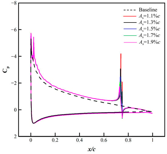
Figure 20.
Pressure coefficient distributions of CFJ2412 airfoils with various suction slot sizes at α = 10°.
4.6. Effect of Suction Slot Angle
The effect of the suction slot angle on the aerodynamics of the CFJ2412 airfoil is evaluated in the present section, where the θs are selected as 25°, 40°, 55°, and 70°, respectively. In the meantime, the injection and suction slot sizes are 0.65%c and 1.3%c, with the slot locations 2%c and 75%c, respectively. The injection slot angle is 33.4°. Figure 21 denotes the diagram of CFJ2412 airfoils with various suction slot angles.

Figure 21.
Schematic diagram of CFJ airfoils with various suction slot angles.
Figure 22 depicts the effect of the suction slot angle on the airfoil performance, where the variation of the θs is barely influential to the lift generation. It is evident that the increase in the suction slot angle could lead to a reduction in the drag coefficient. The reason is that the suction slot angle increment is able to augment the jet reaction force towards the LE direction to reduce the drag, which could be shown in Equation (2). Furthermore, the augmentation of the suction slot angle could lead to a slight increase in the power coefficient. It could be observed from Figure 23 that the increase in the suction slot angle makes the cross-section of the suction slot more parallel to the freestream. Therefore, the airflow needs to be more deflected to enter the suction pipe, which intuitively requires more energy. Also, this phenomenon could be verified by Figure 24, where a larger θs results in a higher suction peak at the TE. With identical suction peaks at the LE, the higher the suction peak at the TE, the greater the energy consumed. According to Figure 22e, it is observed that a larger θs is more effective to enhance the CFJ airfoil aerodynamics.
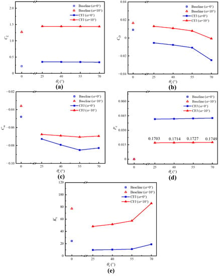
Figure 22.
Effect of suction slot angle on CFJ airfoil aerodynamics (Cμ = 0.06). (a) Lift coefficient. (b) Drag coefficient. (c) Moment coefficient. (d) Power coefficient. (e) Corrected aerodynamic efficiency.
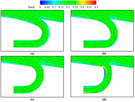
Figure 23.
Mach contours and streamlines of CFJ2412 airfoils with various suction slot angles near the suction slot at α = 10°. (a) θs = 25°. (b) θs = 40°. (c) θs = 55°. (d) θs = 75°.
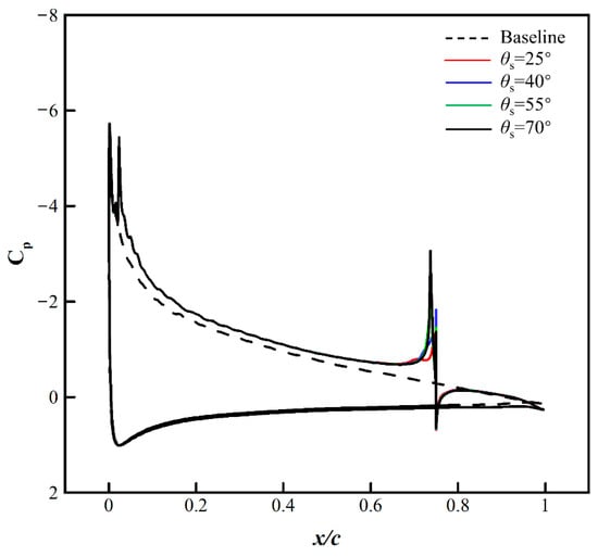
Figure 24.
Pressure coefficient distributions of CFJ2412 airfoils with various suction slot angles at α = 10°.
5. Conclusions
In the present work, the aerodynamic performance of the NACA2412 airfoil based on the CFJ technique is numerically investigated. It is verified that the numerical method based on the RANS equations and S-A turbulence model is suitable for the CFJ aerodynamic calculations. In addition, the effects of several crucial parameters on the CFJ airfoil aerodynamics are separately examined. The concluding remarks could be drawn as follows:
(1) A larger Cμ could substantially augment the lift due to the higher acceleration on the suction surface, resulting in the increment of the airfoil circulation. The drag is also significantly reduced on account of the super-suction effect at the LE of the airfoil. In addition, the increment of Cμ is conducive to overcoming the adverse pressure gradient and thus delaying the flow separation. However, a smaller Cμ is more beneficial to increasing the corrected aerodynamic efficiency at small angles of attack, with an enhancement of 11.3% compared with the baseline at Cμ = 0.06 and α = 10°.
(2) The variation of the injection slot location is barely influential to the lift coefficient. The injection slot location of xj = 2%c is closest to the suction peak of the LE, which could lead to a reduction in the energy expenditure at α = 10°. With the increase of the injection slot size, the power coefficient first decreases and then increases, and the corrected aerodynamic efficiency first increases and then decreases. The optimal corrected aerodynamic efficiency of α = 0° and α = 10° could be achieved when Aj = 1%c and Aj = 0.65%c, with an enhancement of 125.6% and 11.3% respectively compared with the baseline.
(3) The drag coefficient increases monotonously as the suction slot location moves downstream. The increase in the suction slot location reduces the power coefficient, but the overall impact is minimal. A relatively smaller suction slot size is more conducive to reducing the drag and augmenting the corrected aerodynamic efficiency. The case when As = 1.1%c and α = 10° could achieve the highest corrected aerodynamic efficiency, with an increment of 25.8% in comparison to the baseline. The increase of the suction slot angle is barely influential to the lift generation, but it could lead to a decrease in drag production. A larger suction slot angle is more beneficial to the CFJ airfoil aerodynamic performance enhancement.
Author Contributions
Conceptualization, R.W. and X.M.; methodology, R.W., X.M. and G.Z.; validation, formal analysis and investigation: R.W., X.M., G.Z. and P.Y.; writing—original draft preparation, R.W.; writing—review and editing, X.M. and P.Y.; supervision, G.Z., and P.Y.; project administration, X.M. and P.Y. All authors have read and agreed to the published version of the manuscript.
Funding
This research was funded by the National Natural Science Foundation of China under Grants 12102431, 11902320, and 12002340.
Institutional Review Board Statement
Not applicable.
Informed Consent Statement
Not applicable.
Data Availability Statement
Not applicable.
Conflicts of Interest
The authors declare no conflict of interest.
Abbreviations
| Aj | Injection slot size |
| As | Suction slot size |
| c | Chord length |
| CC | Circulation control |
| CFD | Computational Fluid Dynamics |
| CFJ | Co-flow jet |
| CL | Lift coefficient |
| CD | Drag coefficient |
| Cm | Pitching moment coefficient |
| cp | Constant pressure specific heat |
| Cp | Pressure coefficient |
| Cμ | Jet momentum coefficient |
| D | Drag |
| DES | Detached-Eddy Simulation |
| E | Total energy per unit mass |
| Fxcfj | Jet reaction force in the drag direction |
| Fycfj | Jet reaction force in the lift direction |
| FI | Inviscid fluxes |
| FV | Viscous fluxes |
| FVM | Finite volume method |
| Kc | Corrected aerodynamic efficiency |
| L | Lift |
| L/D | Lift-to-drag ratio |
| LE | Leading-edge |
| LES | Large-Eddy Simulation |
| Lxinj | Moment arm in x direction for the injection slot |
| Lxsuc | Moment arm in x direction for the suction slot |
| Lyinj | Moment arm in y direction for the injection slot |
| Lysuc | Moment arm in y direction for the suction slot |
| Injection mass flow rate | |
| Suction mass flow rate | |
| M | Pitching moment |
| Ma | Mach number |
| MCFJ | CFJ pitching moment |
| nx,ny | Normal vector components of the control surface |
| P | Power consumption |
| Pc | Power coefficient |
| pj | Static pressure at the injection cavity |
| ps | Static pressure at the suction cavity |
| ptj | Mass-averaged total pressure in the injection cavity |
| pts | Mass-averaged total pressure in the suction cavity |
| Q | Conserved variables |
| RANS | Reynolds averaged Navier-Stokes |
| Re | Reynolds number |
| Rx | Surface integral of pressure |
| Ry | Surface integral of shear stress |
| S | Control volume boundary |
| Sref | Reference area |
| S-A | Spalart-Allmaras |
| TE | Trailing-edge |
| Tts | Total pressure in the suction cavity |
| V∞ | Freestream velocity |
| Vj | Mass-averaged injection velocity |
| xj | Injection slot location |
| xs | Suction slot location |
| ZNMF | Zero-net mass flux |
| α | Angle of attack |
| γ | Specific heat ratio |
| η | Efficiency of the pumping system |
| θj | Injection slot angle |
| θs | Suction slot angle |
| ρ∞ | Freestream density |
| Ω | Control volume |
References
- Ashill, P.R.; Fulker, J.L.; Hackett, K.C. A review of recent developments in flow control. Aeronaut. J. 2005, 109, 205–232. [Google Scholar] [CrossRef]
- Bewley, T.R. Flow control: New challenges for a new renaissance. Prog. Aerosp. Sci. 2001, 37, 21–58. [Google Scholar] [CrossRef]
- Hirai, R.; Kawai, S. Analysis and robust method for source-term modeling of vortex generator. J. Aircr. 2021, 58, 958–970. [Google Scholar] [CrossRef]
- Eguea, J.P.; Bravo-Mosquera, P.D.; Catalano, F.M. Camber morphing winglet influence on aircraft drag breakdown and tip vortex structure. Aerosp. Sci. Technol. 2021, 119, 107148. [Google Scholar] [CrossRef]
- Zaki, A.; Abdelrahman, M.A.; Ayad, S.S.; Abdellatif, O.E. Effects of leading edge slat on the aerodynamic performance of low Reynolds number horizontal axis wind turbine. Energy 2022, 239, 122338. [Google Scholar] [CrossRef]
- Chaput, A.J. Multi-section wing capability for the vehicle sketch pad structural analysis module. In Proceedings of the 53rd AIAA Aerospace Sciences Meeting, Kissimmee, FL, USA, 5–9 January 2015. [Google Scholar]
- Zhang, Y.; Yang, P.; Li, R.; Chen, H. Unsteady simulation of transonic buffet of a supercritical airfoil with shock control bump. Aerospace 2021, 8, 203. [Google Scholar] [CrossRef]
- Werner-Spatz, C.; Heinze, W.; Horst, P.; Radespiel, R. Multidisciplinary conceptual design for aircraft with circulation control high-lift systems. CEAS Aeronaut. J. 2012, 3, 145–164. [Google Scholar] [CrossRef]
- Min, B.Y.; Lee, W.; Englar, R.; Sankar, L.N. Numerical investigation of circulation control airfoils. J. Aircr. 2009, 46, 1403–1410. [Google Scholar] [CrossRef]
- Xu, H.Y.; Qiao, C.L.; Yang, H.Q.; Ye, Z.Y. Active circulation control on the blunt trailing edge wind turbine airfoil. AIAA J. 2018, 56, 554–570. [Google Scholar] [CrossRef]
- Rizzetta, D.P.; Visbal, M.R.; Stanek, M.J. Numerical investigation of synthetic-jet flowfields. AIAA J. 1999, 37, 919–927. [Google Scholar] [CrossRef]
- Li, S.; Luo, Z.; Deng, X.; Liu, Z.; Gao, T.; Zhao, Z. Lift enhancement based on virtual aerodynamic shape using a dual synthetic jet actuator. Chin. J. Aeronaut. 2022; in press. [Google Scholar] [CrossRef]
- Reedy, T.M.; Kale, N.V.; Dutton, J.C.; Elliott, G.S. Experimental characterization of a pulsed plasma jet. AIAA J. 2013, 51, 2027–2031. [Google Scholar] [CrossRef]
- Zhang, W.; Shi, Z.; Li, Z.; Geng, X.; Zhang, C.; Sun, Q. Study on propagation mechanisms of the actuations generated by plasma synthetic jet actuator in a supersonic flow. Aerosp. Sci. Technol. 2022, 126, 107644. [Google Scholar] [CrossRef]
- Lefebvre, A.; Dano, B.; Bartow, W.B.; Fronzo, M.D.; Zha, G.C. Performance and energy expenditure of co-flow jet airfoil with variation of Mach number. J. Aircr. 2016, 53, 1757–1767. [Google Scholar] [CrossRef]
- Liu, J.; Chen, R.; You, Y.; Shi, Z. Numerical investigation of dynamic stall suppression of rotor airfoil via improved co-flow jet. Chin. J. Aeronaut. 2022, 35, 169–184. [Google Scholar] [CrossRef]
- Zha, G.C.; Paxton, C.D. A novel airfoil circulation augment flow control method using co-flow jet. In Proceedings of the 2nd AIAA Flow Control Conference, Portland, OR, USA, 28 June–1 July 2004. [Google Scholar]
- Zha, G.C.; Paxton, C.D.; Conley, C.A.; Wells, A.; Carroll, B.F. Effect of injection slot size on the performance of co-flow jet airfoil. J. Aircr. 2006, 43, 987–995. [Google Scholar] [CrossRef]
- Dano, B.; Kirk, D.; Zha, G.C. Experimental investigation of jet mixing mechanism of co-flow jet airfoil. In Proceedings of the 5th AIAA Flow Control Conference, Chicago, IL, USA, 28 June–1 July 2010. [Google Scholar]
- Dano, B.; Zha, G.C.; Castillo, M. Experimental study of co-flow jet airfoil performance enhancement using discreet jets. In Proceedings of the 49th AIAA Aerospace Sciences Meeting Including the New Horizons Forum and Aerospace Exposition, Orlando, FL, USA, 4–7 January 2011. [Google Scholar]
- Dano, B.; Lefebvre, A.M.; Zha, G.C. Mixing mechanism of a discrete co-flow jet airfoil. In Proceedings of the 41st AIAA Fluid Dynamics Conference and Exhibit, Honolulu, HI, USA, 27–30 June 2011. [Google Scholar]
- Zhang, S.L.; Yang, X.D.; Song, B.F.; Li, Z.Y.; Wang, B. Experimental investigation of lift enhancement and drag reduction of discrete co-flow jet rotor airfoil. Appl. Sci. 2021, 11, 9561. [Google Scholar] [CrossRef]
- Lefebvre, A.M.; Zha, G.C. Co-flow jet airfoil trade study part I: Energy consumption and aerodynamic efficiency. In Proceedings of the 32nd AIAA Applied Aerodynamics Conference, Atlanta, GA, USA, 16–20 June 2014. [Google Scholar]
- Wang, Y.; Zha, G.C. Study of Reynolds number effect for 2d co-flow jet airfoil at cruise condition. In Proceedings of the AIAA Aviation 2020 Forum, Virtual Event, 15–19 July 2020. [Google Scholar]
- Liu, Z.X.; Zha, G.C. Transonic airfoil performance enhancement using co-flow jet active flow control. In Proceedings of the 8th AIAA Flow Control Conference, Washington, DC, USA, 13–17 June 2016. [Google Scholar]
- Lei, Z.J.; Zha, G.C. Lift enhancement of supersonic thin airfoil at low speed by co-flow jet active flow control. In Proceedings of the AIAA Aviation 2021 Forum, Virtual Event, 2–6 August 2021. [Google Scholar]
- Wang, B.; Zha, G.C. Detached-eddy simulation of a co-flow jet airfoil at high angle of attack. J. Aircr. 2011, 48, 1495–1502. [Google Scholar] [CrossRef]
- Im, H.S.; Zha, G.C.; Dano, B. Large eddy simulation of co-flow jet airfoil at high angle of attack. J. Fluids Eng. 2014, 136, 021101. [Google Scholar] [CrossRef]
- Liu, J.; Chen, R.; Qiu, R.; You, Y.; Zhang, W. Study on dynamic stall control of rotor airfoil based on co-flow jet. Int. J. Aerosp. Eng. 2020, 2020, 8845924. [Google Scholar] [CrossRef]
- Xu, H.Y.; Qiao, C.L.; Ye, Z.Y. Dynamic stall control on the wind turbine airfoil via a co-flow jet. Energies 2016, 9, 429. [Google Scholar] [CrossRef]
- Zhang, J.H.; Xu, K.W.; Yang, Y.C.; Yan, R.; Patel, P.; Zha, G.C. Aircraft control surfaces using co-flow jet active flow control airfoil. In Proceedings of the 2018 Applied Aerodynamics Conference, Atlanta, GA, USA, 25–29 June 2018. [Google Scholar]
- Wang, R.C.; Ma, X.P.; Zhang, G.X.; Ying, P.; Wang, X.Y. Numerical investigation of co-flow jet airfoil with parabolic flap. Chin. J. Aeronaut. 2022; in press. [Google Scholar] [CrossRef]
- Xu, K.W.; Zha, G.C. Mitigation of serpentine duct flow distortion using co-flow jet active flow control. In Proceedings of the AI-AA Aviation 2020 Forum, Virtual Event, 15–19 June 2020. [Google Scholar]
- Xu, K.W.; Zha, G.C. System energy benefit using co-flow jet active separation control for a serpentine duct. Aerosp. Sci. Technol. 2022, 128, 107746. [Google Scholar] [CrossRef]
- Perlin, D.; Zha, G.C. Numerical study of reverse thrust generation using co-flow jet. In Proceedings of the AIAA Scitech 2022 Forum, San Diego, CA, USA, 3–7 January 2022. [Google Scholar]
- Xu, K.W.; Ren, Y.; Zha, G.C. Numerical analysis of energy expenditure for coflow wall jet separation control. AIAA J. 2022, 60, 3267–3285. [Google Scholar] [CrossRef]
- Aftab, S.M.A.; Mohd, R.A.S.; Razak, N.A.; Ahmad, K.A. Turbulence model selection for low Reynolds number flows. PLoS ONE 2016, 11, e0153755. [Google Scholar] [CrossRef]
- Allmaras, S.R.; Johnson, F.T. Modifications and clarifications for the implementation of the Spalart-Allmaras turbulence mode. In Proceedings of the 7th International Conference on Computational Fluid Dynamics (ICCFD7), Big Island, HI, USA, 9–13 July 2012. [Google Scholar]
- Spalart, P.; Allmaras, S. A one-equation turbulence model for aerodynamic flows. In Proceedings of the 30th Aerospace Sci-ences Meeting and Exhibit, Reno, NV, USA, 6–9 January 1992. [Google Scholar]
- Xu, K.W.; Zha, G.C. High control authority three-dimensional aircraft control surfaces using coflow jet. J. Aircr. 2021, 58, 72–84. [Google Scholar] [CrossRef]
Publisher’s Note: MDPI stays neutral with regard to jurisdictional claims in published maps and institutional affiliations. |
© 2022 by the authors. Licensee MDPI, Basel, Switzerland. This article is an open access article distributed under the terms and conditions of the Creative Commons Attribution (CC BY) license (https://creativecommons.org/licenses/by/4.0/).