Article

Dynamic Aircraft Wake Separation Based on Velocity Change

College of Air Traffic Management, Civil Aviation Flight University of China, Guanghan 618307, China
*
Authors to whom correspondence should be addressed.
Aerospace 2022, 9(11), 633; https://doi.org/10.3390/aerospace9110633
Submission received: 23 August 2022 / Revised: 12 October 2022 / Accepted: 17 October 2022 / Published: 22 October 2022
(This article belongs to the Special Issue Flight Simulation and Aircraft Autonomy)

Abstract

:
Traditional research on static wake-vortex reduction usually considers only the influence of external environmental factors, while ignoring the dynamic change in an aircraft’s flight state. In order to solve this problem, this paper proposes a method to reduce separation using dynamic wake information based on changes in flight velocity. Firstly, relying on the wake-vortex generation and dissipation model, the initial circulations and dissipation parameters of the wake vortex at different aircraft velocities are calculated. Then, the complete evolution process of the wake vortex generated by different types of aircraft at different velocities is analyzed, and the evolution law of a wake vortex with changing velocity is obtained. Afterwards, according to the actual aerodynamic shape of CRJ-900, the aerodynamic model for CRJ-900 when it encounters a wake vortex is established. The situation of an CRJ-900 encountering a wake vortex under TBS is analyzed, which proves that TBS is safe and has a certain reduction potential. Then, taking the rolling moment coefficient as the safety index, the minimum safe separations at different velocities are calculated. Finally, a simulation for the separation reduction based on a dynamic wake vortex is carried out. Compared with the static wake-based separation, the dynamic wake-based separation technology can greatly reduce the aircraft separation requirements while ensuring the operation safety. The final simulation results show that the dynamic separation reduction in CRJ-900 following a medium and heavy aircraft can reach 44.3% and 51.6%, respectively.

1. Introduction

During flight, an aircraft generates lift through the pressure difference between the upper and lower surfaces of an airfoil. At the same time, there is also airflow from the lower surface around the wing tip to the upper surface, thus creating two vortices near the wing tip which rotate in opposite directions, namely, the wake vortex. Since wake is an important factor affecting flight safety, a large number of scholars have conducted extensive and in-depth research on it, mainly performing studies on wake generation and dissipation, wake encounter, wake response of a following aircraft, and safety separation standards [1]. Crow et al. studied the generation and dissipation mechanisms of an approaching wake vortex through extensive observations and experiments [2]. Greene et al. developed the first wake-vortex dissipation model, called the Greene model [3]. Holzäpfel et al. proposed a two-stage wake dissipation (P2P) model by numerically simulating the wind, turbulence and ground effects in an integrated manner [4]. Speijker et al. were the first to use rolling angular velocity to assess the severity of wake encounters in a following aircraft [5]. Marques et al. developed a computational model of the rolling moment generated by an aircraft encountering a wake, and then used it for the safety assessment of wake encounters in the following aircraft [6]. Gerben et al. proposed using the rolling-moment coefficient to evaluate the severity of wake encounters in a following aircraft, and validated the grading criteria for the roll-moment coefficient [7]. Moreover, the European-developed wake-vortex prediction system WSVS can dynamically adjust the separation between aircrafts without compromising the safety [8,9,10]. NASA developed a wake prediction system (AVOSS), which combines real-time weather data, wake-detection data, and wake models to determine safe wake separations [11]. Subsequently, Wei Zhiqiang et al. analyzed the variation law of wake-vortex dissipation with a side wind, through a theoretical study on the aircraft wake-vortex dissipation mechanism [12,13]. Zhang Junduo et al. studied the evolution of wake in ARJ21 under the influence of side winds in the near-ground phase [14]. Wang Xuan et al. proposed a Doppler LIDAR to establish a radial wind-speed-based wake-vortex identification method [15]. Han Hongrong et al. established a model for calculating the disturbance parameters of an aircraft by considering the influence of various aircraft parameters on the roll process, and calculated a safe flight separation based on this model [16]. Pan Weijun et al. analyzed the safety of an ARJ21 aircraft based on ICAO wake separation standard and the reduction potential of wake separation, and then calculated the separation reduction when ARJ21 followed different aircraft [17].
Evidently, significant research has been performed on wake vortices; however, most of these works only focus on the influence of external environmental factors such as side wind and ground effect on the wake-vortex evolution and safe wake separation, while, in fact, wake-vortex evolution and separation safety are closely related to an aircraft’s own flight status, which is also key to achieving dynamic wake-separation reduction.
In this paper, based on the velocity change characteristics of a front and following aircraft during takeoff and approach phases, the generation and dissipation laws of wake vortices for different aircraft combinations at different velocities were researched. Combining this analysis with the aerodynamic model of CRJ-900 that encounters a wake vortex, the safe separations in longitudinal, vertical and lateral directions were calculated, for cases where CRJ-900 followed different aircraft at different velocities. Next, the dynamic wake-separation reduction simulation was performed based on these calculations.

1.1. Wake-Vortex Generation Model

According to a theory proposed by Kutta–Joukowski, aircraft lift is equal to the flux in vortex momentum, as expressed in the following equations
Γ 0 V b 0 ρ = ρ C l B 2 V 2 2 λ
b 0 = s B
where Γ0 is the initial wake vortex circulation, V is the flight velocity, b0 is the distance between both vortex centres, ρ is the air density, Cl is the lift coefficient, B is the wing span, and λ is the aspect ratio. Meanwhile, s is the load factor in the spreading direction, and s ≈ π/4 when the airfoil type is an elliptical wing.
Through Equations (1) and (2), the initial wake-vortex circulation can be expressed by the following equation
Γ 0 = C l V B 2 s λ
For asymmetric airfoils, the lift coefficient is calculated as follows:
C l = C l a ( a a 0 )
C l a = 2 π λ 2 + 4 + λ 2 β 2 η e ( 1 + tan 2 χ 1 / 2 β 2 )
tan χ 1 / 2 = tan χ 2 λ η 1 η + 1
where Cla is the slope of the lift line; a is the aircraft’s current angle of attack; a0 is the aircraft’s zero-lift angle of attack; ηe is the airfoil efficiency, generally taken as 0.95; χ1/2 is the swept-back angle of the 1/2 chord; and η is the root-to-tip ratio.
From the above formulas (1–6), it can be seen that the velocity of an aircraft in flight is the main factor affecting the initial circulation and the parameters of a wake vortex. In this paper, we choose A320, B738, A333 and B789 as the front aircraft, and Table 1, below, lists the specific parameters of each aircraft.

1.2. Wake-Vortex Dissipation Model

Wake-vortex dissipation is generally divided into two stages: the near-vortex dissipation stage and far-vortex dissipation stage. The near-vortex dissipation stage is slow, and generally dissipates about 10% of the initial circulation. Meanwhile, the far-vortex dissipation stage is a fast dissipation stage, in which the wake vortex dissipates rapidly. In addition, the near-vortex dissipation time is related to the turbulent-dissipation rate, initial characteristic velocity, and characteristic time.
{ b 0 = π 4 B r 0 = 0.052 B v 0 = Γ 0 2 π b 0 t 0 = b 0 v 0
where b0 is the distance between both vortex centers, r0 is the initial vortex core radius, v0 is the characteristic velocity, and t0 is the characteristic time.
Here, the turbulent-dissipation rate ε can be calculated by the following equation
{ ε = C m u 3 / 4 k 3 / 2 l R e = ρ V L μ I = 0.16 R e 1 / 8 l = 0.07 L / C m u 3 / 4 k = 3 ( I V ) 2 2
where Cmu is the turbulence parameter, taken as 0.09; k is the turbulent kinetic energy; l is the turbulence length scale; Re is the Reynolds number; and I is the turbulence intensity. In addition, L is the characteristic length, which is a ratio of wing area to wingspan.
The duration of the near-vortex dissipation stage, t*, can be calculated according to the equation proposed by Sarpkaya, given as follows [18]:
{ t * = ( 0.7475 / ε * ) 0.75 ( ε * 0.2535 ) ε * = ( t * / t 0 ) 0.25 e 0.7 t * t 0 ( 0.0121 ε * 0.2535 ) t * = t 0 ( 9.18 180 ε * ) ( 0.001 ε * 0.0121 ) t * = 9 t 0 ( ε * 0.001 )
ε * = ( ε b 0 ) 1 / 3 v 0
where ε is the turbulent dissipation rate, ε* is the vortex dissipation rate, and t* is the near vortex dissipation time.
Accordingly, the formula for far-vortex dissipation is as follows:
Γ t Γ 0 = e ( c t 0 t * ) v 0 t b 0
As can be seen from the above equation, the flight velocity of an aircraft is an important factor affecting wake-vortex dissipation.

1.3. Wake-Vortex Velocity Model

The Hallock–Burnham model is often used in wake-related studies due to its high consistency with the measured data of wake [19]. Similarly, the Hallock–Burnham model is chosen in this paper to calculate the induced wake velocities of different aircrafts.
The corresponding formula for the far-vortex dissipation is as follows:
v ( r ) = Γ 2 π r r 2 + r 0 2
where Г is the wake-vortex circulation, r is the distance to the vortex center, and r0 is the initial vortex core radius.
Figure 1, below, shows the induced wake velocities of different aircrafts at 174.95 kts.

1.4. Following-Aircraft Response Model

This paper chooses a CRJ-900 as the following aircraft to research the lift change and generated roll moment when the aircraft encounters a wake vortex, and calculates the roll moment coefficient as a safety index.
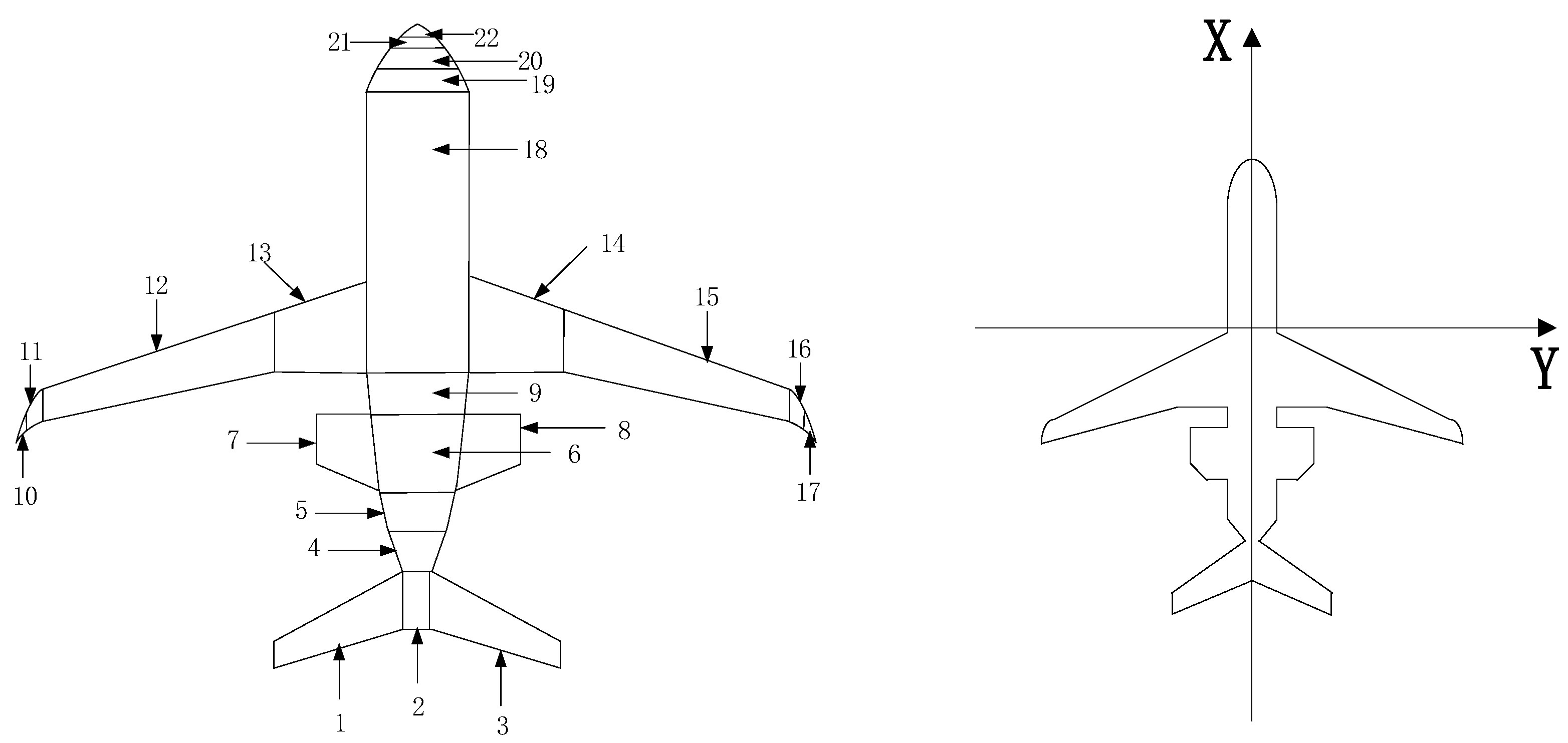
Since the configuration of CRJ-900 is different from the standard aircraft, this paper divides CRJ-900 into four parts: fuselage (4, 5, 6, 9, 18–22 in Figure 2), wing (10–17 in Figure 2), engine (7, 8 in Figure 2), and tail wing (1, 2, 3 in Figure 2), with 22 quadrilateral blocks, based on the actual aerodynamic shape of CRJ-900, for calculating the lift and roll moment when encountering a wake vortex. The force model of CRJ-900 and the coordinate axes are shown in Figure 2.
When the follow aircraft enters the wake-vortex area of front aircraft, its lift changes due to the additional airflow. The amount of lift change in the wing caused by the wake-vortex field, ΔLwing, can be expressed by the following equation:
Δ L w i n g = 1 2 ρ v f 2 B 2 B 2 Δ C l c ( y ) d y
where ρ is the current air density, vf is the flight velocity of follow aircraft, c(y) is the wing chord length at the current position, and ΔCl is the coefficient describing the amount of change in the lift.
The fuselage of am CRJ-900 aircraft can be regarded as a slender cylinder with a small angle of attack, and, according to the linearization theory of a slender spinning body, its lift variation ΔLbody can be expressed by the equation given as follows [20]:
Δ L b o d y = 1 2 ρ v f 2 s b ( 2 Δ a ) cos ( Δ a ) + 1 2 ρ v f 2 s b ( 2 Δ a ) sin ( Δ a )
where Sb is the projected area of the fuselage and Δa is the amount of change in the angle of attack.
The arrangement of the vortex surface of the engine and tail wing of the CRJ-900 aircraft can be regarded as a plate, and, according to the vortex plate numerical method, the lift variation in engine and tail wing ΔLep can be expressed as follows [21]:
Δ L e p = ρ v f j = 1 n V j S j
where Vj is the induced velocity of the wake vortex of the front aircraft transferred to the engine or tank of the following aircraft, and Sj is the engine or tail-wing infiltration area.
The formula for calculating the rolling moment Z generated at the wing profile is as follows:
Z = 1 2 ρ v f C l a B 2 B 2 v ( r ) c ( y ) y d y
Then, the rolling moment coefficient (RMC), utilized as the measure of wake encounter safety, can be expressed by the following equation [7]:
σ R M C = Z 1 2 ρ v f 2 S f B f
where σRMC is the rolling moment coefficient, Sf is the wing area of the follow aircraft, and Bf is the wing span of the follow aircraft.
In addition, the maximum rolling moment Zmax can be obtained according to the limit value of the rolling moment coefficient of the aircraft as:
Z max = 1 2 ρ v f 2 S f B f σ R M C max
where σRMCmax is the maximum rolling moment coefficient that a follow aircraft can withstand.
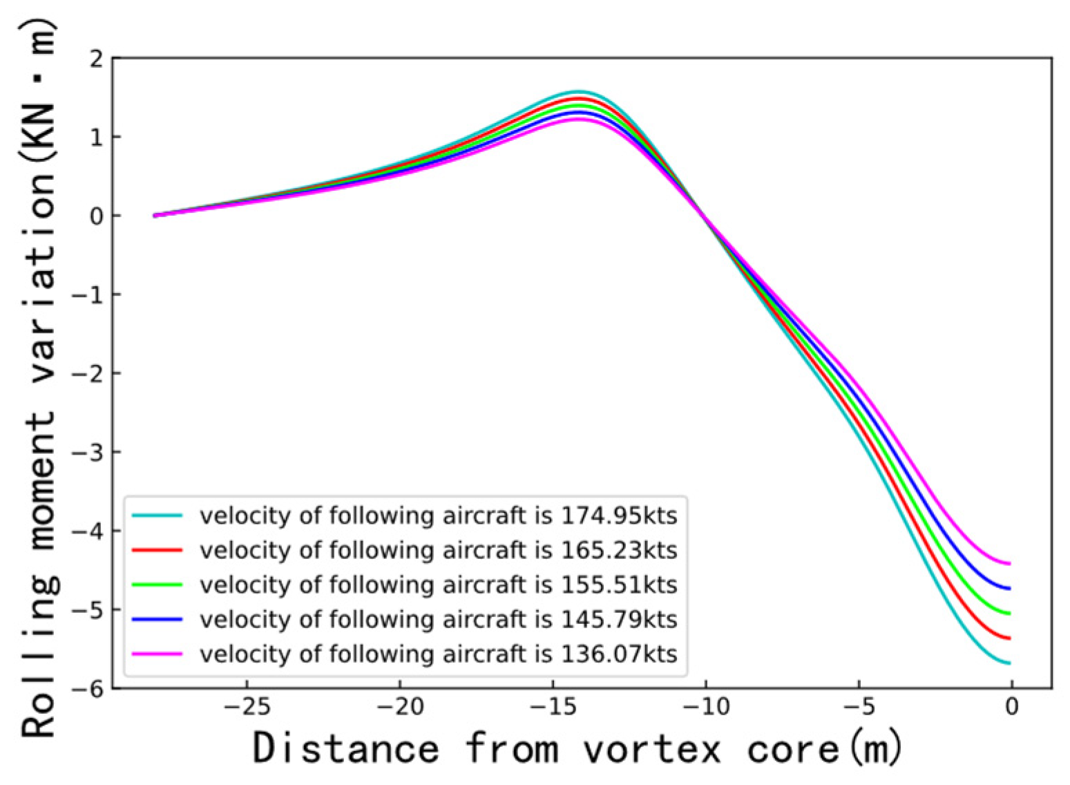
Figure 3, below, shows the rolling moment of an CRJ-900 encountering wake-vortex under time separation of 100 s at different velocities, when the front aircraft is an A320.

2. Result

2.1. Wake-Vortex Generation and Dissipation at Different Velocities

The flight velocity of the front aircraft is an important factor affecting the initial circulation of the wake vortex. The initial circulations produced by different front aircrafts at different velocities are shown in Table 2. Fundamentally, the initial circulation increases linearly with the increase in flight velocity. Moreover, the heavier the aircraft, the larger the wing span and the wing area, and the greater the rate of change in the initial circulation. The initial circulation of the A320 is least affected by the flight velocity, while that of the A333 is most affected.
Furthermore, the flight velocity also significantly affects the dissipation of a wake vortex. The turbulent-dissipation rate, vortex-dissipation rate, and duration of the near-vortex stage of different types of front aircraft at different velocities are shown in Table 3, Table 4 and Table 5, respectively. Evidently, the turbulent-dissipation rate tends to increase linearly as the flight velocity increases, where the lighter the aircraft, the greater the rate of change. Meanwhile, the vortex-dissipation rate decreases linearly with increasing flight velocity. In addition, the lighter the aircraft, the smaller the wingspan and wing area, and the greater the vortex dissipation rate. Accordingly, the vortex-dissipation rates of heavy aircrafts are greater than those of medium aircrafts. Lastly, the duration of a near-vortex stage decreases linearly with increasing flight velocity; the heavier the aircraft, the larger the wing span and wing area, and the greater the rate of change.
Considering the generation and dissipation characteristics of a wake vortex for the above aircraft, the evolution of wake vortices of these different aircrafts at different flight velocities was predicted, and the results are shown in Figure 4.
Evident from the figure, the wake-vortex evolution characteristics for all types of aircraft show a similar trend, where the higher the aircraft flight velocity, the larger the initial circulation and the longer the duration of the near-vortex stage. In the far-vortex stage, there exists a circulation value at which the dissipation times of wake vortices generated by the same aircraft at different flight velocities tend to be the same, which is called “dividing circulation” in this paper. In particular, the dividing circulation for the medium aircraft is about 75 m2/s, and the required dissipation time is about 25 s. Meanwhile, the dividing circulations of B789 and A333 are about 115 m2/s and 127 m2/s, respectively, and the required dissipation times are around 45 s. The change in flight velocity affects both the initial circulation and wake-vortex dissipation. Before reaching the dividing circulation, the larger the initial flight velocity, the larger the initial circulation, and the slower the dissipation of a wake vortex where more time is required to dissipate to a fixed circulation value. However, after reaching the dividing circulation, the larger the initial flight velocity, the larger the initial circulation, the faster the dissipation of a wake vortex, and the less the time is required to dissipate to a fixed circulation value.

2.2. Wake-Vortex Encounter at Different Velocities

The flight velocity of the following aircraft affects the impact when it encounters a wake vortex and the wake separation. In this work, by researching the ADS-B data of different aircrafts at Chengdu Shuangliu International Airport, we found that the flight velocity of all aircrafts in the terminal area is usually in the range of 70–90 m/s. In this paper, the rolling-moment coefficients of CRJ-900 under different flight velocities were calculated based on the dividing circulation, and the results are shown in Table 6.
The limit values of rolling-moment coefficients for medium aircrafts exemplified by the ICAO and RECAT-EU are 0.065 and 0.048, respectively [22], and the control authority of the roll-moment coefficient for aircrafts using ailerons is 0.05 to 0.07 [17]. It can be seen that the roll-moment coefficient that a CRJ-900 aircraft can withstand during its encounter with dividing circulation is much larger than the above-defined safety index; thus, the critical circulation that a CRJ-900 can withstand is much smaller than the dividing circulation.
London Heathrow Airport has been implementing time-based separation (TBS) in recent years, and research shows that TBS can lead to dynamic wake separation. According to the TBS issued by ICAO, the time separation when a CRJ-900 (F class) follows an A320 or B738 (C class) is 100 s, and the time separation when an A333 or B789 (B class) follows is 120 s. As shown in Figure 3, above, as the distance from the vortex center increases, the rolling moment of the CRJ-900 first decreases, then increases, and, finally, decreases again. In this research, the maximum rolling moment and the RMC of the following aircraft encountering a wake vortex under TBS is calculated, and the results are shown in Table 7, below.
As show in Table 7, the rolling moment of a CRJ-900 when following a B-class aircraft is greater than when following a C-class aircraft under TBS. The smaller the flight velocity of the front aircraft and the higher the flight velocity of the following aircraft, the greater the rolling moment and RMC. The impact of encountering a wake vortex when CRJ-900 maintains a certain flight separation from the front aircraft according to TBS is far less than the affordability of the CRJ-900 itself. TBS standard has some potential for reduction.
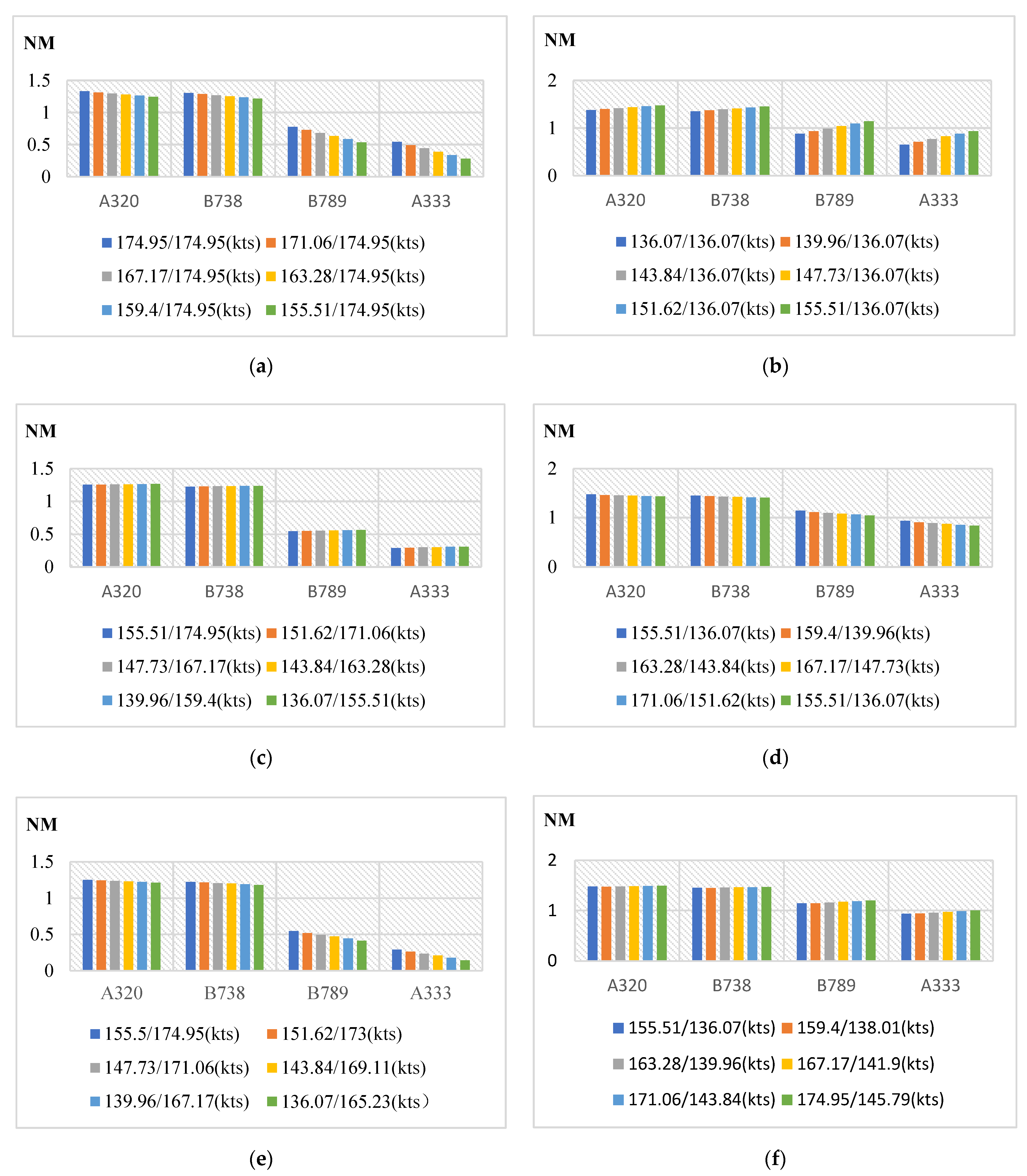
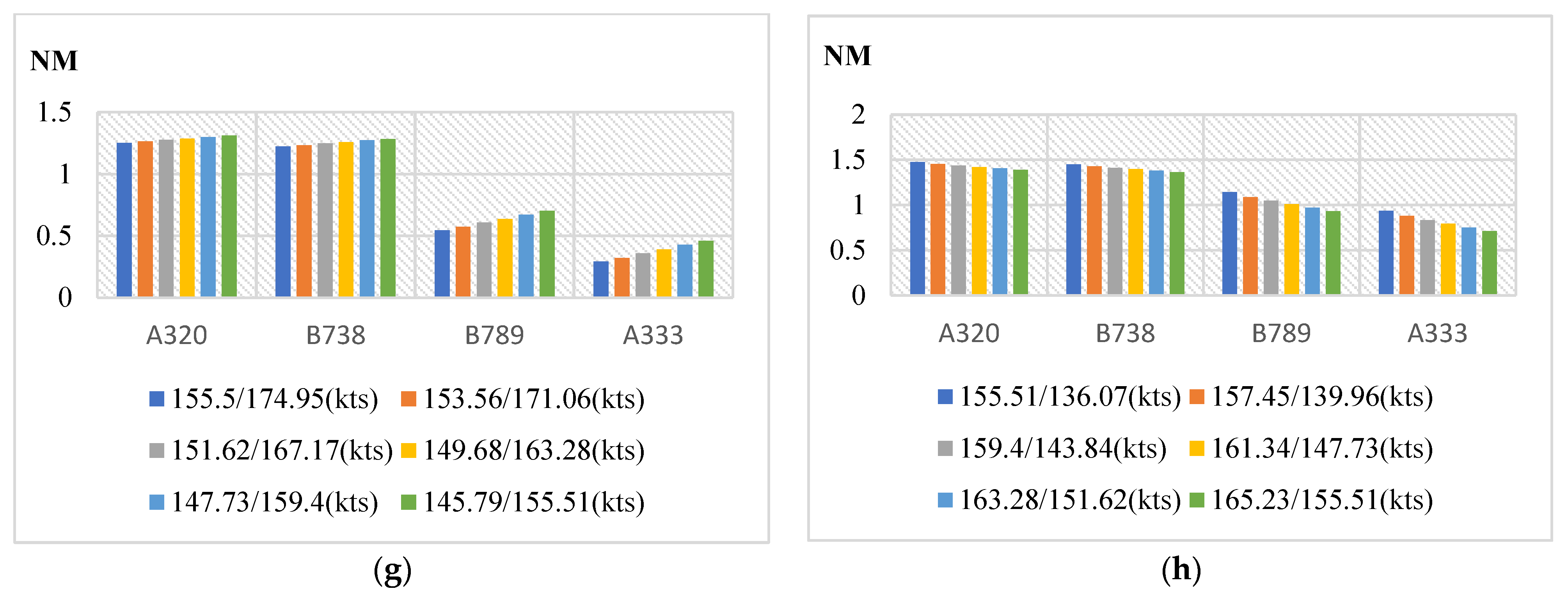
By using the minimum roll-moment coefficient of 0.048 as the critical value in the above safety index, the minimum required flight separation can be calculated. This paper analyzes several velocity variations in front and following aircrafts that may occur during takeoff and approach, and classifies them into eight categories: (1) during approach, the front aircraft decelerates while the following aircraft’s velocity remains unchanged; (2) during takeoff, the front aircraft accelerates while the following aircraft’s velocity remains unchanged; (3) during approach, the front and following aircraft decelerate with the same acceleration; (4) during takeoff, the front and following aircraft accelerate with the same acceleration; (5) during approach, the front and following aircraft decelerate, and the front one has a higher acceleration; (6) during takeoff, the front and following aircraft accelerate and the front one has a higher acceleration; (7) during approach, the front and following aircraft decelerate and the following one has a higher acceleration; (8) during takeoff, the front and following aircraft accelerate and the following one has a higher acceleration. Based on the above eight cases, the reduction in required separation between front and following aircrafts at different velocities relative to the ICAO standard were calculated, re-spectively, and the results are provided in Figure 5.
As shown in Figure 5, the heavier the front aircraft is, the smaller the reduction in the required separation, and the greater is the effect of velocity change on the minimum sepa-ration. During approach, when the front aircraft decelerates and the following aircraft’s velocity remains unchanged, the separation reduction is small. Similarly, the separation reduction also decreases when the front and following aircraft both decelerate, and the front one has a higher acceleration. In contrast, if the following one has a higher accelera-tion, the separation reduction increases. In this phase, the following aircraft can obtain the maximum separation reduction by decelerating with a large acceleration.
Compared to the approach phase, the separation reduction during takeoff is larger; where the reduction is greatest when the front aircraft’s acceleration is higher than that of the rear aircraft. In addition, when the front aircraft accelerates and the following aircraft’s velocity remains unchanged, the separation reduction increases.
When both front and following aircraft accelerate, if the front one has a higher accel-eration, the separation reduction increases, whereas if the following one has a higher ac-celeration, the separation reduction decreases. In this phase, the front aircraft can obtain the maximum separation reduction by decelerating with a large acceleration.

2.3. Dynamic Wake-Separation Reduction Simulation

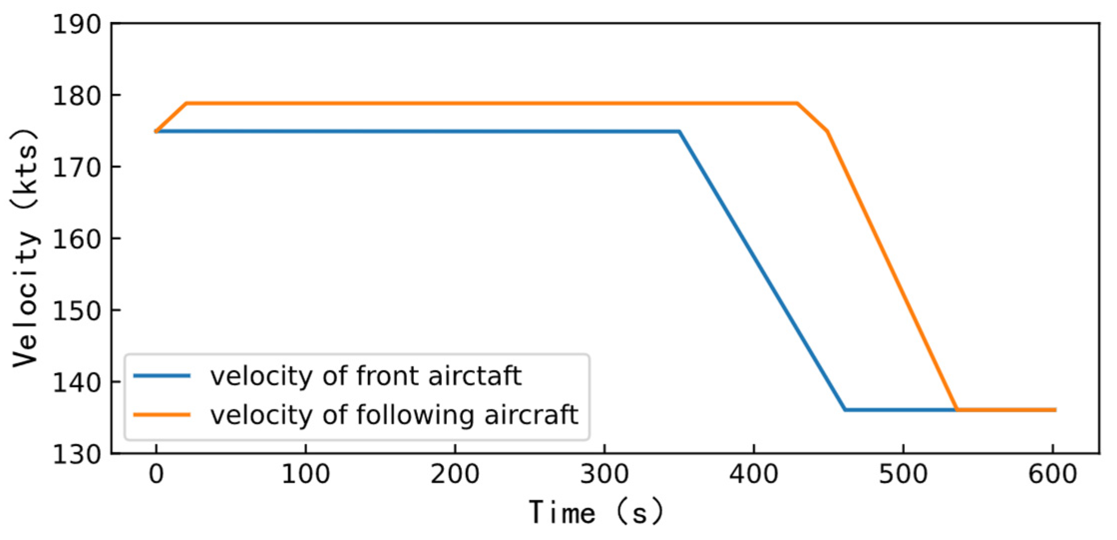
Essentially, the above-mentioned calculation results create the conditions for the realization of dynamic wake-separation reduction. Based on the variation in the flight velocity of various aircrafts in the ADS-B data of Chengdu Shuangliu International Airport, a set of velocity profiles of the CRJ-900 following medium and heavy aircrafts is constructed, before the front aircraft flies over the threshold (which is 600 s). Here, the following aircraft can adjust the separation by changing the flight velocity, as elaborated in Figure 6.
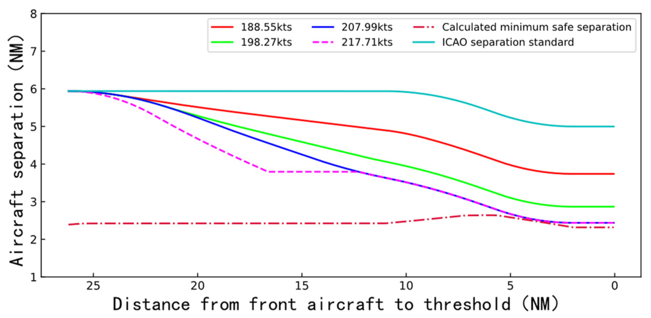
The circumstances of separation change when a CRJ-900 follows a medium and heavy aircraft throughout the threshold segment are shown in Figure 7 and Figure 8. The horizontal axis represents the distance from the front aircraft to the runway threshold, and the vertical axis represents the separation between the front and the following aircraft. The minimum separation at each position is expanded by 10% to further ensure safety, as shown by the dotted line in the figures. The legends show the flight velocities of the following aircraft after acceleration. For the whole segment, the final flight separation is the value corresponding to the vertical coordinate of each curve in the figure when the horizontal coordinate is 0. If the velocities of the front and following aircrafts remain constant, in order to maintain the minimum safety separation specified by ICAO, CRJ-900 following a medium or heavy aircraft needs to maintain a separation 1NM larger than the minimum separation specified by ICAO (3 NM for CRJ-medium, 5 NM for CRJ-heavy) at the start of approach.
However, the dynamic separation-reduction technology demonstrates that the following aircraft can reduce the separation by accelerating to a greater flight velocity. As shown in Figure 7 and Figure 8, accelerating to different flight velocities can yield different amounts of separation reduction. When the front aircraft is a medium aircraft, the following aircraft accelerating to 185.83 kts can obtain the maximum separation reduction. As the velocity after acceleration increases, the separation reduction increases. If the velocity after acceleration is greater than 185.83 kts, the following aircraft needs to decelerate in advance to ensure that it is not lower than the calculated minimum safe separation. When the front aircraft is a heavy aircraft, the following aircraft accelerating to 207.99 kts can obtain the maximum separation reduction. As the velocity after acceleration increases, the separation reduction increases. If the velocity after acceleration is greater than 207.99 kts, the following aircraft needs to decelerate in advance to ensure flight safety.
Compared with the existing static separation standard, the separation reduction obtained by dynamic separation reduction technology is up to 1.33 NM for a a medium front aircraft (44.3% reduction), and up to 2.58 NM for heavy front aircraft (51.6% reduction).

3. Conclusions

In this paper, based on the velocity changes during the aircraft flight, the generation and dissipation of wake vortices and the safety separation between front and following aircrafts at different velocities were researched, and, then, a complete dynamic wake separation reduction method is proposed. The research results show that the change in flight velocity has an impact on the flight safety separation. Likewise, with the information on flight velocity, the corresponding minimum safety separation can be calculated, and, consequently, the separation between the front and following aircrafts can be dynamically reduced by adjusting the velocity of the following aircraft, so as to further improve the efficiency while ensuring the safety.
The dynamic wake-separation reduction method proposed in this paper achieves good results with the CRJ-900 as the following aircraft, and this method can be adapted to any conventional aircraft type by adjusting the relevant aerodynamic model, when the following aircraft encounters a wake vortex. However, this analysis was carried out in an ideal environment without considering conditions such as crosswind, ground effect, etc. Therefore, it is difficult to analyze more complex aerodynamic interactions between a wake vortex and aircraft.

Author Contributions

Data curation, Y.H.; Funding acquisition, W.P.; Methodology, Y.L.; Resources, A.W.; Supervision, W.P.; Writing—original draft, Z.Y. All authors have read and agreed to the published version of the manuscript.

Funding

This research was funded by National Natural Science Foundation of China (grant number U1733203).

Institutional Review Board Statement

Not applicable.

Informed Consent Statement

Not applicable.

Data Availability Statement

The original data have not been made publicly available, but they can be used for scientific research. Other researchers can send emails to the first author if needed.

Conflicts of Interest

The authors declare no conflict of interest.

References

  1. Wang, Y.B. Research on Dynamic Reduction of Wake Separation of Take-off Aircraft in Closed Spaced Staggered Parallel Runway. Master’s Thesis, Nanjing University of Aeronautics and Astronautics, Nanjing, China, 2020. [Google Scholar]
  2. Crow, S.C. Stability theory for a pair of trailing vortices. AIAA J. 2003, 41, 293–300. [Google Scholar]
  3. Greene, G.C. An approximate model of vortex decay in the atmosphere. J. Aircr. 1986, 23, 566–573. [Google Scholar] [CrossRef]
  4. Holzäpfel, F. Probabilistic two-phase wake vortex decay and transport model. J. Aircr. 2003, 40, 323–331. [Google Scholar] [CrossRef] [Green Version]
  5. Speijker, L.J.P.; Vidal, A.; Barbaresco, F.; Gerz, T.; Barny, H.; Winckelmans, G. ATC-Wake-Integrated Wake Vortex Safety and Capacity System. J. Air Traffic Control 2006, 49. [Google Scholar]
  6. Campos, L.; Marques, J.M.G. On an analytical model of wake vortex separation of aircraft. Aeronaut. J. 2016, 120, 1534–1565. [Google Scholar] [CrossRef]
  7. Van Baren, G.; Treve, V.; Rooseleer, F.; Van der Geest, P.; Heesbeen, B. Assessing the severity of wake encounters in various aircraft types in piloted flight simulations. In Proceedings of the AIAA Modeling and Simulation Technologies Conference, Grapevine, TX, USA, 9–13 January 2017; Volume 1084. [Google Scholar]
  8. Holzäpfel, F.; Gerz, T.; Frech, M.; Tafferner, A.; Köpp, F.; Smalikho, I.; Rahm, S.; Hahn, K.-U.; Schwarz, C. The wake vortex prediction and monitoring system WSVBS Part I: Design. Air Traffic Control Q. 2009, 17, 301–322. [Google Scholar] [CrossRef]
  9. Gerz, T.; Holzäpfel, F.; Gerling, W.; Scharnweber, A.; Frech, M.; Kolber, K.; Dengler, K.; Rahm, S. The wake vortex prediction and monitoring system WSVBS Part II: Performance and ATC integration at Frankfurt airport. Air Traffic Control Q. 2009, 17, 323–346. [Google Scholar] [CrossRef]
  10. Holzäpfel, F.; Schwarz, C.; Dengler, K.; Gerz, T. Prediction of dynamic pairwise wake vortex separations for approach and landing. In Proceedings of the 3rd AIAA Atmospheric Space Environments Conference, Honolulu, HI, USA, 27–30 June 2011; Volume 3037. [Google Scholar]
  11. Robins, R.E.; Delisi, D.P.; Hinton, D. NWRA AVOSS Wake Vortex Prediction Algorithm; NASA: Bellevue, WC, USA, 2002.
  12. Wei, Z.; Qu, Q.; Liu, W.; Xu, X. Review on the artificial calculating methods for aircraft wake vortex flow field parameters. Acta Aerodyn. Sin. 2019, 37, 33–42. [Google Scholar]
  13. Wei, Z.Q.; Li, Z.Y.; Liu, W. Research on aircraft wake vortex strength dissipation and vortex motion under crosswind impact. J. Air Force Eng. Univ. (Nat. Sci. Ed. ) 2017, 18, 27–33. [Google Scholar]
  14. Zhang, J.D.; Zuo, Q.H.; Lin, M.D.; Huang, W.X.; Pan, W.J.; Cui, G.X. Evolution of vortices in the wake of an ARJ21 airplane: Application of the lift-drag model. Theor. Appl. Mech. Lett. 2020, 10, 419–428. [Google Scholar] [CrossRef]
  15. Wang, X.; Pan, W.J.; Wang, H.; Luo, Y.M. Detection and Evolution Analysis of ARJ21 Wake Vortex in the Near-ground Stage. Appl. Laser 2020, 42, 83–90. [Google Scholar]
  16. Han, H.R.; Li, N.; Wei, Z.Q. Safety analysis of aircraft encountering wake vortex. J. Traffic Transp. Eng. 2012, 12, 45–49. [Google Scholar]
  17. Pan, W.J.; Wang, H.; Luo, Y.M.; Han, S. Research on Wake Encounter Response of ARJ21 Aircraft. J. Saf. Environ. 2022, 1–11. [Google Scholar]
  18. Zhao, N.N.; Cheng, Y.; Li, X.C. Safety assessment method of the aircraft wake vortex re-categorizing standard. J. Saf. Environ. 2020, 20, 1277–1283. [Google Scholar]
  19. Frehlich, R.; Sharman, R. Maximum likelihood estimates of vortex parameters from simulated coherent Doppler lidar data. J. Atmos. Ocean. Technol. 2005, 22, 117–130. [Google Scholar] [CrossRef]
  20. Liu, P.Q. Aerodynamics, 1st ed.; Science Press: Beijing, China, 2021; pp. 1–608. [Google Scholar]
  21. Anderson, J.D.; Yang, Y.; Song, W.P. Fundamentals of Aerodynamics; Bilingual Teaching Version; McGraw-Hill Education: New York, NY, USA, 2014. [Google Scholar]
  22. Pan, W.J.; Luo, Y.M.; Han, S.; Wang, H. Research on the response and safety of ARJ21 aircraft encounters wake vortex of different front aircraft. Flight Dyn. 2022, 40, 13–18+25. [Google Scholar]
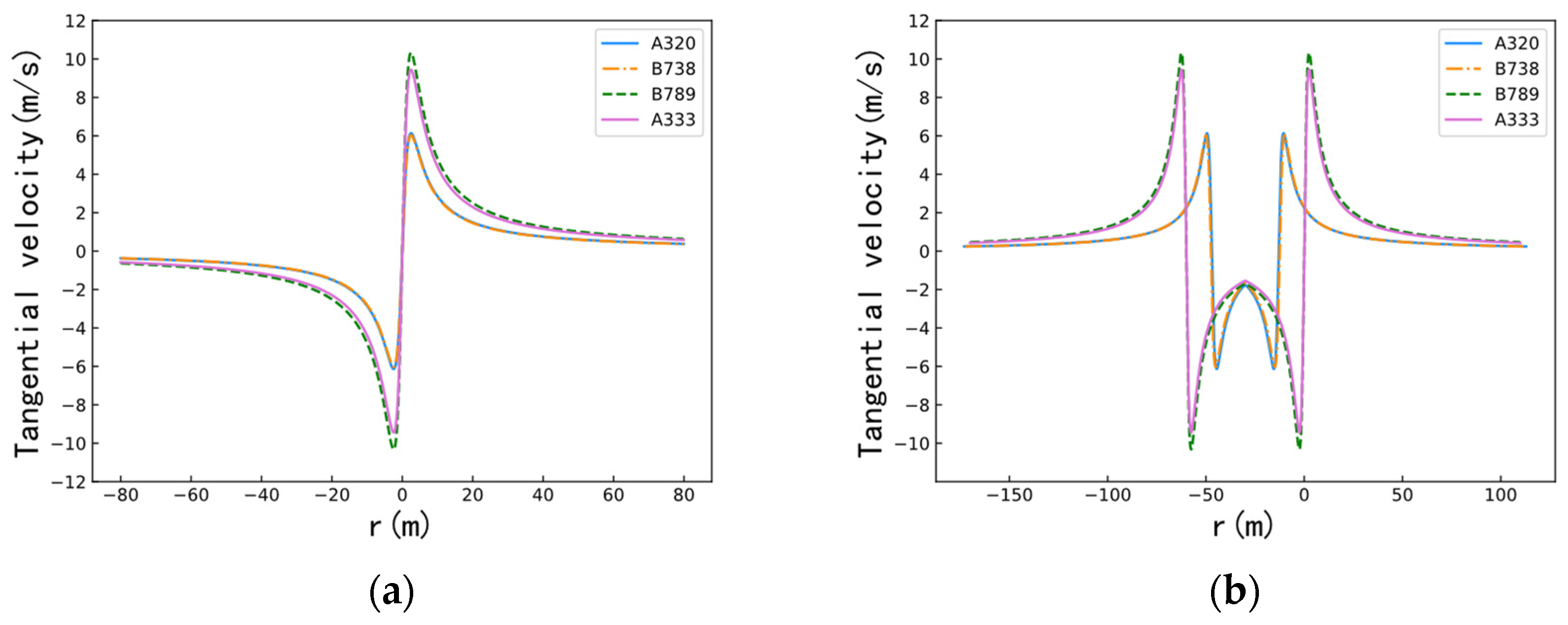
Figure 1. Induced velocities of different aircrafts at 174.95 kts. (a) Single vortex. (b) Twin vortex.
Aerospace 09 00633 g001
Figure 2. Force model of CRJ-900 and coordinate axis.
Aerospace 09 00633 g002
Figure 3. Rolling moment of CRJ-900 encountering wake vortex under time separation of 100 s at different velocities. (The velocity of A320 is 174.95 kts, and the counter-clockwise rolling moment is negative).
Aerospace 09 00633 g003
Figure 4. The wake-vortex evolution for different aircraft at different flight velocities. (a) A320. (b) B738. (c) B789. (d) A333.
Aerospace 09 00633 g004
Figure 5. Reduction in required flight separation with respect to ICAO standard at different aircraft velocities. (The legend is “velocity of leading aircraft/velocity of following aircraft”). (a) Case 1, deceleration is −2 m/s2. (b) Case 2, acceleration is 2 m/s2. (c) Case 3, deceleration is −2 m/s2. (d) Case 4, acceleration is 2 m/s2. (e) Case 5, front deceleration is −2 m/s2, following deceleration is −1 m/s2. (f) Case 6, front acceleration is 2 m/s2, following acceleration is 1 m/s2. (g) Case 7, front deceleration is −1 m/s2, following deceleration is −2 m/s2. (h) Case 8, front acceleration is 1 m/s2, following acceleration is 2 m/s2.
Aerospace 09 00633 g005aAerospace 09 00633 g005b
Figure 6. The front and following aircraft velocity profiles.
Aerospace 09 00633 g006
Figure 7. Dynamic separation change when CRJ-900 follows a medium aircraft.
Aerospace 09 00633 g007
Figure 8. Dynamic separation change when CRJ-900 follows a heavy aircraft.
Aerospace 09 00633 g008
Table 1. Parameters of aircraft.
Aircraft TypeWing Span (m)Final Approach Velocity
(m/s)
Maximum Landing Weight
(kg)
Wing Area (m2)Wake Vortex Classification
A32034.1071.9464,500122.6C
B73834.3171.9465,310125.0C
A33360.3071.94242,000361.6B
B78960.1071.94193,000325.0B
Table 2. Initial circulation of each aircraft at different velocities.
Aircraft TypeInitial Circulation at Different Flight Velocities (m2/s)
155.51
kts
157.45
kts
159.40
kts
161.34
kts
163.28
kts
165.23
kts
167.17
kts
169.11
kts
171.06
kts
173.00
kts
174.95
kts
A320167.93170.12172.31174.50176.69178.89181.10183.31185.51187.72189.94
B738169.98172.20174.41176.63178.85181.10183.31185.54187.77190.01192.26
A333282.58286.26289.94293.63297.33301.03304.73308.45312.17315.89319.63
B789258.37261.74265.11268.48271.86275.25278.64282.04285.44288.85292.27
Table 3. Turbulent dissipation rate of each aircraft at different velocities.
Aircraft TypeTurbulent Dissipation Rate at Different Flight Velocities (m2/s3)
155.51
kts
157.45
kts
159.40
kts
161.34
kts
163.28
kts
165.23
kts
167.17
kts
169.11
kts
171.06
kts
173.00
kts
174.95
kts
A3200.7680.7930.8190.8460.8730.9000.9280.9570.9861.0161.046
B7380.7540.7790.8040.8300.8570.8840.9120.9400.9680.9971.027
A3330.3800.3930.4050.4190.4320.4460.4590.4740.4880.5030.518
B7890.4380.4530.4670.4820.4980.5130.5300.5460.5630.5740.597
Table 4. Vortex dissipation rate of each aircraft at different velocities.
Aircraft TypeVortex Dissipation Rate at Different Flight Velocities (m1/3/s2/3)
155.51
kts
157.45
kts
159.40
kts
161.34
kts
163.28
kts
165.23
kts
167.17
kts
169.11
kts
171.06
kts
173.00
kts
174.95
kts
A3202.7452.7402.7342.7282.7232.7172.7122.7072.7012.6962.691
B7382.7182.7122.7072.7012.6962.6902.6852.6802.6742.6702.664
A3332.7592.7542.7482.7432.7372.7312.7262.7212.7152.7102.704
B7893.1503.1443.1283.1213.1253.1183.1123.1063.1003.0943.087
Table 5. Duration of near-vortex phase for each aircraft at different velocities.
Aircraft TypeDuration of Near Vortex Stage at Different Flight Velocities (s)
155.51
kts
157.45
kts
159.40
kts
161.34
kts
163.28
kts
165.23
kts
167.17
kts
169.11
kts
171.06
kts
173.00
kts
174.95
kts
A32010.1210.009.899.789.679.579.479.379.279.179.08
B73810.1910.089.979.869.759.649.549.449.349.249.15
A33318.7318.5118.3118.1017.9117.7117.5217.3417.1616.9816.81
B78918.4218.2118.0117.8117.6117.4217.2417.0616.8816.7016.53
Table 6. The rolling-moment coefficients of CRJ-900 at different velocities.
Dividing
Circulation
Rolling Moment Coefficients at Different Flight Velocities
136.07 kts139.96 kts143.84 kts147.73 kts151.62 kts155.51 kts159.40 kts163.28 kts167.17 kts171.06 kts174.95 kts
750.1120.1090.1060.1030.1010.0980.0960.0940.0910.0890.087
1150.1730.1680.1630.1590.1550.1510.1470.1440.1410.1370.134
1250.1880.1820.1770.1730.1680.1640.1600.1560.1530.1490.146
Table 7. Maximum rolling moment of CRJ-900 encountering wake vortex under TBS.
CRJ-900Maximum Rolling Moment of CRJ-900 Encountering Wake Vortex under TBS (KN·m)
A320B738A333B789
174.95 kts155.51 kts136.07 kts174.95 kts155.51 kts136.07 kts174.95 kts155.51 kts136.07 kts174.95 kts155.51 kts136.07 kts
174.95 kts−5.66−8.28−12.08−5.79−8.50−12.33−54.44−66.99−81.21−41.61−56.3471.66
RMC0.00120.00170.00250.00130.00180.00260.01130.01390.01680.00860.01160.0148
Publisher’s Note: MDPI stays neutral with regard to jurisdictional claims in published maps and institutional affiliations.