Article

Numerical Study on Improved Geometry of Outlet Pressure Ripple in Parallel 2D Piston Pumps

1
School of Engineering, Zhejiang University City College, Hangzhou 310000, China
2
Key Laboratory of Special Purpose Equipment and Advanced Manufacturing Technology, Ministry of Education & Zhejiang Province, Zhejiang University of Technology, Hangzhou 310014, China
*
Author to whom correspondence should be addressed.
Aerospace 2022, 9(10), 629; https://doi.org/10.3390/aerospace9100629
Submission received: 9 August 2022 / Revised: 20 October 2022 / Accepted: 20 October 2022 / Published: 21 October 2022

Abstract

:
Because the axial piston pump is often used in the aerospace and aviation fields, it is necessary to pay attention to its outlet pressure and flow characteristics. The parallel 2D piston pump proposed, based on the axial piston pump, has no structural flow ripple because it has a rail with a uniform acceleration and deceleration. Now, the pump is used in the special working conditions of the aerospace field, and it is required to meet the rated flow of 50 L/min, the rated load of 8 MPa, and an extremely low-pressure ripple. Based on CFD technology, this paper studies the pump’s outlet flow and pressure ripples through numerical simulation. According to the causes of the outlet pressure ripple, an improved geometry is determined to further reduce the outlet pressure ripple. Using a high-frequency pressure sensor to measure the outlet pressure ripple of the optimized pump prototype, it was found that the outlet pressure ripple rate of the prototype was only 6%. The parallel 2D piston pump has been proved by the simulation and test that its outlet pressure ripple is extremely low. However, it is not effective to reduce the outlet flow ripple by increasing the pre-pressure and reducing the backflow. In parallel 2D piston pumps, it is still necessary to find a new method to further reduce outlet pressure and flow ripples.

1. Introduction

Axial piston pumps that belong to hydraulic power units are widely used in the aviation and aerospace fields for advantages, such as a high power–weight ratio, strong load capacity and high efficiency [1,2,3]. However, in aviation and aerospace fields, the outlet pressure ripple of axial piston pumps is of particular concern because it can cause the vibration of pipelines and damage to hydraulic components, as well as endanger the stability of hydraulic systems [4,5,6].
In axial piston pumps, the pressure ripple is derived from flow ripples which are composed of the structural flow ripple and the compressible flow ripple [7,8]. The structural flow ripple is determined by its own mechanical structure [9]. Under ideal conditions, the output flow curve of a single piston is a sinusoid, and the superposition of multiple sinusoids cannot form a straight line without fluctuations, so the axial piston pump cannot eliminate the structural flow ripple. The compressible flow ripple is caused by the backflow that refers to the phenomenon in which the oil flows back from the outlet to the piston chamber [10]. When the piston chamber is ready to discharge oil, the pressure in the chamber is lower than that of the outlet. Then, the piston chamber connects with the outlet through the valve plate, and the oil enters the piston chamber from the outlet to help the oil pressurization in the chamber [11,12]. When the oil pressure in the chamber is higher than the outlet, the piston chamber begins to drain oil.
There are many studies on the flow ripple, such as the work by Ma where they optimized the design of the valve plate using a mathematical model and a computational fluid dynamics (CFD) simulation to reduce the compressible flow ripple [13,14]. Bergada studied leakages in four types of the friction pairs of axial piston pumps through mathematical modeling and researched the effect of leakages on the flow ripple [15]. In order to find the optimal design of the valve plate faster, Song proposed that the optimization procedure for the pre-compression volume and the swash-plate cross angle with a relief groove had been greatly simplified by adopting the developed parameter-selection criteria from the simulation results [4]. Zhang analyzed the flow-dynamics characteristics of an axial piston pump based on the improved CFD simulation, and test results showed that the compressible flow ripple made up 88% of the flow ripple [16]. Zhu came up with a solution that involved a kind of double-swash-plate hydraulic axial-piston electric-motor pump with port valves, where a cylinder rotates along with the port valves, which is different from the conventional port-valving pump, in which the swash-plate rotates and the cylinder is mounted in the casing [17]. The valve distribution structure can effectively reduce the backflow, thereby reducing the compressible flow ripple. Zhong used an independent metering valve-control hydraulic system (IMVCHS) to deal with the flow and pressure ripples generated by the axial piston pump and improve the stability of the fluid [18]. Swarnava conducted an investigation of a novel positive-displacement axial-piston machine using a bent cylinder sleeve configuration, and groove geometry was chosen primarily to reduce flow ripple [19]. He further reduced the outlet flow and pressure ripples by combining two axial piston pumps into one and studied the influence of structural parameters on the ripples through simulation [20].
However, the above studies are all for the compressible flow ripple, and there is still little research on how to reduce the structural flow ripple through mechanical designs. The 2D pump, using the guiding rail with a uniform acceleration and a uniform deceleration, was proposed by our team in order to eliminate the structural flow ripple [21,22]. Figure 1a demonstrates the mechanical design of a parallel 2D piston pump, which consists of two high-speed 2D piston pumps mechanically connected in series. The transmission mechanism of the high-speed 2D piston pump is a mechanism composed of the rollers and the guiding rail, as shown in Figure 1b. When the cone rollers of the driving roller and the balancing roller are rolling on the guide rail, the driving roller and balancing roller rotates in a reciprocating linear motion. The output flow curve of the high-speed 2D piston pump is a triangular curve, and the working principle and output flow characteristics of the 2D pump have been described in detail in References [23,24] and will not be described here. Because the installation positions of the two 2D pumps in the parallel 2D piston pump have a phase difference of 45 deg, their output flow curves can compensate each other and become a straight line [24].
A pump with a rated flow rate of 50 L/min, where L is the volume unit and 1 L is equal to 1 dm3, a rated load pressure of 8 MPa, and a small outlet pressure ripple is re-quired for the special working conditions of the aerospace field. A pump that meets the above requirements was designed according to the structural design of the parallel 2D piston pump shown in Figure 1. Figure 2 shows the outlet flows of the pump and the corresponding four working chambers, where 0 deg corresponds to the state of Figure 1. This pump needs to be further optimized because a smaller outlet pressure pulsation is required. Shentu studied the outlet pressure ripple of a parallel 2D pump by CFD simulations and experimental studies [24]. However, she did not propose a method to optimize the pressure ripple, and her experiments used conventional pressure sensors instead of high-frequency pressure sensors, so the experimental results were not satisfactory.
The parallel 2D piston pump, a hydraulic pump without a structural flow ripple, is a great innovation, but unfortunately there is no research to measure its outlet flow and pressure ripples, and no solution to further reduce its ripples has been proposed [25]. This paper focuses on determining an improved geometric design to reduce the outlet pressure ripple of the parallel 2D piston pump by using a numerical simulation method. The CFD model of the parallel 2D piston pump was built, and its geometric model, grid model, numerical strategy, and boundary conditions are introduced in detail. Pressure ripples and output flow ripples of the four working chambers and parallel 2D piston pump are analyzed and the optimized design is determined according to the simulation. Finally, experimental results are presented as an example to verify the simulation and the improved geometric design.

2. Description of CFD Model

In this chapter, the description of the CFD model is split into four parts: in order, the fluid zone’s geometric model, the grid model, the numerical strategy, and the boundary conditions.

2.1. Geometric Model

Figure 3 shows the fluid zone extracted from the mechanical structure of the parallel 2D piston pump in Figure 1. This fluid zone is divided into 4 parts: in order, an inlet zone, an outlet zone, a left pump unit, and a right pump unit. Oil enters the pump shell through the back cover, and then enters the right pump unit through kidney-shaped channels. The remaining oil enters the cylindrical chamber in the middle through the kidney-shaped channels and the circular channels, and then enters the left pump unit through the kidney-shaped channels. Oil discharged from the left and right pump units first gathers in two annular chambers on both sides, and then flows out through the outlet in the middle.

2.2. Grid Model

The grid model of the parallel 2D piston pump is also divided into four parts: two pump units, an inlet, and an outlet, according to the geometric model of the fluid zone. Figure 4a,b show the grid models of the left and right pump units and their geometric dimensions. A pump unit is divided into four parts, which are a left chamber (LC), a left distribution part (LDP), a right distribution part (RDP), and a right chamber (RC). The LC and RC of the left pump unit shown in Figure 4a are of a medium size, while the LC and RC of the right pump unit shown in Figure 4b are of maximum and minimum size, respectively. The dimensions marked in the figures are in mm. According to the working principle of 2D piston pumps, the LC and RC need to expand and contract, while the LDP and RDP need to displace and rotate.
This paper uses the dynamic mesh to simulate the above motion and takes the left pump unit as an example to describe boundary settings, as shown in Figure 5. The LC and RC do not rotate, but expand and contract, so their two side walls, such as the LLCMW and LLCI, are selected as moving walls. Because the LDP and RDP are not deformed and only rotated and displaced, they are selected as rigid body zones to move according to the set dynamic-mesh procedure. The LC and LDP also need to set the boundaries of contact between them as an interface before they can interact with each other.
Figure 6 shows the dimensions and boundary settings of the inlet fluid zone. Because the influence of insufficient sucking oil on the outlet flow ripple is not considered in this study, the inlet pressure needs to increase to ensuring there is sufficient sucking oil in both the simulation and the experiment. The inlet of the inlet fluid zone is chosen as a pressure inlet and the outlets are set as interfaces. It should be noted here that, taking the outlets on the left as an example, they must establish the interfaces with the contact walls of the LDP and RDP, respectively.
The dimensions and boundary settings of the outlet fluid zone are similar to those of the inlet fluid zone, as shown in Figure 7a. However, the boundary of the outlet cannot be set as a pressure outlet. Because the pressure outlet can change the outlet to the set pressure, the pressure ripple cannot be detected. In order to obtain the outlet pressure ripple, an additional section of the outlet pipe is required at the outlet, as shown in Figure 7b. The outlet pipe is connected to a throttle valve. The load pressure of the pump is adjusted by changing the throttle area of the throttle valve. The downstream part of the throttle valve is provided with a pressure outlet. The sizes of the outlet pipe are based on the actual working conditions of the pump and are completely consistent with the experiment.
Figure 8 shows the grid model of the parallel 2D piston pump formed by combining the four parts. The averaged outlet pressures are compared by increasing the number of mesh elements with a similar quality of the mesh element, as shown in Figure 9. From 2.6 × 10⁵ mesh elements to 4.9 × 10⁵ mesh elements, the averaged outlet pressure changes by 0.625%. From 4.9 × 10⁵ mesh elements to 7.5 × 10⁵ mesh elements, the averaged outlet pressure changes by 0.25%. As such, a grid with a number of 7.5 × 10⁵ elements is chosen as the computational model.

2.3. Numerical Strategy

It is a normal choice to use the laws of mass conservation and momentum conservation for numerical strategies in the CFD simulation. These conservation laws can be described as the following equations
ρ t + ρ u x x + ρ u y y + ρ u z z = 0 ,
D u x D t = 1 ρ p x + v ( 2 u x x 2 + 2 u x y 2 + 2 u x z 2 ) + R ,
D u y D t = 1 ρ p y + v ( 2 u y x 2 + 2 u y y 2 + 2 u y z 2 ) + T ,
D u z D t = 1 ρ p z + v ( 2 u z x 2 + 2 u z y 2 + 2 u z z 2 ) + Z ,
where t is the time, p, ux, uy, and uz are fluid’s pressure and velocities in the xyz directions, respectively, and R, T, and Z are body forces acting on the unit micelle in the xyz directions, respectively. ρ is oil density and υ is oil kinematic viscosity.
Due to the phenomena of backflow, pressure overshoot in the chamber, and because pressure ripples are closely related to the oil compressibility, the oil compressibility must be considered for the numerical simulation of 2D piston pumps. If the oil is incompressible, oil density is constant. This means that the transmission speed of the pressure wave is infinite, and it is unreasonable. The essence of compressible fluid is to correct the density by pressure and the elastic modulus K, and the relationship between them can be described as:
ρ = ρ 0 ( 1 ( p p 0 ) / K ) ,
where p0 is an ambient pressure of 1.01 bars and ρ0 is the corresponding density under the ambient pressure. The speed of sound c is calculated as
c = K ρ = K ( p p 0 ) ρ 0 ,
The renormalization group (RNG) k-ε model is used as the turbulence model for this simulation. The standard k-ε model proposed by Launder and Spalding is widely used in engineering CFD calculations because of its wide application range, ability to save computing resources, and suitable accuracy [26]. The RNG k-ε model is derived from the standard k-ε model using a statistical method called renormalization group theory [27]. The jet is extremely fast when the working chamber starts to discharge oil. The RNG model adds a term to its ε equation, improving the accuracy of high-velocity flows. This is the reason why the RNG k-ε model is chosen as the turbulence model.
Solution methods are required for solving the numerical calculation through the commercial software FLUENT. The coupled scheme is used for the numerical calculation. A second-order scheme is chosen for the modeling of the pressure. A second-order upwind scheme is chosen for the modeling of the density and momentum. A first-order upwind scheme is chosen for the modeling of the turbulence.

2.4. Boundary Conditions

Because the working conditions of the parallel 2D piston pump was determined, it needs to provide a flow of 50 L/min under a load of 8 MPa. The displacement of the parallel 2D piston pump is designed to be 10.24 mL/rev, so the rated rotational speed should be 5000 rpm.
One disadvantage of using a throttle valve to modulate pressure is that it cannot be accurately controlled. Therefore, the target is that the pressure of the outlet is close to 8 MPa in the simulation, and the cross-sectional area of the throttle valve is selected to be 5.3 mm2. The pressure inlet is consistent with the test, the pressure is 4 bars, and the pressure outlet is set to a normal pressure.
For the convenience of understanding, the left chamber of the left pump unit is denoted by the symbol LLC, and the left distribution part of the left pump unit is denoted by the symbol LLDP, and so on. The most important thing is the setting of the dynamic mesh, and its rotation direction and boundary movement must correspond. Taking Figure 10 as an example, there are four working chambers and four distribution parts, from left to right: LLC, LLDP, LRDP, LRC, RLC, RLDP, RRDP, and RRC. The velocity of the boundary is based on the movement of the 2D piston, which has been studied in [28,29]. According to the Cartesian coordinate system in Figure 8, the velocity v1 of the LLCMW and LRCMW and the velocity v2 of LLCI, LLDP, LRDP, and LRCI can be expressed as
v 1 = v 2 = { 16 ω 2 L s π 2 ( π 4 ω t ) 0 < t π 2 ω 16 ω 2 L s π 2 ( t 3 π 4 ω ) π 2 ω < t 3 π 4 ω ,
where ω is the rotational angular velocity of the 2D piston and Ls is the stroke of the 2D piston, designed to be 2.5 mm. The velocity v3 of RLCMW and RRCMW and the velocity v4 of RLCI, RLDP, RRDP, and RRCI can be expressed as
v 3 = v 4 = { 16 ω 2 L s π 2 t 0 < t π 4 ω 16 ω 2 L s π 2 ( π 2 ω t ) π 4 ω < t 3 π 4 ω 16 ω 2 L s π 2 ( t π ω ) 3 π 4 ω < t π ω ,
LLDP, LRDP, RLDP, and RRDP also rotate at the angular velocity of ω that is expressed by Equation (9),
ω = n 60 2 π ,
where n is the rotational speed in rpm and the direction of rotation conforms to the right-hand rule.
Aviation hydraulic oil at 40 °C is used as the medium. Under the ambient pressure of 1.01 bars, given liquid has a kinematic viscosity of 13.84 × 10⁻⁶ m2/s, an elastic modulus of 1000 MPa, and a density of 850 kg/m3.
Finally, the body force Z is also considered to be −9.8 m/s2.

3. Numerical Calculation Results

Firstly, the outlet pressure ripple and flow ripple of the originally designed parallel 2D piston pump are obtained by numerical calculation. The reasons for the outlet pressure and flow ripple are analyzed by researching the output flow and chamber pressure of the four working chambers. Then, the design of the parallel 2D piston pump is optimized according to these causes, and the outlet pressure and flow ripple of the optimized 2D pump are studied and compared with those before the improved geometry.

3.1. Before Improved Geometry

The parallel 2D piston pump has four working chambers that work in exactly the same way but with different phases. Therefore, the LLC is used as an example to analyze the chamber pressure and outlet flow of the working chamber. Figure 11 shows the chamber pressure in the LLC. The pressure decline marked at position 1 in Figure 10 is different from the chamber pressure of axial piston pumps. In reference [24], it is believed that this is oil shock caused by backflow, but this paper has a different explanation. Position 1 is the point at which the moving parts switch from a uniform acceleration to a uniform deceleration. When the 2D piston starts to push the oil with a uniform deceleration, the oil continues to accelerate due to inertia, resulting in the oil-pressure decline. However, this interpretation is not supported by previous simulation research of the 2D piston pump, so a single pump unit is simulated to verify this interpretation. The explanation for why the pressure increases at position 2 is that the suction and discharge oil windows are designed too small. At this time, the LLC is in a closed state and the volume of the LLC is still decreasing, causing the chamber pressure to rise. There is no immediate rise in the chamber pressure when the LLC begins to contract, as marked at position 3 in Figure 10. This is also because the suction and discharge oil windows are designed too small. When the 2D piston rotates close to 180 deg and the LLC is not connected to the suction oil window, the LLC is still expanding. By the time the LLC compresses, more volume needs to be compressed for the rise in chamber pressure.
The outlet and inlet flow curves of the LLC were designed to be triangular, as shown in Figure 12, and the numerical calculation results are basically consistent with the design. The reason for the small size of the inlet and outlet windows mentioned above is to let the LLC pre-pressurize before draining oil to reduce backflow. However, the LLC still has a large backflow in the early stage of discharging oil, which is different from the original design. A pump unit will be simulated later to explore the differences between the parallel 2D piston pump and the single pump unit.
The grid model of the pump unit is shown in Figure 13. Both the inlets and outlets are set as the pressure inlet and outlet, and the set pressures are 0.4 MPa and 8 Mpa, respectively.
Figure 14 shows the pressure in the left chamber and the outlet flow of the pump unit. The pressure in the left chamber of the pump unit, and that of the LLC, are completely inconsistent. Firstly, the pressure fluctuation disappears, and there is only a pressure decline of nearly 45°, which is far less than the pressure decline in the previous parallel 2D piston pump simulation. This shows that the inertia caused by the change of acceleration is not the main reason for the pressure decline. Secondly, at the beginning of the oil discharge, the pressure has a high peak; however, at the end of the oil discharge, the pressure peak is higher than that of the LLC. It can be seen from Figure 14b that the backflow of the pump under this design should be very small when the load is 8 MPa. This means that the outlet pressure of the single pump unit is higher than 8 MPa in the parallel 2D piston pump.
In order to study the outlet load of the pump unit in the parallel 2D piston pump, the pressure distributions of the outlet flow zone are plotted as shown in Figure 15. In the parallel 2D piston pump, the symmetrical distribution of the left and right pump units can cause the oil to move left and right, so that the outlet load fluctuation of the pump unit can have an effect on the pressure fluctuation and pressure decline in the chamber. The influence of the symmetrical distribution of the left and right pump units on chamber pressure will continue to be a concern.
The pressure distributions of the four working chambers and the pump outlet are shown in Figure 16. It is evident from the figure that there is no correlation between the chamber pressure and the pump outlet pressure. Their pressure declines seem to correspond, but this is not actually inferred from their maintained rotational angles. However, the pressure declines in the chambers may be transmitted to the outlet and exacerbate the outlet pressure ripple due to the compressibility.
Figure 17 shows the outlet flows of the four working chambers and the parallel 2D piston pump. Comparing Figure 16 and Figure 17, it is found that the curves of the outlet pressure and flow of the pump are basically the same. This means that the pump outlet pressure ripple comes from the change of the outlet flow. The outlet flow ripple of the pump comes from the backflow that occurs in the four working chambers. In order to reduce the outlet flow ripple, the backflow existing in the working chamber must be reduced.
The areas for improvement are summarized as follows:
1. The pre-pressure of the working chamber needs to be higher.
2. When the working chamber starts to compress, the chamber pressure should rise immediately.
3. When the working chamber finishes compression, the pressure peak in the chamber should decrease.

3.2. After Improved Geometry

Figure 18 shows an optimized design for the parallel 2D piston pump. Two structures have been optimized: one is to increase the area of the oil inlet windows, and the other is to rotate the oil outlet windows by 2 deg towards the rotation direction of the pump.
The chamber pressure and flow of the optimized LLC are described in Figure 19. The optimized chamber pressure eliminates the pressure rise at the end of the discharging oil and reduces the flow backflow at the beginning of the discharging oil. However, when the LLC begins to discharge oil, the pressure rise is still delayed, and a pressure peak appears. The above two problems are caused by the circular window, which can cause the gradient of the increase in the connection area to be too small when it is just connected. Changing the circular window to a rectangular one can solve these problems.
Finally, two comparisons of the outlet flows and the pressures of the pump before and after the improved geometry are shown in Figure 20. The optimized pump has an increased output flow due to reduced backflow. The output flow and pressure ripples can be represented as the ratio of the difference between the maximum and minimum values compared to the average value. The output flow ripple of the optimized pump changed from 8.1% to 7%, compared with that before the improved geometry, and the pressure ripple changed from 12.5% to 11%. In the numerical calculation, the output flow and pressure ripples in the optimized parallel 2D piston pump are reduced by reducing the backflow. However, reducing the flow ripple by pre-pressurizing interferes the superposition of the output flows of the two pump units, which is the source of the outlet flow and pressure ripples.

4. Experiments

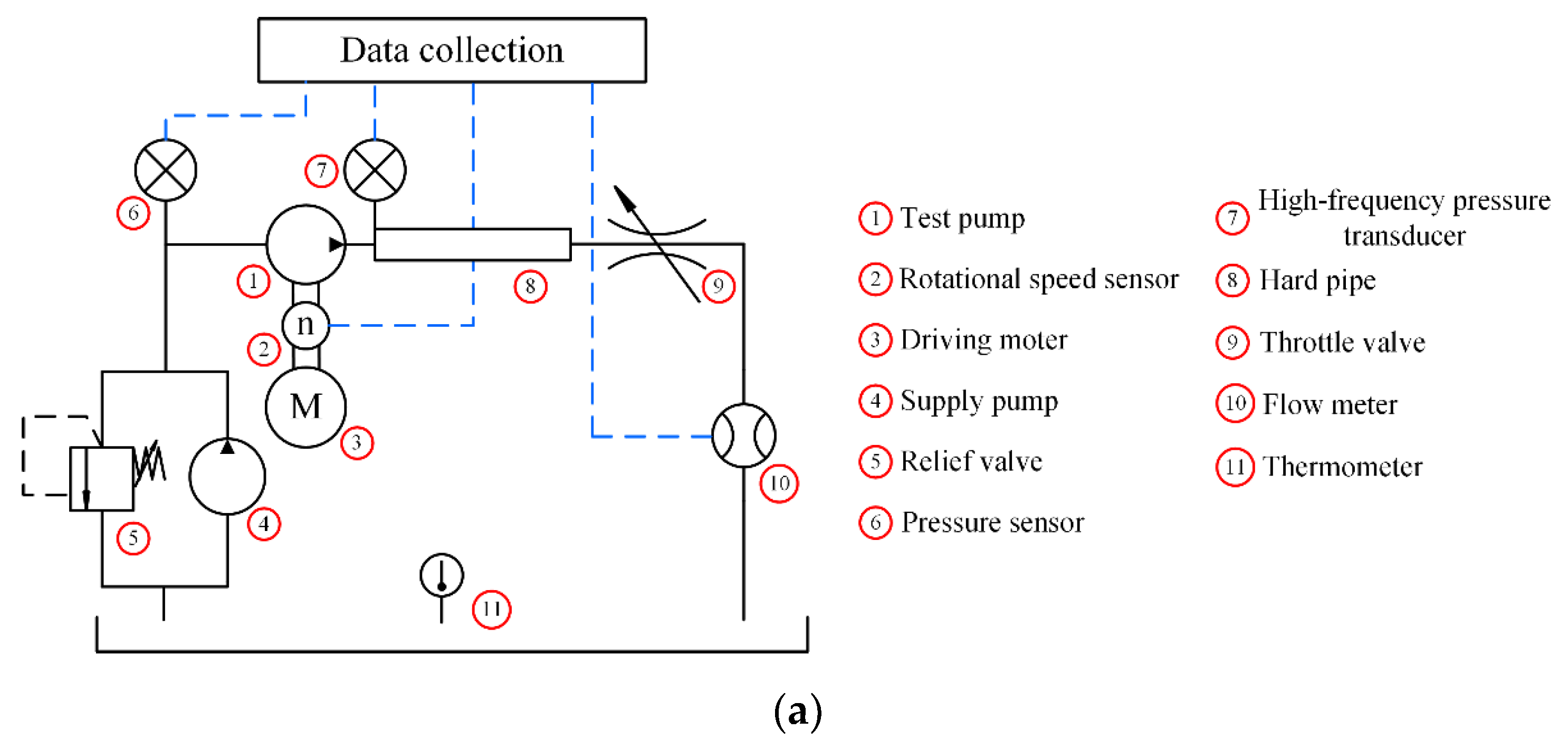
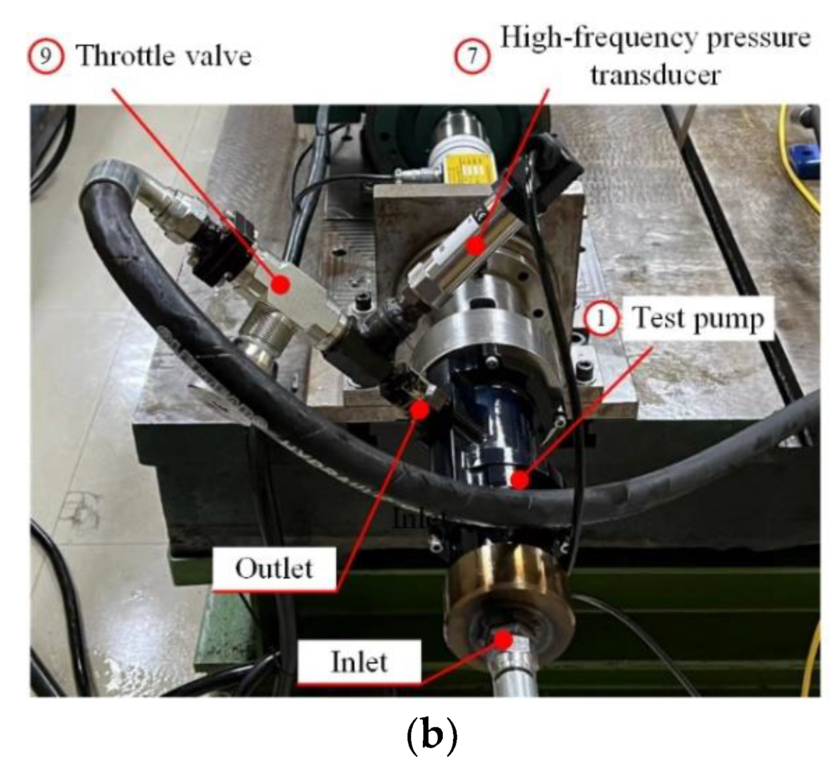
The test system takes into account the actual application environment and sets the outlet as a 5 cm hard pipe, as shown in Figure 21. The test system is equipped with a supply oil pump and an inlet pressure sensor to ensure the sufficient sucking oil of the test pump. A rotational speed sensor is installed between the motor and the test pump to monitor the rotational speed of the test pump in real time. The outlet pressure sensor is placed at the outlet of the test pump, consistent with the simulation. A throttle valve is set downstream of the hard pipe to change the load pressure of the test pump. A flowmeter is installed downstream of the throttle valve to measure the outlet flow. The oil tank is equipped with a thermometer to detect the oil temperature, in order to prevent the test results from being disturbed by the oil temperature rise.
The reason why this test cannot verify the flow ripple is that the flowmeter cannot measure the high-frequency flow [30,31], so only the outlet pressure ripple is detected for the test pump. The key to the detection of the pressure ripple is to select a high-frequency pressure sensor. In this experiment, the pressure sensor of the HM90(10 MPa)-H3-3-V2-F2 is selected, and its parameters are shown in Table 1.
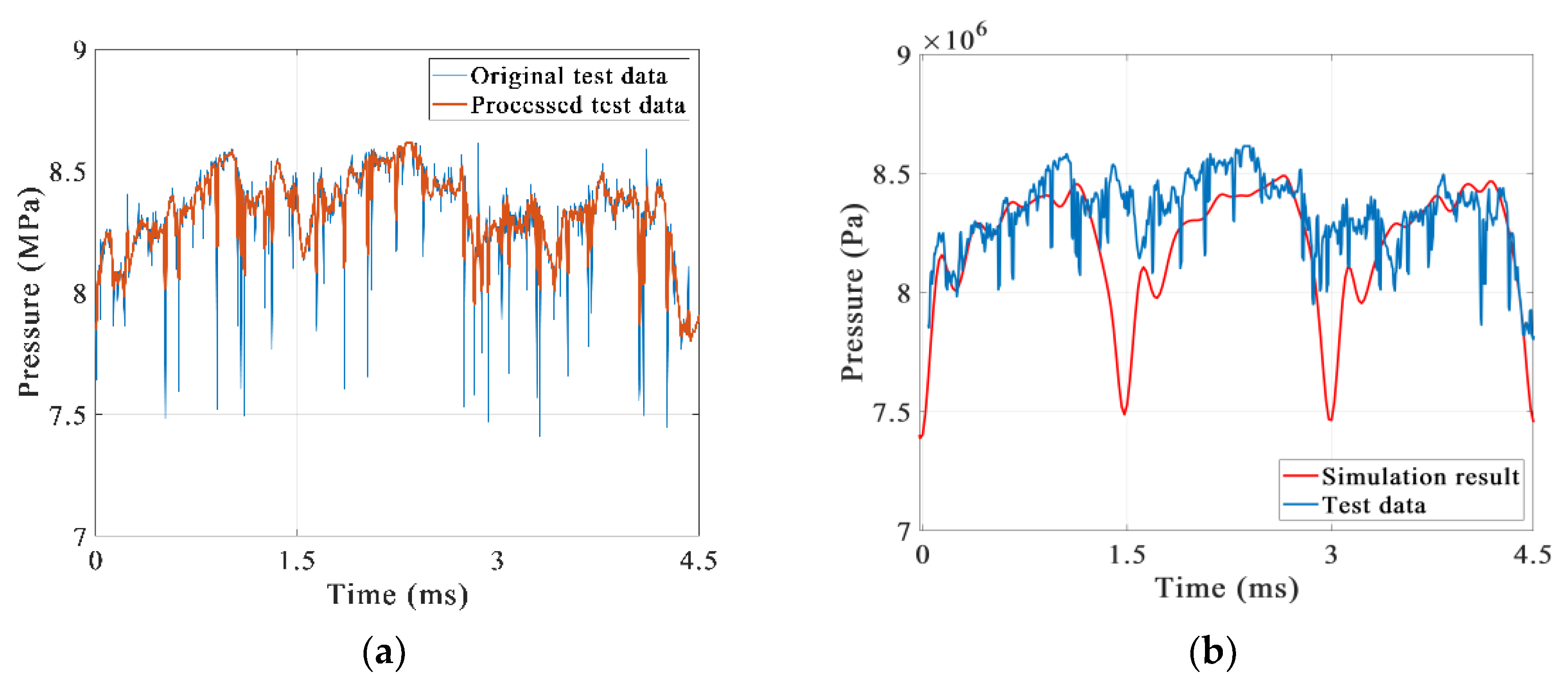
At a rotational speed of 5000 rpm and a load of 8 MPa, the outlet pressure ripple data of the test pump are measured through multiple tests. The original data measured by the experiment contains many interference signals, so the original data are processed by low-pass filtering and three-point averaging. The comparison between the processed data and the original data is shown in Figure 22a. Then, the processed experimental data and the simulation are compared, as shown in Figure 22b, and the following conclusions are drawn. Firstly, the experimental result and the numerical simulation are relatively consistent, especially in the prediction of the pressure ripple period. Secondly, after studying the amplitude–frequency characteristics of the test data and simulation result, it is found that the main frequency of the simulation result is 667 Hz, and the main frequency of the experimental data is 600 Hz. The main frequencies of the two are relatively close, but their amplitudes are quite different, as shown in Figure 23. Finally, the prototype of the parallel two-dimensional piston pump is tested and proves to have a low-pressure ripple of only 6%.
However, there are also differences between the experimental data and the simulation result, especially in the magnitude of the pressure drop. Two explanations are proposed for this. The first is that the installation position of the pressure sensor in the tests is different from the measuring position of the simulation. The former is installed on the side of the pipeline, and the latter is the outlet of the pump. Secondly, the distribution windows of the prototype in the experiment are designed to be rectangular, while the distribution windows in the simulation are still circular, which also leads to a difference.

5. Discussion and Conclusions

In this paper, the outlet pressure ripple of a parallel 2D piston pump is studied by numerical modeling and simulation. In the simulation, by analyzing the pressure and outlet flow of the working chambers, it is explained that the outlet pressure ripple of the pump comes from the flow ripple, which is derived from the backflow that occurs when the oil is discharged from the working chamber. To reduce backflow, the mechanical structures of the 2D pump have been optimized. In the end, the accuracy of the numerical simulation was verified and the outlet pressure ripple rate of the parallel 2D piston pump was measured by testing the outlet pressure ripple of the optimized prototype. The conclusions are as follows:
1. Under the operating conditions with a rotational speed of 5000 rpm and a load pressure of 8 MPa, the measured pressure ripple rate of the optimized parallel 2D piston pump prototype is only 6%.
2. The outlet pressure ripple is indeed derived from the outlet flow ripple. The outlet flow ripple can be reduced by reducing the outlet flow ripple, so the mechanical structure of the parallel 2D piston pump, which is designed to eliminate the structural flow ripple, has a great advantage in a low outlet flow ripple.
3. By adding pre-pressure, the backflow of the working chamber can be reduced. However, in the parallel 2D piston pump, the effect on the outlet flow ripple is not significant by reducing the backflow of the working chamber.
In future research, we will continue to maintain the advantage of the 2D piston pump and propose a 2D piston pump with an extremely low-pressure ripple under a load pressure of 28 MPa by modifying the rail curve. In addition, through simulation, it was found that the pressure in the chamber is much higher than the load pressure when the oil is discharged from the working chamber, which greatly effects the mechanical efficiency of the pump and will be continue to be researched. Finally, measur outlet flow ripple of the parallel 2D piston pump are also in progress, and the geometry of the numerical model of the parallel 2D pump will also more closely match the geometry of the experiment.

Author Contributions

Writing—original draft preparation, Y.H. and W.S.; writing—review and editing, Q.L.; visualization, L.L.; supervision, J.R.; funding acquisition, C.D. All authors have read and agreed to the published version of the manuscript.

Funding

This research was funded by the National Natural Science Foundation of China, grant number 51805480, by the Zhejiang Provincial Natural Science Foundation, grant number LY21E050013.

Conflicts of Interest

The authors declare no conflict of interest.

References

  1. Chao, Q.; Zhang, J.; Xu, B.; Huang, H.; Pan, M. A review of high-speed electro-hydrostatic actuator pumps in aerospace applications: Challenges and solutions. J. Mech. Des. 2019, 141, 050801. [Google Scholar] [CrossRef] [Green Version]
  2. Robbins, D.; Bobalik, J.; De Stena, D.; Martin, N.; Plag, K.; Rail, K.; Wall, K. F-35 subsystems design, development & verification. In Proceedings of the 2018 Aviation Technology Integration Operation Conference, Atlanta, Georgia, 25–29 June 2018; p. 3518. [Google Scholar]
  3. Yang, H.Y.; Pan, M. Engineering research in fluid power: A review. J. Zhejiang Univ.-Sci. A 2015, 16, 427–442. [Google Scholar] [CrossRef] [Green Version]
  4. Song, Y. Investigation on Test Method and Noise Reduction Structure with Large Operating Conditions for Piston Pump Flow Rate. Ph.D. Dissertation, Zhejiang University, Hangzhou, China, 2013. [Google Scholar]
  5. Wu, S.; Yu, B.; Jiao, Z.; Shang, Y.; Luk, P. Preliminary design and multi-objective optimization of electro-hydrostatic actuator. Proc. Inst. Mech. Eng. Part G J. Aerosp. Eng. 2017, 231, 1258–1268. [Google Scholar] [CrossRef]
  6. Battarra, M.; Mucchi, E. On the relation between vane geometry and theoretical flow ripple in balanced vane pumps. Mech. Mach. Theory 2020, 146, 103736. [Google Scholar] [CrossRef]
  7. Edge, K.; Darling, J. The pumping dynamics of swash plate piston pumps. Journal of Dynamic Systems. Meas. Control 1989, 111, 307–312. [Google Scholar] [CrossRef]
  8. Xu, B.; Hu, M.; Zhang, J. Impact of typical steady-state conditions and transient conditions on flow ripple and its test accuracy for axial piston pump. Chin. J. Mech. Eng. 2015, 28, 1012–1022. [Google Scholar] [CrossRef]
  9. Edge, K. A theoretical model of axial piston pump flow ripple. In Proceedings of the First Bath International Fluid Power Workshop, Bath, UK, 8 September 1988; pp. 113–136. [Google Scholar]
  10. Sanchen, G. Auslegung von Axialkolbenpumpen in Schrägscheibenbauweise mit Hilfe der numerischen Simulation; Shaker: Harrodsburg, KY, USA, 2003. [Google Scholar]
  11. Pan, Y.; Chen, A.; Wang, Z. Fluid Dynamic Characteristics and Flow Distribution Structure Optimization of Axial Piston Pump Considering Cavitation Bubble Evolution. J. Appl. Fluid Mech. 2021, 14, 1603–1616. [Google Scholar]
  12. Guo, S.; Chen, J.; Lu, Y.; Wang, Y.; Dong, H. Hydraulic piston pump in civil aircraft: Current status, future directions and critical technologies. Chin. J. Aeronaut. 2020, 33, 16–30. [Google Scholar]
  13. Jien, M. Study on Flow Ripple and Valve Plate Optimization of Axial Piston Pump; Zhejiang University: Hangzhou, China, 2009. [Google Scholar]
  14. Ma, J.; Xu, B.; Yang, H. Modeling and experiment study on fluid character of axial piston pump. Trans. Chin. Soc. Agric. Mach. 2010, 41, 188–194. [Google Scholar]
  15. Bergada, J.; Kumar, S.; Davies, D.L.; Watton, J. A complete analysis of axial piston pump leakage and output flow ripples. Appl. Math. Model. 2012, 36, 1731–1751. [Google Scholar] [CrossRef]
  16. Zhang, B.; Ma, J.; Hong, H.; Yang, H.; Fang, Y. Analysis of the flow dynamics characteristics of an axial piston pump based on the computational fluid dynamics method. Eng. Appl. Comput. Fluid Mech. 2017, 11, 86–95. [Google Scholar] [CrossRef] [Green Version]
  17. Zhu, B. Research on the Flow Distribution Characteristics and Variable Principle of the Double- swashplate Hydraulic Axial Piston Electric Motor Pump with Port Valves. J. Mech. Eng. 2018, 54, 220–234. [Google Scholar] [CrossRef]
  18. Zhong, Q.; Zhang, B.; Bao, H.-M.; Hong, H.-C.; Ma, J.-E.; Ren, Y.; Fung, R.-F. Analysis of pressure and flow compound control characteristics of an independent metering hydraulic system based on a two-level fuzzy controller. J. Zhejiang Univ.-Sci. A 2019, 20, 184–200. [Google Scholar] [CrossRef]
  19. Mukherjee, S.; Masia, A.; Bronson, M.; Shang, L.; Vacca, A. A Novel Positive Displacement Axial Piston Machine with Bent Cylinder Sleeves. In Proceedings of the ASME/BATH 2021 Symposium on Fluid Power and Motion Control, Online, 19–21 October 2021; p. V001T01A024. [Google Scholar]
  20. He, T.; Li, Z.; Deng, H.; Chen, Q.; Wang, C.; Zhao, K. Flow characteristics analysis of a balanced valve distribution double-row axial piston pump. Mech. Sci. 2022, 13, 207–223. [Google Scholar] [CrossRef]
  21. Jin, D.C.; Ruan, J.; Li, S.; Meng, B.; Wang, L.-F. Modelling and validation of a roller-cam rail mechanism used in a 2D piston pump. J. Zhejiang Univ.-Sci. A 2019, 20, 201–217. [Google Scholar] [CrossRef]
  22. Xing, T.; Xu, Y.; Ruan, J. Two-dimensional piston pump: Principle, design, and testing for aviation fuel pumps. Chin. J. Aeronaut. 2020, 33, 1349–1360. [Google Scholar]
  23. Huang, Y.; Ding, C.; Wang, H.; Ruan, J. Numerical and experimental study on the churning losses of 2D high-speed piston pumps. Eng. Appl. Comput. Fluid Mech. 2020, 14, 764–777. [Google Scholar] [CrossRef]
  24. Shentu, S.; Ruan, J.; Qian, J.; Meng, B.; Wang, L.; Guo, S. Study of flow ripple characteristics in an innovative two-dimensional fuel piston pump. J. Braz. Soc. Mech. Sci. Eng. 2019, 41, 464. [Google Scholar] [CrossRef]
  25. Zhang, C.; Zhu, C.; Meng, B.; Li, S. Challenges and Solutions for High-Speed Aviation Piston Pumps: A Review. Aerospace 2021, 8, 392. [Google Scholar] [CrossRef]
  26. Launder, B.E.; Spalding, D.B. The numerical computation of turbulent flows. Comput. Methods Appl. Mech. Eng. 1974, 3, 269–289. [Google Scholar] [CrossRef]
  27. Yakhot, V.; Orszag, S.A. Renormalization group analysis of turbulence. I. Basic theory. J. Sci. Comput. 1986, 1, 3–51. [Google Scholar] [CrossRef]
  28. Huang, Y.; Ruan, J.; Chen, Y.; Ding, C.; Li, S. Research on the Volumetric Efficiency of 2D Piston Pumps with a Balanced Force. Energies 2020, 13, 4796. [Google Scholar] [CrossRef]
  29. Huang, Y.; Ruan, J.; Ding, C.; Li, S. Effect of clearance on volumetric efficiency in 2D piston pumps. Adv. Mech. Eng. 2021, 13, 1–12. [Google Scholar] [CrossRef]
  30. Edge, K.; Johnston, D. The ‘secondary source’ method for the measurement of pump pressure ripple characteristics Part 1: Description of method. Proc. Inst. Mech. Eng. Part A J. Power Energy 1990, 204, 33–40. [Google Scholar] [CrossRef]
  31. Edge, K.; Boston, O.; Xiao, K.; Longvill, K.; Burrows, K. Pressure pulsations in reciprocating pump piping systems Part 2: Experimental investigations and model validation. Proc. Inst. Mech. Eng. Part I J. Syst. Control. Eng. 1997, 211, 239–250. [Google Scholar] [CrossRef]
Figure 1. (a) The mechanical design of a parallel 2D piston pump and (b) working principle of the rollers and the guiding rail.
Aerospace 09 00629 g001
Figure 2. The theoretical outlet flow of the parallel 2D piston pump.
Aerospace 09 00629 g002
Figure 3. The fluid zone of the parallel 2D piston pump.
Aerospace 09 00629 g003
Figure 4. Grid models of (a) the left pump unit and (b) the right pump unit.
Aerospace 09 00629 g004
Figure 5. Boundary settings of the left pump unit.
Aerospace 09 00629 g005
Figure 6. Dimensions and boundary settings of the inlet fluid zone.
Aerospace 09 00629 g006
Figure 7. (a) The outlet fluid zone and (b) the outlet pipe.
Aerospace 09 00629 g007
Figure 8. The grid model of the parallel 2D piston pump.
Aerospace 09 00629 g008
Figure 9. Relation between number of mesh elements and averaged outlet pressure.
Aerospace 09 00629 g009
Figure 10. Boundary settings of the two pump units.
Aerospace 09 00629 g010
Figure 11. The chamber pressure in the LLC.
Aerospace 09 00629 g011
Figure 12. The outlet and inlet flow in the LLC.
Aerospace 09 00629 g012
Figure 13. The grid mesh of the pump unit.
Aerospace 09 00629 g013
Figure 14. (a) The pressure in the left chamber and (b) the outlet flow of the pump unit.
Aerospace 09 00629 g014
Figure 15. Pressure distributions in the outlet fluid zone when the pump rotates to (a) 7.2 deg, (b) 10.8 deg, (c) 14.4 deg, and (d) 18 deg.
Aerospace 09 00629 g015
Figure 16. The outlet pressure of the parallel 2D piston pump.
Aerospace 09 00629 g016
Figure 17. The outlet flow of the parallel 2D piston pump.
Aerospace 09 00629 g017
Figure 18. The comparison of two mechanical structures before and after improved geometry.
Aerospace 09 00629 g018
Figure 19. Comparisons of (a) chamber pressures and (b) outlet and inlet flows.
Aerospace 09 00629 g019
Figure 20. Comparisons of (a) the outlet flows and (b) the outlet pressures.
Aerospace 09 00629 g020
Figure 21. (a) The test system and (b) the test rig.
Aerospace 09 00629 g021aAerospace 09 00629 g021b
Figure 22. The comparisons (a) between the original test data with the processed test data and (b) the measured outlet pressure ripple with that obtained by numerical calculation.
Aerospace 09 00629 g022
Figure 23. Frequency spectrograms of the test data and simulation result.
Aerospace 09 00629 g023
Table 1. Parameters of HM90(10 MPa)-H3-3-V2-F2.
DescriptionValveDescriptionValve
Pressure range10 MPaBandwidth (−3dB)200 KHz
Combined non-linearity, hysteresis, and repeatability±0.1%FSOperating temperature range−50 °C to +120 °C
Thermal sensitivity shift±0.1%/100 °CThermal zero shift±0.1%FS/100 °C
Publisher’s Note: MDPI stays neutral with regard to jurisdictional claims in published maps and institutional affiliations.

