Author Contributions
Conceptualization, X.W. and Y.Y.; methodology, D.S.; software, D.S. and Y.Y.; validation, D.S., X.W. and Y.Y.; formal analysis, D.S.; investigation, D.S.; resources, Y.Y.; data curation, D.S.; writing—original draft preparation, D.S.; writing—review and editing, D.S. and Y.Y.; visualization, D.S.; supervision, X.W.; project administration, X.W.; funding acquisition, X.W. All authors have read and agreed to the published version of the manuscript.
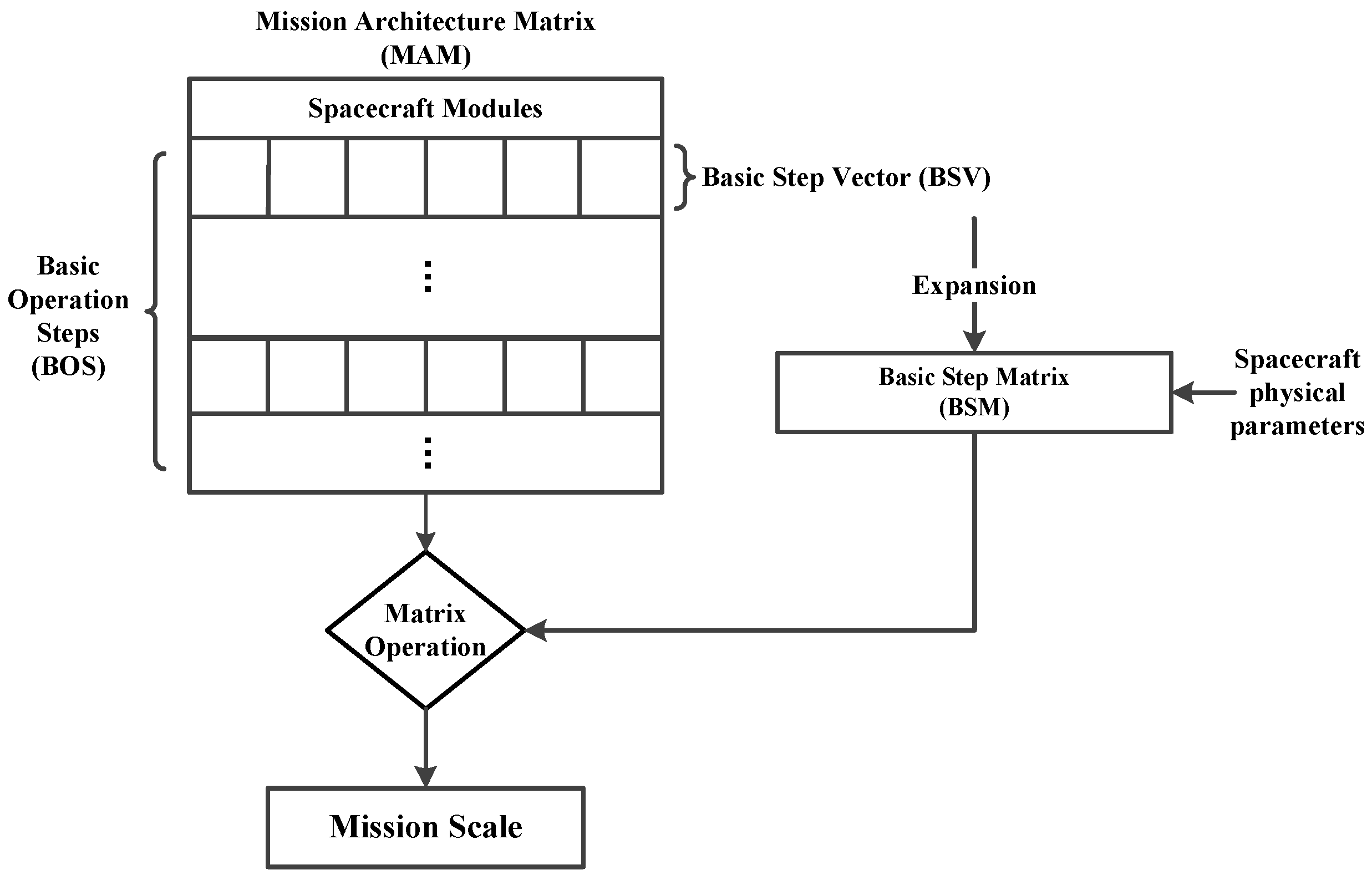
Figure 1.
Schematic diagram of the MAM method.
Figure 1.
Schematic diagram of the MAM method.
Figure 2.
Mission profile for impulse maneuver transfers (Hohmann transfers) in heliocentric coordinate system.
Figure 2.
Mission profile for impulse maneuver transfers (Hohmann transfers) in heliocentric coordinate system.
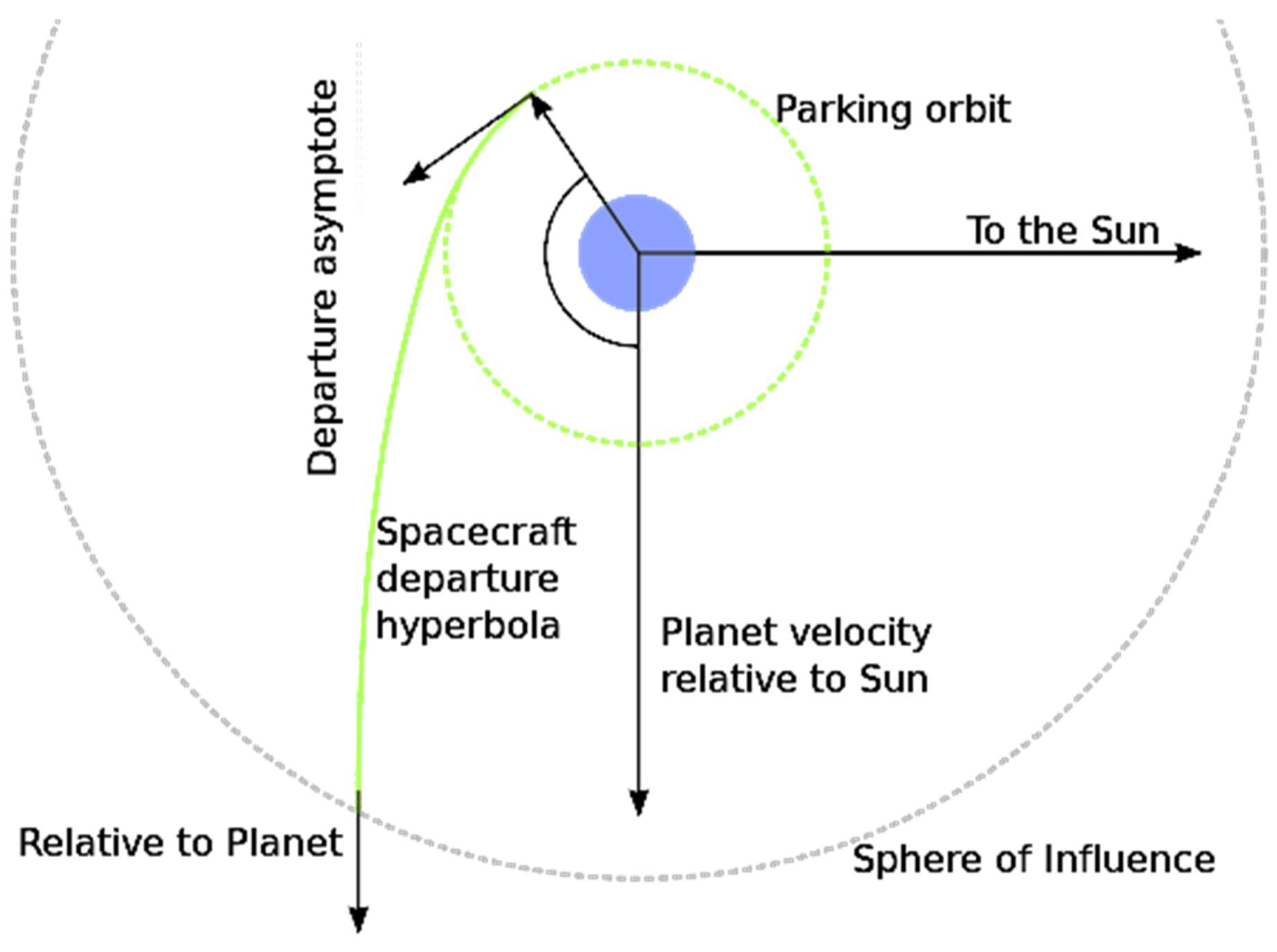
Figure 3.
Departure of a spacecraft on a mission from an inner planet to an outer planet.
Figure 3.
Departure of a spacecraft on a mission from an inner planet to an outer planet.
Figure 4.
Mission profile for impulse maneuver transfers (Lambert transfers) in heliocentric coordinate system.
Figure 4.
Mission profile for impulse maneuver transfers (Lambert transfers) in heliocentric coordinate system.
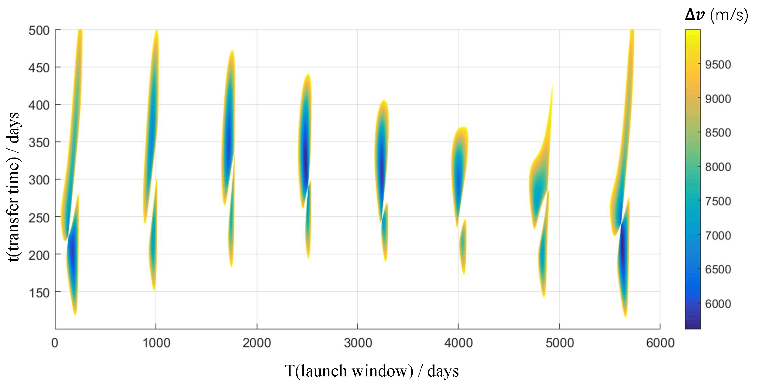
Figure 5.
Total for Earth-to-Mars Lambert transfer from 2035 to 2050. The horizontal axis is launch windows (in days after 1 January 2035), and the vertical axis is transfer time (in days).
Figure 5.
Total for Earth-to-Mars Lambert transfer from 2035 to 2050. The horizontal axis is launch windows (in days after 1 January 2035), and the vertical axis is transfer time (in days).
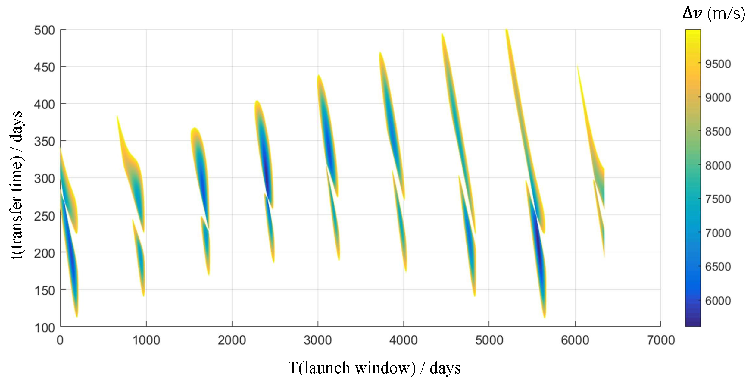
Figure 6.
Total for Mars-to-Earth Lambert transfer from 2035 to 2050. The horizontal axis is launch windows (in days after 1 January 2035), and the vertical axis is transfer time (in days).
Figure 6.
Total for Mars-to-Earth Lambert transfer from 2035 to 2050. The horizontal axis is launch windows (in days after 1 January 2035), and the vertical axis is transfer time (in days).
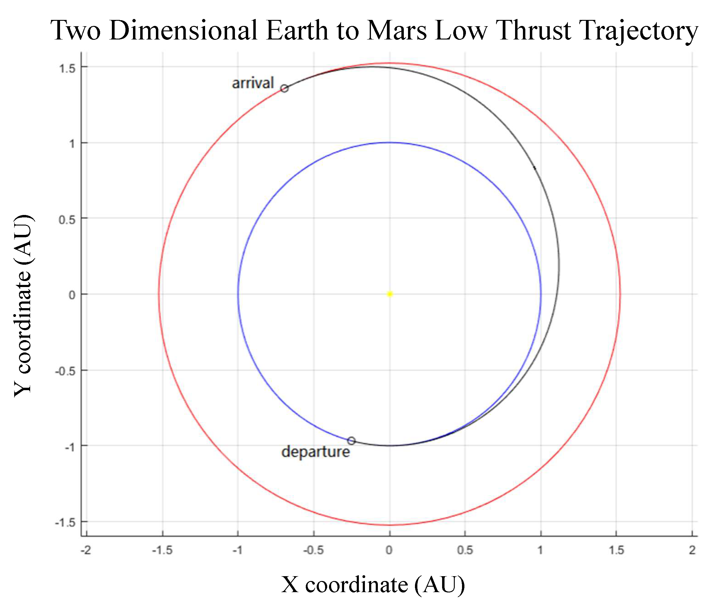
Figure 7.
Heliocentric trajectories Earth to Mars (units in meters). This is one of the optimal mission profiles based on low-thrust orbital transfers using electric propulsion engines. The sun is at centre of the coordinate, the blue orbit is the Earth orbit, and the orange orbit is the Mars orbit. The black curve is the trajectory of the transfer.
Figure 8.
Steering angle (deg) for the mission profile in
Figure 7. The horizontal axis is transfer time (in days).
Figure 8.
Steering angle (deg) for the mission profile in
Figure 7. The horizontal axis is transfer time (in days).
Figure 9.
Four mission nodes and seven mission phases in manned Mars mission.
Figure 9.
Four mission nodes and seven mission phases in manned Mars mission.
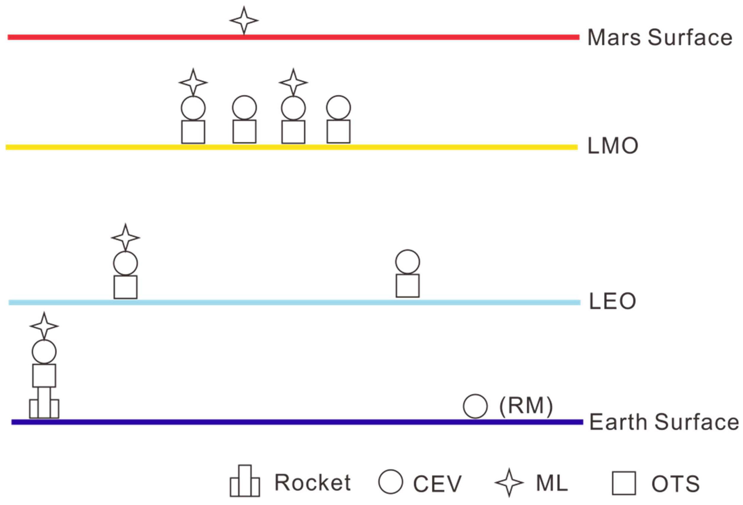
Figure 10.
Schematic of Architecture-1.
Figure 10.
Schematic of Architecture-1.
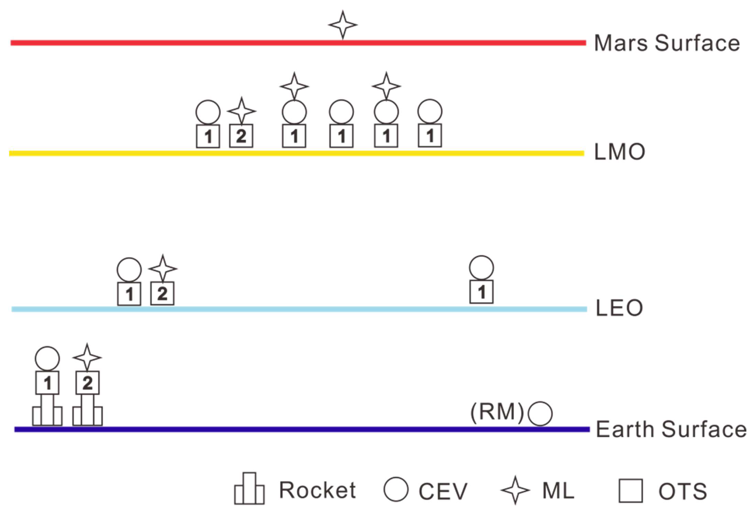
Figure 11.
Schematic of Architecture-2.
Figure 11.
Schematic of Architecture-2.
Figure 12.
Schematic of Architecture-3.
Figure 12.
Schematic of Architecture-3.
Figure 13.
Schematic of Architecture-4.
Figure 13.
Schematic of Architecture-4.
Figure 14.
Schematic of Architecture-9.
Figure 14.
Schematic of Architecture-9.
Figure 15.
Schematic of Architecture-10.
Figure 15.
Schematic of Architecture-10.
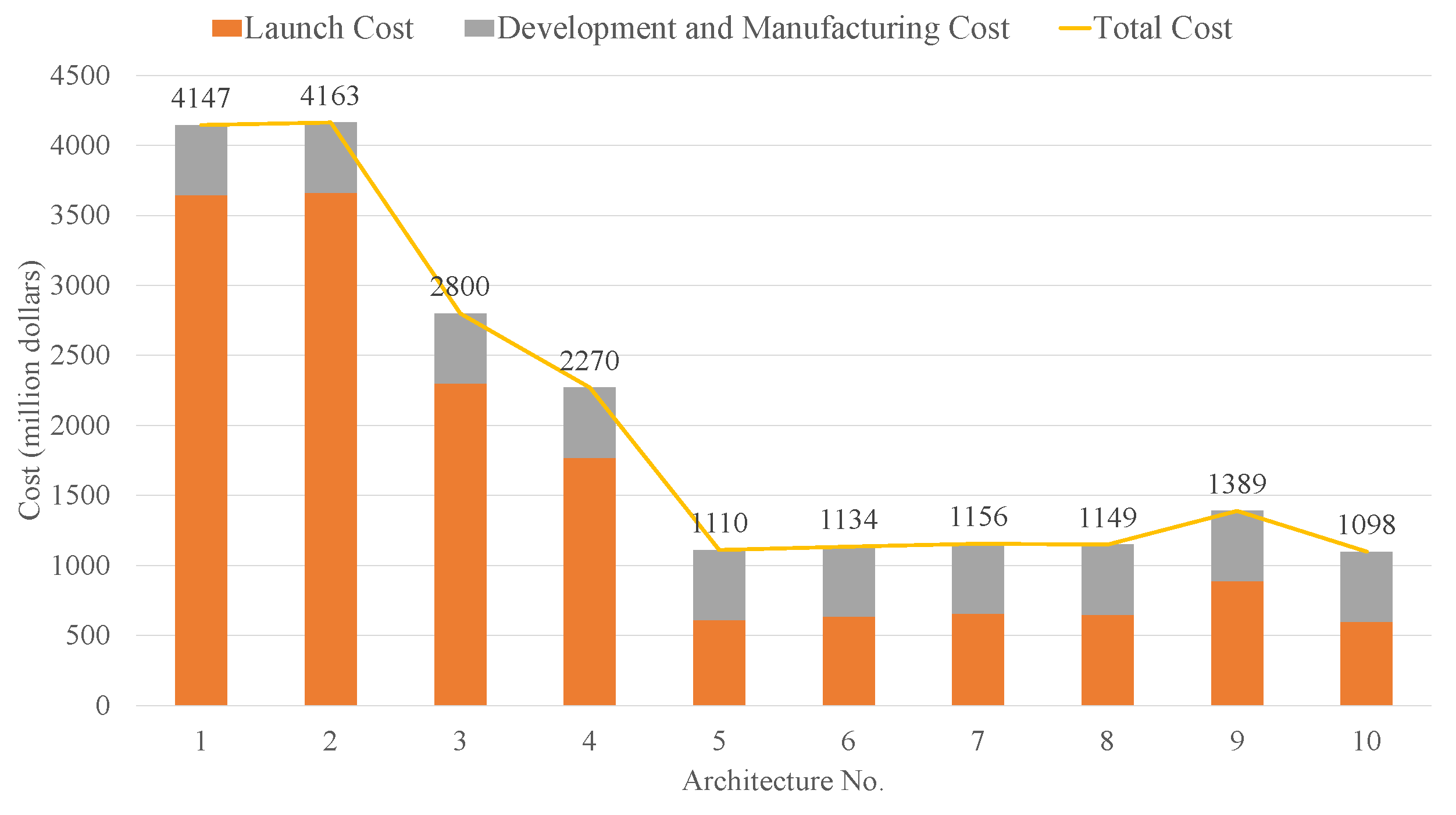
Figure 16.
Total cost of 10 different architecture.
Figure 16.
Total cost of 10 different architecture.
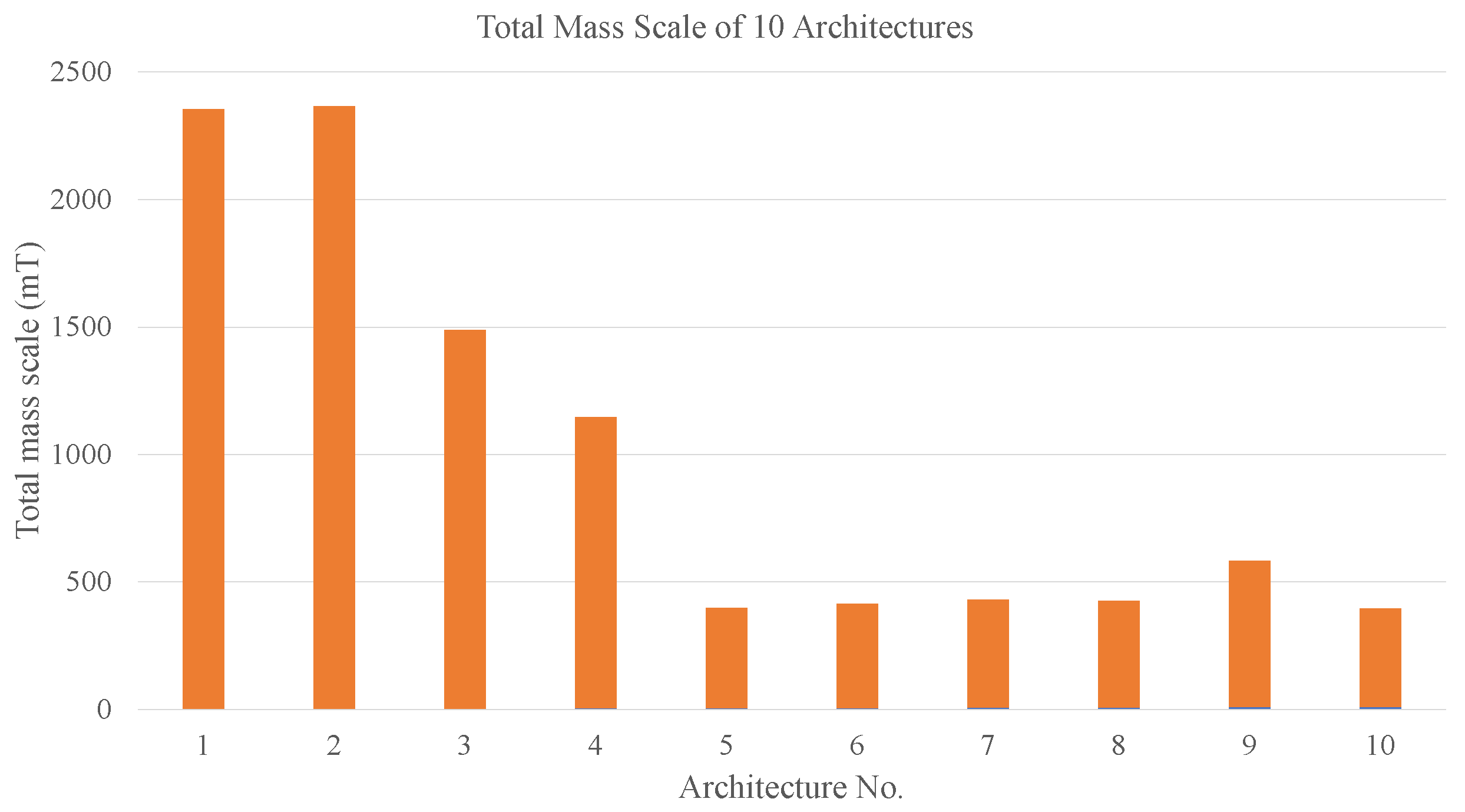
Figure 17.
Total mass scale of 10 different architecture.
Figure 17.
Total mass scale of 10 different architecture.
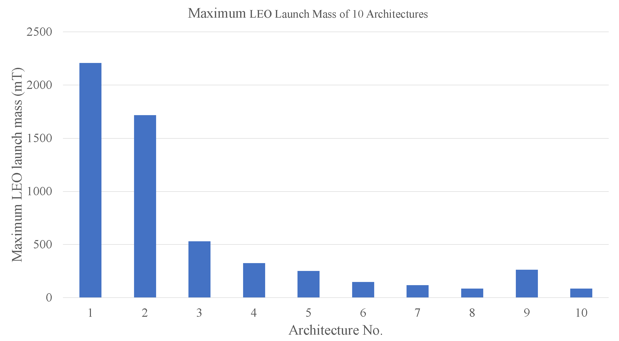
Figure 18.
Maximum LEO launch mass of 10 different architecture.
Figure 18.
Maximum LEO launch mass of 10 different architecture.
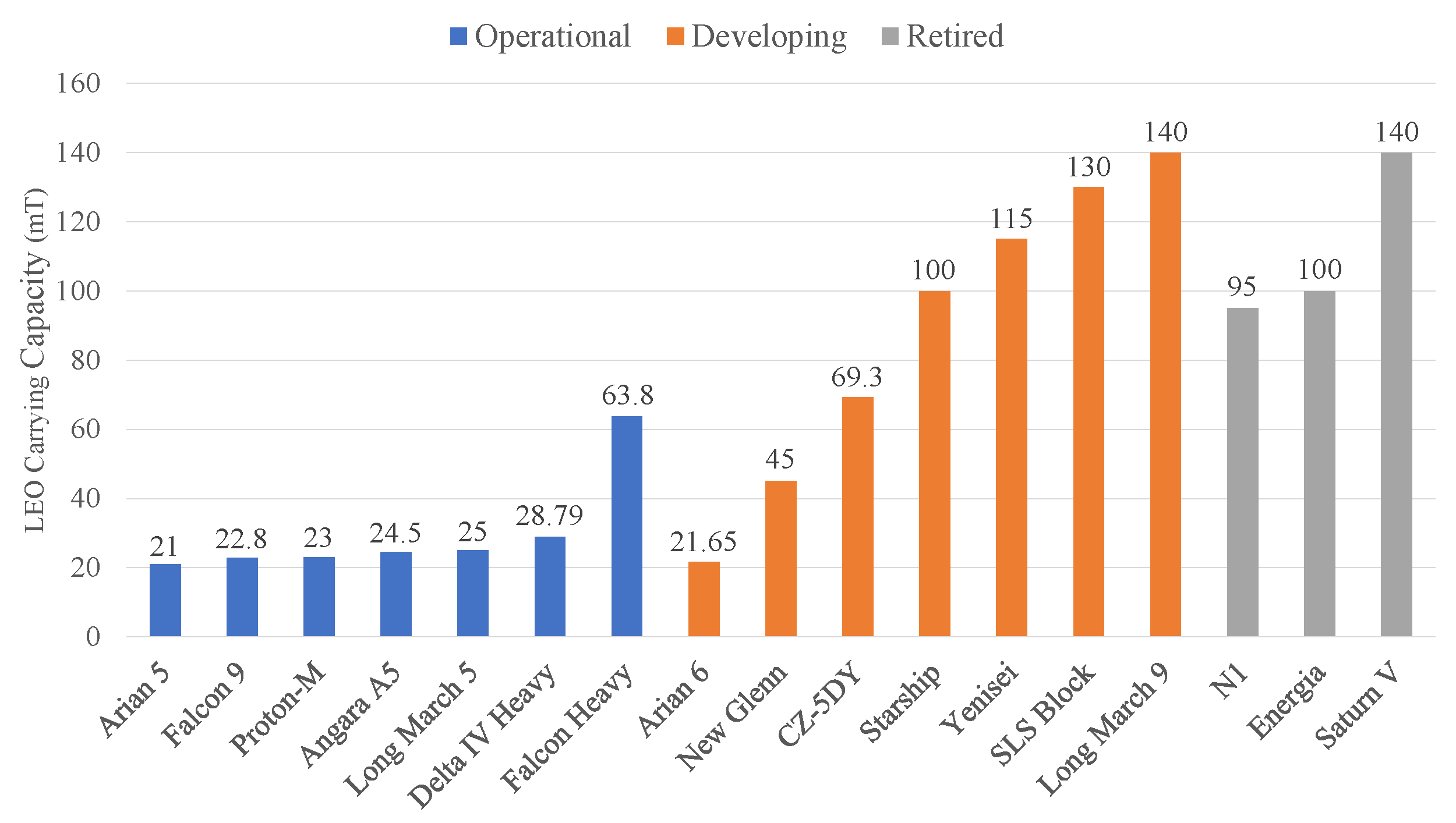
Figure 19.
Current LEO carrying capacity of large and heavy-lift launch vehicles.
Figure 19.
Current LEO carrying capacity of large and heavy-lift launch vehicles.
Figure 20.
Comparison of the maximum LEO launch mass of 10 architectures with the LEO carrying capacity of selected launch vehicles.
Figure 20.
Comparison of the maximum LEO launch mass of 10 architectures with the LEO carrying capacity of selected launch vehicles.
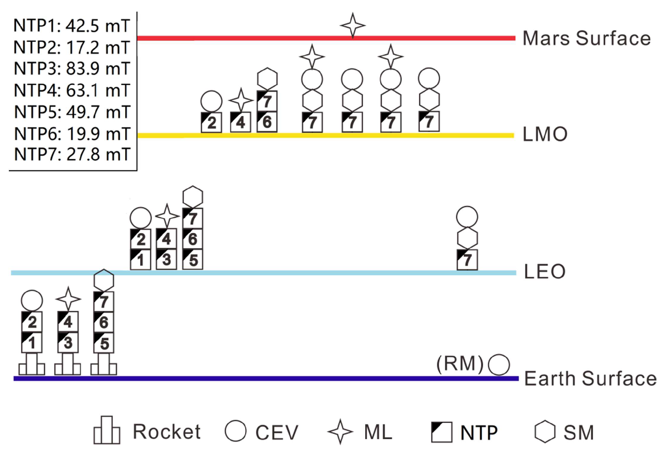
Figure 21.
Mission profile of Architecture-8.
Figure 21.
Mission profile of Architecture-8.
Table 1.
Parameters ofthe Hohmann transfer for Earth–Mars and Mars–Earth. The velocity increments in this table are all actual departure from LEO/LMO.
Table 1.
Parameters ofthe Hohmann transfer for Earth–Mars and Mars–Earth. The velocity increments in this table are all actual departure from LEO/LMO.
| Mission Duration (Days) | Velocity Increments (km/s) |
|---|
| Total Duration | Earth-Mars | Mars Residence | Mars-Earth | Total Impulse | | | | |
|---|
| 972.1 | 258.9 | 454.4 | 258.9 | 7.8 | 3.6 | 2.1 | 2.1 | 11.5 |
Table 2.
Optimal mission profiles for manned Mars mission using chemical engines. Time of expedition: <1000 days. The launch window is 2035–2050. The velocity increments in this table are all actual departure from LEO/LMO.
Table 2.
Optimal mission profiles for manned Mars mission using chemical engines. Time of expedition: <1000 days. The launch window is 2035–2050. The velocity increments in this table are all actual departure from LEO/LMO.
Launch
Date
(dd.mm.yy) | Mission Duration (Days) | Velocity Increments (km/s) |
|---|
Total
Duration | Earth–Mars | Mars Residence | Mars–Earth | Total
Impulse | | | | |
|---|
| 09.07.2035 | 928.2 | 184.3 | 544.1 | 199.7 | 8.4 | 3.6 | 2.1 | 2.7 | 11.9 |
| 05.09.2037 | 982.9 | 227.6 | 453.1 | 302.2 | 8.4 | 4.0 | 2.0 | 2.3 | 11.5 |
| 14.10.2039 | 974.0 | 224.2 | 433.1 | 316.8 | 8.6 | 4.0 | 2.4 | 2.2 | 11.6 |
| 24.11.2041 | 977.7 | 208.7 | 431.2 | 337.9 | 9.2 | 4.2 | 3.0 | 2.0 | 11.6 |
| 03.01.2044 | 987.3 | 185.6 | 481.2 | 320.6 | 9.9 | 4.2 | 3.7 | 2.0 | 12.1 |
| 12.02.2046 | 978.5 | 155.8 | 546.7 | 276.1 | 10.0 | 4.3 | 3.8 | 1.9 | 12.0 |
| 05.04.2048 | 988.4 | 151.1 | 598.4 | 238.9 | 8.7 | 3.9 | 3.0 | 1.9 | 11.6 |
| 06.06.2050 | 977.4 | 161.8 | 589.8 | 225.8 | 8.5 | 3.6 | 2.5 | 2.4 | 11.6 |
Table 3.
Parameters for one optimal mission profile for manned Mars mission using electric propulsion engines. Time of expedition: <1000 days. The launch window is 2035–2050.
Table 3.
Parameters for one optimal mission profile for manned Mars mission using electric propulsion engines. Time of expedition: <1000 days. The launch window is 2035–2050.
| | Transfer Duration | Start Time | End Time | Total 1 |
|---|
| Earth-to-Mars | 300 days | 7 June 2037 | 3 April 2038 | 6.1 km/s |
| Mars-to-Earth | 300 days | 11 August 2039 | 6 June 2040 | 9.4 km/s |
Table 4.
The basic parameters of all considered modules.
Table 4.
The basic parameters of all considered modules.
| Modules | CEV | ML | OTS | NTP | NEP | SM |
|---|
| Dry mass (tons) | 60 | 85 | - | 1 | 60 | 20 |
| Dry mass ratio | - | - | 0.1 | - | - | |
| Specific impulse | - | - | 440 s | 900 s | 6000 s | - |
Table 5.
Mission architecture matrix of Architecture-1.
Table 5.
Mission architecture matrix of Architecture-1.
| (BOS) | No. | RVD 1 | CEV | ML | OTS | IMV 1 | (m/s) |
|---|
| Launching to LEO | 1 | 0 | 1 | 1 | 1 | 0 | 0 |
| LEO accelerating (leaving) (dv1) | 2 | 0 | 1 | 1 | 2 | 3 | 4011 |
| Orbit Correction (OCC1) 2 | 3 | 0 | 1 | 1 | 2 | 3 | 302 |
| LMO accelerating (reaching) (dv2) | 4 | 0 | 1 | 1 | 2 | 3 | 2020 |
| LMO stay | 5 | 0 | 1 | 1 | 1 | 0 | 0 |
| Landing/Launching on Mars | 6 | 0 | 0 | 1 | 0 | 0 | 0 |
| LMO docking 3 | 7 | 1 | 1 | 1 | 2 | 3 | 0.01 |
| LMO accelerating (leaving) (dv3) | 8 | 0 | 1 | 0 | 2 | 3 | 2334 |
| Orbit Correction (OCC2) | 9 | 0 | 1 | 0 | 2 | 3 | 117 |
Table 6.
Mass scale of Architecture-1.
Table 6.
Mass scale of Architecture-1.
| Module | CEV | ML | OTS | Total | Max Mass |
|---|
| Original mass () | 60,000 | 85,000 | 2,207,831 | 2,352,831 | 2,207,831 |
| Final mass () | 60,000 | 85,000 | 220,783 | 365,783 | - |
Table 7.
Mission architecture matrix of Architecture-2.
Table 7.
Mission architecture matrix of Architecture-2.
| (BOS) | No. | RVD | CEV | ML | OTS1 | OTS2 | IMV | (m/s) |
|---|
| LEO | 1 | 0 | 1 | 1 | 1 | 1 | 0 | 0 |
| dv1 (CEV) | 2 | 0 | 1 | 0 | 2 | 0 | 3 | 4011 |
| dv1 (ML) | 3 | 0 | 0 | 1 | 0 | 2 | 4 | 4011 |
| OCC1 (CEV) | 4 | 0 | 1 | 0 | 2 | 0 | 3 | 302 |
| OCC1 (ML) | 5 | 0 | 0 | 1 | 0 | 2 | 4 | 302 |
| dv2 (CEV) | 6 | 0 | 1 | 0 | 2 | 0 | 3 | 2020 |
| dv2 (ML) | 7 | 0 | 0 | 1 | 0 | 2 | 4 | 2020 |
| LMO stay | 8 | 0 | 1 | 1 | 1 | 1 | 0 | 0.01 |
| Landing | 9 | 0 | 0 | 1 | 0 | 0 | 0 | 0 |
| LMO docking | 10 | 1 | 1 | 1 | 2 | 0 | 3 | 0.01 |
| dv3 | 11 | 0 | 1 | 0 | 2 | 0 | 3 | 2334 |
| OCC2 | 12 | 0 | 1 | 0 | 2 | 0 | 3 | 117 |
Table 8.
Mass scale of Architecture-2.
Table 8.
Mass scale of Architecture-2.
| Module | CEV | ML | OTS1 | OTS2 | Total | Max Mass |
|---|
| () | 60,000 | 85,000 | 1,715,989 | 502,438 | 2,363,427 | 1,715,989 |
| () | 60,000 | 85,000 | 171,599 | 50,244 | 366,843 | - |
Table 9.
Mission architecture matrix of Architecture-3.
Table 9.
Mission architecture matrix of Architecture-3.
| (BOS) | No. | RVD | CEV | ML | SM | OTS1 | OTS2 | OTS3 | OTS4 | IMV | (m/s) |
|---|
| LEO | 1 | 0 | 1 | 1 | 1 | 1 | 1 | 1 | 1 | 0 | 0 |
| dv1 (CEV) | 2 | 0 | 1 | 0 | 0 | 2 | 0 | 0 | 0 | 4 | 4011 |
| dv1 (ML) | 3 | 0 | 0 | 1 | 0 | 0 | 2 | 0 | 0 | 5 | 4011 |
| dv1(SM) | 4 | 0 | 0 | 0 | 1 | 0 | 0 | 2 | 1 | 6 | 4011 |
| OCC1 (CEV) | 5 | 0 | 1 | 0 | 0 | 2 | 0 | 0 | 0 | 4 | 302 |
| OCC1 (ML) | 6 | 0 | 0 | 1 | 0 | 0 | 2 | 0 | 0 | 5 | 302 |
| OCC1 (SM) | 7 | 0 | 0 | 0 | 1 | 0 | 0 | 2 | 1 | 6 | 302 |
| dv2 (CEV) | 8 | 0 | 1 | 0 | 0 | 2 | 0 | 0 | 0 | 4 | 2020 |
| dv2 (ML) | 9 | 0 | 0 | 1 | 0 | 0 | 2 | 0 | 0 | 5 | 2020 |
| dv2 (SM) | 10 | 0 | 0 | 0 | 1 | 0 | 0 | 2 | 1 | 6 | 2020 |
| LMO stay | 11 | 0 | 1 | 1 | 1 | 1 | 1 | 1 | 1 | 0 | 0 |
| Landing | 12 | 0 | 0 | 1 | 0 | 0 | 0 | 0 | 0 | 0 | 0 |
| LMO docking | 13 | 1 | 1 | 1 | 1 | 0 | 0 | 0 | 2 | 7 | 0.01 |
| dv3 | 14 | 0 | 1 | 0 | 1 | 0 | 0 | 0 | 2 | 7 | 2334 |
| OCC2 | 15 | 0 | 1 | 0 | 1 | 0 | 0 | 0 | 2 | 7 | 117 |
Table 10.
Mass scale of Architecture-3.
Table 10.
Mass scale of Architecture-3.
| Module | kg | (kg) | Module | kg | (kg) |
|---|
| CEV | 40,000 | 40,000 | OTS3 | 530,409 | 53,041 |
| ML | 85,000 | 85,000 | OTS4 | 69,732 | 6973 |
| SM | 20,000 | 20,000 | Total | 1,484,021 | 278,902 |
| OTS1 | 236,442 | 23,644 | Max mass | 530,409 | - |
| OTS2 | 502,438 | 50,244 | | | |
Table 11.
Mission architecture matrix of Architecture-4.
Table 11.
Mission architecture matrix of Architecture-4.
| (BOS) | No. | RVD | CEV | ML | SM | OTS1 | OTS2 | OTS3 | OTS4 | OTS5 | OTS6 | OTS7 | IMV | (m/s) |
|---|
| LEO | 1 | 0 | 1 | 1 | 1 | 1 | 1 | 1 | 1 | 1 | 1 | 1 | 0 | 0 |
| dv1 (CEV) | 2 | 0 | 1 | 0 | 0 | 2 | 1 | 0 | 0 | 0 | 0 | 0 | 4 | 4011 |
| dv1 (ML) | 3 | 0 | 0 | 1 | 0 | 0 | 0 | 2 | 1 | 0 | 0 | 0 | 6 | 4011 |
| dv1(SM) | 4 | 0 | 0 | 0 | 1 | 0 | 0 | 0 | 0 | 2 | 1 | 1 | 8 | 4011 |
| OCC1 (CEV) | 5 | 0 | 1 | 0 | 0 | 0 | 2 | 0 | 0 | 0 | 0 | 0 | 5 | 302 |
| OCC1 (ML) | 6 | 0 | 0 | 1 | 0 | 0 | 0 | 0 | 2 | 0 | 0 | 0 | 7 | 302 |
| OCC1 (SM) | 7 | 0 | 0 | 0 | 1 | 0 | 0 | 2 | 1 | 0 | 2 | 1 | 9 | 302 |
| dv2 (CEV) | 8 | 0 | 1 | 0 | 0 | 0 | 2 | 0 | 0 | 0 | 0 | 0 | 5 | 2020 |
| dv2 (ML) | 9 | 0 | 0 | 1 | 0 | 0 | 0 | 0 | 2 | 0 | 0 | 0 | 7 | 2020 |
| dv2 (SM) | 10 | 0 | 0 | 0 | 1 | 0 | 0 | 0 | 0 | 0 | 2 | 1 | 9 | 2020 |
| LMO stay | 11 | 0 | 1 | 1 | 1 | 0 | 1 | 0 | 1 | 0 | 1 | 1 | 0 | 0 |
| Landing | 12 | 0 | 0 | 1 | 0 | 0 | 0 | 0 | 0 | 0 | 0 | 0 | 0 | 0 |
| LMO docking | 13 | 1 | 1 | 1 | 1 | 0 | 0 | 0 | 0 | 0 | 0 | 2 | 10 | 0.01 |
| dv3 | 14 | 0 | 1 | 0 | 1 | 0 | 0 | 0 | 0 | 0 | 0 | 2 | 10 | 2334 |
| OCC2 | 15 | 0 | 1 | 0 | 1 | 0 | 0 | 0 | 0 | 0 | 0 | 2 | 10 | 117 |
Table 12.
Mass scale of Architecture-4.
Table 12.
Mass scale of Architecture-4.
| Module | (kg) | (kg) | Module | (kg) | (kg) |
|---|
| CEV | 40,000 | 40,000 | OTS4 | 73,181 | 7318 |
| ML | 85,000 | 85,000 | OTS5 | 289,960 | 28,996 |
| SM | 20,000 | 20,000 | OTS6 | 65,238 | 6524 |
| OTS1 | 153,064 | 15,306 | OTS7 | 55,774 | 5577 |
| OTS2 | 34,438 | 3444 | Total | 1,141,917 | 244,692 |
| OTS3 | 325,261 | 32,526 | Max mass | 325,261 | - |
Table 13.
Mass scale of Architecture-5.
Table 13.
Mass scale of Architecture-5.
| Module | CEV | ML | NTP | Total | Max Mass |
|---|
| Original mass () | 60,000 | 85,000 | 250,788 | 393,788 | 250,788 |
| Final mass () | 60,000 | 85,000 | 26,879 | 171,879 | - |
Table 14.
Mass scale of Architecture-6.
Table 14.
Mass scale of Architecture-6.
| Module | CEV | ML | NTP1 | NTP2 | Total | Max Mass |
|---|
| () | 60,000 | 85,000 | 147,139 | 116,953 | 409,092 | 147,139 |
| () | 60,000 | 85,000 | 16,514 | 13,495 | 175,009 | - |
Table 15.
Mass scale of Architecture-7.
Table 15.
Mass scale of Architecture-7.
| Module | (kg) | (kg) | Module | (kg) | (kg) |
|---|
| CEV | 40,000 | 40,000 | NTP3 | 69,681 | 8768 |
| ML | 85,000 | 85,000 | NTP4 | 31,223 | 4922 |
| SM | 20,000 | 20,000 | Total | 422,995 | 179,999 |
| NTP1 | 60,137 | 7814 | Max mass | 116,953 | - |
| NTP2 | 116,953 | 13,495 | | | |
Table 16.
Mass scale of Architecture-8.
Table 16.
Mass scale of Architecture-8.
| Module | (kg) | (kg) | Module | (kg) | (kg) |
|---|
| CEV | 40,000 | 40,000 | NEP4 | 63,108 | 6311 |
| ML | 85,000 | 85,000 | NTP5 | 49,695 | 6770 |
| SM | 20,000 | 20,000 | NTP6 | 19,946 | 3795 |
| NTP1 | 42,486 | 6049 | NTP7 | 27,835 | 4584 |
| NTP2 | 17,234 | 3523 | Total | 418,905 | 184,990 |
| NTP3 | 83,893 | 10,189 | Max mass | 85,000 | - |
Table 17.
Mission architecture matrix of Architecture-9.
Table 17.
Mission architecture matrix of Architecture-9.
| (BOS) | No. | RVD | CEV | ML | NEP | NTP | IMV | (m/s) |
|---|
| Launching to LEO | 1 | 0 | 1 | 1 | 1 | 1 | 0 | 0 |
| LEO escape | 2 | 0 | 1 | 1 | 1 | 2 | 4 | 3175 |
| LEO-LMO transfer | 3 | 0 | 1 | 1 | 2 | 1 | 3 | 6050 |
| LMO entry | 4 | 0 | 1 | 1 | 1 | 2 | 4 | 1449 |
| LMO stay | 5 | 0 | 1 | 1 | 1 | 1 | 0 | 0 |
| Landing | 6 | 0 | 0 | 1 | 0 | 0 | 0 | 0 |
| LMO docking | 7 | 1 | 1 | 1 | 2 | 1 | 3 | 0.01 |
| LMO escape | 8 | 0 | 1 | 0 | 1 | 2 | 4 | 1449 |
| LMO-Earth transfer | 9 | 0 | 1 | 0 | 2 | 1 | 3 | 5491 |
Table 18.
Mass scale of Architecture-9.
Table 18.
Mass scale of Architecture-9.
| Module | CEV | ML | NEP | NTP | Total | Max Mass |
|---|
| () | 60,000 | 85,000 | 166,648 | 261,983 | 573,631 | 261,983 |
| () | 60,000 | 85,000 | 60,000 | 26,198 | 231,198 | - |
Table 19.
Mission architecture matrix of Architecture-10.
Table 19.
Mission architecture matrix of Architecture-10.
| (BOS) | No. | RVD | CEV | ML | SM | NEP | NTP1 | NTP2 | NTP3 | NTP4 | NTP5 | IMV | (m/s) |
|---|
| LEO Launch | 1 | 0 | 1 | 1 | 1 | 1 | 1 | 1 | 1 | 1 | 1 | 0 | 0 |
| LEO escape (M) | 2 | 0 | 0 | 1 | 0 | 2 | 0 | 0 | 0 | 0 | 0 | 4 | 3175 |
| E-to-M (M) | 3 | 0 | 0 | 1 | 0 | 2 | 0 | 0 | 0 | 0 | 0 | 4 | 6050 |
| LMO entry (M) | 4 | 0 | 0 | 1 | 0 | 2 | 0 | 0 | 0 | 0 | 0 | 4 | 1449 |
| dv1 (C) | 5 | 0 | 1 | 0 | 0 | 0 | 2 | 1 | 0 | 0 | 0 | 5 | 4011 |
| OCC1 (C) | 6 | 0 | 1 | 0 | 0 | 0 | 0 | 2 | 0 | 0 | 0 | 6 | 302 |
| dv2 (C) | 7 | 0 | 1 | 0 | 0 | 0 | 0 | 2 | 0 | 0 | 0 | 6 | 2020 |
| dv1 (S) | 8 | 0 | 1 | 0 | 0 | 0 | 0 | 0 | 2 | 1 | 1 | 7 | 4011 |
| OCC1 (S) | 9 | 0 | 1 | 0 | 0 | 0 | 0 | 0 | 0 | 2 | 1 | 8 | 302 |
| dv2 (S) | 10 | 0 | 1 | 0 | 0 | 0 | 0 | 0 | 0 | 2 | 1 | 8 | 2020 |
| LMO stay | 11 | 0 | 1 | 1 | 1 | 1 | 0 | 1 | 0 | 1 | 1 | 0 | 0 |
| Landing | 12 | 0 | 0 | 1 | 0 | 0 | 0 | 0 | 0 | 0 | 0 | 0 | 0 |
| LMO docking | 13 | 1 | 1 | 1 | 1 | 1 | 0 | 0 | 0 | 0 | 2 | 9 | 0.01 |
| dv3 (C) | 14 | 0 | 1 | 0 | 1 | 0 | 0 | 0 | 0 | 0 | 2 | 9 | 2334 |
| OCC2 (C) | 15 | 0 | 1 | 0 | 1 | 0 | 0 | 0 | 0 | 0 | 2 | 9 | 117 |
Table 20.
Mass scale of Architecture-10.
Table 20.
Mass scale of Architecture-10.
| Module | (kg) | (kg) | Module | (kg) | (kg) |
|---|
| CEV | 40,000 | 40,000 | NTP3 | 49,695 | 6770 |
| ML | 85,000 | 85,000 | NTP4 | 19,946 | 3795 |
| SM | 20,000 | 20,000 | NTP5 | 27,835 | 4584 |
| NEP | 83,631 | 60,000 | Total | 385,827 | 229,721 |
| NTP1 | 42,486 | 6049 | Max mass | 85,000 | - |
| NTP2 | 17,234 | 3523 | | | |
Table 21.
LEO Launch schedule.
Table 21.
LEO Launch schedule.
| LEO Launch No. | Module (s) | LEO Capacity Requirement (tons) |
|---|
| 1 | ML | 85.0 |
| 2 | NTP3 | 83.9 |
| 3 | NTP1 + NTP2 | 59.7 |
| 4 | NTP4 | 63.1 |
| 5 | NTP5 + NTP6 | 69.6 |
| 6 | NTP7 + SM | 47.8 |
| Total | All modules | 418.9 |
Table 22.
Detailed process of manned Mars exploration mission.
Table 22.
Detailed process of manned Mars exploration mission.
| Time | Event |
|---|
| Before 5 September 2037 | All modules are launched to LEO and docked as 3 transfer combinations. |
| 5 September 2037 | 3 combinations start Earth-to-Mars transfer, and NTP-1, 3, and 5 are abandoned after the first maneuver. |
| 21 April 2038 | 3 combinations arrive at LMO, and NTP-2, 4, and 6 are abandoned after the second maneuver. All modules start preparations for Mars landing. |
| 21 April 2038–18 July 2039 | CEV, ML, SM, and NTP-7 are docked together. The astronauts enter ML and then land on Mars, while the combination of CEV+SM+NTP-7 stays at LMO. After the landing mission, the astronauts go back to LMO using the upper stage and docking with CEV. Finally, the crew enters CEV and the upper stage is abandoned. |
| 18 July 2039 | The combination of CEV+SM+NTP-7 starts Mars-to-Earth transfer. |
| 15 May 2040 | The combination of CEV+SM+NTP-7 arrives at Earth. The astronauts enter the return cabin of CEV, re-enter the atmosphere and return to the ground. |
| Total mission time | 983 days |


