Article

Dynamics, Deployment and Retrieval Strategy for Satellite-Sail Transverse Formation with Model Inaccuracy

School of Astronautics, Beihang University, Beijing 100191, China
*
Author to whom correspondence should be addressed.
Aerospace 2022, 9(10), 602; https://doi.org/10.3390/aerospace9100602
Submission received: 31 August 2022 / Revised: 30 September 2022 / Accepted: 3 October 2022 / Published: 14 October 2022

Abstract

:
One of the important applications of the space tethered system is formation flying. To satisfy the requirement for interferometry of ground targets by remote-sensing satellites, a new type of tethered solar sail spacecraft has been proposed in recent research. The replacement of subsatellites of conventional tethered satellite systems with solar sail spacecraft allows for a special formation configuration in which the main satellite is in sun-synchronous orbit and the subsolar sail is in displaced orbit. If the solar sail is at the appropriate attitude, the main satellite and the solar sail spacecraft connected by metal tethers could move side by side, hence this formation system is called transverse formation. The relative baseline of this transverse formation system is perpendicular to the ground trajectory of the satellite, effectively solving the problem that the relative baseline of conventional orbital formations varies in a trigonometric cycle. Researchers on the past ignored the mass and elasticity of the tether, and considered the tether just a constraint in the model system. Since the solar sail is generally quite light compared to the other components of the system, the model inaccuracy caused by ignoring the mass of the tether on the dynamic model and control is extremely obvious. This paper investigates the relative dynamics and control of a proposed system during the deployment process with the mass of the tether. Two precise models of satellite-sail systems are established. One is based on the dumbbell model with the mass tether for the tethered satellite system, and the other is on the basis of the beads model of a tethered satellite system. The rigid one is for control design and the flexible one is for dynamic simulation. It is concluded that the length of the tether and attitude angle of the transverse formation configuration can be decoupled and controlled separately. On the basis of the models, a length rate and LQR control law is developed and the control of the deployment and retrieval process of the tethered solar sail system is investigated. Numerical simulations are performed to verify the accuracy of the conclusions.

1. Introduction

Since satellite formation flying was proposed in the 1990s, it has become a research hotspot of space technology in the 21st century [1]. Satellite formation flying plays a key role in satellite remote sensing, electronic reconnaissance, deep-space exploration, and other space missions [2]. Remote-sensing satellites image ground targets through Earth observation equipment with important applications in optical reconnaissance, agricultural production, engineering surveying, urban planning, etc. Satellite formation flying is a large-scale system combining two or more small satellites flying to maintain the formation of a specific spatial configuration. The satellites involved in the formation jointly undertake missions of collecting and processing space signals and carrying payloads through the communication link for information transfer to jointly satisfy the needs of the mission.
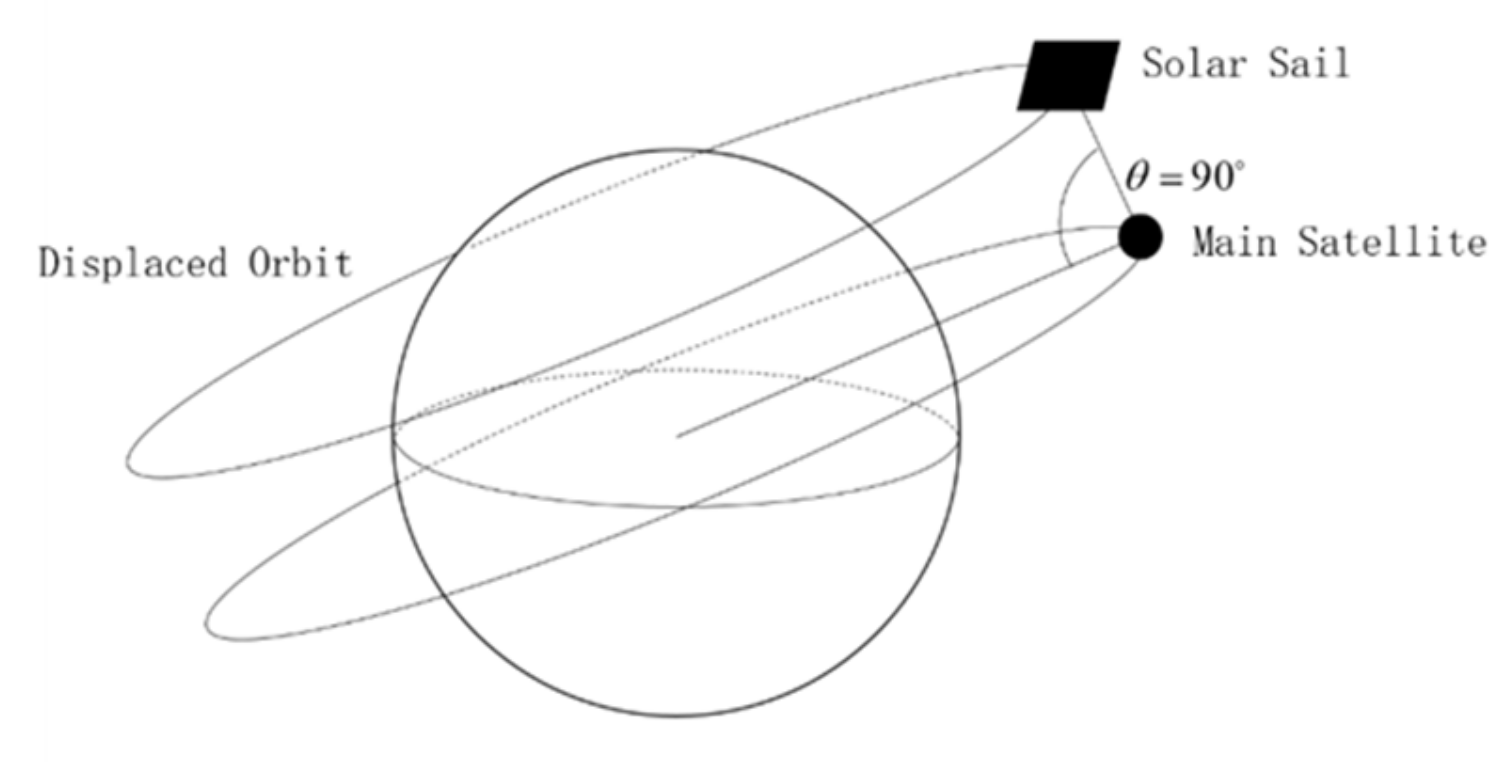
A general two-body satellite formation consisting of a main spacecraft and a subspacecraft, which normally describes relative motion using the Clohessy–Wiltshire (C-W) equation, has been sufficiently investigated in previous studies [3,4,5,6]. However, the relative baseline of such fly-around formations is a trigonometric periodic change, which is not conductive to the requirements of Earth observation and other formation-flying applications. To overcome the complication, a new type of two-body satellite formation flying has been proposed in recent studies. Solar sails can move in special displaced orbits because of the continuous solar radiation pressure. The characteristic of solar sail spacecraft can be used to form a special spatial configuration in which the main satellite is in a sun-synchronous orbit (SSO) and the subsolar sail in a displaced orbit parallel to the orbital plane of the main satellite. Pan et al. investigated a new solar sail system consisting of a sun-synchronous orbiting satellite and a solar sail in a parallel displaced orbit [7]. As shown in Figure 1, the main satellite and the solar sail can move side by side if the solar sail is at the appropriate attitude, hence the name of this formation system is transverse formation. The relative baseline of the transverse formation system is perpendicular to the track of the subsatellite point, effectively solving the problem of the trigonometric periodic change of the relative baseline of the classical fly-around formation.
However, since solar sails are extremely light in general, a single solar sail is not capable of carrying the required payload unless a huge sail is used, posing an enormous challenge to both solar sail fabrication and deployment. This problem was further discussed in [7], where the main satellite was connected to the solar sail by a metal tether, following the structure of the space tethered satellite. The system could be controlled. The primary payload required for the mission can be carried on the main satellite, and the electrical energy required for the cameras on the sail is transmitted via a conductive tether. The tethered satellite system is used to maintain the spacecraft in formation flying at a constant distance, with the tension of the tether ensuring the stability of the configuration. A tethered satellite with no additional thrust has merely a single control force along the longitudinal axis of the tether, which is the tension of the tether. The attitude angle of the tethered satellite is not effectively controlled, such that the tethered satellite is a typical underactuated system. With replacement of the subsatellite of a tethered satellite system with a solar sail, the solar radiation pressure provides additional control input and the underactuated system is transformed into a fully actuated system, allowing for a simpler control design.
Similarly to a conventional space tether system, a satellite-sail system, once launched into a mission orbit, requires a controlled tether deployment to a proper mission length. For tethered satellite systems, the focus of research has been on the dynamics and control of the process of deployment and retrieval. The deployment and retrieval of tethered satellites has been extensively investigated and is one of the most important issues in tethered satellite missions. Throughout the years, numerous deployment and retrieval control laws have been designed in related research on tethered satellites. The mainstream control methods include tether length control [8], tether velocity control [9], tether tension control [10,11], and optimal control [12,13,14]. At present, there are comparatively limited investigations on the control of deployment and retrieval for satellite-sail systems. The focus and approach of research on satellite-sail systems is essentially the same as conventional space tether systems, which similarly revolve around the deployment and retrieval of the tether. While the control of deployment and retrieval has been exhaustively discussed for conventional space tether systems, the dynamics of a satellite-sail system are more complex owing to the influence of solar radiation pressure, and the deployment strategies of a conventional space tether system might not be suitable for the satellite-sail system. For the problem of deployment of a satellite-sail system, Zuo et al. designed a sliding mode controller with a saturation function [15]. However, the special configuration requirements of the transverse formation have been generally neglected in previous studies of the satellite-sail system. In-plane angle and out-of-plane angle are generally used to describe attitude angles in research on the space tether system, where such attitude angle definition is vulnerable to singularities in the model for transverse formations. This requires description of alternative attitude angles. In addition, the solar sail is large enough in area and light enough in mass; therefore, the mass of the tether is generally of the same magnitude as the solar sail. The mass of the tether is consequently an important factor in the uncertainty of the model during the deployment and retrieval of a satellite-sail system, which has rarely been discussed in past studies.
In this paper, the dynamics of a satellite-sail system applicable to a transverse formation is modeled based on the Lagrange equation using a dumbbell modeling approach with reference to a conventional space tether system described by suitable attitude angle. A simplified model based on the linear system autonomy idea, applicable to the design of control laws, is also proposed and control laws are formulated. This paper also discusses the impact of model uncertainty caused by the mass of the tether on the design of control laws.

2. Dynamics

In this paper, it is assumed that the spacecraft orbits in a circular sun-synchronous orbit at an altitude of 1000 km and a descent node time of 18:00 (i.e., a dawn–dusk orbit). The solar light is approximately perpendicular to the plane of the spacecraft orbit and the spacecraft is continuously supplied with available solar radiation pressure. It is worth noting that there is no geosynchronous shadow zone in the sun-synchronous orbit. Disturbances from the upper atmosphere of the planet are neglected, because the atmospheric drag perturbation is of the magnitude of 107–10−6 N at the altitude orbital studied in the paper, while the tension and the solar radiation pressure are of the magnitude of 103 N. In addition, according to [15], a tether length of 1000 m was chosen for close formation and imaging missions.

2.1. Definition of Coordinate Systems

The coordinate systems mainly used in this paper are defined as follows:
Inertial coordinate system S i x i , y i , z i : The origin coincides with the center of the Earth. The x-axis points from the Earth to the point of ascending intersection with the orbit, the z-axis is perpendicular to the orbital plane, the y-axis is in the orbital plane, and the right-hand rule is observed.
Orbital coordinate system S o x o , y o , z o : The origin is coincident with the center of the main satellite, the x-axis is oriented along the Earth towards the host star, and the y-axis is along the orbital velocity vector. The z-axis follows the right-hand rule.
In general, the state of a space tethered system is described by the three generalized coordinates of the in-plane angle, the out-plane angle, and the length of the tether. This is a clear physical definition with the simplest dynamic equations and is widely used in research on space tethered systems. However, according to the requirements of the traverse formation, as shown in Figure 1, when the traverse formation configuration reaches a steady state, the tether is perpendicular to the orbit and the in-plane angle is not defined, i.e., singular.
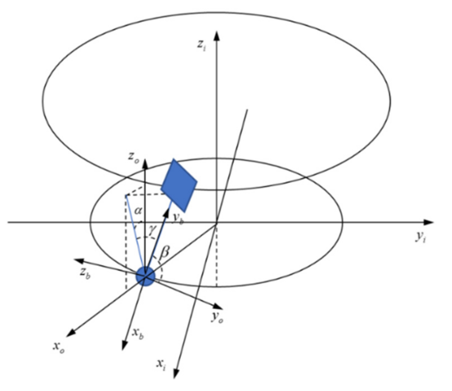
To overcome the singularities, two attitude angles, α and β , are defined in this study of a satellite-sail system, as shown in Figure 2. Based on the new attitude angles, a spacecraft body coordinate system is defined.
Spacecraft body coordinate system S b x b , y b , z b : The origin is coincident with the main satellite and the directions of the axes are shown in Figure 2. The coordinate transformation relationship between S b and S o is defined as follows:
S o R y α R x β S b
Finally, to describe the solar sail attitude, the solar sail body coordinate system is defined.
Solar sail body coordinate system S d x d , y d , z d : As shown in Figure 3, the origin coincides with the center of the solar sail and the z-axis is opposite to the direction of sunlight irradiation, which can be regarded as parallel to the orbital plane since the satellite orbits in a sun-synchronous orbit and the solar–terrestrial distance is much greater than the orbital radius. The x- and y-axes are parallel to the x- and y-axes of S o , respectively.

2.2. Dynamic Model

It is assumed that during a stable deployment, the solar sail is completely unfolded and the tether is tight. In this case, the control forces of the system consist of the solar radiation pressure and the tension on the tether. As the main satellite and the solar sail are both sufficiently small, they could be considered masses in the dynamic model. The following assumptions are considered. The elastic deformation of the tether is insignificant and the tether is extremely light in comparison to the main satellite and the solar sail. The solar sail system in a transverse formation is modeled with reference to the dumbbell model of an ordinary tethered satellite.
The Lagrange equation in generalized coordinates is used for modeling. According to Equation (1), the coordinate transformation matrix between S b and S o could be described as follows:
A b o = cos α 0 sin α sin β sin α cos β sin β cos α cos β sin α sin β cos β cos α
In research on space tethered systems, the control laws of deployment, retrieval, and maintenance are generally designed based on the dumbbell model and a more accurate beads model used for simulation verification. For a space tether system where the mass of the spacecraft at both ends is significantly larger than the mass of the tether, the dumbbell model and simplified model ignore the mass of the tether and are sufficient for simulation and control law design. However, solar sail spacecraft are large enough and light enough. In the simulation of the above study, the mass of the solar sail used is assumed to be 1 kg. The tether material commonly applied in the space tethered system trials is Dyneema. The linear density of a Dyneema tether of 1.5 mm diameter is approximately 1.2 g/m for a 1000 m tether, and thus the mass of the tether is approximately 1.2 kg, which is in the same order of magnitude as the solar sail. Therefore, the mass of the tether is an important factor contributing to model uncertainty during the deployment and retrieval of a satellite-sail system.
In the following, the dumbbell model for a satellite-sail system considering the mass of the tether will be derived based on the Lagrange equation. At this time, in addition to the kinetic and potential energy of the satellites at the ends of the tether, this is in addition to considering the kinetic and potential energy of the tether. The tether is a continuum. Assuming that the mass of the tether is uniformly distributed, the tether could be considered a continuous elementary mass and the kinetic and potential energy of the complete tether could be obtained by integration, as follows:
R m = R c m s + 0.5 m t m l
R s = R c + m m + 0.5 m t m l
where m t = ρ l   ρ is the linear density of the tether and ξ is the distance from the sail to the elementary mass. It is important to note that the mass of the main satellite m 1 is the variable in this case.
m m = m m 0 m t = m m 0 ρ l
where m m 0 is the initial mass of the main satellite.
Firstly, the kinetic energy of the system is calculated. The kinetic energy of the main satellite is calculated as follows:
T m = 1 2 m m d R m d t · d R m d t
The result of deriving Equation (3) is as follows:
d R m d t = d R c d t m s + 0.5 m t m d l d t
Projecting Equation (7) onto the spacecraft body coordinate system, the result is as follows:
V m b = V c b m s + 0.5 m t m l ˙ b m s + 0.5 m t m ω b × l b
ω = ω o b + ω l b
where l b , l ˙ b , ω o b , and ω l b are projections of l , l ˙ , ω o , and ω b in the coordinate system S b separately. The results of the calculations are as follows:
ω b × l b = ω o cos β cos α + sin β α ˙ l 0 ω o sin α + β ˙ l T
Similarly, the kinetic energy of the solar sail is calculated as follows:
T 2 = 1 2 m s d R s d t · d R s d t
The kinetic energy of the tether can be derived from the following integral equation:
T t = 1 2 R ˙ ξ · R ˙ ξ d m = 1 2 ρ 0 l R ˙ ξ · R ˙ ξ d ξ
The final result is shown directly as follows:
T = 1 2 V c 2 m + 1 2 m * ω o cos β cos α + sin β α ˙ 2 + ω o sin α + β ˙ 2 l 2 + m ˜ l ˙ 2
where the expression of the parameters of mass is:
m * = ( m m + 0.5 m t ) ( m m + 0.5 m t ) m 1 6 m t
m ˜ = ( m m + m t ) m s m
Further, the potential energy of the system is calculated. As an example, the gravitational potential energy of the main satellite is as follows:
U m = m m μ R m
Similarly, the gravitational potential energy of the sail and tether are as follows:
U s = m s μ R s
U t = μ R ξ d m = ρ 0 l μ R ξ d ξ
The total potential energy of the system is as follows:
U = m μ R c 1 + 1 2 μ R c 3 m * 3 l · R c 2 R c 2 l 2
Projecting the above equation onto S b and converting to a scalar, the result is as follows:
U = m μ R c 1 + 1 2 μ R c 3 m * 3 sin β sin α 2 1 l 2
Thus, the Lagrange function expression for the system is as follows:
L = T U = 1 2 m * ω o cos β cos α + sin β α ˙ 2 + ω o sin α + β ˙ 2 3 sin 2 β sin 2 α 1 μ R c 3 l 2 + m ˜ l ˙ 2
For circular or near-circular orbits, μ R c 3 = ω o 2 . The final kinetic equations are as follows:
l ¨ = m * m ˜ ω o cos β cos α + sin β α ˙ 2 + ω o sin α + β ˙ 2 + ω o 2 3 sin 2 β sin 2 α 1 l ( 2 m 1 m ) m t m m ˜ l ˙ 2 l Q l m ˜
α ¨ = 2 cos β sin β α ˙ β ˙ 2 ω o β ˙ cos α + 4 ω o 2 sin α cos α 2 m 1 ( m 2 + 0.5 m t ) m m l ˙ l 1 cos α cos β sin β ω o + α ˙ + Q α m * l 2 sin 2 β
β ¨ = 2 ω o sin 2 β cos α α ˙ 2 m 1 ( m 2 + 0.5 m t ) m m l ˙ l 1 ω o sin α + β ˙ + sin β cos β α ˙ 2 + 4 sin 2 α 1 ω o 2 sin β cos β + Q β m * l 2
In Equations (22)–(24), Q l , Q α , and Q β are the generalized forces corresponding to the respective variables. In general, the mass of the main satellite is much greater than the solar sail, where it could be considered m ¯ m 2 . The control force of the system consists of the solar radiation pressure and the tether tension. The generalized forces are related to the control forces as follows:
Q l = F t e + F s y b Q α = F s x b l sin β Q β = F s z b l
where F s x b , F s y b , and F s z b are the projected components of the solar radiation pressure on the three axes of S b and F t e is the tension of the tether.

2.3. Simplified Dynamic Model for Controller Design

Since the rope length is generally of a much larger magnitude than the angular magnitude in practice, causing considerable difficulty in calculation and analysis, the kinetic equations are normalized. The dimensionless time and dimensionless length are defined and expressed as follows:
t ^ = ω o t
Λ = l / l 0
The physical definition of dimensionless time is in fact the true anomaly. l 0 is the nominal length of the tether, which could be either the initial or the target length of the tether. In this paper, l 0 is chosen as the target length.
The dynamic equations are analyzed with dimensionless time and dimensionless length of tether. Alternatively, for the design of the controller, the residual angle γ = π 2 β is substituted for β . Equations (22)–(24) can be expressed as follows:
Λ = sin γ cos α + α cos γ 2 + sin α γ 2 + 3 cos 2 γ sin 2 α 1 Λ ( 2 m 1 m ) m t m m ˜ Λ 2 Λ + F t e + F s y b m ˜ ω o 2 l 0
α = 2 sin γ cos γ α γ + 2 γ cos α + 4 sin α cos α 2 m 1 ( m 2 + 0.5 m t ) m m Λ Λ 1 cos α sin γ cos γ + α + F s x b m * l 0 ω o 2 Λ cos γ
γ = 2 α cos 2 γ cos α sin γ cos γ α 2 4 sin 2 α 1 sin γ cos γ + 2 m 1 ( m 2 + 0.5 m t ) m m Λ Λ 1 sin α γ F s z b m * l 0 ω o 2 Λ
where · = d · d t ^ , · = d 2 · d t ^ 2 .
Under the assumption of small angles (i.e., less than 20°), the higher-order terms of the angles are ignored. Equations (28)–(30) can be expressed as follows:
Λ = ( 2 m m m ) m t m m ˜ Λ 2 Λ + m * m ˜ 2 γ α + 2 γ α 1 Λ + T + F s y b m ˜ ω o 2 l 0
α = 2 γ + 4 α 2 m m m s + 0.5 m t m m * Λ Λ 1 γ + α + F s x b m * ω o 2 l 0 Λ
γ = 2 α + γ 2 m m m s + 0.5 m t m m * Λ Λ 1 α γ F s z b m * ω o 2 l 0 Λ
Then, Equations (31)–(33) can be expressed in state-space equations. Assuming that 0 q 1 is the target length of the tether, the state-space variables are defined as follows:
z 1 = Λ q , z 2 = Λ , z 3 = α , z 4 = α , z 5 = β , z 6 = β
The state-space equations are as follows:
z 1 = z 2 z 2 = ( 2 m m m ) m t m m ˜ z 2 2 z 1 + q + m * m ˜ 2 z 4 z 5 + 2 z 3 z 6 1 z 1 + q + F t e + F s y b m ˜ ω o 2 l 0 z 3 = z 4 z 4 = 2 z 6 + 4 z 3 m m m s + 0.5 m t m m * 2 z 2 z 1 + q z 5 + z 4 + F s x b m * ω o 2 l 0 z 1 + q z 5 = z 6 z 6 = 2 z 4 + z 5 m m m s + 0.5 m t m m * 2 z 2 z 1 + q z 3 z 6 F s z b m * ω o 2 l 0 z 1 + q
To facilitate the design of the controller, the nonlinear dynamic Equation (35) is linearized. Considering z 1 and z 2 as small quantities, the linearized first-order approximation model is obtained by expanding at point 0 0 0 0 0 0 , as follows:
Z = C Z + B u
where
C = 1 m * m ˜ 1 4 2 1 2 1 , Z = z 1 z 2 z 3 z 4 z 5 z 6 , B = 0 0 0 1 0 0 0 0 0 0 1 q 0 0 0 0 0 0 1 q u = m * m ˜ q + u 1 u 2 u 3 , u 1 = F t e + F s y b m ˜ ω o 2 l 0 , u 2 = F s x b m * ω o 2 l 0 , u 3 = F s z b m * ω o 2 l 0
According to the stability in the first approximation, it is known that the stability analysis of the nonlinear system (35) can be transformed into the stability analysis of the linear system (36).
Theorem 1.
If all eigenvalues of the matrix A contain negative real parts and h ( t , x ) = o ( x ) holds consistently in the interval 0 , , then for the differential equation x ˙ = A x + h ( t , x ) , any solution x ( t ) satisfying x ( 0 ) sufficiently small always exists and the solution x = 0 is asymptotically stable.
According to the simplified linear Equation (36), it can be seen that the length of the tether is decoupled from the angles in the small-angle case of the transverse formation.
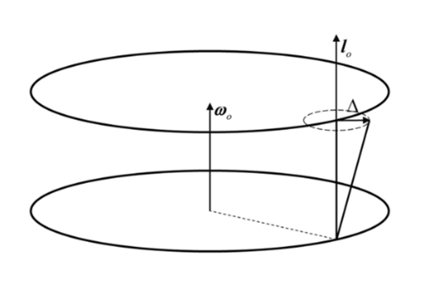
The physics of this conclusion can be explained. As shown in Figure 4, the effect of tether velocity on the angular velocity is reflected in the Coriolis force; however, the Coriolis force is remarkably insignificant due to the fact that the tether velocity is in the same direction as the angular velocity and the cross product is equal to zero. Hence, the effect of tether velocity on the angular velocity can also be neglected. According to the above conclusion, only for the traverse formation, the controller of angle and the controller of tether length could be designed separately under the assumption of small angles.

2.4. Beads Model for Satellite-Sail System

The space tether system is a complex nonlinear system, and it is further complicated by features with the coupled solar sail attitude and orbit, which results in a more complex satellite-sail system model. Model uncertainty is one of the factors that have a large impact in the control of satellite-sail systems. In this chapter, the influence of the mass of the tether on the state of the satellite-sail system is investigated. A model with high accuracy based on the beads model for a tethered system is developed to investigate the result of the controller under the high-accuracy model. The effect of model uncertainty on the rope-system solar sail system is discussed.
The dumbbell model cannot describe the flexibility of the tether, and in several cases the dumbbell model cannot describe the characteristics of the tethered system accurately, especially in the simulation; therefore, the dumbbell model is not accurate enough and a more accurate model is required.
The beads model describes the motion of the tether and simulates the configuration change of the tether more explicitly and accurately. An accurate model, the beads model has extensive application in the accurate dynamic simulation of tethered systems, although it has several disadvantages. The accuracy of the model depends hugely on the number of beads, and as the number of beads increases, the computational effort increases rapidly and computational speed becomes slower. Therefore, the beads model is generally applied as an accurate model for simulation and not for the design of control laws.
The basic structure of the beads model is shown in Figure 5. The space tethered system is discretized into N beads connected by springs without mass, and the mass of each section of the tether is concentrated at the point. The dispersion of the tether can be asymmetrical and the density also. The system is transformed into a multibody system consisting of N + 2 rigid bodies. The distributed and concentrated forces are transformed into the forces and moments on the main satellite, the subsail, and the beads according to the principle of force equivalence.
The dynamics of the main satellite and beads are similar to the beads model for a general space tethered system, except that the solar radiation pressure on the solar sail instead of a general subsatellite is considered. The dynamic equations could be as follows:
m m d 2 R m d t 2 = μ m m R m 3 R m + f m + g m + U m , F
m s d 2 R s d t 2 = μ m s R s 3 R s f s + g s + F s
m i d 2 R i d t 2 = μ m i R i 3 R i f i + 1 + f i + g i
where f is the tension of the segments of the tether, g is the perturbative force, U is the control force of the main satellite, F s is the solar radiation pressure, and i is the number of a bead ( i = 1 , 2 , N 1 ).

3. Design of Control Law

3.1. Parameter Selection of the Sail

In Section 2.1, the solar sail body coordinate system S d x d , y d , z d is defined. The solar sail attitude angle φ 1 , φ 2 is defined, as shown in Figure 3. According to the geometric relations, the normal direction of the sail could be expressed in S d as n = sin φ 1 cos φ 2 sin φ 1 sin φ 2 cos φ 1 T . Therefore, the expression for the solar pressure is as follows:
F s = m 2 ξ μ s r s d 2 cos 2 φ 1 n
Since the sun–Earth distance is much larger than the orbital radius and the length of the tether, i.e., r s e R c l , r s d r s e could be considered in the research. ξ is the solar sail lightness number, which is constant for a specific solar sail and is related to the area-mass ratio.
According to [7], to produce a planetary displaced orbit when the solar sail is affected by the gravity of the planet and the solar radiation pressure only, the magnitude of the solar radiation pressure and the height of the planetary displaced orbit satisfy the equation as follows:
F s = ω o 2 1 + λ h 2 1 ω d ω o 2 2 3 2 h
where λ is the distance between the solar sail and the planet, h is the distance between the plane of the displaced orbit and the plane of the geocentric orbit parallel to it, and ω d is the angular velocity of the displaced orbit. The calculation of ω d is as follows:
ω d = μ λ 2 + h 2 3 2
For this study h l 0 λ , and it might be concluded that λ 2 + h 2 R c and ω d ω o . Therefore, F s ω o 2 l 0 . According to Equation (40), the solar radiation pressure is F s = ξ μ s r s d 2 . It could be known from the analysis above that for a solar sail planetary displaced orbit affected only by gravity of the planet and solar radiation pressure, the solar pressure coefficient ξ is determined after determining the required orbital radius and h . However, for the satellite-sail system investigated in this paper, the solar sail is additionally affected by the tension of the tether; therefore, in the selection of parameters related to the solar sail, it may not be necessary to follow Equation (40). In this paper, the solar radiation pressure is F s = 3 ω o 2 l 0 . In this case, ξ = 0.4993 is required, which means the surface to mass ratio is 3.0641 g/m2.
The ideal force model of solar pressure is described in Equation (40), which is suitable only for a perfectly reflective sail. In a more realistic case, the expression for the solar pressure could be approximated as the value of ideal model multiplied by an optical efficiency factor K , which is as follows:
F s = m 2 ξ K μ s r s d 2 cos 2 φ 1 n

3.2. Controller Design

There are two main methods for deployment and retrieval of tethered satellite system—length rate control and tension control—both of which are essentially the same, except for the control quantity output by the actuators. However, in the deployment/retrieval process of solar sail systems, if the effect of the perturbative force is not considered, the variation in length of the tether, i.e., the relative distance between the solar sail and the main satellite, is affected by both the solar radiation pressure and the tension of the tether, which requires that the magnitudes of the above two forces are essentially the same. For solar sail spacecraft in low-Earth orbit, the solar radiation pressure on the solar sail is of a magnitude of 103 N. Therefore, the tension on the tether is generally of a magnitude of 103 N. This presents a challenge for the design of the actuator. For the deployment mechanism of a tethered satellite, tensions as small as 103 N would make it difficult to achieve accurate values without additional thrust assist. Length rate control is an effective alternative solution. The tether is released by this method at a specified rate determined by real-time calculations, and it is a more convenient method for the actuator to provide an accurate required speed than to provide the required tension. Therefore, we design a control law for the deployment/retrieval process of a satellite-sail system with a length rate control method in this paper.
Firstly, the tether length trajectory of the deployment process is designed, which is implemented with a cubic function. The trajectory is presented as:
l t = a t 3 + b t 2 + c t + d l < l max l max l l max
Equation (46) can be expressed in dimensionless length of tether and dimensionless time, and the result is as follows:
Λ t ^ = a ^ t ^ 3 + b ^ t ^ 2 + c ^ t ^ + d ^ Λ < 1 1 Λ 1
where a ^ = a ω o 3 l 0 , b ^ = b ω o 2 l 0 , c ^ = c ω o l 0 , d ^ = d l 0 . Substituting Equation (45) into the dynamic Equations (32) and (33), the result is as follows:
α = 2 γ + 4 α 2 m m m s + 0.5 m t m m * Λ t ^ Λ t ^ 1 γ + α + F s x b m * ω o 2 l 0 Λ t ^
γ = 2 α + γ + 2 m m m s + 0.5 m t m m * Λ t ^ Λ t ^ 1 α γ F s z b m * ω o 2 l 0 Λ t ^
Defining y 1 = α , y 2 = α , y 3 = β , y 4 = β , Y = y 1 , y 2 , y 3 , y 4 T , u = F x b m * ω o 2 l max , F z b m * ω o 2 l max T , Equations (46) and (47) can be written as:
Y = C t ^ Y + B t ^ u
where:
C = 1 4 2 M Λ t ^ Λ t ^ 2 M Λ t ^ Λ t ^ 2 1 2 M Λ t ^ Λ t ^ 2 1 2 M Λ t ^ Λ t ^ ,   B = 0 1 Λ t ^ 0 0 0 0 0 1 Λ t ^ ,   M = m m m s + 0.5 m t m m *
System (48) is a linear time-varying system. The control law for angles is designed with the time-varying LQR method. The expression of the designed value function is as follows:
J = 1 2 0 Y T Q Y + u T R u d t
where Q and R are a positive definite matrix. According to LQR control theory, if there exists a time-varying positive definite matrix P t ^ that satisfies the following Riccati equation at each moment of time:
C t ^ T P t ^ + P t ^ C t ^ P t ^ B t ^ R 1 B t ^ T P t ^ + Q = 0
when u t ^ = R 1 B t ^ T P t ^ Y t ^ , then the equation is stable.

3.3. Allocating Angles of the Sail and Tension

With the projection of the control forces into the coordinate system S d for analysis, according to Section 2.1, since the direction of sunlight irradiation could be considered perpendicular to the orbital plane, it means that A b d = A b o and F s d = A d b F s b . Therefore, the relationship between the projections of solar radiation pressure is as follows:
m 2 ξ μ s r s d 2 cos 2 φ 1 sin φ 1 cos φ 2 cos 2 φ 1 sin φ 1 sin φ 2 cos 3 φ 1 T = A o b F s x b F s y b F s z b T
Equation (51) is considered a nonlinear system of equations F x = 0 , x = F s y b , φ 1 , φ 2 T . According to Equation (48), F s x b and F s z b are known and given by control law. The attitude angle of the solar sail during deployment and F s y b could be determined by solving the nonlinear system of equations with Newton’s iterative method. The magnitude of the tension is calculated by F s y b and Equation (25).

4. Simulation and Results

Assuming that the dimensionless time at the end of the deployment is t ^ f , Parameters for simulation are shown in Table 1 to ensure that Λ 0 = Λ t ^ f = 0 , Λ t ^ f = 1 , the parameters a = 2.0324 × 10 9 ,   b = 3.0242 × 10 5 ,   c = 0 ,   d = 8 are selected during the process of deployment.
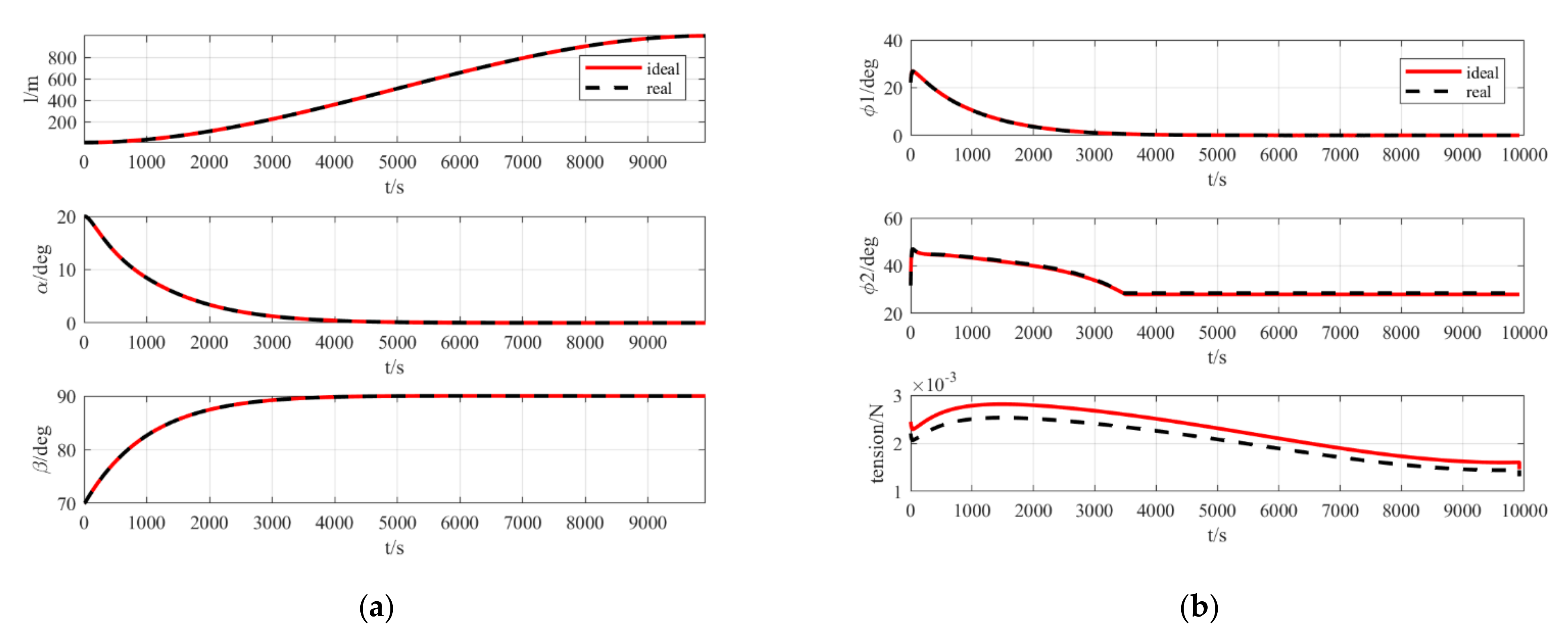
The variation of states is shown in Figure 6a. It can be noticed that the deployment process is completely stable. The length of the tether reaches the target value in about 10,000 s and the two attitude angles reach the target values in about 6000 s. The variation in control input is as shown in Figure 6b. The tension of the tether is always positive, which satisfies the requirement that the tether can only be stretched and not stressed, and the satellite-sail system is successfully deployed.
During the process of retrieval, a = 2.0324 × 10 9 ,   b = 3.0242 × 10 5 ,   c = 0 ,   d = 1000 are selected. The variation of states is shown in Figure 7a. Again, the retrieval process is steadily completed. The length of the tether is recovered to the target value in about 10,000 s and the two attitude angles reach the target values in about 7000 s. The variation of control input is as shown in Figure 7b. The tension of the tether is always positive, and the satellite-sail system is successfully recovered.
The cases for the ideal model and a more realistic model are both discussed in simulation K = 0.9 . The other results are similar, but the tension of the real model is smaller than the ideal model in either deployment or retrieval, because the solar radiation pressure of the real model is smaller than the ideal model.
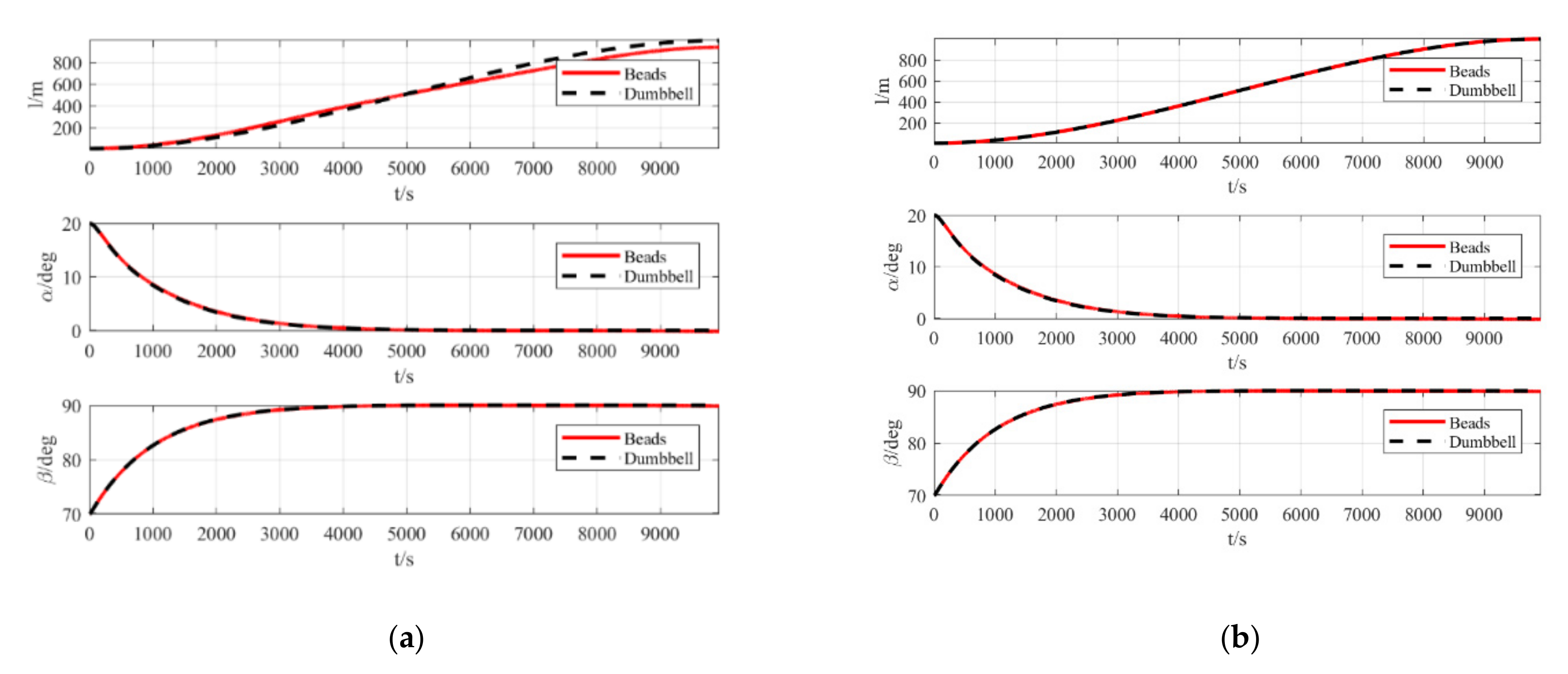
The control law of deployment designed in 4.2 is directly applied to the beads model and the number of beads N = 10 is selected. The results are compared with the dumbbell model, which considers the mass of the tether in Figure 8a.
According to the simulation results, the two attitude angle-variation strategies of the dumbbell model and the beads model in the deployment process are almost the same; however, for the variation strategy of length, there is a certain difference between the two models, which might be caused by the elasticity and flexibility of the tether considered in the beads model. Model predictive control (MPC) is used to deal with this problem. Considering the state trajectory of the dumbbell model as the reference trajectory, the results obtained are shown in Figure 8b.

5. Conclusions

The conclusions of this paper are as follows:
(1) In this research, based on the Lagrange equation, the dynamics of the satellite-sail system applicable to the transverse formation are modeled with reference to the dumbbell modeling method of the general space tethered system under the avoidance of singular attitude angle description. A simplified linear model applicable to the design control law is also proposed on the basis of the theory of linear autonomous systems. The model with small angles is linearized by the stability in the first approximation. It is concluded that the length is decoupled from the two attitude angles in the case of a small-angle transverse formation configuration, and this conclusion is explained physically, leading to the conclusion that the length and the two attitude angles could be designed separately in the controller. Meanwhile, a dumbbell model of a satellite-sail system with mass of tether and a more accurate beads model with the flexibility of the tether are developed.
(2) On the basis of the method of velocity control of the tethered satellite, a control law for both deployment and retrieval was designed. The deployment and retrieval of the tether is at a specified velocity determined by real-time calculations, and the angles are controlled by time-varying LQR method. Simulation results demonstrate that the control strategy allows the states to converge steadily to the target value, and the tether tension is always positive. The simulation results show that there are some differences in the states of the beads model and the dumbbell model during the deployment process. This might be caused by the flexibility and elasticity of the beads model. The MPC controller is used to solve the problem.

Author Contributions

Conceptualization, R.Z.; Investigation, Y.Z.; Software, Y.Z.; Supervision, R.Z.; Writing—original draft, Y.Z.; Writing—review and editing, R.Z. All authors have read and agreed to the published version of the manuscript.

Funding

This research was funded by the Fundamental Research Funds for the Central Universities.

Conflicts of Interest

The authors declare no conflict of interest.

Nomenclature

A = coordinate-transformation matrix
A = cross-sectional area of tether
e = base vector of coordinate system
E = stiffness of tether
F s = solar radiation pressure, N
F t e = tension of tether, N
l = vector of the main satellite pointing towards the solar sail
l = length of tether, m
m = mass of the particle, kg
n = normal vector of sail
r s e = sun–Earth distance, m
r s d = sun–sail distance, m
R = vector of the center of the Earth pointing towards the particle
t ^ = dimensionless time
T = kinetic energy
U = potential energy
V = velocity of a particle
α , β , γ = attitude angle for satellite-sail system, rad
Λ = dimensionless length of tether
μ = geocentric gravitational constant, m3/s2
μ s = heliocentric gravitational constant, m3/s2
ξ = solar sail lightness number
ρ = linear density of tether, kg/m
φ 1 , φ 2 = attitude angle for solar sail
ω o = orbit angular velocity, rad/s
ω l = angular velocity of satellite-sail system moving around the center of mass, rad/s
Subscripts
m = main satellite
s = solar sail
c = barycenter of system
i = the i’th bead

References

  1. Alfriend, K.T.; Vadali, S.R.; Gurfil, P.; How, J.P.; Breger, L. Spacecraft Formation Flying: Dynamics, Control and Navigation; Elsevier: Amsterdam, The Netherlands, 2009. [Google Scholar]
  2. Murray, N.J.; Keith, D.A.; Bland, L.M.; Ferrari, R.; Lyons, M.B.; Lucas, R.; Nicholson, E. The role of satellite remote sensing in structured ecosystem risk assessments. Sci. Total Environ. 2018, 619, 249–257. [Google Scholar] [CrossRef] [PubMed] [Green Version]
  3. Schaub, H.; Alfriend, K.T. J2 invariant relative orbits for spacecraft formations. Celest. Mech. Dyn. Astron. 2001, 79, 77–95. [Google Scholar] [CrossRef]
  4. Abd El-Salam, F.A.; El-Tohamy, I.A.; Ahmed, M.K.; Rahoma, W.A.; Rassem, M.A. Invariant relative orbits for satellite constellations: A second order theory. Appl. Math. Comput. 2006, 181, 6–20. [Google Scholar] [CrossRef]
  5. Xu, M.; Wang, Y.; Xu, S. On the existence of J2 invariant relative orbits from the dynamical system point of view. Celest. Mech. Dyn. Astron. 2012, 112, 427–444. [Google Scholar] [CrossRef]
  6. Xu, M.; Xu, S. J2 invariant relative orbits via differential correction algorithm. Acta Mech. Sin. 2007, 23, 585–595. [Google Scholar] [CrossRef]
  7. Pan, X.; Xu, M.; Dong, Y.; Zuo, X. Relative Dynamics and Station-Keeping Strategy of Satellite–Sail Transverse Formation. J. Guid. Control Dyn. 2020, 43, 2156–2164. [Google Scholar] [CrossRef]
  8. Zakrzhevskii, A.E. Method of deployment of a space tethered system aligned to the local vertical. J. Astronaut. Sci. 2016, 63, 221–236. [Google Scholar] [CrossRef]
  9. Yu, S. Tethered satellite system analysis (1)—Two-dimensional case and regular dynamics. Acta Astronaut. 2000, 47, 849–858. [Google Scholar] [CrossRef]
  10. Rupp, C.C. A Tether Tension Control Law for Tethered Subsatellites Deployed along Local Vertical; NASA STI/Recon Technical Report NASA TM X-64963; NASA: Washington, DC, USA, 1975.
  11. Zhong, R.; Xu, S.J. Simple tension control strategy for variable length tethered satellite system. Chin. Space Sci. Technol. 2009, 29, 66. [Google Scholar]
  12. Kumar, K.D.; Yasaka, T. Rotation formation flying of three satellites using tethers. J. Spacecr. Rockets 2004, 41, 973–985. [Google Scholar] [CrossRef]
  13. Steindl, A.; Troger, H. Optimal control of deployment of a tethered subsatellite. Nonlinear Dyn. 2003, 31, 257–274. [Google Scholar] [CrossRef]
  14. Williams, P. Optimal deployment/retrieval of tethered satellites. J. Spacecr. Rockets 2008, 45, 324–343. [Google Scholar] [CrossRef]
  15. Zuo, X.; Pan, X.; Xu, M.; Ma, L.; Zhang, J. Deployment strategy for satellite-sail transverse formation. Acta Astronaut. 2021, 186, 242–251. [Google Scholar] [CrossRef]
Figure 1. Transverse formation.
Aerospace 09 00602 g001
Figure 2. Definition of coordinate systems for traverse formation.
Aerospace 09 00602 g002
Figure 3. Solar sail body coordinate system.
Aerospace 09 00602 g003
Figure 4. Physical interpretation of the decoupling of length and angle.
Aerospace 09 00602 g004
Figure 5. Beads model.
Aerospace 09 00602 g005
Figure 6. (a) State trajectory during the deployment of a satellite-sail system; (b) control input trajectory during the deployment of a satellite-sail system.
Aerospace 09 00602 g006
Figure 7. (a) State trajectory during the retrieval of a satellite-sail system; (b) control input trajectory during the retrieval of a satellite-sail system.
Aerospace 09 00602 g007
Figure 8. (a) State trajectory of beads model; (b) state trajectory of beads model (with MPC).
Aerospace 09 00602 g008
Table 1. Parameters for simulation.
m m / k g m s / k g l max / m Q R
10011000 d i a g 1 , 1 , 100 , 100 d i a g 100 , 100
Initial LengthTarget LengthInitial  α Target  α Initial  β Target  β
Deployment0.008120°70°90°
Retrieval10.00889°90°
Publisher’s Note: MDPI stays neutral with regard to jurisdictional claims in published maps and institutional affiliations.