Article

An Effective Form Analysis Approach for Designing and Optimizing a Cable-Net Structure of a Giant Active Reflector

School of Ocean Engineering, Harbin Institute of Technology at Weihai, Weihai 264209, China
*
Authors to whom correspondence should be addressed.
Aerospace 2021, 8(9), 269; https://doi.org/10.3390/aerospace8090269
Submission received: 21 May 2021 / Revised: 25 August 2021 / Accepted: 17 September 2021 / Published: 18 September 2021

Abstract

:
The cable-net structure of a giant active reflector is a structure with large deformations. The effective form analysis approach can help the active reflector to achieve high surface accuracy. In this paper, a new nonlinear numerical form analysis approach is proposed for the active reflector cable-net structure. The basic principle and calculation flow of the static equilibrium are provided and the calculation program is compiled. This approach does not only achieve a uniform cable tension design based on the idea of “equal-tension replacement” but also simulates the change process from the reference state to the target working state. The obtained final form conforms to the target configuration and achieves the force balance. This, in turn, proves the adaptability of the proposed approach for the design and optimization of active reflector cable-net structure. By employing the form analysis, the length change of actuators and force distribution of all cables can also be simultaneously obtained. This provides an important basis for the actual operation and control optimization of similar active reflectors.

1. Introduction

Due to its light weight, strong adaptability, and ability to be adjusted into various required functional forms, the cable-net structure is often employed as a common supporting structure for large telescope active reflectors. The giant active reflector has to meet many special observation requirements in the actual operation. Thus, this type of cable-net structure can be regarded as a structure with relatively large deformations. Form determination of the cable-net plays a vital role in the surface accuracy of the active reflector, which directly affects the observation accuracy of a radio telescope [1]. The mechanical performance of the reflector cable-net is also important. Higher surface accuracy and excellent stress distribution can be obtained by employing a numerical analysis approach.
Since the 1960s, researchers have conducted many investigations on form analysis approaches of the active reflector cable-net structures. Among them, the comparatively mature approaches are the force density method (FDM), the dynamic relaxation method (DRM), and the nonlinear finite element method. FDM [2,3,4] was first proposed by Linkwitz and Schek for the form-finding analysis of tensile structures such as cable nets. Tanka et al. [5], Morterolle et al. [6], Yang et al. [7], and Maddio et al. [8] applied FDM to the form-finding analysis of the AstroMesh reflector (The AstroMesh reflector is a mesh reflector for large aperture space antenna systems and is a type of ring truss developable structure. With increasing aperture, the mass per unit area decreases and the reflector can maintain high surface accuracy. Thus, the AstroMesh is widely used [9,10]). Yang et al. [11] also proposed a new and improved form-finding technique based on FDM to achieve a uniform cable tension design. Day proposed the DRM in 1960 [12,13,14]. The principle of this method is to find the position of maximum kinetic energy, which is the equilibrium state of the structure. Wang et al. [10] utilized two different types of AstroMesh reflectors as numerical examples to verify the feasibility of this method. In recent years, other types of nonlinear finite element methods have also been developed and applied to the form-finding research of telescope reflectors. Ma et al. [15] and Li et al. [16] proposed a two-step form-finding method to systematically determine cable force distribution. Yuan et al. [17,18,19] introduced the fixed nodal position method to find the equilibrium state of the AstroMesh reflector. The authors concluded that this new geometric design method further improved the surface accuracy of the reflector. Li et al. [20] combined the FDM with the minimum norm method (MNM) to obtain the reflector form. This, in turn, improved the process of obtaining the effective area of the reflector, which is decreased when only FDM is used to find the form. Nie et al. [21,22] proposed a form-finding method with varying topologies and parameters. This method provided an important deployment basis for the design and control of the cable-net reflector structure.
Traditional form analysis approaches often have limitations in their application, especially for large deformation problems such as ill-conditioned stiffness matrix and iterative non-convergence. In this paper, a form analysis approach based on Vector Form Intrinsic Finite Element (VFIFE) is proposed for the active reflector cable-net structure. VFIFE is a new type of numerical analysis method that was proposed by Ting et al. in 2004 [23,24,25]. Many researchers have successfully expanded the application range of the VFIFE method from the original rod element to the membrane element [26,27] and the solid element [28]. Moreover, the VFIFE method has also shown adaptability when dealing with strong nonlinear problems in engineering. Lien et al. [29,30] studied the nonlinear behavior of steel structures exposed to fire. Duan et al. [31] combined the VFIFE-J integral and VFIFE-FCM methods to simulate the expansion of elastic and cohesive cracks. Xu et al. [32,33] analyzed the impact of initial defects on the submarine pipeline in various environments. The aforementioned research demonstrates that the VFIFE method has good stability, convergence, and calculation accuracy in strongly nonlinear problems.
In this paper, an effective form analysis approach is proposed based on the VFIFE to design and optimize the cable-net structure. First, a numerical example of a real active reflector cable-net structure, which is the world’s largest radio telescope, is shown. Then, basic principles for solving the static equilibrium of the active reflector structure based on the VFIFE are proposed. Furthermore, the idea of “equal-tension replacement” is used to optimize the section. Finally, the active reflector form is analyzed and uniform tension design is achieved. To explore the feasibility and correctness of the proposed form analysis approach, the final target configuration and the force balance are tested.

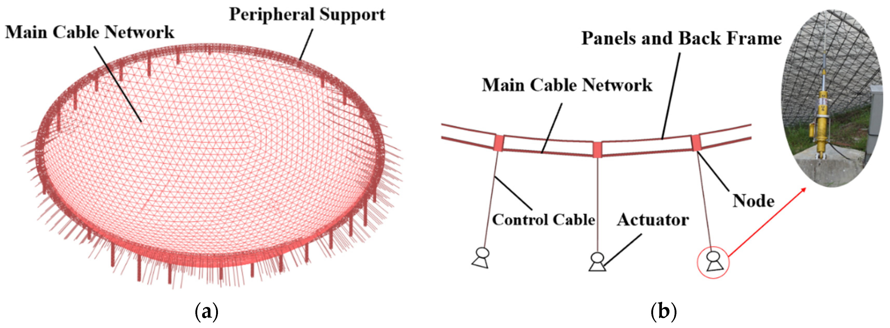
2. Cable-Net Structure of the Active Reflector

The active reflector can achieve synchronous adjustment of the irradiation range with respect to designated paraboloids following the movement of the observed celestial body. Five-hundred-meter Aperture Spherical Telescope (FAST) [1] has the largest active reflector, which is taken as the numerical example in this study.
FAST adopts the reflector scheme of a flexible cable-net structure and a back frame structure. In Figure 1, the FAST active reflector is shown. The main cable-net is supported on the peripheral beam truss. There are 6980 main cables in total. In addition, 4450 triangular reflector panels with 11 m side length are laid on the main cable-net and is supported on the back frame structure. The back frame structure with stiffness acts on main cable nodes in the form of loads. The main cable node is connected to a control cable, and the lower end of the control cable is connected to an actuator. The position of the main cable node is controlled by adjusting the length of the actuator to achieve deformation of the reflector from the spherical surface to the target configuration.
There are two active reflector states: the reference state and the working state. In Figure 2, a cross-sectional relationship between the reference state and a certain working state is demonstrated. The parameter β indicates the angle between the irradiation direction and the vertical plane. Here, it is assumed that β = 0°. In the reference state, the reflector is a defined spherical surface with an aperture of 500 m and a radius of curvature of 300 m. There are numerous reflector forms in the working state which continuously change over time. However, the working surface within the irradiation range is a designated paraboloid with an aperture of 300 m and a focal length of 0.4665R. The transition from the reference state to the working state is achieved by varying the length of different actuators.
The form analysis in this paper includes form-finding analysis and form deformation analysis. The form-finding analysis is to determine the reference spherical surface with uniform tension. On the other hand, the form deformation analysis is to simulate the change process from the reference state to the target working state. The working state studied in this paper is the designated paraboloid with an irradiation direction β = 0°. The process of adjusting the reflector cable-net structure from the reference state to the designated working state is analyzed in detail.

3. Basic Form Analysis Principles of the Reflector Cable-Net Structure

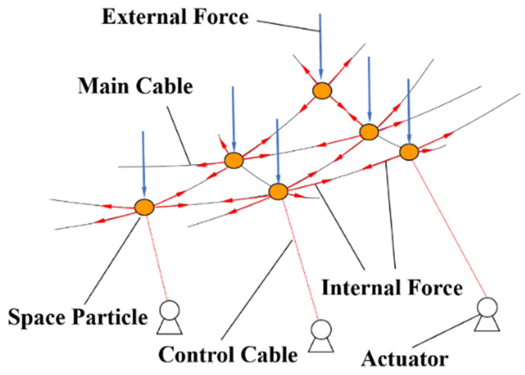
3.1. Structural Discretization and Motion Description

It is assumed that the connection of the reflector cable-net structure is hinged, and the influence of the node stiffness can be neglected. As shown in Figure 3, the cable-net structure is directly decomposed into many link elements and corresponding space particles. The geometric shape and spatial position of the structure are described by the motion of space particles. The mass of a space particle includes the joint concentrated mass and the element equivalent mass. To simplify the calculation process, the element mass is evenly distributed among the space particles at both ends. The total mass of space particles is calculated according to Equation (1):
m i   = M i   + ( j n m ij ) / 2
where m i denotes the total mass at the space particle i, M i denotes the concentrated mass of the particle, m ij denotes the mass of the element ij, and i and j are the numbers of the nodes at both ends of the element.
The internal forces originate from the deformation of the element that is determined by the change of the relative position of space particles and are related to the element material and section. The external forces include the forces acting directly and indirectly on the space particles, where the latter refers to the equivalent forces acting on the elements.
The time history is divided into a finite number of tiny time steps, Δ t . The superposition of the motion on each micro-segment is used to describe the overall trajectory of space particles, which approximates the continuous motion of the structure in space and time. It is assumed that the entire analysis time history is [ t 0 ,   t f ]. Furthermore, a series of time points t 0 , …, t a ,   t b ,   t c , …, t f   are used to divide the total time into a certain number of periods. If the motion of a space particle in a certain period [ t a ,   t b ] satisfies the standard governing equation, the calculation trajectory of the space particle in this period is denoted as the path element, as shown in Figure 4. The structural behavior remains continuous within the path element. Material properties and the stress states of the space particles are regarded as constant values, and the motion of the space particles is approximately regarded as linear. If the period of a path element is small enough, strain and stress increments of the element are considered very small. Thus, the problem of large displacement and large deformation can be simplified to the problem of large displacement and small strain. Therefore, the internal force calculation of some discontinuous structural behaviors can be simplified.

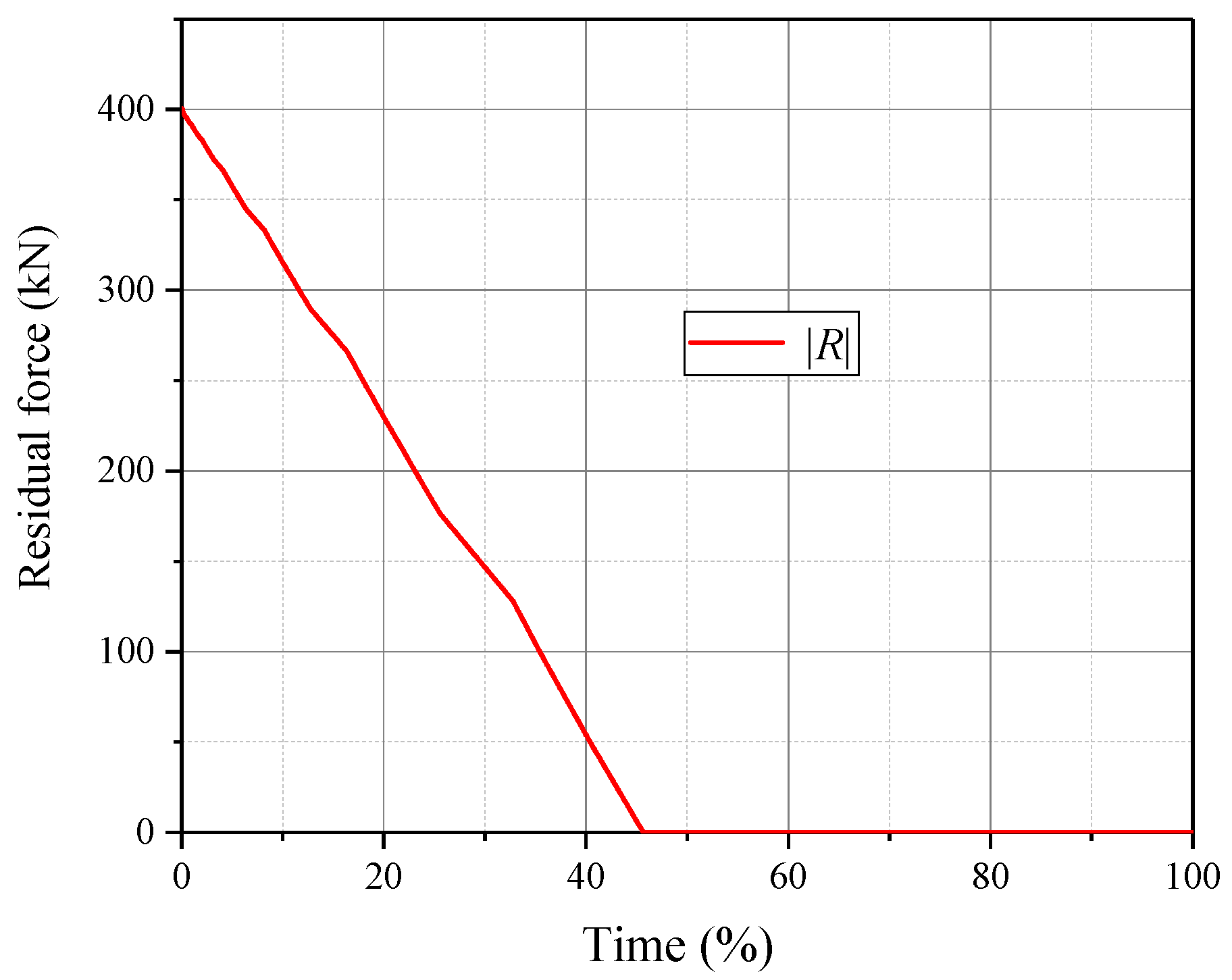
3.2. Principles for Solving Static Equilibrium

After making a simplified motion description by introducing the path element, a set of basic rules (called governing equations) for regulating the structure motion and deformation is established. The governing equations include three physical laws: the law of conservation of mass, the law of motion, and Hooke’s law. In this paper, the motion of space particles follows Newton’s second law.
By employing the path elements to describe and governing equations to regulate structural motion, solving the final static equilibrium state of the structure becomes the key to solving the form analysis problem. Static equilibrium is a common assumption in traditional structure and stress analysis. The space particles keep moving under the action of unbalanced external forces. If there is no mechanism for energy dissipation, the space particles will continue to vibrate like an undamped spring. If an energy dissipation mechanism is presented, the amplitude of the space particles will gradually decrease and eventually converge to a nearly stationary state. This is the principle applied in this paper to solve the final equilibrium state of the reflector cable-net structure.
An energy dissipation mechanism can be added to the particle motion equation to calculate the convergence position. As shown in Equation (2), a virtual damping force F D is added to motion equation to achieve energy consumption. The governing equation can be expressed as:
F D = ζ m i x ·
m i x ¨ = F n + F D = F n ext + F n int + F D
where ζ denotes an arbitrary damping coefficient. This does not have to be the actual damping of some material. Furthermore, the damping coefficient can be assumed as a positive number for the sake of numerical calculation. Parameters x , x · and x ¨ denote the displacement vector, the velocity vector, and the acceleration vector of space particles, respectively.   F n ext denotes the external force on space particles, F n int represents the internal force on space particles, and F n denotes the resultant force vector of the particle. This excludes the virtual damping force, F n = [ F x , F y , F z ].
F n int is derived from the element deformation, which is related to the element material and section. Following the assumption of material mechanics, the element deformation is within the elastic range. Pure axial deformation of element Δ l is obtained from the difference between the element length l t at time t and element length l 0 at time t 0 , as shown as Equation (4):
Δ l = l t     l 0
The internal force at time t is calculated according to Equation (5):
F n int = ( f 0 + EA   ×   Δ l / l 0 ) e 0
where A denotes the element area, E denotes the elastic modulus of the material, f 0 denotes the internal forces of the element at a time t 0 , and e 0 denotes the direction vector of the element at a time t 0 .
The explicit time integration method is used to solve the governing equation. Both x and F n are functions of time t, t = t n   = nh   ( n     0 ) , h is the step size of the time increment, which is assumed as constant. Lastly, n = 0 is the initial step. Both the velocity vector x n ˙ and the acceleration vector x ¨ n of the particle are obtained by employing the central difference method, as shown in Equations (6) and (7):
x n ˙ = (   x n + 1   -   x n - 1   ) / 2 h
x ¨ n = (   x n + 1   -   2 x n   + x n - 1   ) / h 2
where x n - 1 ,   x n , and x n + 1 denote the displacement vectors of the particle at time steps (n − 1), n, and (n + 1).
Equations (2), (3), (6), and (7) can be combined to obtain the particle motion difference (Equation (8)). Relevant coefficients are shown in Equations (9) and (10):
{ x 1 = h 2 F 0 / 2 m i   +   h   ( 1   -   ζ h / 2 )   x 0 ˙   +   x 0   n   =   0 x n + 1 = ( h 2 F n / m i   +   2 x n   -   c 2   x n - 1 ) / c 1 n     1
c 1   =   1   +   ζ h / 2
c 2   =   1   -   ζ h / 2
To summarize, as shown in Figure 5, the steps for solving static equilibrium by VFIFE are as follows. The cable-net structure is first discretized. Then, under the control of the governing equations and mechanism for energy dissipation, x n + 1 can be obtained via Equation (8) from x n - 1 , x n , F n ext , and F n int . In the meantime, the change of node coordinates x n + 1   -   x n results in the change of element length Δ l (Equation (4)). Next, F n + 1 int is obtained by employing Equation (5) and F n ext is updated to F n + 1 ext . Finally, the aforementioned steps are repeated until the structure reaches equilibrium state.

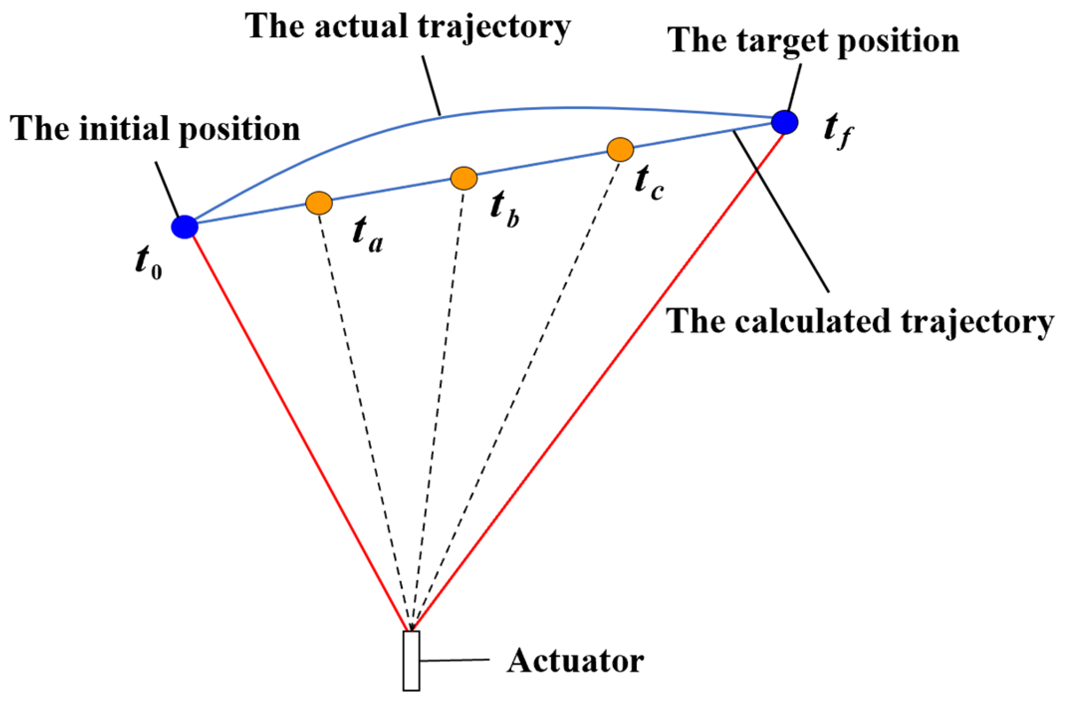
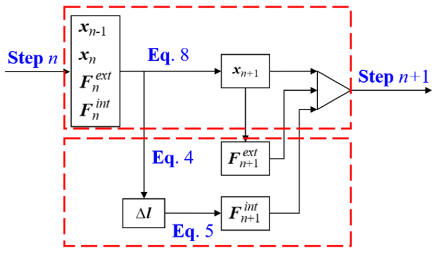
3.3. Iterative Principle and Basic Flow of Form Analysis

Iterative principle and basic flow of form analysis are illustrated with the example of form-finding analysis. The principle starts and ends with the preset reference spherical surface. According to Figure 6, the main cable node gradually moves to the target equilibrium position. In the initial state where no force is present, the main cable node is on the preset reference spherical surface A1. Then, by the combined action of the prestress, the weight of the cable-net, and other external loads, the main cable node reaches a balanced state at position A2. The distance between the position of the main cable node and the reference spherical surface is denoted as d. Next, the forced displacement towards the reference spherical surface is applied to the node and the length of the control cable is simultaneously adjusted. At this point, the VFIFE method is used to find the equilibrium form. After one iteration, the main cable node reaches an equilibrium state in position A3. At this point, the distance between the position of the main cable node and the reference spherical surface is d1, i.e., d1 < d. Then, the iterative process is repeated to ensure that the main cable node is gradually returned to the original reference spherical surface. Simultaneously, the structural residual force |R| is calculated. The residual force |R| is the maximum unbalanced force of all nodes in the iteration process. Moreover, it is the combined force of the prestress, the external force, and the internal force. When the node is in position A1 and the residual force |R| is less than the accuracy requirement, it is considered that the cable-net structure reaches the target configuration and the equilibrium state.
The basic calculation flow of the form analysis is shown in Figure 7. To prevent the stress of some main cables from exceeding the designed strength value of normal cable-net structures, it is necessary to optimize the section of cables. This is also beneficial when the rate of strength utilization of some main cables is relatively low. The idea of “equal-tension replacement” is used to determine the section of cables. The specific steps of the cross-section optimization are as follows:
Step 1: The structure in reference state and the internal force [ F i ] are first obtained.
Step 2: Considering the particularity and importance of telescope structures, according to China Technical Specification for Cable Structures [34], the reference stress level σ is set as 450 MPa. Then, the theoretical area of each cable is defined as A 0 i   =   F i / σ .
Step 3: Steel cables have fixed specifications for selection in practice and the obtained theoretical area A 0 i is different from that in specifications. Therefore, A 0 i needs to be adjusted to the area in specifications closest to A 0 i and the area is set as Ai. In this paper, five types of cable diameters of 24 mm, 28 mm, 32 mm, 36 mm, and 40 mm are selected for main cables, and four types of cable diameters of 8 mm, 10 mm, 12 mm, and 14 mm are selected for control cables.
Step 4: The small modification of section areas influences the position of the main cable nodes and structure stress. At this point, the iterative process is continued until it reaches the equilibrium state. Thus, a better stress range around the reference stress is finally obtained.
After the structure in the reference state with optimized sections is obtained, the final state can be changed to the target working paraboloid to conduct form deformation analysis.

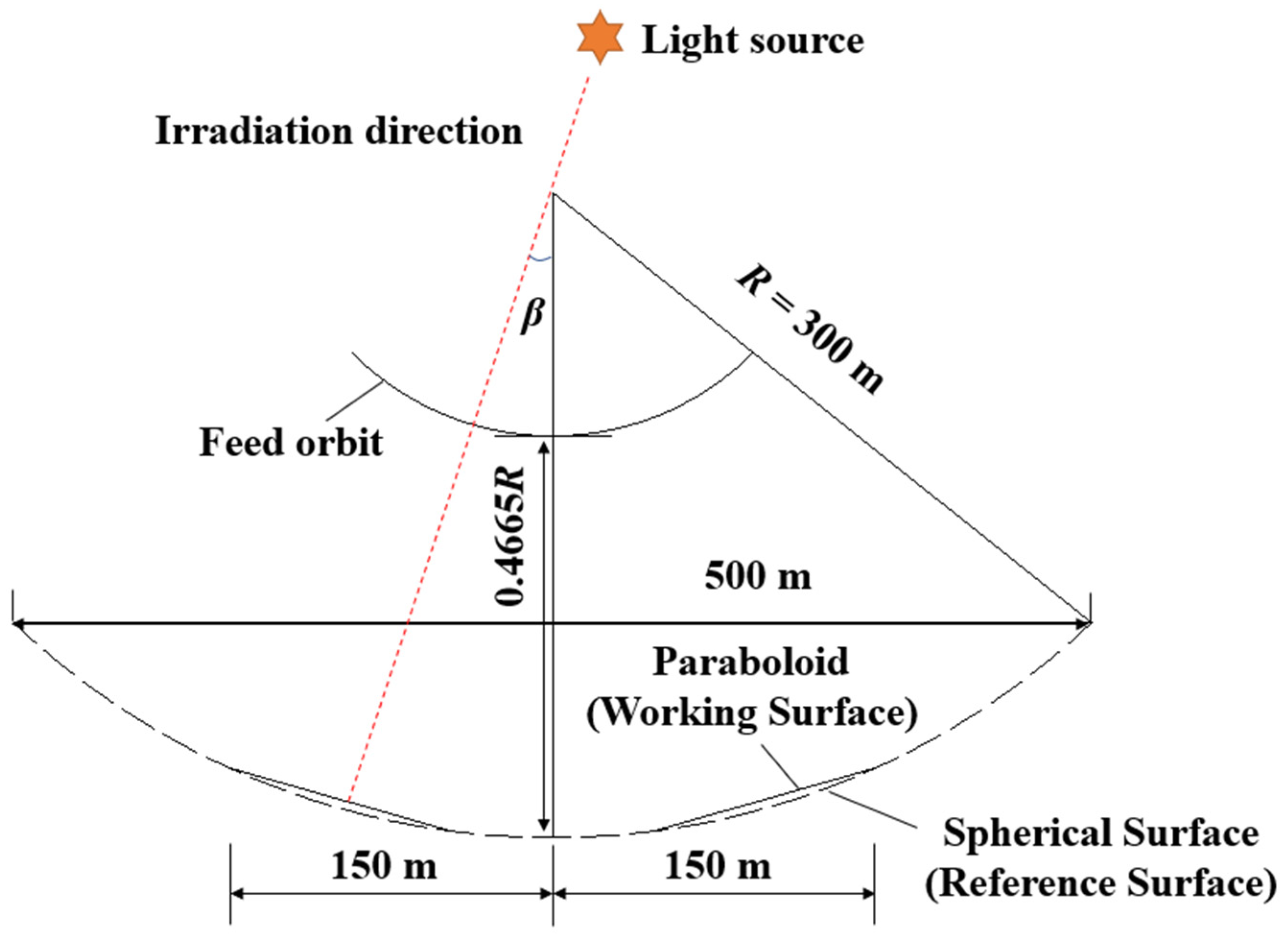
4. Form Analysis Results of the FAST Active Reflector Cable-Net Structure

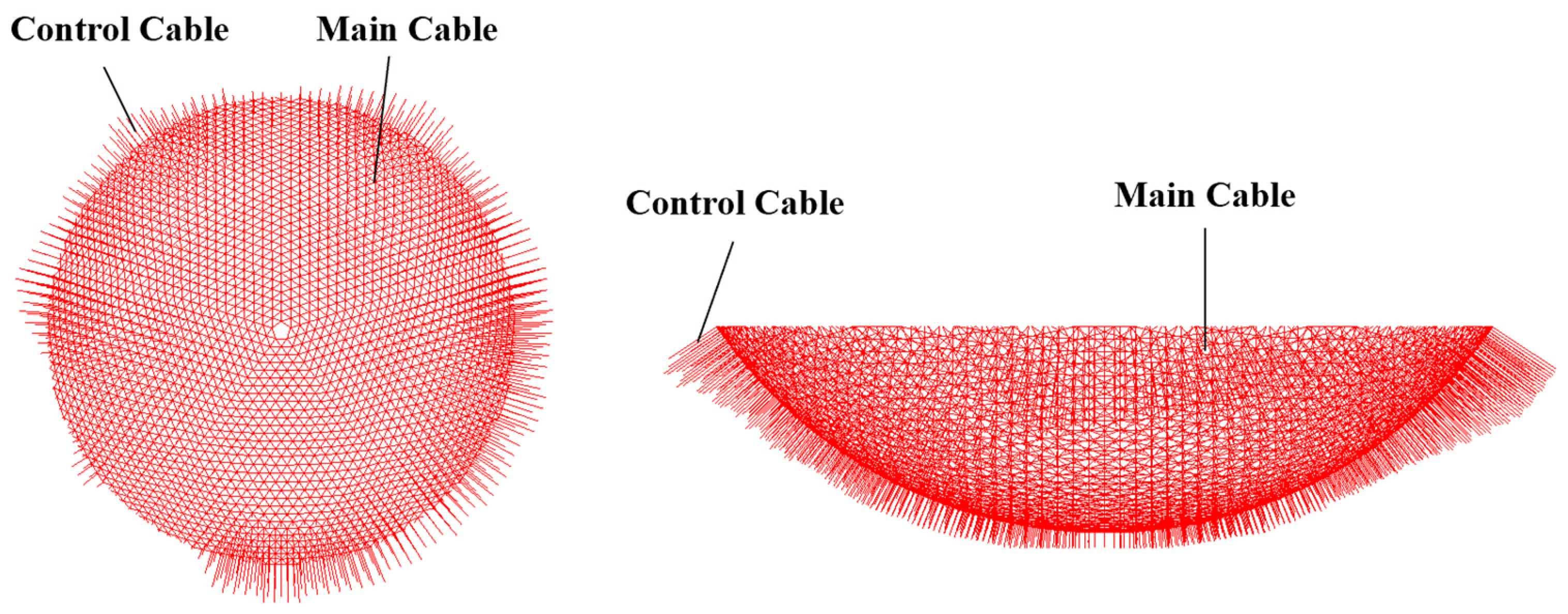
4.1. Numerical Model of the Cable-Net Structure

The cable-net structure model is established according to the overall scheme of the FAST active reflector, as shown in Figure 8. The model contains 2590 main cable nodes numbered J1 to J2590 in the ascending order of the Z coordinate. A total of 6980 main cables are numbered M1 to M6980 in the ascending order of the Z coordinate of the cable’s midpoint. A total of 2275 control cables are numbered C1 to C2275 according to the number of connected main cable nodes. The initial diameter of the main cables is 25 mm, while the initial control cable diameter is 10 mm. The elastic modulus E is 2 . 05   ×   10 5   MPa . The main cables applied a primary prestress of 400 MPa [35]. During the iterative process, the time step h of 4 . 0   ×   10 - 4   s is used, and ζ is set as 500. When the residual force |R| is lower than 0.001 N, the iterative computation is stopped.

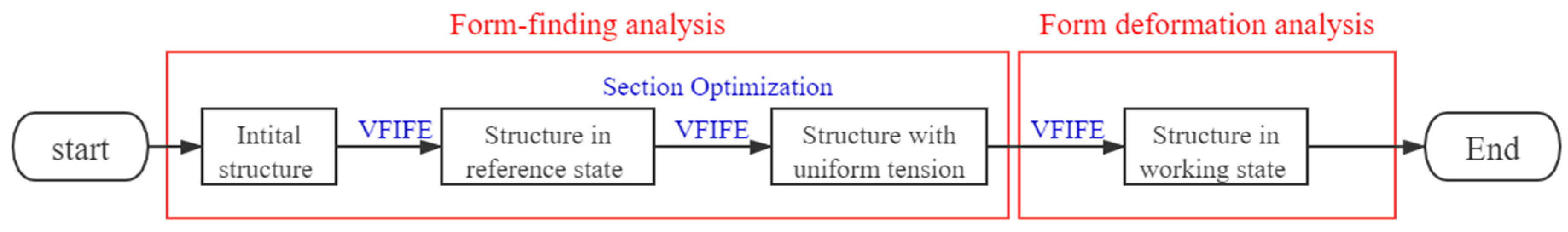
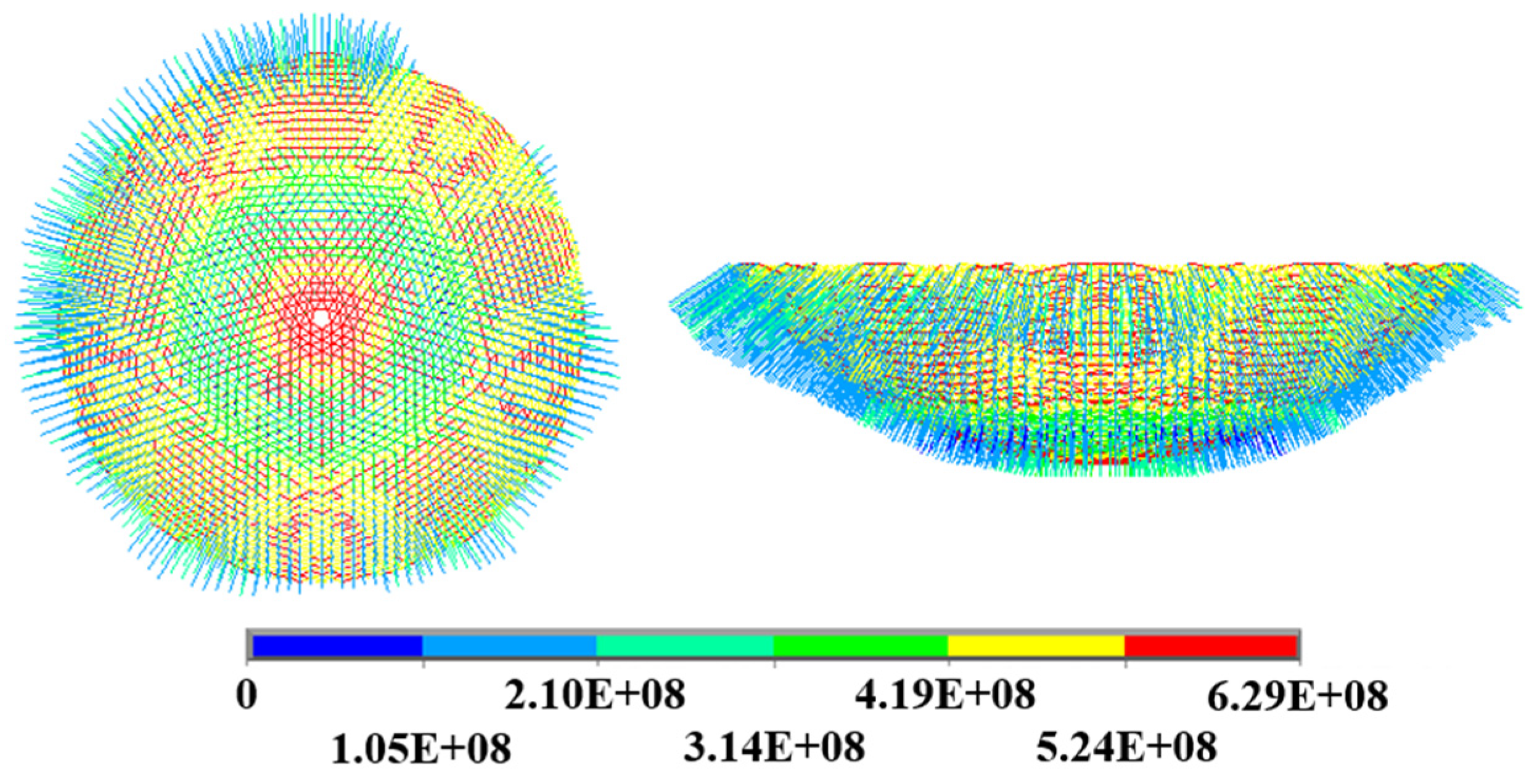
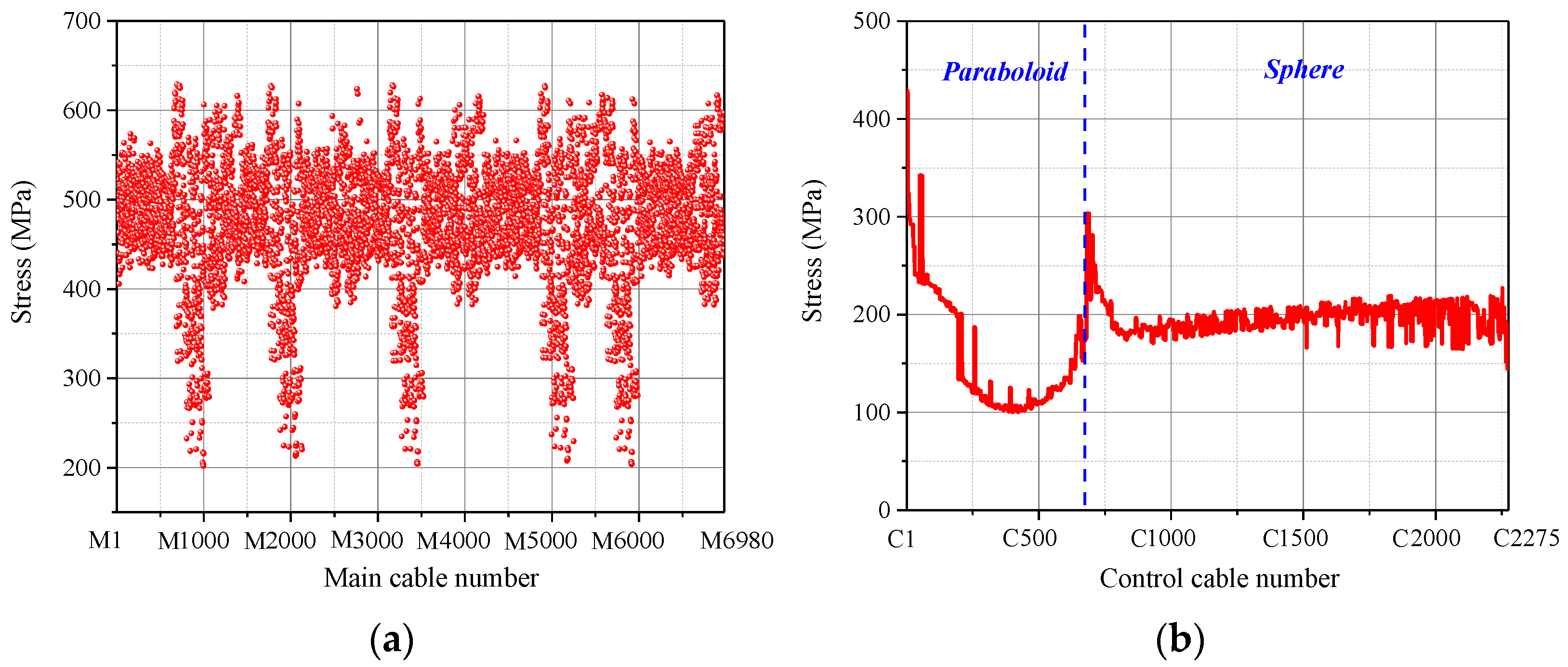
4.2. Form-Finding Analysis Results

Figure 9 is the stress nephogram of main cables before and after the section optimization. Before the section optimization, the stress of main cables ranged from 239.495 to 769.450 MPa, and the maximum stress to minimum stress ratio was 3.213. After the section optimization, the cable stress was aimed to be adjusted to the reference stress σ = 450 MPa, and the stress of main cables finally ranged from 465.251 to 576.734 MPa. The maximum stress to minimum stress ratio was 1.240, and the tension uniformity was greatly improved.
Figure 10 shows the stress distribution of the control cables. Since the control cables can adjust the force by changing the length, the stress level was relatively small. The stress of control cables finally ranged from 128.342 to 290.623 MPa after the section optimization.
After numerical verification, the FAST active reflector cable-net structures both before and after the section optimization satisfied the spherical surface of R = 300 m. Figure 11 shows the change in |R| over time and reflects that, during the iteration, the residual force |R| continuously decreased due to the alternating changes in the forced displacement and the actuator length until the accuracy requirements were met. The RMS error between the final form and the theoretical form was only 0.0097 mm. If iterations were continued, the RMS would be smaller. The length change of control cables, namely the length change of actuators, was also obtained, as shown in Figure 12. The maximum shortening was 0.00738 m, and the maximum elongation was 0.00859 m. The length change varied insignificantly.

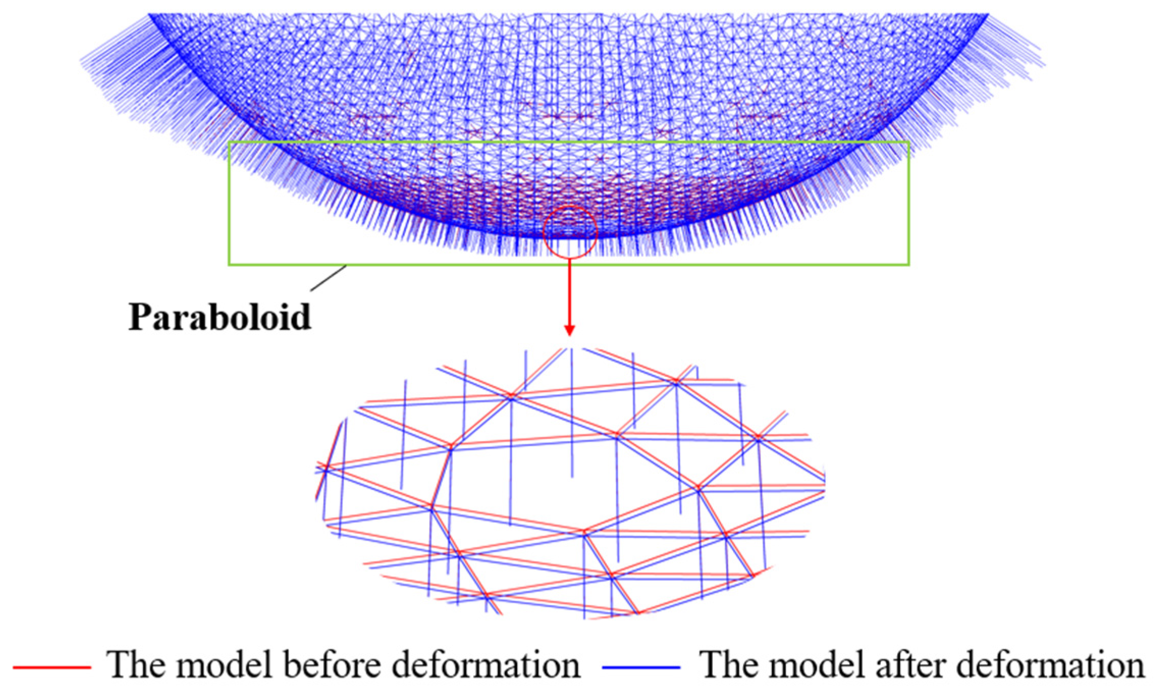
4.3. Form Deformation Analysis Results

A comparison of the FAST active reflector cable-net structure before and after the form deformation is shown in Figure 13. The green rectangular outline represents the designated paraboloid range. The reflector within this range was required to be adjusted from the reference spherical surface to the designated paraboloid, thus resulting in a relatively large deformation. As for the non-adjusting range, that is, the spherical range other than the designated paraboloid, the reflector had a relatively small deformation. Due to the large model size, the local model of the reflector center with the largest deformation is intercepted and scaled up in this paper.
After numerical verification, the FAST active reflector cable-net structure within the designated paraboloid range after the form deformation showed a paraboloid with a focal length of 0.4665R. The RMS error between the final form and the theoretical paraboloid was only 0.0133 mm, which met the accuracy requirements. Figure 14 shows the change in |R| over time. The equilibrium state after the form deformation was obtained. The above conclusions basically verify the feasibility of applying the VFIFE-based approach to the form analysis of the FAST active reflector cable-net structure.
In the form deformation, the stress level of the cable-net structure was obtained, and the stress nephogram is shown in Figure 15. Figure 16a shows the stress distribution diagram of the main cables. The stress of main cables ranged from 201.810 to 628.960 MPa. Figure 16b is the stress distribution diagram of the control cables. Since the control cables can adjust the force by changing the length, the stress level was relatively small. The control cables numbered C1 to C707 were within the target paraboloid range and were greatly affected by the changes in forced displacement and actuator length. Therefore, the stress varied greatly, ranging from 100.150 to 428.740 MPa. For the control cables numbered C708 to C2275, the variation range of stress was from 144.430 to 250.460 MPa. They were less affected by the changes in the forced displacement and the actuator length.
The length change of the control cables, namely the length change of the actuators, was also obtained from the form deformation analysis, as shown in Figure 17. The control cables numbered C1 to C707 were within the target paraboloid, and the length change of the actuators varied significantly. The control cables of C1 to C125 were shortened, and the maximum shortening was 0.4578 m. The control cables of C126 to C707 were extended, and the maximum elongation was 0.4729 m. The control cables numbered C708 to C2275 were outside the target paraboloid and were almost not affected by the forced displacement in the form analysis. The main cable nodes connected to these control cables were only adjusted with the formation of the target paraboloid. Therefore, the length change of the actuators was very small, and the maximum change was only 0.0068 m.

5. Conclusions

The form determination of cable-net structure directly affects the surface accuracy and mechanical performance of the active reflector. This paper offers an effective form analysis approach for this type of cable-net structure in detail. The main conclusions are as follows:
(1)
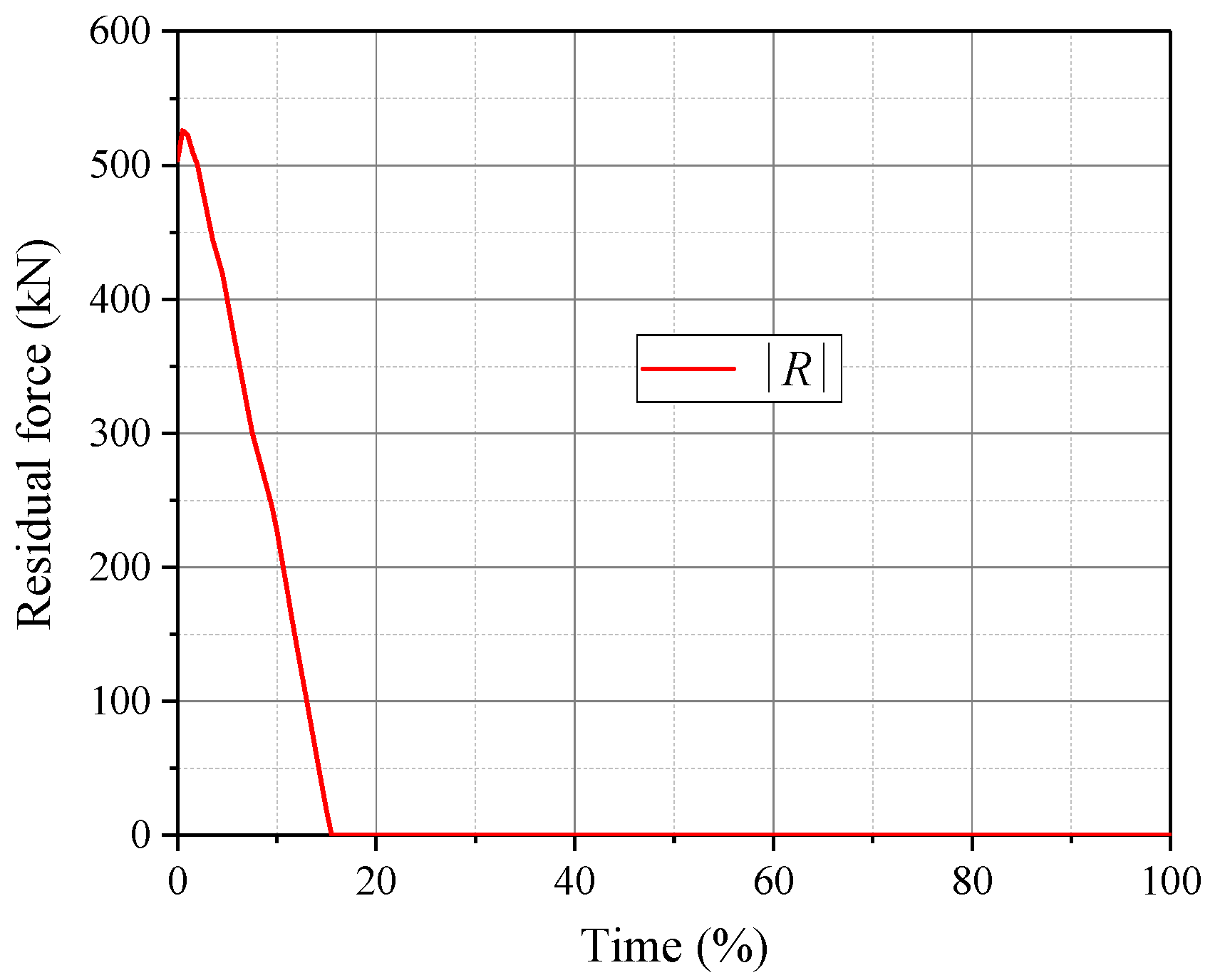
The basic principle and flow for solving the static equilibrium of the active reflector cable-net structure based on VFIFE were proposed. The core idea was to dissipate energy by applying virtual damping. Through the combined effect of forced displacement and actuator length changes, the cable-net structure can achieve the target form and the equilibrium state can be also obtained.
(2)
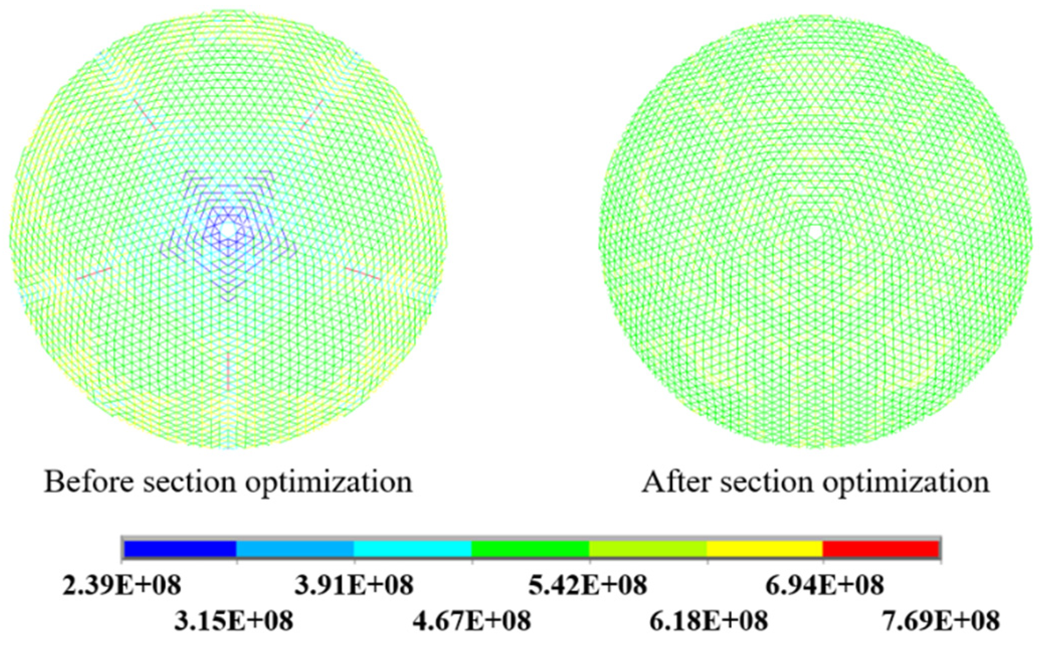
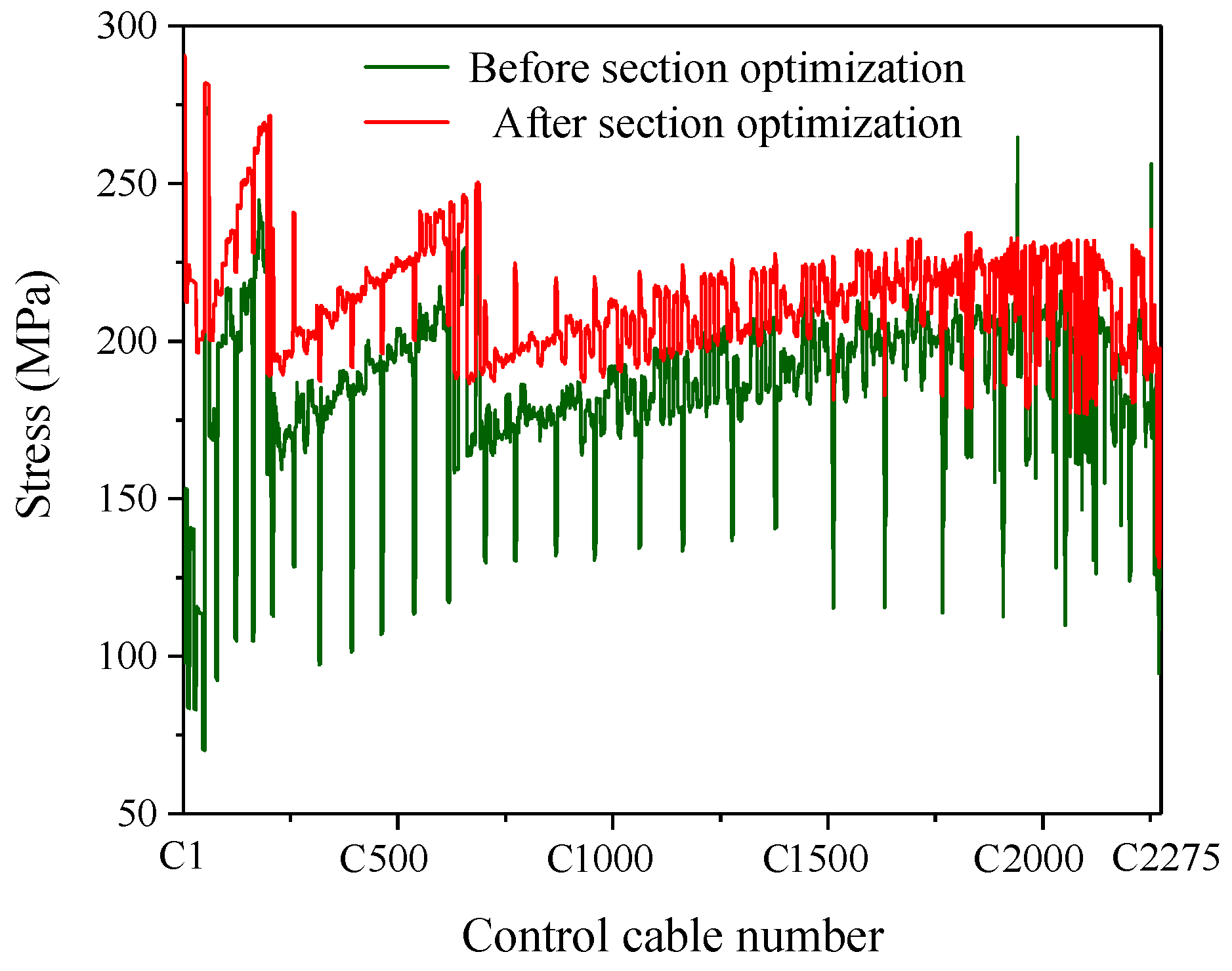
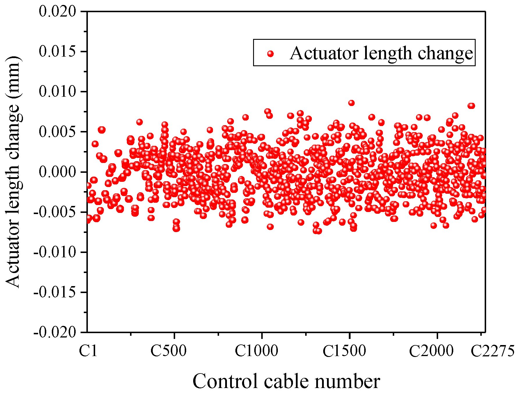
The approach proposed can help achieve a uniform cable tension design based on the idea of “equal-tension replacement” in the form-finding analysis. The RMS error between the final form and the theoretical form was only 0.0097 mm. In addition, the stress of both main cables and control stress was optimized to be uniform. While grasping the stress distribution of various cables through the form-finding analysis, the length change of the actuators was also obtained.
(3)
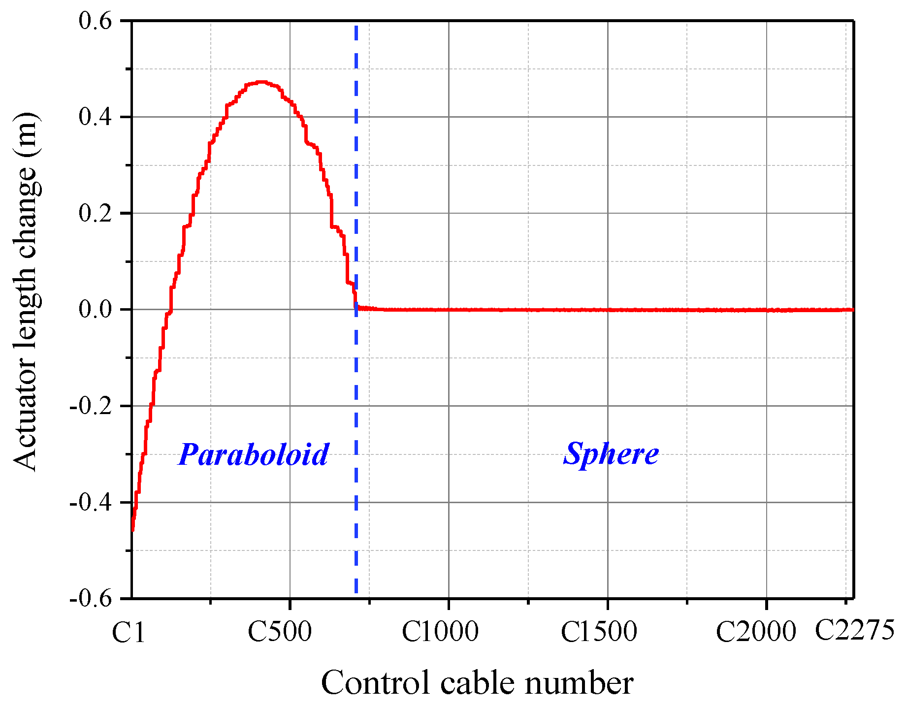
For the form deformation analysis, the change process from the reference state to the target working state was successfully simulated by the proposed approach. The final form obtained conforms to the designated working paraboloid. The RMS error between the final form and the theoretical paraboloid was only 0.0133 mm. Moreover, the stress of various cables and the length change of the actuators were also obtained. The above conclusions provide an important basis for the actual operation and the control optimization of the active reflector. This approach is also applicable to the form analysis of similar cable-net structures.

Author Contributions

Conceptualization, D.C.; methodology, Y.Z.; software, Y.Z. and K.Z.; validation, D.C.; resources, H.Q. and K.Z.; data curation, Y.Z.; writing—original draft preparation, D.C.; writing—review and editing, Y.Z.; supervision, H.Q. and H.W.; funding acquisition, H.Q. and H.W. All authors have read and agreed to the published version of the manuscript.

Funding

This research was funded by the National Natural Science Foundation of China, Grant Nos. 51678191 and 51808168, and the General Program of Natural Science Foundation of Shandong Province, Grant No. ZR2019MEE047.

Institutional Review Board Statement

Not applicable.

Informed Consent Statement

Not applicable.

Data Availability Statement

The data presented in this study are available on request from the corresponding author.

Conflicts of Interest

The authors declare no conflict of interest.

References

  1. Nan, R.; Peng, B. A Chinese concept for the 1 km2 radio telescope. Acta Astronaut. 2000, 46, 667–675. [Google Scholar] [CrossRef]
  2. Linkwitz, K.; Schek, H.J. Einige bemerkungenzur berechnung von vorgespannten seilnetzkon struktionen. Arch. Appl. Mech. 1974, 40, 145–158. [Google Scholar]
  3. Schek, H.J. The force density method for form finding and computation of general networks. Comput. Methods Appl. Mech. Eng. 1974, 3, 115–134. [Google Scholar] [CrossRef]
  4. Zhang, J.; Ohsaki, M. Adaptive force density method for form-finding problem of tensegrity structures. Int. J. Solids Struct. 2006, 43, 5658–5673. [Google Scholar] [CrossRef] [Green Version]
  5. Tanaka, H.; Shimozono, N.; Natori, M.C. A design method for cable network structures considering the flexibility of supporting structures. Trans. Jpn. Soc. Aeronaut. Space Sci. 2007, 50, 267–273. [Google Scholar] [CrossRef] [Green Version]
  6. Morterolle, S.; Maurin, B.; Quirant, J.; Dupuy, C. Numerical form-finding of geotensoid tension truss for mesh reflector. Acta Astronaut. 2012, 76, 154–163. [Google Scholar] [CrossRef] [Green Version]
  7. Maddio, P.D.; Meschini, A.; Sinatra, R.; Cammarata, A. An optimized form-finding method of an asymmetric large deployable reflector. Eng. Struct. 2019, 181, 27–34. [Google Scholar] [CrossRef]
  8. Yang, D.; Liu, J.; Zhang, Y.; Zhang, S. Optimal surface profile design of deployable mesh reflectors via a force density strategy. Acta Astronaut. 2016, 130, 137–146. [Google Scholar] [CrossRef]
  9. Thomson, M.W. The astromesh deployable reflector. In Proceedings of the IEEE Antennas and Propagation Society International Symposium, Carpinteria, CA, USA, 11–16 July 1999. [Google Scholar]
  10. Wang, X.; Cai, J.; Yang, R.; Feng, J. Form-finding of deployable mesh reflectors using dynamic relaxation method. Acta Astronaut. 2018, 151, 380–388. [Google Scholar] [CrossRef]
  11. Yang, G.; Yang, D.; Zhang, Y.; Du, J. Form-finding design of cable-mesh reflector antennas with minimal length configuration. Aerosp. Sci. Technol. 2017, 63, 9–17. [Google Scholar] [CrossRef]
  12. Day, A.S. An introduction to dynamic relaxation. Engineer 1965, 219, 218–221. [Google Scholar]
  13. Barnes, M.R. Form finding and analysis of tension structures by dynamic relaxation. Int. J. Space Struct. 1999, 14, 89–104. [Google Scholar] [CrossRef]
  14. Rezaiee-Pajand, M.; Arabi, E.; Masoodi, A.R. Nonlinear analysis of FG-sandwich plates and shells. Aerosp. Sci. Technol. 2019, 87, 178–189. [Google Scholar] [CrossRef]
  15. Ma, X.; Song, Y.; Li, Z.; Li, T.; Wang, Z.; Deng, H. Mesh reflector antennas: Form-finding analysis review. In Proceedings of the 54th AIAA/ASME/ASCE/AHS/ASC Structures, Structural Dynamics, and Materials Conference, Boston, MA, USA, 8–11 April 2013. [Google Scholar]
  16. Li, T.; Jiang, J.; Deng, H.; Lin, Z.; Wang, Z. Form-finding methods for deployable mesh reflector antennas. Chin. J. Aeronaut. 2013, 26, 1276–1282. [Google Scholar] [CrossRef] [Green Version]
  17. Yuan, S.; Yang, B. The fixed nodal position method for form finding of high-precision lightweight truss structures. Int. J. Solids Struct. 2019, 161, 82–95. [Google Scholar] [CrossRef]
  18. Shi, H.; Yuan, S.; Yang, B. New methodology of surface mesh geometry design for deployable mesh reflectors. J. Spacecr. Rockets 2018, 55, 266–281. [Google Scholar] [CrossRef]
  19. Yuan, S.; Yang, B.; Fang, H. The projecting surface method for improvement of surface accuracy of large deployable mesh reflectors. Acta Astronaut. 2018, 151, 678–690. [Google Scholar] [CrossRef]
  20. Li, P.; Liu, C.; Tian, Q.; Hu, H.; Song, Y. Dynamics of a deployable mesh reflector of satellite antenna: Form-finding and modal analysis. J. Comput. Nonlinear Dyn. 2016, 11, 041017. [Google Scholar] [CrossRef]
  21. Nie, R.; He, B.; Zhang, L.; Fang, Y. Deployment analysis for space cable net structures with varying topologies and parameters. Aerosp. Sci. Technol. 2017, 68, 1–10. [Google Scholar] [CrossRef]
  22. Nie, R.; He, B.; Hodges, D.H.; Ma, X. Integrated form finding method for mesh reflector antennas considering the flexible truss and hinges. Aerosp. Sci. Technol. 2019, 84, 926–937. [Google Scholar] [CrossRef]
  23. Ting, E.C.; Shi, C.; Wang, Y.K. Fundamentals of a vector form intrinsic finite element: Part I. Basic procedure and a planar frame element. J. Mech. 2004, 20, 113–122. [Google Scholar] [CrossRef]
  24. Ting, E.C.; Shi, C.; Wang, Y.K. Fundamentals of a vector form intrinsic finite element: Part II. Plane solid element. J. Mech. 2004, 20, 123–132. [Google Scholar] [CrossRef]
  25. Shi, C.; Wang, Y.K.; Ting, E.C. Fundamentals of a vector form intrinsic finite element: Part III. Convected material frame and examples. J. Mech. 2004, 20, 133–143. [Google Scholar] [CrossRef]
  26. Wu, T.Y.; Wang, C.Y.; Chuang, C.C.; Ting, E.C. Motion analysis of 3D membrane structures by a vector form intrinsic finite element. J. Chin. Inst. Eng. 2007, 30, 961–976. [Google Scholar] [CrossRef]
  27. Wu, T.Y.; Ting, E.C. Large deflection analysis of 3D membrane structures by a 4-node quadrilateral intrinsic element. Thin-Walled Struct. 2008, 46, 261–275. [Google Scholar] [CrossRef]
  28. Hou, X.; Fang, Z.; Zhang, X. Static contact analysis of spiral bevel gear based on modified VFIFE (vector form intrinsic finite element) method. Appl. Math. Model. 2018, 60, 192–207. [Google Scholar] [CrossRef]
  29. Lien, K.H.; Chiou, Y.J.; Wang, R.Z.; Hsiao, P.A. Vector form intrinsic finite element analysis of nonlinear behavior of steel structures exposed to fire. Eng. Struct. 2010, 32, 80–92. [Google Scholar] [CrossRef]
  30. Lien, K.H.; Chiou, Y.J.; Wang, R.Z.; Hsiao, P.A. Nonlinear behavior of steel structures considering the cooling phase of a fire. J. Constr. Steel Res. 2009, 65, 1776–1786. [Google Scholar] [CrossRef]
  31. Duan, Y.F.; Wang, S.M.; Wang, R.Z.; Wang, C.Y.; Ting, E.C. Vector form intrinsic finite element based approach to simulate crack propagation. J. Mech. 2017, 33, 797–812. [Google Scholar] [CrossRef]
  32. Xu, L.; Lin, M. Numerical study on critical axial forces of upheaval buckling for initially stressed submarine pipelines on uneven seabed. Ocean Eng. 2017, 145, 344–358. [Google Scholar] [CrossRef] [Green Version]
  33. Xu, L.; Lin, M. On the critical axial forces of upheaval buckling for imperfect submarine pipelines. Eng. Struct. 2017, 147, 692–704. [Google Scholar] [CrossRef] [Green Version]
  34. China Academy of Building Research. Technical Specification for Cable Structures; China Academy of Building Research: Beijing, China, 2012; JGJ 257-2012. [Google Scholar]
  35. Qian, H. Theoretical and Experimental Research on Supporting Structure of FAST Reflector. Ph.D. Dissertation, Harbin Institute of Technology, Harbin, China, 2007. [Google Scholar]
Figure 1. Overall cable-net structure of the FAST: (a) numerical model; (b) local detailed cable-net structure.
Aerospace 08 00269 g001
Figure 2. Relationship between the reference state and working state.
Aerospace 08 00269 g002
Figure 3. Discretization of the active reflector cable-net structure.
Aerospace 08 00269 g003
Figure 4. Schematic diagram of path elements.
Aerospace 08 00269 g004
Figure 5. Calculation flow of VFIFE.
Aerospace 08 00269 g005
Figure 6. Schematic representation of iterative steps.
Aerospace 08 00269 g006
Figure 7. Calculation flow of the form analysis.
Aerospace 08 00269 g007
Figure 8. Numerical model of the FAST active reflector cable-net structure.
Aerospace 08 00269 g008
Figure 9. Stress nephogram of main cables.
Aerospace 08 00269 g009
Figure 10. The stress distribution of control cables.
Aerospace 08 00269 g010
Figure 11. Change of residual force |R| over time.
Aerospace 08 00269 g011
Figure 12. Length change of actuators.
Aerospace 08 00269 g012
Figure 13. Comparison between two structures before and after deformation.
Aerospace 08 00269 g013
Figure 14. Residual force |R| changing curve.
Aerospace 08 00269 g014
Figure 15. Stress diagram of the cable-net structure after the form deformation.
Aerospace 08 00269 g015
Figure 16. Stress distribution of cables: (a) stress distribution of main cables; (b) stress distribution of control cables.
Aerospace 08 00269 g016
Figure 17. Actuator length changes in form deformation analysis.
Aerospace 08 00269 g017
Publisher’s Note: MDPI stays neutral with regard to jurisdictional claims in published maps and institutional affiliations.

