Article

Stellar Angle-Aided Pulse Phase Estimation and Its Navigation Application

1
College of Aerospace Science and Engineering, National University of Defense Technology, Changsha 410073, China
2
College of Aviation Operations and Services, Aviation University of Air Force, Changchun 130000, China
*
Author to whom correspondence should be addressed.
Aerospace 2021, 8(9), 240; https://doi.org/10.3390/aerospace8090240
Submission received: 14 July 2021 / Revised: 20 August 2021 / Accepted: 27 August 2021 / Published: 31 August 2021

Abstract

:
X-ray pulsar-based navigation (XNAV) is a promising autonomous navigation method, and the pulse phase is the basic measurement of XNAV. However, the current methods for estimating the pulse phase for orbiting spacecraft have a high computational cost. This paper proposes a stellar angle measurement-aided pulse phase estimation method for high Earth orbit (HEO) spacecraft, with the aim of reducing the computational cost of pulse phase estimation in XNAV. In this pulse phase estimation method, the effect caused by the orbital motion of the spacecraft is roughly removed by stellar angle measurement. Furthermore, a deeply integrated navigation method using the X-ray pulsar and the stellar angle is proposed. The performances of the stellar angle measurement-aided pulse phase estimation method and the integrated navigation method were verified by simulation. The simulation results show that the proposed pulse phase estimation method can handle the signals of millisecond pulsars and achieve pulse phase estimation with lower computational cost than the current methods. In addition, for HEO spacecraft, the position error of the proposed integrated navigation method is lower than that of the stellar angle navigation method.

1. Introduction

Due to the significant increase in the number of spacecraft in recent years, the burden of ground-based tracking systems has also increased, reducing the survivability of spacecraft [1]. Thus, autonomous navigation is necessary [2]. For Earth-orbit spacecraft, the Global Navigation Satellite System (GNSS) is employed for autonomous navigation and has excellent performance. However, the signals of GNSS are subject to interference, which significantly affects the survivability of spacecraft [3]. Moreover, because the intensity of the GNSS signals decays with the increase in the client spacecraft’s orbital altitude, the navigation performance of GNSS is not well enough for spacecraft at orbits higher than 3000 km [4]. Thus, developing an autonomous navigation technique with anti-interference capability for these spacecraft is necessary. Furthermore, due to the increase in the number of spacecraft launches, the required improvement in navigation systems can be understood from the perspective of the new generation of instrumentation for Space Traffic Management (STM) [5,6,7].
XNAV is a promising autonomous navigation technique that has anti-interference characteristics and can be applied in near-Earth and deep space. In this paper, we focus on XNAV for near-Earth spacecraft, which are within the gravitational field of the Earth. Pulsars can provide radiation with stable periodicities because they spin with highly stable periodicities [8]. Although pulsars can provide radiation ranging from optical to gamma frequencies, Emadzadeh and Speyer recommended X-ray radiation for navigation because it can be utilized by small-sized detectors [9]. Since being introduced by Chester and Butman [10], XNAV has experienced significant growth [11,12]. Moreover, flight experiments have been performed. In 2018, the United States announced their SEXTANT (Station Explorer for X-ray Timing and Navigation Technology) flight experiments with a position error less than 10 km [13]. In addition, China also verified the feasibility of XNAV, in principle, using real data from TG-2 (Tiangong-2) Spacelab and the Insight-HXMT (Insight-Hard X-ray Modulation Telescope) [14,15].
The difference between the pulse Time of Arrival (TOA) predicted at the SSB (Solar System Barycenter) with that estimated at the spacecraft can reflect the position of the spacecraft in the direction of pulsar [8]. However, because the signal of the pulsar is very weak, the spacecraft cannot record a continuous pulsed signal but a series of photon TOAs. Thus, one key technique of XNAV is to estimate the pulse TOA using the recorded photon TOAs. For a spacecraft that is stationary or performs a uniform linear motion towards the pulsar, two types of methods are effective for estimating the pulse TOA, namely, the epoch folding method [16] and the maximum likelihood estimator (MLE) method [17]. The epoch folding method compares the template with the empirical profile recovered from photon TOAs and estimates the pulse TOA [16]. Based on epoch folding, a large number of methods for pulse phase estimation have been proposed in recent years. In the weighted average method, the final accurate pulse phase is estimated from the generated estimations, which are derived from a universal set of photon TOAs [18]. Rao et al. proposed an FrFT-based GCC method, which can estimate the pulse phase with higher accuracy than that of the GCC method [19]. In addition, methods have been proposed to reduce the computational cost of the epoch method [20,21]. The MLE method is also well developed. The photon TOAs recorded by the spacecraft follow the non-homogeneous Poisson process [17]. Thus, the MLE method is used to derive a likelihood function and can estimate the pulse TOA by maximizing the likelihood function.
However, in practice, spacecraft perform orbital motions, causing the pulsar signal to have a time-varying Doppler frequency. The velocity and position of the spacecraft are unknown in an autonomous navigation task; thus, it is difficult to reduce the impact of the introduced Doppler frequency. The epoch folding and MLE methods fail when used in this situation. To solve this problem, a phase tracking algorithm was proposed by Golshan and Sheikh [22]. This method divides the pulsar observation period into several intervals within each of which the spacecraft can be assumed to perform a linear uniform motion. Therefore, the Doppler frequency can be assumed to be a constant and can be tracked by a Digital Phase-Locked Loop (DPLL). The performance of the phase tracking method depends on the duration of the interval. In order to assume the spacecraft performs a uniform linear motion within an interval, the interval’s duration should be sufficiently short. However, when the duration is shorter than a certain threshold, the pulse phase method cannot obtain a reliable result [23]. The flux of the pulsar determines the threshold. For a faint millisecond pulsar, PSR B1821-24, the threshold is about 100 s [24]. However, the assumption that an Earth-orbiting spacecraft performs a uniform linear motion within 100 s is usually violated. Consequently, the phase tracking method fails to handle the signal of a faint millisecond pulsar.
To overcome the problem of the phase tracking method, a phase estimation method with the aid of the orbital dynamics of the spacecraft was proposed by Wang and Zheng [25,26]. In the remainder of this paper, this method is referred to as the linearized method. The linearized method derives a pulse phase propagation model. In this model, the pulse phase consists of a polynomial term and a predicted term. The linearized method estimates the pulse phase by estimating the parameters of the polynomial term. Because the observation period is not divided into intervals, the linearized method is appropriate for handling the signal of millisecond pulsars. In addition, the Doppler frequency and pulse phase can be simultaneously estimated by a maximum likelihood estimator [27]. Moreover, Xue et al. proposed to estimate the Doppler frequency and pulse phase using the H-test and the fast maximum likelihood method, respectively, thereby partly reducing the computational cost [28]. However, an accurate pulse phase estimation result still needs a large number of photons, which leads to high computational costs. Thus, the above phase estimation methods lead to a rigorous demand for onboard computers.
In addition to the orbit dynamics of spacecraft, the information from other measurements can be used to estimate the pulse TOA. A deeply integrated navigation method that utilizes starlight Doppler measurement was proposed by Wang et al. [24]. Using the starlight Doppler measurement, the effect of orbital motion is roughly removed. In addition, Liu et al. proposed a deeply integrated navigation method that utilizes direction, velocity, and distance measurements [29]. This navigation method uses direction and velocity measurements to remove the effect of orbital motion. However, the spectrometer, the equipment which measures the starlight Doppler, remains underdeveloped, and the measurement accuracies used in the above papers are higher than the current status.
Compared with the spectrometer, the star tracker and the horizon sensor, which can be used to derive the stellar angle measurement, are well developed [30]. Thus, we proposed a deeply integrated navigation method using the X-ray pulsar and stellar angle for high-Earth orbit (HEO) spacecraft.
The integrated navigation method using the X-ray pulsar and stellar angle has been widely studied for Earth-orbit, Mars-orbit, and Jupiter-orbit spacecraft [31,32,33]. In the classical integrated navigation methods using the X-ray pulsar and stellar angle, the pulse TOA is estimated independently, and the pulse TOA and stellar angle measurement are fused to estimate the state of the spacecraft. In contrast, the proposed navigation method employs the stellar angle measurement to estimate the pulse TOA, and thus the integration is more sophisticated than the classical integrated navigation method. We derived a stellar angle-aided pulse propagation model which roughly removes the effect of the orbital motion of the spacecraft. Thus, the pulse phase can be estimated by the epoch folding method. The epoch folding method is used because it is more computationally efficient than MLE. Then, the position of the spacecraft is estimated by the pulse TOA. Compared with the current method for estimating the pulse TOA for orbiting spacecraft, the proposed method can greatly reduce the computational burden. In addition, the proposed integrated navigation approach can also be used for Lunar/Mars satellite missions. Limited by its technical level, the current X-ray detector is extremely large; thus, the proposed method is only applicable to large spacecraft. In the future, with the improvement in detection efficiency, this method can hopefully be applied to nano satellites.
This paper is organized as follows. In Section 2, we describe the overall design of the deeply integrated navigation system. We review the relevant works of pulse phase estimation in Section 3. Section 4 outlines the stellar angle measurement-aided pulse phase estimation method. In Section 5, simulations are performed to verify the performance of the stellar angle measurement-aided pulse phase estimation method and integrated navigation method. Finally, the conclusions are given in Section 6.

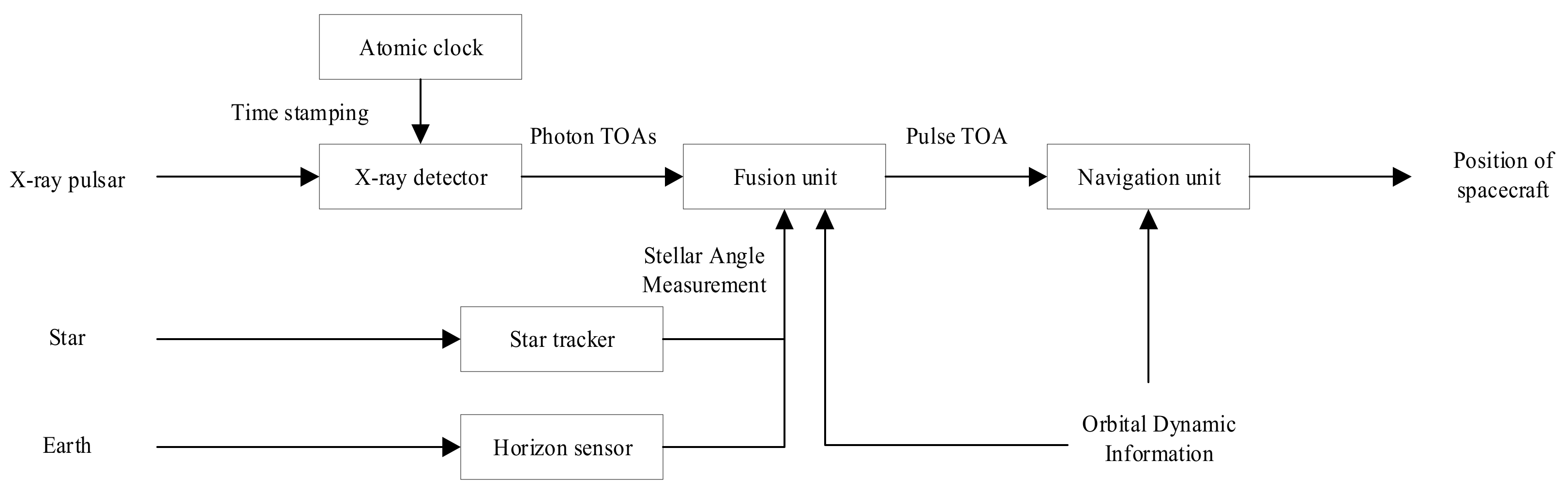
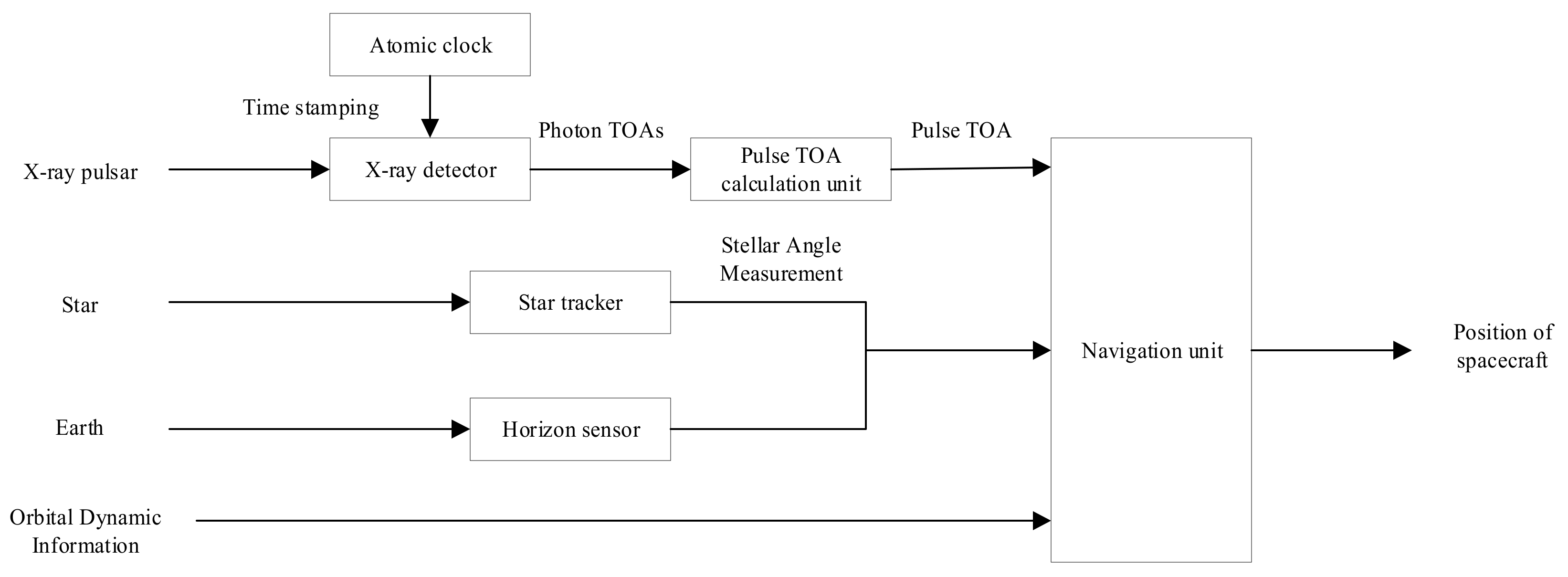
2. Overall Design of the Deeply Integrated Navigation System

The composition of the proposed deeply integrated navigation system using the X-ray pulsar and stellar angle is shown in Figure 1. It can be seen that the integrated navigation system comprises five units: (1) X-ray detectors, which detect the X-ray radiation signal of the pulsars; (2) atomic clocks, which provide a timestamp for the recorded photons; (3) star trackers and horizon sensors, which provide the stellar angle measurement; (4) a fusion unit, which provides the pulse TOA by processing the photon TOAs, the stellar angle measurement, and the orbital dynamics information of the spacecraft; (5) a navigation unit, which estimates the position of the spacecraft by processing the orbital dynamics information of the spacecraft and the pulse TOA.
As shown in Figure 2, the pulse TOA is estimated independently in the current integrated navigation system. The position of the spacecraft is estimated in the navigation unit by processing the pulse TOA, the stellar angle, and the orbital dynamics information of the spacecraft.
Compared with the current integrated navigation system, the navigation unit in the proposed deeply integrated navigation system only needs to process the orbital dynamics information and the pulse TOA, which has been previously well studied. According to Ref. [34], the navigation unit is shown in Figure 3. In the navigation unit, the orbital dynamics information and the pulse TOA are processed using a Unscented Kalman Filter (UKF) and the estimated position of the spacecraft is obtained [34].
In the proposed navigation method, the fusion unit is the key unit. Thus, in the following sections, the design of the fusion unit is introduced.

3. Relevant Works of Pulse Phase Estimation

3.1. Principle of Pulse Phase Estimation

The recorded pulsar photons obey a non-homogeneous Poisson process with a periodic rate function. λ ( t ) is the rate function and is of the form [35]:
λ ( t ) = β + α h ( ϕ det ( t ) )
The parameters α and β represent the average signal and total background count rates in units of counts per second, respectively. ϕ det ( t ) represents the detected pulsar signal phase and h ( ) is the normalized profile function of the pulsar.
Considering the orbital motion of the spacecraft, ϕ det ( t ) can be modelled as [24]:
ϕ det ( t ) = ϕ 0 + f s ( t t 0 ) + f s c t 0 t n v ( τ ) d τ
where ϕ 0 is the initial phase at t 0 , c represents the speed of light, f s represents the frequency of the pulsar, n represents the direction vector of the pulsar, and v represents the velocity of the spacecraft.

3.2. Epoch Folding Method

The epoch folding method is used to recover the pulse profile from the recorded photons and is a widely applied method. Assuming that the observation period lasts T o b s , which consists of N P pulsar periods P , we have T o b s N P P . Furthermore, P can be divided into N b bins with a bin size of T b [16]. The procedure of epoch folding is described below. First, we fold back the recorded photons into the first period. Then, we count the number of photons collected in each bin. Finally, the empirical profile is recovered by normalizing the counts of the computed photons.
The empirical profile λ ˜ ( T i ) in the ith bin i [ 1 , N b ] can be described by [16]:
λ ˜ ( T i ) = 1 N p T b j = 1 N p c j ( T i )
where c j is the number of photons in the ith bin folded by the jth period, and T i is the center of the ith bin.
After recovering the empirical profile, we can estimate the pulse phase by comparing the empirical profile and the template. The representative methods for epoch folding are the nonlinear least square method, the cross-correlation method, and the fast near-maximum likelihood estimator [36,37]. The epoch folding method is effective under the premise that the pulse period is constant. However, for an orbiting spacecraft, the recorded pulse period varies with time and the epoch folding cannot be directly used.

4. Stellar Angle Measurement-Aided Pulse Phase Estimation Method

In this section, we take the Earth-orbit spacecraft as an example and show the estimation of the position of the spacecraft using stellar angle measurements and the derivation of the stellar angle measurement-aided pulse phase estimation method.

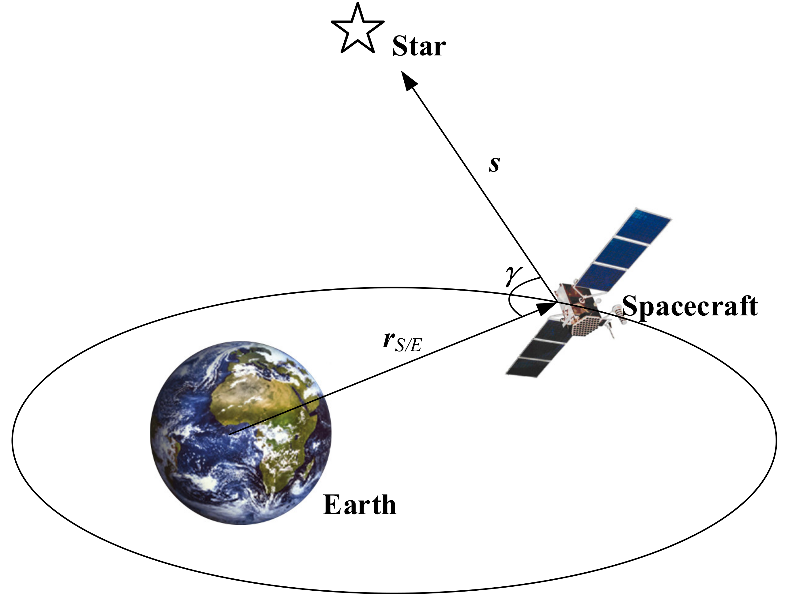
4.1. Position Estimation by Stellar Angle Measurement

As shown in Figure 4, the stellar angle measurement model has the form [31]:
π γ = arccos ( r S / E s r S / E ) + v α
where s represents the direction vector of the reference star, v α is a zero-mean Gaussian measurement noise, and r ^ S / E is the position of the spacecraft relative to Earth. The value of r ^ S / E can be estimated using the stellar angle measurement and the orbital dynamics information of the spacecraft [38].

4.2. Stellar Angle Measurement-Aided Phase Propagation Model

For a spacecraft in an Earth-orbit, we have [24]:
t 0 t n v ( τ ) d τ = n [ r ˜ S / E ( t ) r ˜ S / E ( t 0 ) ] + n [ r ˜ E ( t ) r ˜ E ( t 0 ) ]
where r ˜ E is the position of the Earth and can be obtained from DE405 or DE421. Because r ˜ E is known, our task is to solve the first term on the right-hand side of Equation (5).
The true r ˜ S / E is unknown, and the estimated r ^ S / E is substituted into Equation (5), giving:
n [ r ˜ S / E ( t ) r ˜ S / E ( t 0 ) ] n [ r ^ S / E ( t ) r ^ S / E ( t 0 ) ]
Substituting Equations (5) and (6) into Equation (2), yielding:
ϕ det ( t ) = ϕ 0 + f s ( t t 0 ) + f s c n [ r ^ S / E ( t ) r ^ S / E ( t 0 ) ] + f s c n [ r ˜ E ( t ) r ˜ E ( t 0 ) ]
Equation (7) is the stellar angle measurement-aided phase propagation model based on the assumption that the difference between each recorded photon TOA is close to the sampling period of the stellar angle measurement. However, the difference between each recorded photon TOA is considerably shorter than the sampling period of the stellar angle. Thus, if Equation (7) is used to estimate the pulse phase, numerous photons are not applied, thus significantly reducing the accuracy of the pulse phase estimation. To employ all of the photon TOAs, we use a cubic spline interpolation to obtain the estimated position r p of the spacecraft at photon TOAs between the sampling period of the stellar angle. If the photon TOA t p ( j T s , ( j + 1 ) T s ) , r p can be estimated as:
r p = S j ( t p , r ^ S / E ( j T s ) , r ^ S / E ( ( j + 1 ) T s ) )
where S j is the cubic polynomial in ( j T s , ( j + 1 ) T s ) .
Then, the stellar angle measurement-aided phase propagation model is:
ϕ det ( t ) = ϕ 0 + f s ( t t 0 ) + f s c n [ r ˜ E ( t ) r ˜ E ( t 0 ) ] + ϕ s t e l l a r   a n g l e ( t )
where:
ϕ s t e l l a r   a n g l e ( t ) = f s c n [ r ^ S / E ( t ) r ^ S / E ( t 0 ) ] ,       t = j T s f s c n [ r p ( t ) r ^ S / E ( t 0 ) ] ,       t ( j T s , ( j + 1 ) T s ) , j = 0 , 1 , 2 , , N 1
We fold the photon TOAs to the last pulse period to ensure the real-time navigation performance, yielding:
ϕ det ( t ) = ϕ e n d + f s ( t t e n d ) + f s c n [ r ˜ E ( t ) r ˜ E ( t e n d ) ] + ϕ s t e l l a r   a n g l e e n d ( t )
where:
ϕ s t e l l a r   a n g l e e n d = f s c n [ r ^ S / E ( t ) r ^ S / E ( t e n d ) ] ,       t = j T s f s c n [ r p ( t ) r ^ S / E ( t e n d ) ] ,       t ( j T s , ( j + 1 ) T s ) , j = 0 , 1 , 2 , , N 1
In Equation (11), the orbital effect is approximately removed by ϕ s t e l l a r   a n g l e e n d . Thus, the pulse phase ϕ e n d can be estimated by the epoch folding method.

4.3. Summary of the Stellar Angle Measurement-Aided Pulse Phase Estimation Method

The procedure of the proposed stellar angle measurement-aided pulse phase estimation method is described below:
Step 1 Estimate the position of the spacecraft by the stellar angle measurement and orbital dynamics information of the spacecraft;
Step 2 Use Equation (11) to remove the orbit effect of the spacecraft in the recorded photon TOAs;
Step 3 Estimate the pulse phase ϕ e n d in Equation (11) by the epoch folding method.

4.4. Accuracy of the Stellar Angle Measurement-Aided Phase Estimation

As shown in Equation (11), the accuracy of ϕ det ( t ) is depends on the accuracy of ϕ s t e l l a r   a n g l e e n d ( t ) . We define ϕ o r b i t ( t ) = n [ r ˜ S / E ( t ) r ˜ S / E ( t 0 ) ] , and the estimation error of ϕ s t e l l a r   a n g l e e n d ( t ) has the form:
Δ ϕ s t e l l a r   a n g l e e n d ( t ) = ϕ o r b i t ( t ) ϕ s t e l l a r   a n g l e e n d ( t ) = f s c n ( [ r ˜ S / E ( t ) r ˜ S / E ( t e n d ) ] [ r ^ S / E ( t ) r ^ S / E ( t e n d ) ] ) ,       t = j T s f s c n ( [ r ˜ S / E ( t ) r ˜ S / E ( t e n d ) ] [ r p ( t ) r ^ S / E ( t e n d ) ] ) ,       t j T s , ( j + 1 ) T s = f s c n [ Δ r ^ S / E ( t ) Δ r ^ S / E ( t e n d ) ] ,       t = j T s f s c n [ Δ r p ( t ) Δ r ^ S / E ( t e n d ) ] ,       t j T s , ( j + 1 ) T s = f s c n Δ d ^ ,       t = j T s f s c n Δ d ^ p ,       t j T s , ( j + 1 ) T s
where n Δ d ^ and n Δ d ^ p are the displacement of the spacecraft in the pulsar direction. It is obvious that the estimated accuracy of n Δ d ^ and n Δ d ^ p determines the accuracy of ϕ s t e l l a r e n d ( t ) and ϕ det ( t ) . Thus, the performance of the stellar angle measurement-aided pulse phase estimation depends on the estimated accuracy of the displacement of the spacecraft in the direction of the pulsar.

5. Simulations

We investigated three Earth-orbit spacecraft with the orbital elements shown in Table 1 [24]. We take the PSR B1821-24 pulsar as the observed pulsar, for which the simulation parameters are listed in Table 2 [39]. The template profile of this pulsar is given in Figure 5. We use DE405 to predict the position of Earth. The pulse phase ϕ e n d is estimated by the nonlinear least square method using the epoch folding method.
The data of navigation stars are shown in Table 3 [24]. We define the evaluation criterion of the estimation performance as the Root Mean Square (RMS) error of pulse phase ϕ e n d from 1000 Monte Carlo trials.
First, we analyze the performance of the proposed stellar angle measurement-aided pulse phase estimation method. Because the accuracy of the horizon sensors is significantly lower than that of star trackers [30], the accuracy of the stellar angle is mainly determined by the accuracy of the horizon sensors. We assume that the accuracy of the horizon sensors is 0.02°, the accuracy of the star trackers is 3’’ [30], the sampling period of stellar angle is 10 s, and the observation period of the pulsar is 3000 s. Figure 6 shows the displacement error of spacecraft 3 in the direction of the pulsar Δ d ^ 3 , which is estimated by orbit propagation and the stellar angle measurement. It can be seen that the stellar angle measurement significantly improves the accuracy of Δ d ^ 3 .
The pulse phase estimation results of the stellar angle measurement-aided pulse phase estimation method for the three spacecraft are shown in Figure 7. The RMS errors decrease with the increase in the observation period of the pulsar. In addition, the RMS errors first experience an unreliable region, and the RMS errors decrease and gradually converge to the Cramer–Rao Lower Bound (CRLB) when the observation period exceeds 100 s. This indicates that the stellar angle measurement-aided pulse phase estimation method reduces the orbit effect. Moreover, the estimation accuracies of the pulse phase reduce with the increase in the orbital altitude of the spacecraft. Because it has the highest orbital altitude, we select spacecraft 3 to analyze the factors that influence the accuracy of the proposed stellar angle measurement-aided pulse phase estimation method.
The RMS errors of the pulse phase estimation for various accuracies of horizon sensors are shown in Figure 8. The RMS errors for different accuracies of the horizon sensors all decrease as the observation period increases, and the RMS errors increase with the increase in the horizon sensor measurement errors. This indicates that the accuracies of the horizon sensors significantly affects the estimation of the pulse phase.
Assuming that the accuracy of the horizon sensors is 0.02°, the estimation results of the pulse phase with different sampling periods of the stellar angle ranging from 5 to 100 s are shown in Figure 9. When the observation period is shorter than 100 s, the pulse phase estimation result is unreliable. Consequently, only results when the observation period exceeds 100 s are shown. The RMS errors decrease as the observation period increases. In addition, the RMS errors increase with the increase in the sampling period of the stellar angle. When the sampling period of stellar angle exceeds 50 s, there is little improvement in the pulse phase estimation with the increase in the observation time. Consequently, to achieve a suitable estimation performance, we recommend that the sampling period of the stellar angle should be shorter than 50 s.
Next, we compare the pulse phase estimation accuracy and computational cost of the linearized method with the proposed stellar angle measurement-aided pulse phase estimation method. We assume that the initial state errors are [5 km, 5 km, 5 km] and [5 m/s, 5 m/s, 5 m/s], the sampling period of the stellar angle is 10 s, the accuracy of the horizon sensor is 0.02°, and the accuracy of the star tracker is 3’’. In the linearized method, the third term on the right-hand side of Equation (2) is approximated as a linear function [23]. The pulse phase estimation results of the linearized method and the stellar angle measurement-aided phase estimation method are shown in Figure 10. The phase estimation accuracy of the proposed stellar angle measurement-aided phase estimation method is slightly lower than that of the linearized method. For the PSR B1821-24 pulsar, the disparity in the phase estimation is about 1 × 10⁻³ cycle, which would cause an error of position at about 900 m. Moreover, the pulse phase error is a random error in practice. Consequently, the disparity of phase estimation has little effect on the final navigation performance. The computation environment comprises an Intel Core [email protected] (Intel, Santa Clara, CA, USA) and Python 3.8.1. We access the CPU time cost as the computational cost. As shown in Figure 11, as the observation period increases, the CPU time for the linearized method increases from 0.45 to 20.9 s, whereas that for the proposed method increases from 0.35 to 0.4 s. Thus, the computational cost of the stellar angle measurement-aided phase estimation method is significantly lower than that of the linearized method.
Finally, for spacecraft 3, the navigation performance of the stellar angle navigation method is compared with that of the proposed deeply integrated navigation method. We chose PSR B1937+21, PSR B1821-24, and PSR J0218+4232 as the navigation pulsars. We assume that the initial state errors are [5 km, 5 km, 5 km] and [5 m/s, 5 m/s, 5 m/s], the accuracy of the star trackers is 3’’, the accuracy of the horizon sensors is 0.05° [28], the sampling period of the stellar angle measurement is 10 s, and the observation period of the pulsars is 1000 s.
Figure 12 shows the navigation results of the proposed deeply integrated navigation method and the stellar angle navigation method. Initially, the position error of the stellar angle navigation method is lower than that of the deeply integrated navigation method. With the increase in the navigation period, the position error of the deeply integrated navigation method gradually decreases. When the navigation period is about 9 days, the position error of the stellar angle navigation method exceeds that of the deeply integrated navigation method. When the navigation period is 20 days, the position error is reduced by about 42.3%.

6. Conclusions

In this paper, a stellar angle measurement-aided pulse phase estimation method is proposed that can significantly reduce the computational cost of the estimation of the pulse phase. In this pulse phase estimation method, the time-varying Doppler frequency caused by orbital motion is roughly removed by introducing stellar angle measurement into the pulse phase estimation. Consequently, the pulse phase can be estimated by the epoch folding method. In addition, we proposed a deeply integrated navigation method using the X-ray pulsar and the stellar angle, which is suitable for HEO spacecraft. Some simulations were conducted for three Earth-orbiting spacecraft. The simulation results show that the stellar angle measurement-aided pulse phase estimation method can process millisecond pulsar signals with a significantly lower computational cost than the current pulse phase estimation method. Compared with the stellar angle navigation method, the position error for the HEO spacecraft of the proposed navigation method is reduced by about 42.3%.

Author Contributions

Y.W. (Yidi Wang) and Y.W. (Yusong Wang) conceived and designed this paper; Y.W. (Yusong Wang) and M.S. performed the experiment and analyzed the data; Y.W. (Yidi Wang) and Y.W. (Yusong Wang) wrote the paper; W.Z. and G.L. supervised the overall work and reviewed the paper. All authors have read and agreed to the published version of the manuscript.

Funding

This research was funded by National Natural Science Foundation of China (Nos. 61703413).

Data Availability Statement

The data presented in this study are available on request from the corresponding author.

Conflicts of Interest

The authors declare no conflict of interest.

References

  1. Zheng, W.; Wang, Y. Introduction. In X-ray Pulsar-Based Navigation: Theory and Applications; Springer: Singapore, 2020; pp. 1–24. [Google Scholar] [CrossRef]
  2. Zhang, X.; Shuai, P.; Huang, L.; Chen, S.; Xu, L. Mission Overview and Initial Observation Results of the X-Ray Pulsar Navigation-I Satellite. Int. J. Aerosp. Eng. 2017, 2017, 8561830. [Google Scholar] [CrossRef]
  3. Gao, G.X.; Sgammini, M.; Lu, M.; Kubo, N. Protecting GNSS Receivers From Jamming and Interference. Proc. IEEE 2016, 104, 1327–1338. [Google Scholar] [CrossRef]
  4. Ning, X.; Fang, J. An autonomous celestial navigation method for LEO satellite based on unscented Kalman filter and information fusion. Aerosp. Sci. Technol. 2007, 11, 222–228. [Google Scholar] [CrossRef]
  5. Schrogl, K.-U. Space traffic management: The new comprehensive approach for regulating the use of outer space—Results from the 2006 IAA cosmic study. Acta Astronaut. 2008, 62, 272–276. [Google Scholar] [CrossRef]
  6. Marzioli, P.; Gianfermo, A.; Frezza, L.; Amadio, D.; Picci, N.; Curianò, F.; Pancalli, M.G.; Vestito, E.; Schachter, J.; Szczerba, M.; et al. Usage of Light Emitting Diodes (LEDs) for improved satellite tracking. Acta Astronaut. 2021, 179, 228–237. [Google Scholar] [CrossRef]
  7. McKnight, D. A practical perspective on Space Traffic Management. J. Space Saf. Eng. 2019, 6, 101–107. [Google Scholar] [CrossRef]
  8. Sheikh, S.I.; Pines, D.J.; Ray, P.S.; Wood, K.S.; Lovellette, M.N.; Wolff, M.T. Spacecraft Navigation Using X-Ray Pulsars. J. Guidance Control Dyn. 2006, 29, 49–63. [Google Scholar] [CrossRef] [Green Version]
  9. Emadzadeh, A.A.; Speyer, J.L. Celestial-Based Navigation: An Overview. In Navigation in Space by X-ray Pulsars; Springer: New York, NY, USA, 2011; pp. 3–12. [Google Scholar] [CrossRef]
  10. Chester, T.J.; Butman, S.A. Navigation Using X-Ray Pulsars. Telecommun. Data Acquis. Prog. Rep. 1981, 63, 22. [Google Scholar]
  11. Winternitz, L.M.B.; Hassouneh, M.A.; Mitchell, J.W.; Valdez, J.E.; Price, S.R.; Semper, S.R.; Yu, W.H.; Ray, P.S.; Wood, K.S.; Arzoumanian, Z.; et al. X-ray Pulsar Navigation Algorithms and Testbed for SEXTANT. In Proceedings of the 2015 IEEE Aerospace Conference, Big Sky, MT, USA, 7–14 March 2015. [Google Scholar]
  12. Wang, Y.; Zheng, W.; Sun, S.; Li, L. X-ray pulsar-based navigation using time-differenced measurement. Aerosp. Sci. Technol. 2014, 36, 27–35. [Google Scholar] [CrossRef]
  13. Mitchell, J.W.; Winternitz, L.B.; Hassouneh, M.A.; Price, S.R.; Semper, S.R.; Yu, W.H.; Ray, P.S.; Wolff, M.T.; Kerr, M.; Wood, K.S.; et al. Sextant X-ray pulsar navigation demonstration: Initial on-orbit results. In Guidance, Navigation, and Control 2018, Pts I-Ii: Advances in the Astronautical Sciences; Walker, C.A.H., Ed.; Springer: Berlin, Germany, 2018; Volume 164, pp. 1229–1240. [Google Scholar]
  14. Zheng, S.; Ge, M.; Han, D. Test of pulsar navigation with POLAR on TG-2 spacelab. Sci. Sin. Phys. Mech. Astron. 2017, 47, 120–128. [Google Scholar] [CrossRef] [Green Version]
  15. Zheng, S.; Zhang, S.; Lu, F.; Wang, W.; Gao, Y.; Li, T.; Song, L.; Ge, M.; Han, D.; Chen, Y. In-orbit Demonstration of X-Ray Pulsar Navigation with the Insight-HXMT Satellite. Astrophys. J. Suppl. Ser. 2019, 244, 1–7. [Google Scholar] [CrossRef] [Green Version]
  16. Emadzadeh, A.A.; Speyer, J.L. X-Ray Pulsar-Based Relative Navigation using Epoch Folding. IEEE Trans. Aerosp. Electron. Syst. 2011, 47, 2317–2328. [Google Scholar] [CrossRef]
  17. Emadzadeh, A.A.; Speyer, J.L.; Golshan, A. Asymptotically Efficient Estimation of Pulse Time Delay for X-Ray Pulsar Based Relative Navigation. In AIAA Guidance, Navigation, and Control Conference; American Institute of Aeronautics and Astronautics: Reston, VA, USA, 2009. [Google Scholar] [CrossRef] [Green Version]
  18. Lin, H.; Xu, B. Improving Pulse Phase Estimation Accuracy with Sampling and Weighted Averaging. J. Navig. 2019, 72, 1007–1020. [Google Scholar] [CrossRef]
  19. Rao, Y.; Kang, Z.; Liu, J.; Ma, X.; Gui, M. High-accuracy pulsar time delay estimation using an FrFT-based GCC. Optik 2019, 181, 611–618. [Google Scholar] [CrossRef]
  20. Wu, Y.; Kang, Z.; Liu, J. A fast pulse time-delay estimation method for X-ray pulsars based on wavelet-bispectrum. Optik 2020, 207, 163790. [Google Scholar] [CrossRef]
  21. Kang, Z.; He, H.; Liu, J.; Ma, X.; Gui, M. Adaptive pulsar time delay estimation using wavelet-based RLS. Optik 2018, 171, 266–276. [Google Scholar] [CrossRef]
  22. Golshan, A.; Sheikh, S. On Pulse Phase Estimation and Tracking of Variable Celestial X-Ray Sources. In Proceedings of the 63rd Annual Meeting of the Institute of Navigation, Cambridge, MA, USA, 23–25 April 2007. [Google Scholar]
  23. Tran, N.D.; Renaux, A.; Boyer, R.; Marcos, S.; Larzabal, P. Performance Bounds for the Pulse-Phase Estimation of X-Ray Pulsars. IEEE Trans. Aerosp. Electron. Syst. 2014, 50, 786–793. [Google Scholar] [CrossRef]
  24. Wang, Y.; Zheng, W.; Zhang, D. X-ray Pulsar/Starlight Doppler Deeply-integrated Navigation Method. J. Navig. 2017, 70, 829–846. [Google Scholar] [CrossRef]
  25. Wang, Y.; Zheng, W. Pulse Phase Estimation of X-ray Pulsar with the Aid of Vehicle Orbital Dynamics. J. Navig. 2016, 69, 414–432. [Google Scholar] [CrossRef] [Green Version]
  26. Wang, Y.; Zhang, W. Pulsar phase and Doppler frequency estimation for XNAV using on-orbit epoch folding. IEEE Trans. Aerosp. Electron. Syst. 2016, 52, 2210–2219. [Google Scholar] [CrossRef]
  27. Xue, M.; Li, X.; Fu, L.; Fang, H.; Sun, H.; Shen, L. X-ray pulsar-based navigation using pulse phase and Doppler frequency measurements. Sci. China Inf. Sci. 2015, 58, 1–14. [Google Scholar] [CrossRef] [Green Version]
  28. Xue, M.; Peng, D.; Sun, H.; Shentu, H.; Guo, Y.; Luo, J.a.; Zhikun, C. X-ray pulsar navigation based on two-stage estimation of Doppler frequency and phase delay. Aerosp. Sci. Technol. 2021, 110, 106470. [Google Scholar] [CrossRef]
  29. Liu, J.; Ning, X.; Ma, X.; Fang, J.; Liu, G. Direction/Distance/Velocity Measurements Deeply Integrated Navigation for Venus Capture Period. J. Navig. 2018, 71, 861–877. [Google Scholar] [CrossRef]
  30. Wang, X.; Ju, M.; Chen, B.; Yang, Y. Design and on-orbit evaluation of autonomous orbit determination for MEO satellite based on star sensors and earth sensors. In Proceedings of the 11th China Satellite Navigation Conference, Chengdu, China, 23–25 November 2020. [Google Scholar]
  31. Wang, Y.; Zheng, W.; An, X.; Sun, S.; Li, L. XNAV/CNS Integrated Navigation Based on Improved Kinematic and Static Filter. J. Navig. 2013, 66, 899–918. [Google Scholar] [CrossRef]
  32. Ning, X.; Gui, M.; Fang, J.; Liu, G. Differential X-ray pulsar aided celestial navigation for Mars exploration. Aerosp. Sci. Technol. 2017, 62, 36–45. [Google Scholar] [CrossRef]
  33. Gui, M.; Ning, X.; Ma, X.; Zhang, J. A Novel Celestial Aided Time-Differenced Pulsar Navigation Method Against Ephemeris Error of Jupiter for Jupiter Exploration. IEEE Sens. J. 2019, 19, 1127–1134. [Google Scholar] [CrossRef]
  34. Li, J.; Wang, Z.; Zhu, H.; Wang, W. Application of UKF Algorithm in Pulsar Based Autonomous Navigation. Flight Control Detect. 2019, 3, 44–50. [Google Scholar]
  35. Emadzadeh, A.A.; Speyer, J.L. On Modeling and Pulse Phase Estimation of X-Ray Pulsars. IEEE Trans. Signal Process. 2010, 58, 4484–4495. [Google Scholar] [CrossRef]
  36. Emadzadeh, A.A.; Speyer, J.L. Pulse Delay Estimation Using Epoch Folding. In Navigation in Space by X-ray Pulsars; Springer: New York, NY, USA, 2011; pp. 49–72. [Google Scholar] [CrossRef]
  37. Rinauro, S.; Colonnese, S.; Scarano, G. Fast near-maximum likelihood phase estimation of X-ray pulsars. Signal Process. 2013, 93, 326–331. [Google Scholar] [CrossRef]
  38. Qi, Z.; Yang, Z. Integrated Approach combining Doppler Positioning and Celestial Navigation based on UKF. In Proceedings of the 57th International Astronautical Congress, Valencia, Spain, 2–6 October 2006. [Google Scholar] [CrossRef]
  39. Wang, Y.S.; Wang, Y.D.; Zheng, W. On-Orbit Pulse Phase Estimation Based on CE-Adam Algorithm. Aerospace 2021, 8, 95. [Google Scholar] [CrossRef]
Figure 1. Composition of the proposed deeply integrated navigation system using the X-ray pulsar and stellar angle.
Aerospace 08 00240 g001
Figure 2. Composition of the current integrated navigation system using the X-ray pulsar and stellar angle.
Aerospace 08 00240 g002
Figure 3. Composition of the navigation unit.
Aerospace 08 00240 g003
Figure 4. Graphic description of stellar angle measurement.
Aerospace 08 00240 g004
Figure 5. Profile of PSR B1821-24.
Aerospace 08 00240 g005
Figure 6. Displacement of spacecraft 3.
Aerospace 08 00240 g006
Figure 7. Pulse phase estimation results for three spacecraft.
Aerospace 08 00240 g007
Figure 8. Pulse phase estimation results varying with the accuracy of horizon sensor.
Aerospace 08 00240 g008
Figure 9. Pulse phase estimation results with different sampling periods of the stellar angle.
Aerospace 08 00240 g009
Figure 10. Pulse phase estimation results of the linearized method and the stellar angle measurement-aided phase estimation method.
Aerospace 08 00240 g010
Figure 11. The CPU times of the linearized method and the stellar angle measurement-aided phase estimation method.
Aerospace 08 00240 g011
Figure 12. Navigation result of spacecraft 3.
Aerospace 08 00240 g012
Table 1. Orbital elements of the spacecraft [24].
Orbital ElementsSpacecraft 1Spacecraft 2Spacecraft 3
Inclination/°68.863.210.4
Semi-major axis/km10,02826,57142,200
Eccentricity0.00320.04720.00151
Right ascension of the ascending node/°174.2136.3322.4
Argument of perigee/°351.1211.6201.6
Mean anomaly/°2.244.2184.5
Table 2. Simulation parameters of PSR B1821-24 (Reprinted from [39]).
ParametersValue
period/ms3.05
α /ph·s−11.93
β /ph·s−150
Table 3. Reference stars [24].
StarSirusCanpusArcturus
Declination/°−16.72−52.7019.18
Right ascension/°101.2995.99213.92
Publisher’s Note: MDPI stays neutral with regard to jurisdictional claims in published maps and institutional affiliations.

