Article

Impact Time Control Cooperative Guidance Law Design Based on Modified Proportional Navigation

1
College of Aerospace Science and Engineering, National University of Defense Technology, Changsha 410073, China
2
College of Space Command, Space Engineering University, Beijing 101416, China
*
Author to whom correspondence should be addressed.
Aerospace 2021, 8(8), 231; https://doi.org/10.3390/aerospace8080231
Submission received: 6 July 2021 / Revised: 4 August 2021 / Accepted: 19 August 2021 / Published: 22 August 2021
(This article belongs to the Section Astronautics & Space Science)

Abstract

:
The paper proposes a two-dimensional impact time control cooperative guidance law under constant velocity and a three-dimensional impact time control cooperative guidance law under time-varying velocity, which can both improve the penetration ability and combat effectiveness of multi-missile systems and adapt to the complex and variable future warfare. First, a more accurate time-to-go estimation method is proposed, and based on which a modified proportional navigational guidance (MPNG) law with impact time constraint is designed in this paper, which is also effective when the initial leading angle is zero. Second, adopting cooperative guidance architecture with centralized coordination, using the MPNG law as the local guidance, and the desired impact time as the coordination variables, a two-dimensional impact time control cooperative guidance law under constant velocity is designed. Finally, a method of solving the expression of velocity is derived, and the analytic function of velocity with respect to time is given, a three-dimensional impact time control cooperative guidance law under time-varying velocity based on desired impact time is designed. Numerical simulation results verify the feasibility and applicability of the methods.

1. Introduction

Due to the rapid development of defense system, it has become increasingly difficult to realize penetration by a single missile. Multi-missile cooperative strike has become an effective way to improve penetration capability [1]. Cooperative guidance law has attracted extensive attention as it can reduce costs and make the aircraft cooperate effectively to complete complex missions through information interaction [2]. At present, there are two main guidance methods to realize multiple-missile striking target concurrently. The first is the cooperative guidance law based on coordinated variables. This guidance method does not preset the impact time. In the guidance process, real-time information interaction among missiles is required, which puts forward high requirements for information processing and anti-interference ability of communication network, and is difficult to be applied in engineering. The other is the impact time control guidance law based on independent guidance. There is no need for real-time communication between each missile, but only to set an identical impact time for each missile before launch. After launch, each missile flies independently according to the guidance law and attack the target at the designated impact time, which is more convenient for practical application in engineering. In general, the above two guidance methods belong to the guidance problem under the constraint of flight time. Therefore, the design of impact time control cooperative guidance law is an important problem to solve.
The impact time control guidance law was first proposed in 2006 in [3], an impact time control guidance law (ITCG) was designed for multi-missile salvo attack at a specified impact time. Based on reference [3], reference [4] derived a more rigorous generalized impact time control guidance law for the nonlinear proportional guidance model. It should point out that since the additional control command obtained from the above derivation cannot ensure the minimum control energy of the whole trajectory, the guidance laws proposed in [3,4] were suboptimal in nature, although the optimal control theory was applied. Based on the impact time control guidance law proposed in [3], the logic conversion method of constant leading angle guidance law was proposed in [5], which realized the impact time control under the constraint of the field of view angle.
In [6], the problem of impact time and falling angle constraints under the framework of proportional guidance method was studied. By deriving different estimation methods of time-to-go and different additional control items, the constraints of impact time and falling angle were realized. In [7,8], considering field-of-view (FOV) constraint, an impact time control guidance law was proposed based on proportional navigation, which consisted of the conventional proportional navigation guidance (PNG) law term and the biased term to control the impact time. However, when the initial leading angle is zero, the guidance law cannot start. To solve this problem, reference [9] proposed an improved impact time control guidance law based on the pure proportional guidance law, which has the advantages of not limited by initial conditions, no singularity, and no strict restriction on impact time. In [10], a three-dimensional optimal impact time guidance law was proposed, which consisted of the baseline 3D PNG law and an impact time error feedback term similar to reference [7]. Reference [11] took the maneuvering target as the research object, the strategy of segmenting approximate sum was adopted to calculate the time-to-go, and a Retro-PN guidance law in three-dimensional space was proposed.
In recent years, due to the strong robustness of sliding mode control theory, it has gradually been applied to the design of terminal guidance laws with terminal constraints. In reference [12,13], to attack stationary targets, two guidance laws that satisfy impact time control were proposed based on sliding mode control theory (SMC). At the same time, using the concept of predicted target points, an extended form suitable for uniformly moving targets was given. However, when the leading angle is 0, the guidance law cannot be started. In order to prevent singularity, a discontinuous term was added in SMC in reference [14]. Two sliding mode guidance laws were proposed in reference [15] to attack targets with different movement forms. For satisfying the impact time, a new time-varying LOS profile was designed. For the maneuvering target, inertial delay control technology [16] was used to estimate the acceleration of the target.
In [17,18], based on the Lyapunov stability theory, an impact time control guidance law was designed. A more accurate time-to-go estimation method was derived based on the incomplete beta function. Similar to [17,18], a composite impact time control guidance law was proposed based on Lyapunov stability theory in [19], which consisted of two phases. The first phase guided the missile to fly a certain distance with a constant leading angle. The second phase was designed to guide the missile to attack the stationary target at a specified time by using the proposed guidance law. The switch point parameter between the two segments was used as a variable to determine the impact time. The differential geometry guidance strategy was proposed to solve the impact time control problem in [20]. The circular arc predictive guidance law did not require any numerical iterative form of time-to-go estimation.
The above studies are carried out under the assumption that the target is stationary, but in fact, the target is moving. To solve this problem, two kinds of impact time control guidance laws based on terminal sliding mode theory were proposed in [21], which is applicable for stationary and moving targets.
The impact time and angle control guidance (ITACG) law has received attention recently when the impact angle constraint is also considered [22,23,24,25,26,27]. In [22,23], based on the impact angle control guidance law introduced in [24], an impact time control guidance law was proposed based on the sliding mode theory, as well as the design of a switching logic path. The guidance law converted between impact angle control guidance law and the impact time control guidance law according to the size of impact time error. Due to the switching, the guidance command was not continuous. To solve this problem, in [26], an impact time and angle control guidance law was proposed based on the non-singular terminal sliding mode control theory. However, when the initial leading angle is zero, the guidance law cannot start. Reference [27] proposed a guidance law based on optimal control, which was more suitable for large-scale initial leading angle changes compared to reference [26].
The design of the above mentioned guidance laws requires the desired impact time that is set in advance, during the flight, there is no communication among the aircrafts. A Cooperative guidance architecture with centralized coordination was proposed firstly in [28], which was consisted of two parts: The guidance control layer of the bottom layer and the coordination control layer of the upper formation. The guidance control layer was realized by the guidance law of each formation member, and coordinated control layer could be realized by designing coordination variables and adopting centralized or decentralized coordination strategies. Reference [29] also proposed a cooperative guidance law for the two-dimensional planar fixed target, but the sliding mode guidance law was used in the bottom layer. In [30], in order to achieve multi-missile striking the target concurrently, the average value of the time-to-go of each member was taken as the coordination variables to design the nominal missile distance change curve, and the nominal trajectory was tracked by designing the control quantity to achieve the time coordinated guidance. In [31], a time coordination guidance architecture was designed based on the “leader- follower” framework. The coordination variable was the time-to-go of the leader. A calculation method of the rate of change of the visual line of sight of the projectile was designed for the follower ammunition to satisfy the requirement that the lead ammunition follows the lead ammunition and strikes the target at the same time. As for the followers, a method was designed to calculate the rate of change of the sight angle for missile-target, in order to guide the leader and the followers to attack the target at the same time.
The main contributions of this paper are as follows:
(1)
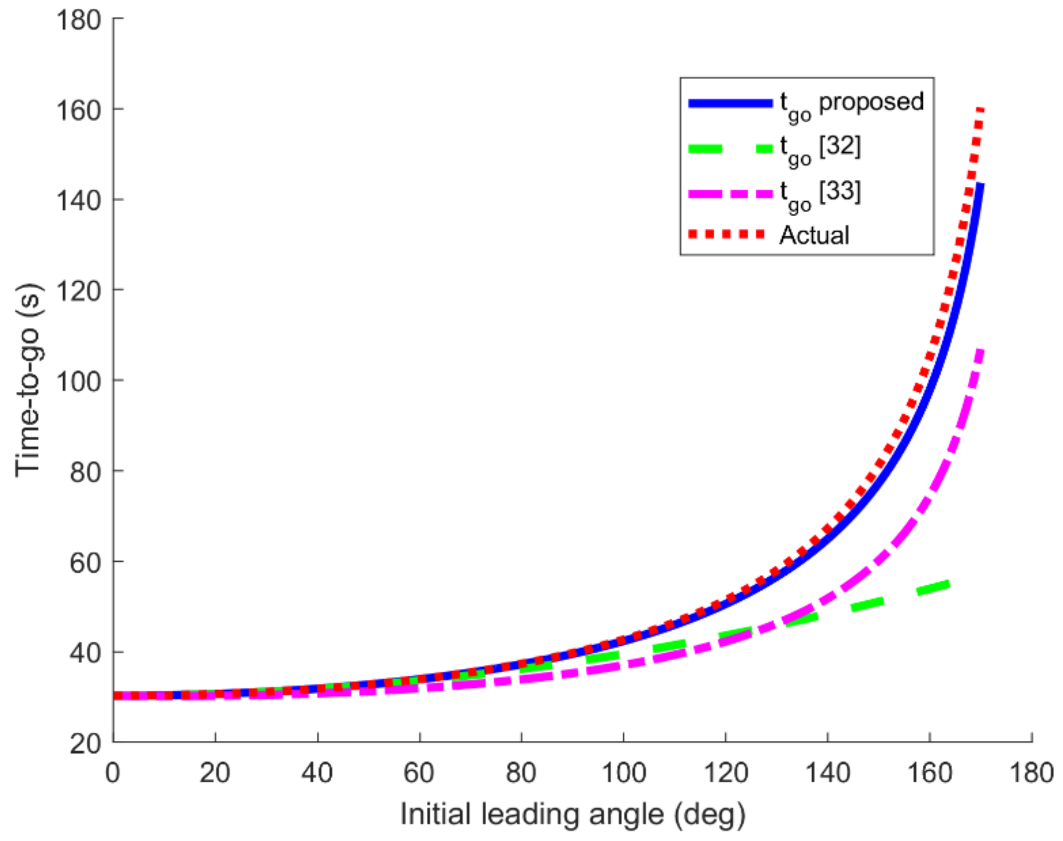
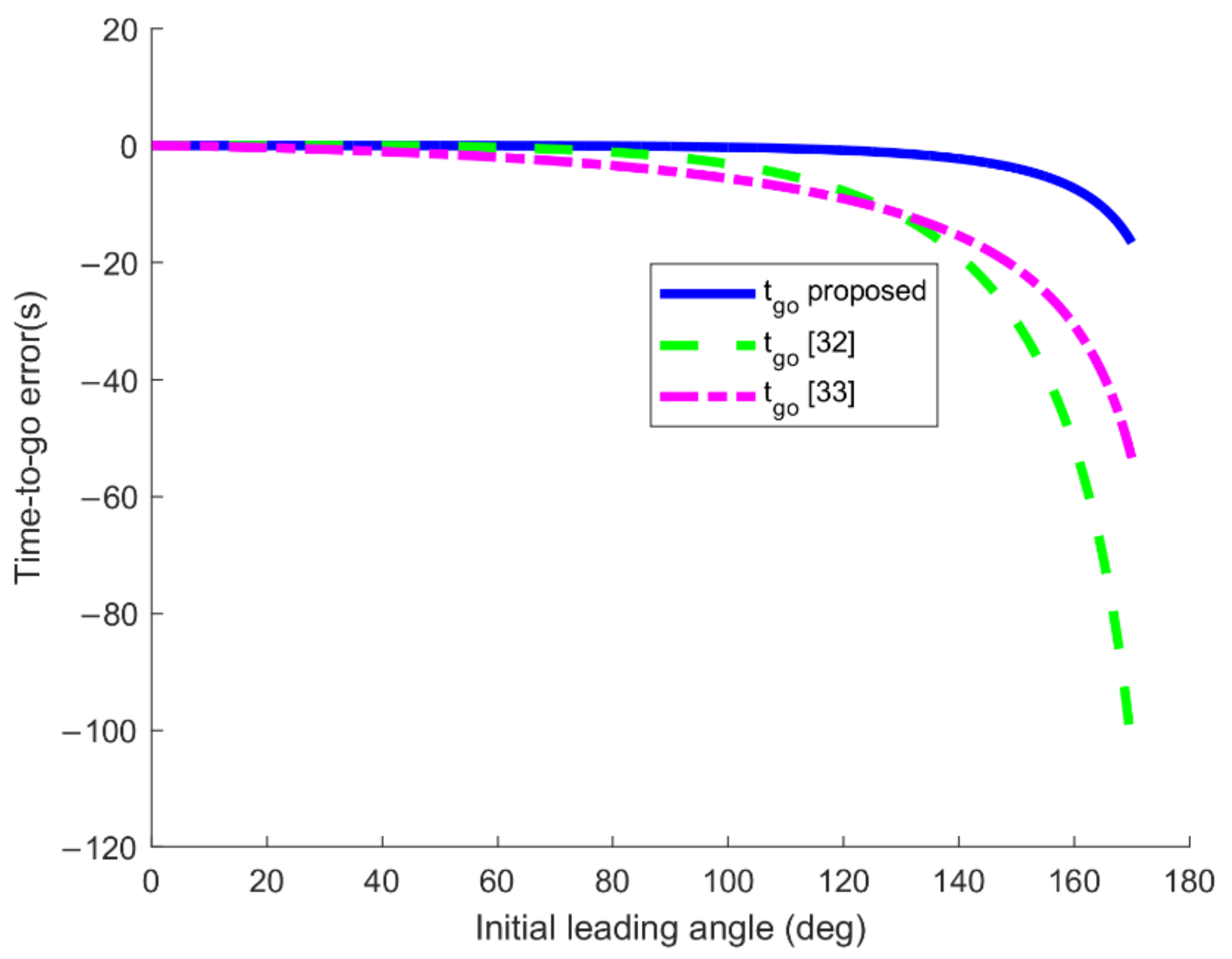
A more accurate time-to-go method compared to the time-to-go estimation methods designed in [32,33] is proposed, and based on which, the MPNG law is designed. The MPNG law is also effective when the initial leading angle is zero, while some existing impact time control guidance laws cannot start in [7,12,13,26].
(2)
The cooperative guidance architecture with centralized coordination is adopted, using the MPNG law as the local guidance, and the desired impact time as the coordination variables, a two-dimensional impact time control cooperative guidance law under constant velocity is designed, numerical simulation results verify the feasibility and applicability of the method.
(3)
The analytic function of velocity with respect to time is derived, and a three-dimensional impact time control cooperative guidance law under time-varying velocity based on desired impact time is designed.
The rest of the paper is organized as follows. In Section 2, the problem statement and motion models are given. The accurate time-to-go estimation method, the MPNG law for impact time control and the two-dimensional impact time control cooperative guidance law under constant velocity are proposed in Section 3. The analytic function of velocity with respect to time, and a multi-missile three-dimensional cooperative guidance law under time-varying velocity based on desired impact time is designed in Section 4. Several numerical simulations are designed in Section 5. The Section 6 gives the conclusion.

2. Problem Statement

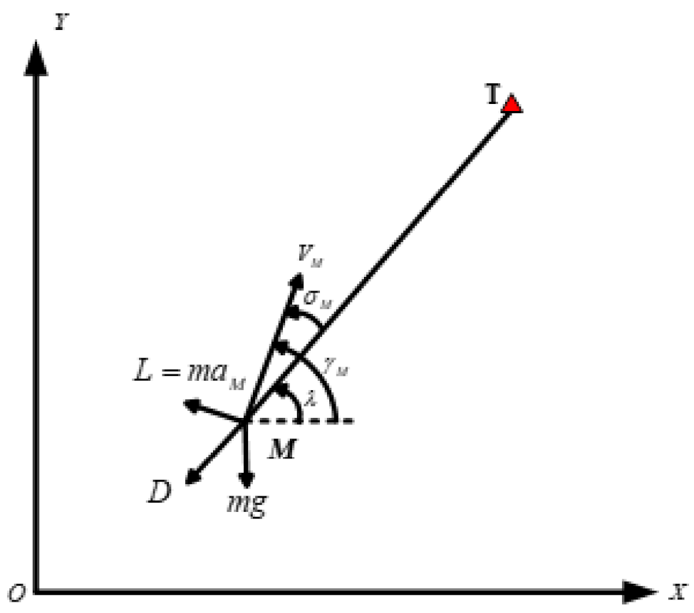
2.1. Mathematical Model of Missile on Two-Dimensional Plan

To facilitate analysis, some assumptions are made in this section:
Assumption 1:
The missile is considered as a mass point, that is, regardless of the effects of the autopilot, which means the acceleration of the missile is the same with the acceleration command.
Assumption 2:
The target is stationary.

2.1.1. The Velocity of Missile Is Constant

Assumption 3:
The missile velocity remains unchanged, because the range is short probably a few kilometers to tens of kilometers.
As shown in Figure 1, the missile and target are denoted as M and T, respectively, and the relative kinematics Equations between them can be expressed as:
r ˙ = V M cos σ M
λ ˙ = V M sin σ M r
r ˙ = V M cos σ M
σ M = γ M λ
In the above Equations, V M is the velocity of missile. The symbol r is the range-to-go. Symbols γ M , λ , σ M and a M represent the flight path angle, the line of sight (LOS) angle, the leading angle and the acceleration command, respectively.

2.1.2. The Velocity of Missile Is Time-Varying

As shown in Figure 1, when the velocity of missile is time-varying, the relative kinematics Equations are as follows:
r ˙ = V M cos σ M
λ ˙ = V M sin σ M r
γ ˙ M = a M / V M
V ˙ M = D + m g sin γ M / m
σ M = γ M λ
In the above Equations, Symbols L and D represent the aerodynamic lift and drag respectively. m is the mass of missile and g is the gravitational acceleration, the meanings of other symbols are the same as Section 2.1.1.
The aerodynamic drag D can be expressed as:
D = C D ρ V M 2 S r e f / 2
where, C D is the drag coefficient, which depend on the angle of attack and Mach number of the missile. ρ is atmospheric density, and exponential atmospheric model is adopted. S r e f is the aerodynamic reference area of the missile.
Substituting Equation (10) into Equation (8), yields:
V ˙ M = C D ρ V M 2 S r e f / 2 + m g sin γ M / m = C D ρ S r e f 2 m + g sin γ M V M 2 V M 2 = C D V M ρ S r e f 2 m + g sin γ M V M V M
Through the analysis of Equation (11), as can be seen, for an unpowered missile, the aerodynamic drag and its own gravity are the main factors affecting the change of velocity. When aerodynamic drag is regarded as the main factor and the effect of gravity can be ignored, assuming that the drag coefficient is constant C D 0 and the atmospheric density is constant, it can be known from [34] that the velocity change rate of the missile can be expressed as:
V ˙ M = K M V M 2
where, K M = C D 0 ρ S r e f / 2 m is the rate coefficient of velocity change, which is constant under the above assumptions.

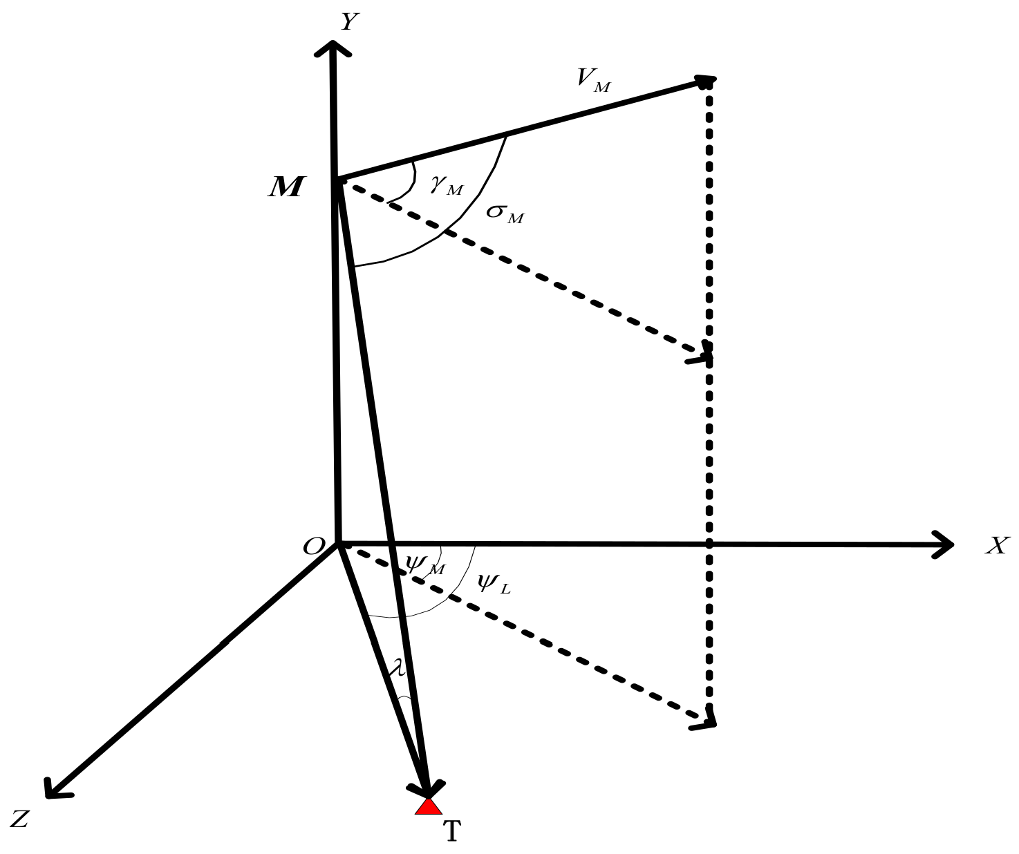
2.2. Mathematical Model of Missile in Three-Dimensional Space

The assumptions are the same as Section 2.1.2. The relationship between missile and target is shown in Figure 2 in three-dimensional space.
Where, O x y z is the ground coordinate system, ψ L , ψ M are the azimuth of the line of sight and the flight path angle, respectively. The meanings of other symbols are the same as Section 2.1.
Then the kinematics Equations of the missile can be expressed as:
x ˙ = V M cos γ M cos ψ M y ˙ = V M sin γ M z ˙ = V M cos γ M sin ψ M
The dynamic Equations of the missile can be expressed as:
V ˙ M = D m g sin γ M γ ˙ M = L cos ν m V M g cos γ M V M ψ ˙ M = L sin ν m V M cos γ M
where, ν is the bank angle, the meanings of other symbols are the same as Section 2.1.2.
The change rate of distance between the missile and target, the azimuth of the line of sight and the line of sight angle can be expressed as:
r ˙ = V M sin γ M sin λ V M cos γ M cos ψ M ψ L cos λ ψ ˙ L = V M cos λ sin ψ M ψ L r cos λ λ ˙ = V M cos γ M sin ψ M ψ L sin λ V M sin γ M cos λ r
where, r represents the distance between missile and target.
The acceleration of the pitch channel is denoted as a z , and the acceleration of the yaw channel is denoted as a y , from Equation (12) we can get that the dynamic Equations of missile can be simplified as:
V ˙ M = K M V M 2 γ ˙ M = a z / V M ψ ˙ M = a y / V M
where, K M = C D 0 ρ S r e f / 2 m is the coefficient of change rate of velocity, which is constant under the above assumptions.

3. Time-to-Go Estimation of PNG Law

3.1. Time-to-Go Estimation When Velocity Is Constant

When the PNG law is adopted, the acceleration is shown as follows:
a M = N V M λ ˙
where, N is the navigation gain and λ ˙ is the rate of the LOS angle.
Substituting Equation (17) into Equation (3), yields:
γ ˙ M = N λ ˙
Differentiating Equation (4) and substituting Equation (18), yields:
σ ˙ M = N 1 λ ˙
Substituting Equation (2) into Equation (19), yields:
σ ˙ M = N 1 V M sin σ M r
It can be obtained from Equations (1) and (20) that:
d σ M d r = σ ˙ M r ˙ = N 1 tan σ M r
Integrating Equation (21) and its solution can be obtained as follows:
r = r 0 sin σ M sin σ M 0 1 N 1
where r 0 is the initial distance and σ M 0 is the initial leading angle. Note that the assumption that σ M 0 , π is used in the derivation. Equations (17)–(22) are first seen in [32].
Substituting Equation (22) into Equation (20), yields:
σ ˙ M = N 1 V M sin σ M r 0 sin σ M sin σ M 0 1 N 1 = K sin σ M N 2 N 1
where, K = N 1 V M r 0 sin σ M 0 1 N 1 . V M is constant, r 0 and σ M 0 are known.
It can be obtained from Equation (23) that:
d t = 1 K sin σ M 2 N N 1 d σ M
Assuming that σ M 0 is small, integrating Equation (24) and using Taylor series expansion, ignoring advanced items, yields:
t t 0 = 1 K σ M 0 σ M sin σ M 2 N N 1 d σ M 1 K σ M 0 σ M σ M σ M 3 6 2 N N 1 d σ M = 1 K σ M 0 σ M σ M 2 N N 1 1 σ M 2 6 2 N N 1 d σ M 1 K σ M 0 σ M σ M 2 N N 1 1 2 N N 1 σ M 2 6 d σ M = 1 K σ M 0 σ M σ M 2 N N 1 + 2 N N 1 σ M N N 1 6 d σ M
Equation (25) can be further simplified as follows:
t = t 0 + r 0 V M 1 + 2 N 6 N 1 2 N 1 σ M 0 2 σ M 0 sin σ M 0 1 N 1 r 0 V M 1 + 2 N 6 N 1 2 N 1 σ M 2 σ M sin σ M 0 1 N 1
When the distance between missile and target is zero, the leading angle σ M is zero. So the t g o at the moment t can be derived as follows:
t g o = r V M 1 + 2 N 6 N 1 2 N 1 σ M 2 σ M sin σ M 1 N 1
Defining
N = 2 N 6 N 1 2 N 1
The method of time-to-go estimation in Equation (27) can be rewritten as follows:
t g o = r V M 1 + N σ M 2 σ M sin σ M 1 N 1
Here, the time-to-go estimations proposed in [32,33] are also given as below:
t g o = r V M 1 + σ M 2 2 2 N 1
t go = K 2 V M 12 ( 1 / 4 ) 1 2 log σ M + 12 ( 1 / 4 ) σ M 12 ( 1 / 4 ) + tan 1 σ M 12 ( 1 / 4 )
where, K = r sin ( σ M )
The precision of Equations (29)–(31) will be compared with the actual time-to-go in Section 5.1. Equation (29) will also be used in the MPNG law.

3.2. Time-to-Go Estimation under Time-Varying Velocity

When the rate of change of velocity is the quadratic function of velocity, integrating Equation (12) can be obtained:
V M t = V M 0 1 + K M V M 0 t
where, V M 0 is the initial velocity of the missile.
When pure proportional guidance law during the flight is adopted, the relative kinematics Equation between the missile and the target can be obtained:
σ ˙ M = N 1 V M t sin σ M r 0 sin σ M sin σ M 0 1 N 1
Substituting Equation (10) into Equation (8), yields:
σ ˙ M = K 1 + K M V M 0 t sin σ M N 2 N 1
where, K = N 1 V M 0 r 0 sin σ M 0 1 N 1 , N is the proportional navigation constant.
From Equation (34), we can get:
1 1 + K M V M 0 t d t = 1 K sin σ M 2 N N 1 d σ M
By integrating Equation (35) and using Taylor expansion series, we can get:
1 K M V M 0 ln 1 + K M V M 0 t 1 + K M V M 0 t 0 = 1 K σ M 0 σ M σ M 2 N N 1 + N 2 N 1 σ M N N 1 6 d σ M
Equation (36) can be further simplified to obtain:
t = 1 + K M V M 0 t 0 e K M V M 0 r 0 V M 0 1 + 2 N 6 N 1 2 N 1 σ M 0 2 σ M 0 sin σ M 0 1 N 1 r 0 V M , 0 1 + 2 N 6 N 1 2 N 1 σ M 2 σ M sin σ M 0 1 N 1 1 K M V M 0
where, t 0 is the initial moment, r 0 is the relative distance between the missile and the target at the initial time, and σ M 0 is the leading angle at the initial time.
When the missile reaches the target, the leading angle is zero, so the time-to-go can be expressed as:
t g o = e K M V M r V M 1 + 2 N 6 N 1 2 N 1 σ M 2 σ M sin σ M 1 N 1 1 K M V M
Defining:
N = N 2 6 N 1 2 N 1
Then the time-to-go expression in Equation (38) can be re-expressed as:
t g o = e K M V M r V M 1 + N σ M 2 σ M sin σ M 1 N 1 1 K M V M

4. The Design of Impact Time Control Cooperative Guidance Law

4.1. Two-Dimensional Impact Time Control Cooperative Guidance Law under Constant Velocity

4.1.1. MPNG Law

The proportional navigation guidance law is a well-known homing guidance method. Based on the conventional proportional navigation law, an impact time control guidance law is proposed as follows:
a M = a P N G + a ε + a s = N V M λ ˙ + K ε N V M 2 sin σ M t ¯ g o t g o + K s N V M 2 sign σ M t ¯ g o t g o
where, a P N G = N V M λ ˙ is the conventional proportional navigation guidance law, a ε = K ε N V M 2 sin σ M t ¯ g o t g o is the time-to-go error feedback term and K ε is a positive constant. a s = K s N V M 2 sign ( σ M ) t ¯ g o t g o is the addition command and the discontinuous function sign σ M is defined as follows:
sign σ M = 1 1 σ M 0 σ M < 0
t ¯ g o is the desired time-to-go, which can also be expressed as follows:
t ¯ g o = t d t
where t d is the desired impact time.
The time derivative of Equation (29) is expressed as follows:
t ˙ g o = r ˙ V M 1 + N σ M 2 σ M sin σ M 1 N 1 + r V M 1 N 1 σ M sin σ M 1 N 1 1 sin σ M σ M cos σ M sin σ M 2 1 + N σ M 2 σ ˙ M + r V M 2 N σ M σ M sin σ M 1 N 1 σ ˙ M
Substituting Equation (1) into Equation (44) yields:
t ˙ g o = K 1 + K 2 σ ˙ M + K 3 σ ˙ M
where
K 1 = cos σ M 1 + N σ M 2 σ M sin σ M 1 N 1
K 2 = r V M 1 N 1 σ M sin σ M 1 N 1 1 sin σ M σ M cos σ M sin σ M 2 1 + N σ M 2
K 3 = r V M 2 N σ M σ M sin σ M 1 N 1
ε T is the impact time error, which can be expressed as follows:
ε T = t ¯ g o t g o
Using Equations (3), (4), (41) and (43), Equation (45) can be rearranged as follows:
t ˙ g o = K 1 + K 2 + K 3 N 1 λ ˙ + K 2 + K 3 K ε sin σ M + K s sign σ M
It can be seen from Equation (41) that if the impact time error equals zero, the law proposed in this paper is equivalent to the PNG law. Equation (50) can be rearranged as follows:
t ˙ g o = 1 + K 2 + K 3 K ε sin σ M + K s sign σ M N V M ε T
Considering the Lyapunov candidate function as follows:
V 1 = 1 2 ε T 2
The time derivative of Lyapunov candidate function can be obtained as follows:
V ˙ 1 = ε T ε ˙ T = K 2 + K 3 K ε sin σ M + K s sign σ M N V M ε T
Using Equations (42), (47) and (48), it can be obtained that K 2 + K 3 K ε sin σ M + K s sign σ M > 0 when σ M π , 0 0 , π and K 2 + K 3 K ε sin σ M + K s sign σ M = 0 when σ M = 0 . Therefore, the Equation (53) is negative-semidefinite when σ M π , π , which means that the MPNG law may also fail when σ M = 0 and ε T 0 . So it necessary to prove that σ M = 0 is not an attractor.
From Equation (2) we can get that λ ˙ = 0 when σ M = 0 and ε T 0 . Equation (41) can be rearranged as follows:
a M = a s = K s N V M 2 sign σ M ε T
Therefore, when σ M = 0 and ε T 0 , the σ ˙ M can be expressed as follows:
σ ˙ M = γ ˙ M λ ˙ = a M V M λ ˙ = K s N V M sign σ M ε T 0
It can also be seen from Equation (55) that σ ˙ M > 0 when ε T > 0 and σ ˙ M < 0 when ε T < 0 , which implies that σ M = 0 is an attractor just for σ M = 0 and ε T = 0 .
Therefore, the MPNG law is effective even if the initial leading angle is zero. In addition, the MPNG law has no singularity.

4.1.2. Impact Time Control Cooperative Guidance Law Based on Coordination Variables

The cooperative guidance architecture with centralized coordination is shown in Figure 3, which consists of the guidance control layer at the bottom and the coordination control layer at the upper level. The guidance control layer is realized by the guidance laws of each formation member, and the coordination control layer is realized by designing coordination variables.
In order to guide multiple missiles to attack the target at the same time, the desired impact time is chosen as the coordination variable and the local guidance adopts MPNG law in this paper. Then the acceleration of the missile can be rewritten by Equation (41) as:
a M = a P N G + a ε + a s = N V M λ ˙ + K ε N V M 2 sin σ M ξ t t g o + K s N V M 2 sign σ M ξ t t g o
In order to minimize the energy consumption of missile formation control, the cost function of the i i = 1 , 2 , , n missile is taken as:
J i ξ = a M , i 2
For a formation containing n members, the upper level selects a centralized coordination strategy. In order to minimize the overall cost of the formation, the centralized coordination function of the formation is chosen as the sum of the cost functions of each member in the formation, that is, the total cost function of the formation is the sum of the control energy of each missile.
J t ξ = i = 1 n a M , i 2
Take the impact time that minimizes the total energy consumption of the entire formation as the desired impact time, namely,
ξ = arg min J t ξ
Defining,
C 1 = N V M λ ˙ C 2 = K ε N V M 2 sin σ M C 3 = K s N V M 2 sign σ M
Equation (56) can be rearranged as follows:
a M = a P N G + a ε + a s = C 1 + C 2 ξ t t g o + C 3 ξ t t g o
The total cost function of formation Equation (58) can be expressed as
J t ξ = i = 1 n C 1 , i + C 2 , i ξ t t g o , i + C 3 , i ξ t t g o , i 2
The ξ partial derivative of Equation (62) is expressed as follows:
J t ξ ξ = 2 i = 1 n a M , i a M , i ξ = 2 i = 1 n C 1 , i C 2 , i + C 3 , i + C 2 , i + C 3 , i 2 ξ t t g o , i
It can be obtained from Equation (58) that:
ξ * = i = 1 n C 2 , i + C 3 , i 2 t + t g o , i C 1 , i C 2 , i + C 3 , i i = 1 n C 2 , i + C 3 , i 2
Defining δ = i = 1 n C 1 , i C 2 , i + C 3 , i / i = 1 n C 2 , i + C 3 , i 2 , Equation (64) can be re-expressed as:
ξ * = i = 1 n C 2 , i + C 3 , i 2 t + t g o , i i = 1 n C 2 , i + C 3 , i 2 + δ
It can be seen from Equation (65) that the desired impact time ξ can be regarded as composed of two parts: the first part is the weighted average of the attack time of each missile, and the second part is an additional item. In the actual process, when the distance between the missile and the target point is relatively short, the additional item δ is very small compared to the first item, usually not in the same order of magnitude. Therefore, the influence of the additional item can be ignored, and the suboptimal solution of the desired impact time can be obtained.
ξ = i = 1 n C 2 , i + C 3 , i 2 t + t g o , i i = 1 n C 2 , i + C 3 , i 2
Let the weight of each missile be w i , and there is w i = C 2 , i + C 3 , i 2 / i = 1 n C 2 , i + C 3 , i 2 , Equation (66) can be re-expressed as:
ξ = i = 1 n w i t + t g o , i
Although the desired impact time obtained is not the optimal solution, one of its advantages is that the physical meaning of the expression is relatively clear, that is, after each member of the formation interacts with information in real time, the attack time determined through mutual negotiation is equivalent to the weighted average of the attack time of each missile.
In summary, when the desired impact time is selected as the coordination variable, the Equation (56) is the cooperative guidance law based on coordination variables designed in this paper.

4.2. Three-Dimensional Impact Time Control Cooperative Guidance Law under Time-Varying Velocity

When the change rate of velocity is a quadratic function of velocity, the expression of time-to-go estimation in two-dimensional plane is given in Section 3.2. On this basis, in order to estimate the time-to-go in three-dimensional space, the guidance laws of pitch channel and yaw channel are designed separately. The pure proportional guidance law is used in the pitch channel, and the guidance law with impact time constraint is used in the yaw channel. The guidance laws of the pitch channel and yaw channel are expressed as follows:
γ ˙ M = N λ ˙ ψ ˙ M = N ψ ˙ L 3 2 1 2 1 + 240 V M x z 5 N V M x z ψ ˙ L 2 r x z 3 e t
where, V M x z is the projection of missile velocity in the XZ plane of yaw channel, V M x z = V M cos γ M . r x z is the projection of the distance between missile and target in the XZ plane, r x z = r cos λ . N is the proportional guidance coefficient. e t is the impact time error, the expression is
e t = t d t t g o
where, t d is the desired impact time, t is the current time, t g o is the estimation of the time-to-go in the yaw channel.
According to the expression of time-to-go estimation in two-dimensional plane in Section 2, the time-to-go estimation in yaw channel can be expressed as:
t g o = e K M x z V M x z r x z V M x z 1 + N η M 2 η M sin η M 1 N 1 1 K M x z V M x z
where, η M is the included angle between the projection of velocity in the XZ plane and the projection of the line of sight in the XZ plane, denoted as the leading angle of yaw channel and meets η M = ψ L ψ M . K M x z is the change rate coefficient of velocity in the XZ plane, and satisfies the following relation:
V ˙ M x z = K M x z V M x z 2
Take the derivative with respect to time of both sides of V M x z = V M cos γ M :
V ˙ M x z = V ˙ M cos γ M V M γ ˙ M sin γ M
From Equations (71) and (72), the coefficient of change rate of V x z with time can be obtained:
K M x z = V ˙ M cos γ M V M γ ˙ M sin γ M / V M x z 2
Equation (68) is denoted as the three-dimensional cooperative guidance law based on the desired impact time.

5. Numerical Simulation

5.1. Comparison of Methods for Time-to-Go Estimation

The time-to-go estimation method proposed in this paper and in [32,33] expressed by Equations (29)–(31) are compared in this Section. The simulation parameters are set to N = 3 , r 0 = 10 , 000 m and V M = 330 m / s , the meanings of which are shown in Section 3.1. The variation curves of the time-to-go and time-to-go error with the initial leading angle under different time-to-go estimation methods are shown in the Figure 4 and Figure 5.
As can be seen from Figure 4 and Figure 5, the estimation errors of the three time-to-go estimation methods increase with the increase of the initial leading angle. When the initial leading angle is less than about 40 deg, the accuracy of the three methods is similar. However, when the initial leading angle is greater than about 40 deg, the estimation accuracy and estimation error convergence speed of the method proposed in this paper are obviously better than the other two estimation methods.

5.2. Performance of MPNG Law

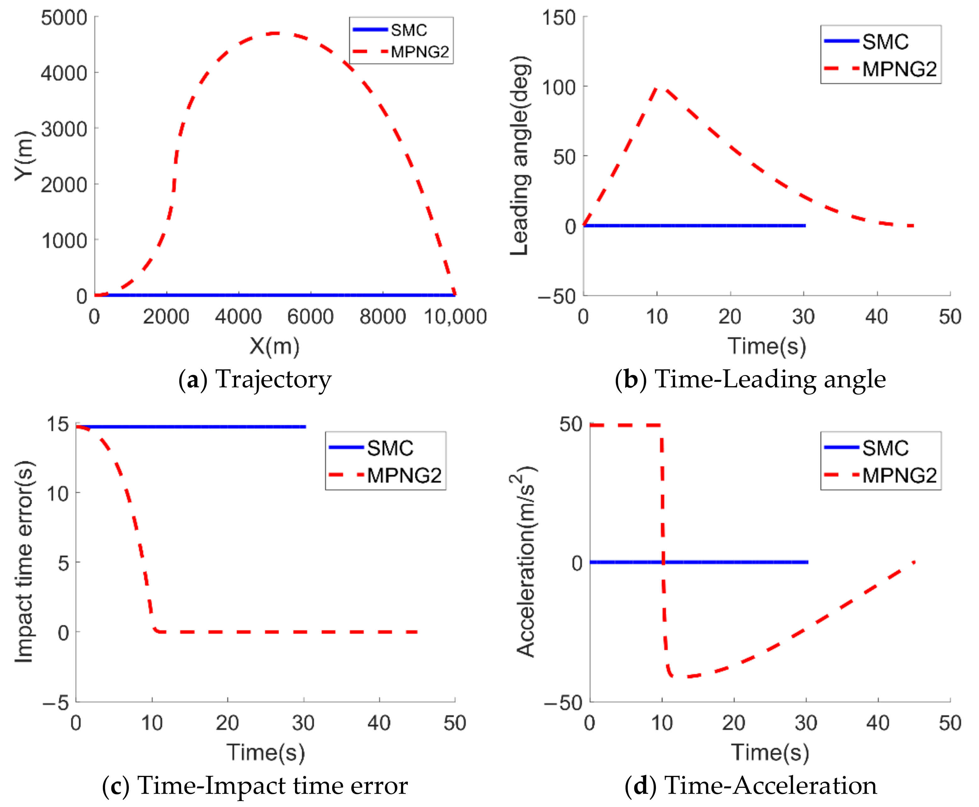
5.2.1. Comparison of the MPNG Law and the SMC Law

The SMC law of [12] can be expressed as follows:
a M = a M e q + a M d i s = 1 + r ˙ V M 1 + σ M 2 2 2 N 1 + r λ ˙ σ M 2 N 1 V M × C s i g n λ ˙ 2 r ˙ λ ˙ r / cos σ M r C r σ M s i g n λ ˙ 2 N 1 V M 2 + K M d i s s i g n S
where
K M d i s = M / s i g n cos σ M r C r σ M s i g n λ ˙ 2 N 1 V M 2
C and M are positive constants.
In this section, the performance of the MPNG law and the SMC law are compared when the initial leading angle is zero. The designated impact time is set to 45 s, the positive constants C ,   M are set to 1 and 200. The other simulation parameters used in this Section are listed in Table 1 and the simulation results are shown in Figure 6.
Figure 6a–d show the missile trajectory, the leading angle, the impact time error and the acceleration command, respectively. It can be seen from Figure 6c that the SMC law cannot drive the missile to attack the target at the designated impact time when the initial leading angle is zero. Therefore, it can also be concluded that the MPNG law is advantageous over the SMC law proposed in [12] when the initial leading angle is zero.

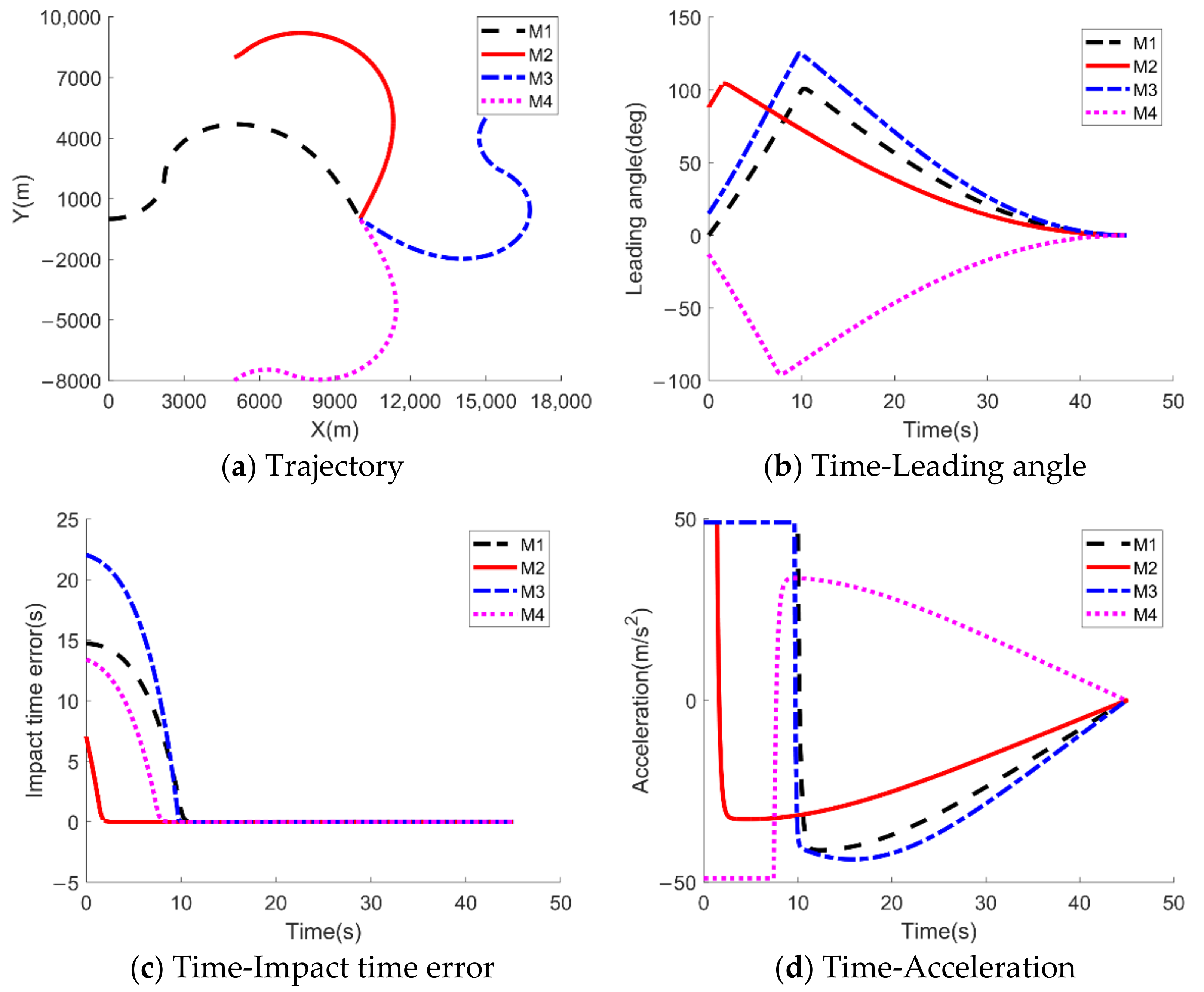
5.2.2. Salvo Attack with the MPNG Law

In Section 5.2.1, the effectiveness of MPNG law is verified when the initial leading angle is 0. This Section verifies the performance of MPNG law in the multi-missile cooperative operation problem. The parameters are set to N = 3 and K ε = K s = 40 / r 0 t g o , 0 . The initial conditions of four missiles are listed in Table 2 and the simulation results are demonstrated in Figure 7.
As can be seen from Figure 7a, four missiles at different positions can reach the designated target at the same time. Figure 7b–d show the variation trend of leading angle, impact time error and acceleration with time, respectively. We can see from Figure 7b that the absolute value of the leading angle increases first, and then decreases gradually with time until it is zero. The impact time error decreases gradually until it converges to zero in Figure 7c and the acceleration also converges to zero at terminal time, as shown in Figure 7d. Figure 7a–d show that MPNG law is effective and applicable in cooperative operation.

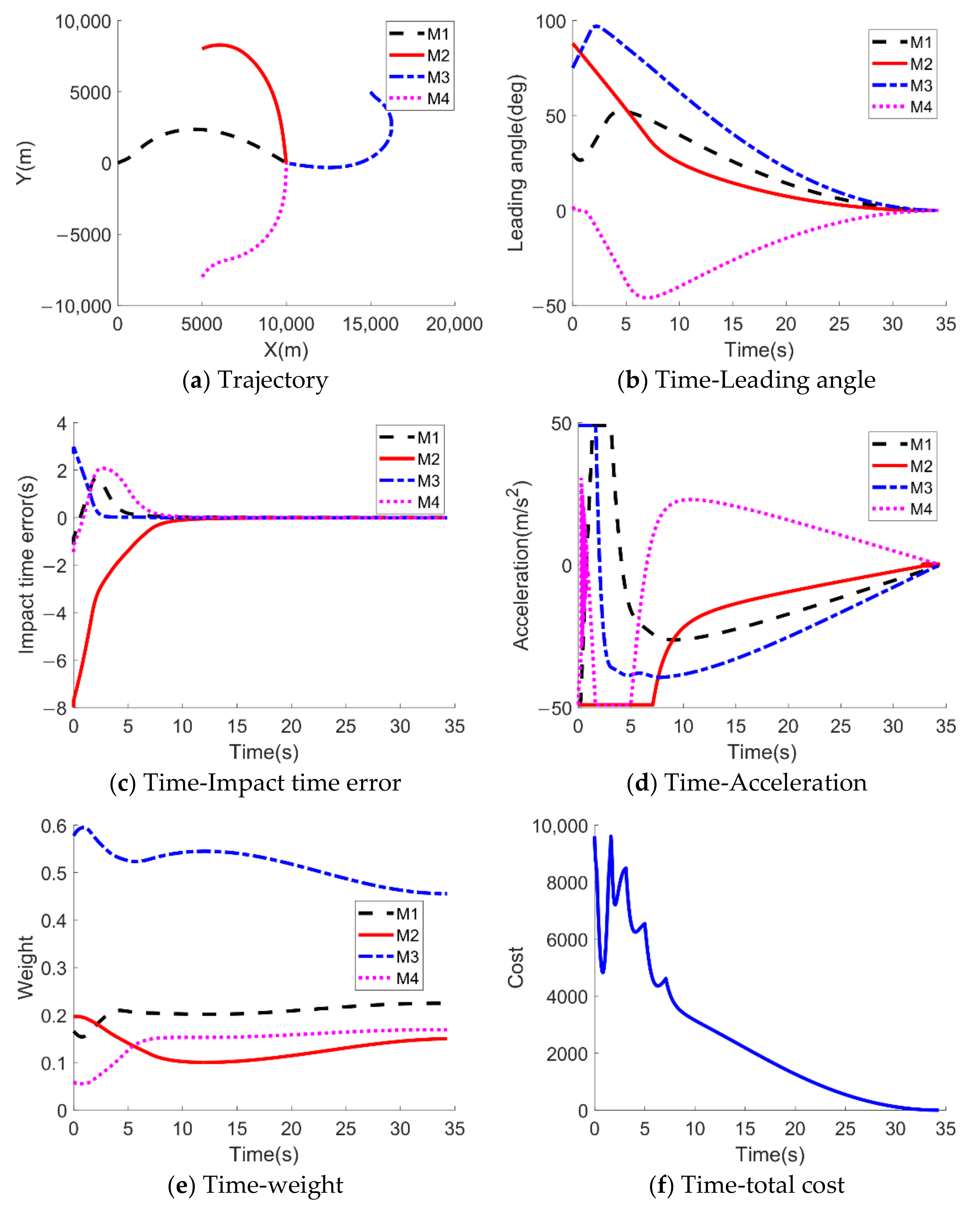
5.3. Performance of Two-Dimensional Impact Time Control Cooperative Guidance Law under Constant Velocity

In order to verify the impact time cooperative guidance law based on coordination variables designed in this paper, the following simulations are carried out. Suppose that at the initial moment, four missiles take off from different positions and need to reach the designated target point at the same time. The initial flight path angles of four missiles are 30, 30, −60, 60 deg respectively. Other parameters are same as Section 5.2.2 and the simulation results are demonstrated in Figure 8.
Figure 8a–f show the missile trajectory, the leading angle, the impact time error, the acceleration command, the weight coefficient of each missile and the change curve of the total cost of formation calculated according to Equation (58) over time. It can be seen from the Figures that during the flight of the four missiles, the desired impact time obtained through mutual information exchange is 34.29 s, and all four missiles can reach the designated target point within the calculated coordinated impact time. It can be seen from Figure 8c that the coordination variable converges faster, and the impact time error of each missile gradually converges to zero. It can be seen from Figure 8e that the weight coefficient of missile 3 is relatively large, so it has the greatest impact on the result of the negotiation. Therefore, the impact time of missile 3 is the first to converge to 0, this is verified in Figure 8c. It can be seen from Figure 8f that, in order to achieve the cooperative attack of multiple missiles, the total cost of formation members is relatively large in the initial stage. As the subsequent acceleration command amplitude of each missile decreases, the total cost of formation gradually decreases until it converges to 0.
In order to illustrate the optimality of the desired impact time obtained through negotiation, Figure 9 shows the curve of the total cost in formation flying with the impact time of 40 s and 45 s, which are compared to the total cost of formation varies with time under the cooperative condition.
It can be seen from Figure 9 that when the guidance law based on coordination variables is adopted, the total formation cost spent during the flight of the missile formation is less than the total formation cost under the desired impact time, which illustrates the optimality of the designated impact time obtained through negotiation.

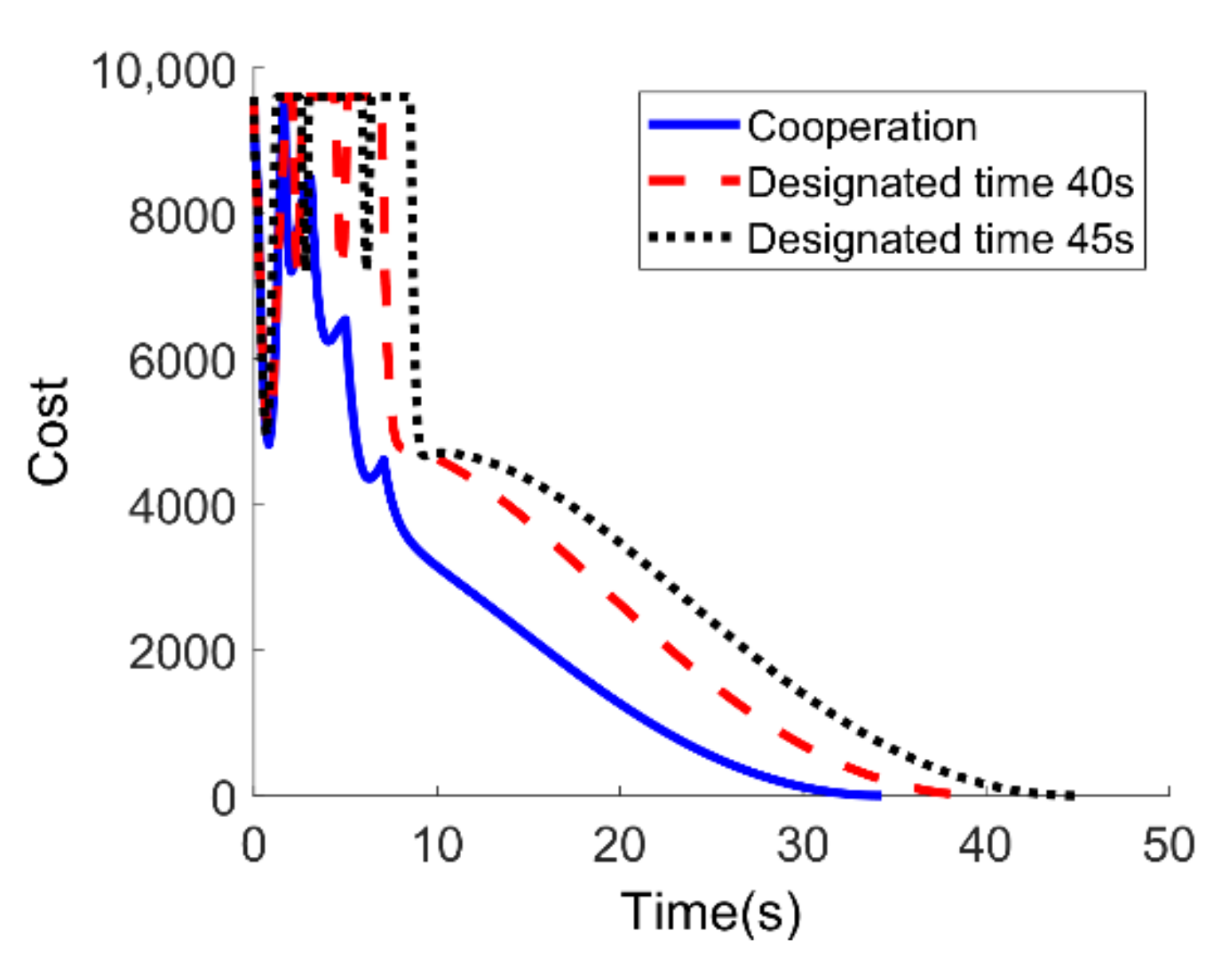
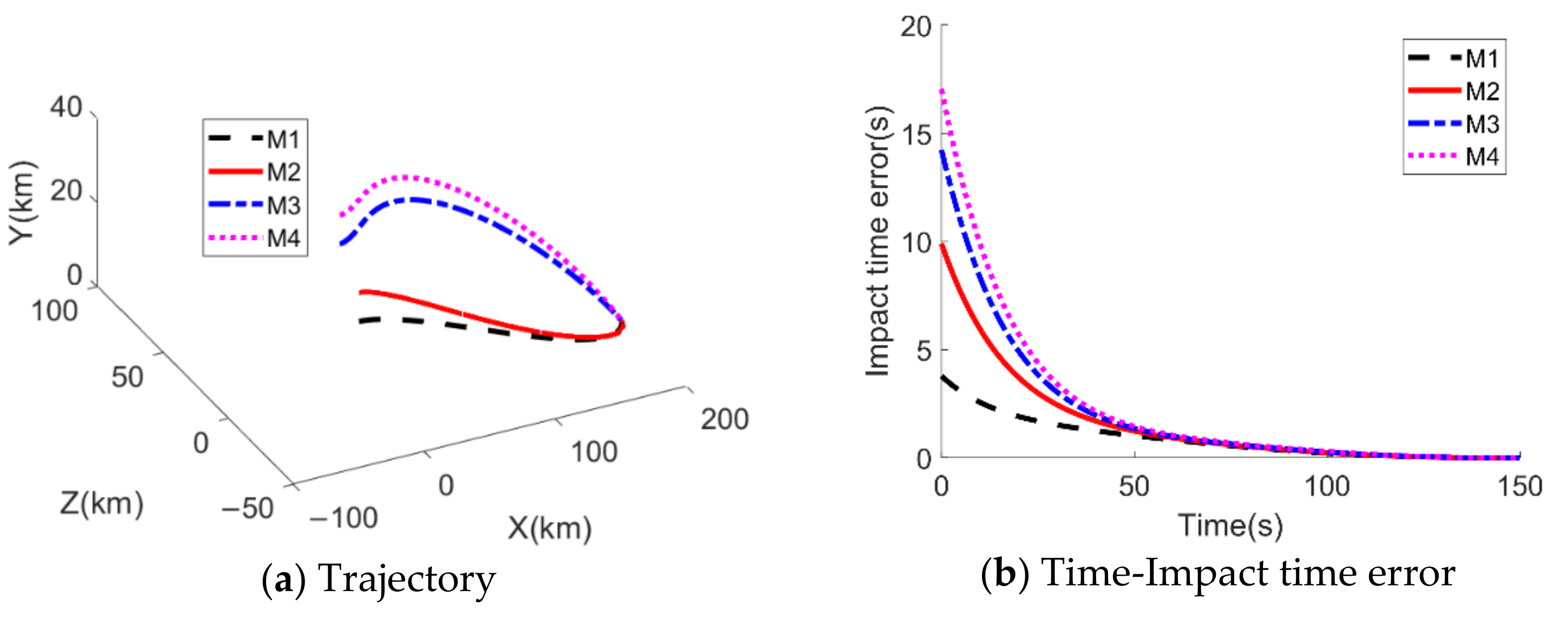
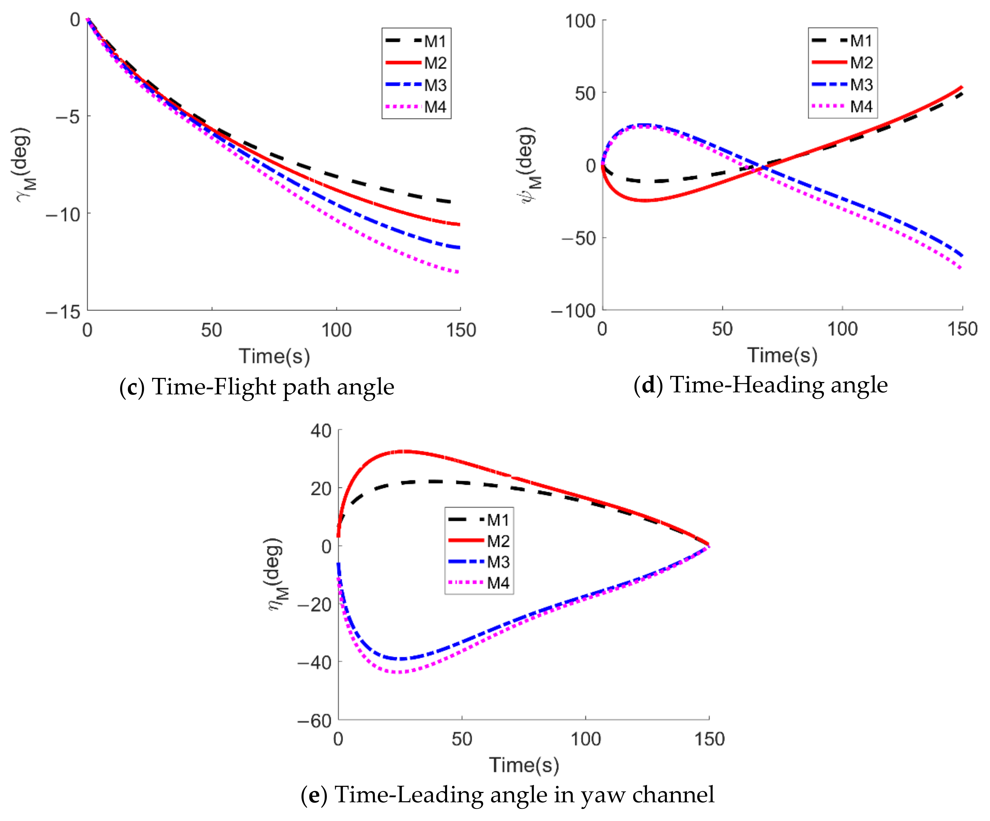
5.4. Performance of Three-Dimensional Impact Time Control Cooperative Guidance Law under Time-Varying Velocity

Considering the impact time constraint, the designated impact time is 150 s, and the other simulation parameters remain unchanged. The simulation results of the three-dimensional cooperative guidance law based on the desired impact time are shown in Figure 10.
Figure 10a–e show the variation curves of the three-dimensional flight trajectory, impact time error, flight path angle, heading angle and the leading angle of velocity in yaw channel with time. It can be seen from Figure 10a that all four missiles can reach the specified target point. As can be seen from Figure 10b, the impact time errors of the four missiles converge to 0 at the terminal moment, which satisfies the requirement of attacking the target at the same time within the specified time. As can be seen from Figure 10e, the amplitude of the leading angle of velocity in the yaw channel increases at the initial stage, and then gradually converges to 0. This is because, in order to meet the impact time constraint, the leading angle of the missile in the initial stage increases and maneuvers laterally to extend the flight time. At the same time, the lateral maneuver increases the amplitude of heading angle in Figure 10d in the initial stage.
It can be seen from Figure 10c that the trend of flight path angle has almost no change. As can be seen from Figure 10e, the leading angle of yaw channel converges to 0 at the terminal time.

6. Conclusions

This paper aims to avoid problem of multi-missile cooperative attack on stationary target, a two-dimensional impact time control cooperative guidance law under constant velocity and a three-dimensional impact time control cooperative guidance law under time-varying velocity are proposed. First, a more accurate time-to-go estimation method is derived, which is more accurate than the existing methods in [32,33]. Based on the time-to-go estimation method, the MPNG law is designed, which is also effective when the initial leading angle is zero. Second, a two-dimensional impact time control cooperative guidance law under constant velocity is designed under cooperative guidance architecture with centralized coordination, which is using the MPNG law as the local guidance, and the desired impact time as the coordination variables. Finally, a method of solving the expression of velocity is derived, and the analytic function of velocity with respect to time is given, a three-dimensional impact time control cooperative guidance law under time-varying velocity based on desired impact time is designed. Simulation results verify the effectiveness of the method proposed in this paper.

Author Contributions

Conceptualization, Z.J. and J.G.; formal analysis, Q.X. and Z.J.; methodology, Z.J., T.Y. and J.G.; software, Z.J.; validation, Z.J. and J.G.; writing—original draft, Z.J.; writing-review and editing, T.Y. and Q.X. All authors have read and agreed to the published version of the manuscript.

Funding

This research received no external funding.

Institutional Review Board Statement

Not applicable.

Informed Consent Statement

Not applicable.

Data Availability Statement

Not applicable.

Conflicts of Interest

The authors declare no conflict of interest.

References

  1. Lyu, T.; Guo, Y.; Li, C.; Ma, G.; Zhang, H. Multiple missiles cooperative guidance with simultaneous attack requirement under directed topologies. Aerosp. Sci. Technol. 2019, 89, 100–110. [Google Scholar] [CrossRef]
  2. Jiang, H.; An, Z.; Chen, S.; Xiong, F. Cooperative guidance with multiple constraints using convex optimization. Aerosp. Sci. Technol. 2018, 79, 426–440. [Google Scholar] [CrossRef]
  3. Jeon, I.S.; Lee, J.I.; Tahk, M.J. Impact-time-control guidance law for anti-ship missiles. IEEE Trans. Control Syst. Technol. 2006, 14, 260–266. [Google Scholar] [CrossRef]
  4. Jeon, I.S.; Lee, J.I.; Tahk, M.J. Impact-Time-Control Guidance with Generalized Proportional Navigation Based on Nonlinear Formulation. J. Guid. Control Dyn. 2016, 39, 1887–1892. [Google Scholar] [CrossRef]
  5. Tahk, M.J.; Sang, D.K. Guidance Law Switching Logic Considering the Seeker’s Field-of-view Limits. Proc. Inst. Mech. Eng. Part G J. Aerosp. Eng. 2009, 223, 1049–1058. [Google Scholar]
  6. Zhang, Y.; Wang, X.; Ma, G. Impact time control guidance law with large impact angle constraint. Proc. Inst. Mech. Eng. Part G J. Aerosp. Eng. 2015, 229, 2119–2131. [Google Scholar] [CrossRef]
  7. Zhang, Y.; Wang, X.; Wu, H. Impact time control guidance law with field of view constraint. Aerosp. Sci. Technol. 2014, 39, 361–369. [Google Scholar] [CrossRef]
  8. Ma, G.; Zhang, Y. Impact time control guidance law with seeker field of view limitation. J. Ballist. 2013, 25, 6–11. [Google Scholar]
  9. Cho, N.; Kim, Y. Modified Pure Proportional Navigation Guidance Law for Impact Time Control. J. Guid. Control Dyn. 2016, 39, 1–21. [Google Scholar] [CrossRef]
  10. He, S.; Lin, D. Three-Dimensional Optimal Impact Time Guidance for Antiship Missiles. J. Guid. Control Dyn. 2019, 42, 941–948. [Google Scholar] [CrossRef] [Green Version]
  11. Ghosh, S.; Ghose, D.; Raha, S. Three dimensional PN based impact angle control for higher speed nonmaneuvering targets. In Proceedings of the 2013 American Control Conference, Washington, DC, USA, 17–19 June 2013. [Google Scholar]
  12. Kumar, S.R.; Ghose, D. Sliding mode control based guidance law with impact time constraints. In Proceedings of the 2013 American Control Conference, Washington, DC, USA, 17–19 June 2013. [Google Scholar]
  13. Kumar, S.R.; Ghose, D. Impact time guidance for large heading errors using sliding mode control. IEEE Trans. Aerosp. Electron. Syst. 2015, 51, 3123–3138. [Google Scholar] [CrossRef]
  14. Cho, D.; Kim, H.J.; Tahk, M.J. Nonsingular Sliding Mode Guidance for Impact Time Control. J. Guid. Control Dyn. 2016, 39, 61–68. [Google Scholar] [CrossRef]
  15. Harl, N.; Balakrishnan, S.N. Impact Time and Angle Guidance With Sliding Mode Control. IEEE Trans. Control Syst. Technol. 2012, 20, 1436–1449. [Google Scholar] [CrossRef]
  16. Talole, S.E.; Phadke, S.B. Robust Input-Ouput Linearisation Using Uncertainly and Disturbance Estimation. Int. J. Control 2009, 82, 1794–1803. [Google Scholar] [CrossRef]
  17. Saleem, A.; Ratnoo, A. Lyapunov-Based Guidance Law for Impact Time Control and Simultaneous Arrival. J. Guid. Control Dyn. 2016, 39, 164–173. [Google Scholar] [CrossRef]
  18. Liu, X.; Han, Y.; Li, P.; Guo, H.; Wu, W. Target Tracking Enhancement by Three-Dimensional Cooperative Guidance Law Imposing Relative Interception Geometry. Aerospace 2020, 8, 6. [Google Scholar] [CrossRef]
  19. Cheng, Z.; Wang, B.; Liu, L.; Wang, Y. A composite impact-time-control guidance law and simultaneous arrival. Aerosp. Sci. Technol. 2018, 80, 403–412. [Google Scholar] [CrossRef]
  20. Wang, P.; Guo, Y.; Ma, G.; Wie, B. New Differential Geometric Guidance Strategies for Impact-Time Control Problem. J. Guid. Control Dyn. 2019, 42, 1982–1992. [Google Scholar] [CrossRef]
  21. Hu, Q.; Han, T.; Xin, M. Sliding-Mode Impact Time Guidance Law Design for Various Target Motions. J. Guid. Control Dyn. 2019, 42, 136–148. [Google Scholar] [CrossRef]
  22. Kumar, S.R.; Ghose, D. Impact time and angle control guidance. In Proceedings of the AIAA Guidance, Navigation, and Control Conference, Kissimmee, FL, USA, 5–9 January 2015. [Google Scholar]
  23. Kumar, S.R.; Ghose, D. Sliding mode guidance for impact time and angle constraints. Proc. Inst. Mech. Eng. Part G J. Aerosp. Eng. 2017, 232, 2961–2977. [Google Scholar] [CrossRef]
  24. Ryoo, C.K.; Cho, H.; Tahk, M.J. Optimal guidance laws with terminal impact angle constrain. J. Guid. Control Dyn. 2005, 28, 724–732. [Google Scholar] [CrossRef]
  25. Hou, Z.; Yang, Y.; Liu, L.; Wang, Y. Terminal sliding mode control based impact time and angle constrained guidance. Aerosp. Sci. Technol. 2019, 93, 105142. [Google Scholar] [CrossRef]
  26. Zhang, Y.; Ma, G.; Liu, A. Guidance law with impact time and impact angle constraints. Chin. J. Aeronaut. 2013, 26, 960–966. [Google Scholar] [CrossRef] [Green Version]
  27. Chen, X.; Wang, J. Optimal control based guidance law to control both impact time and impact angle. Aerosp. Sci. Technol. 2019, 84, 454–463. [Google Scholar] [CrossRef]
  28. Zhao, S.; Rui, Z. Multi-missile Cooperative Guidance Using Coordination Variables. Acta Aeronaut. Astronaut. Sin. 2008, 29, 1605–1611. [Google Scholar]
  29. Kumar, S.R.; Ghose, D. Cooperative Rendezvous Guidance using Sliding Mode Control for Interception of Stationary Targets. IFAC Proc. Vol. 2014, 47, 477–483. [Google Scholar] [CrossRef]
  30. Zhang, B.; Song, J.; Song, S. Research on multi-missile coordinated guidance with angle constraints. J. Proj. Rocket. Missiles Guid. 2014, 34, 13–15. [Google Scholar]
  31. Zhao, E.; Wang, S.; Chao, T.; Yang, M. Multiple missiles cooperative guidance based on leader-follower strategy. In Proceedings of the 2014 IEEE Chinese Guidance, Navigation and Control Conference, Yantai, China, 8–10 August 2014. [Google Scholar]
  32. Jeon, I.S.; Lee, J.I.; Tahk, M.J. Homing guidance law for cooperative attack of multiple missiles. J. Guid. Control Dyn. 2010, 33, 275–280. [Google Scholar] [CrossRef]
  33. Dhananjay, N.; Ghose, D. Accurate Time-to-Go Estimation for Proportional Navigation Guidance. J. Guid. Control Dyn. 2014, 37, 1378–1383. [Google Scholar] [CrossRef]
  34. Zhu, C.; Xu, G.; Wei, C.; Cai, D.; Yu, Y. Impact-Time-Control Guidance Law for Hypersonic Missiles in Terminal Phase. IEEE Access 2020, 8, 44611–44621. [Google Scholar] [CrossRef]
Figure 1. Motion model of missile on two-dimensional plan.
Aerospace 08 00231 g001
Figure 2. Motion model of missile in three-dimensional space.
Aerospace 08 00231 g002
Figure 3. Cooperative guidance architecture with centralized coordination.
Aerospace 08 00231 g003
Figure 4. Time-to-go with different initial leading angles.
Aerospace 08 00231 g004
Figure 5. Time-to-go error with different initial leading angles.
Aerospace 08 00231 g005
Figure 6. Simulation 4.2.1.
Aerospace 08 00231 g006
Figure 7. Salvo attack against a stationary target.
Aerospace 08 00231 g007
Figure 8. Simulation 5.3.
Aerospace 08 00231 g008
Figure 9. The designated impact time and the total cost of the formation under coordination condition.
Aerospace 08 00231 g009
Figure 10. Simulation results of three-dimensional cooperative guidance law based on desired impact time.
Aerospace 08 00231 g010aAerospace 08 00231 g010b
Table 1. Simulation parameters for Section 5.2.
Initial   Position   of   the   Missile   X 0 , Y 0 (0,0) km
Target position X T , Y T (10,0) km
Velocity of the missile V M 330 m/s
Initial flight path angle γ M , 0 0 deg
Table 2. Simulation parameters for salvo attack.
MissilesInitial Position (km)Target Position (km)Velocity (m/s)Initial Flight Path Angle (Deg)Designated Impact Time (s)
M1(0,0)(10,0)330045
M2(5,8)32030
M3(15,5)310−120
M4(5,−8)30045
Publisher’s Note: MDPI stays neutral with regard to jurisdictional claims in published maps and institutional affiliations.

