1. Introduction
In this paper, we present in detail for the first time one of the challenges that practitioners face in the application of MDO to airframe structural design: the need to consider in detail the influence on the sizing of primary structures of some components, such as manholes, cut-outs, bulkheads, and stringer run-outs. After reviewing the available methodologies for MDO, the current practice in the industry and its limitations, we conclude by summarising the problem characteristics, which might allow this challenge to be overcome.
1.1. The Design Process Paradox
The design of any complex product, not only in the aircraft industry, starts with a list of requirements or desired characteristics. At the beginning, the designers are free to make any design decision, but as soon as the process starts, each new decision is influenced by the previous ones. An example from our experience in aircraft design is that one must first define the wing position and then design its profile and aspect ratio.
Although similar products developed in the past may serve as a reference, at the beginning, the designers have a limited knowledge of how the new concept will match the target requirements, simply because a design, which has not yet been defined in detail, cannot be fully evaluated.
If during the design process the solution fails to satisfy the design requirements due to constraints imposed in previous steps, the designers must seek alternative solutions. This means retracing their steps and remodelling part of the work, as represented in
Figure 1a. In the earlier mentioned example, the designers would fail to find a satisfactory wing profile and aspect ratio and be forced to change its position.
Since looking for alternative solutions requires going back to a previous state and advancing once again from there, setbacks result in additional work and time delays and consequently an increased design cost. While some degree of iteration is inevitable, major setbacks discovered in the late development stages must be avoided at all costs [
1].
As design advances, the increasing cost of going back progressively limits the design freedom. If problems are discovered late, it may be preferable to stick with a sub-optimal solution, because of the committed money cost.
This leads to a problem known as the
design process paradox [
2]: at the beginning, when the design freedom is maximal, little information is available to guide the decision-making, while instead towards the end, as more information is acquired, the design is set and the initial freedom is lost. The paradox is depicted in
Figure 1b.
1.2. Aircraft Industry Strategies to Address the Paradox
The aircraft industry addresses this problem in two ways:
Working in parallel on multiple models during early design,
Using a multidisciplinary approach to design.
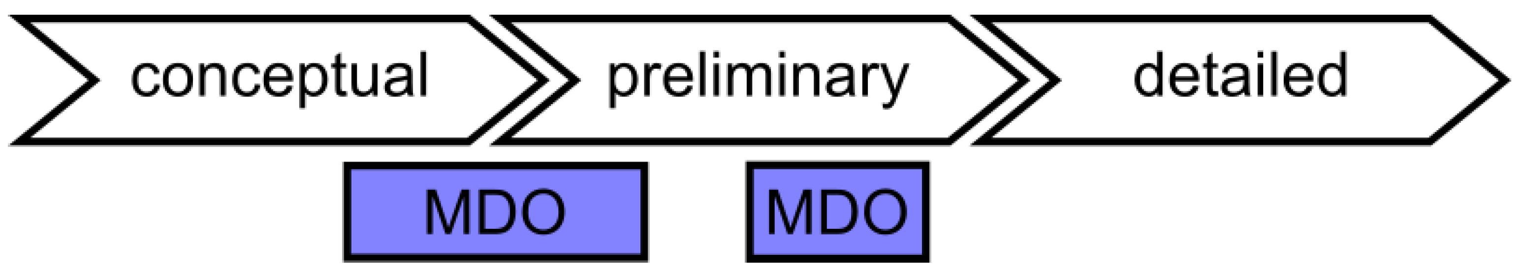
The process of aircraft design is divided in three stages [
3]: conceptual, preliminary and detailed. During conceptual design, when the committed costs are small, multiple models are studied in parallel. This leads to an increased knowledge, which is vital to avoid major setbacks. Multiple possibilities are explored, and the least promising designs are quickly discarded without an impact on cost. This is the first strategy commonly adopted by the industry.
As each decision influences all decisions downstream, the first design choices are critical. Multidisciplinary Design Optimisation (MDO) is a powerful and well-established approach for designing an aircraft while concurrently considering several requirements. Bringing forward the use of MDO to the transition from conceptual to preliminary design and advancing the design of each concept in parallel is the second strategy adopted to prevent major setbacks.
1.3. Ignoring Local Non-Regular Areas Potentially Thwarts MDO Benefits
Despite these efforts, setbacks are still possible. For example, when MDO is applied to airframe sizing, which is the focus of this paper, a known problem is related to the presence of
non-regular areas inside the structure. These comprise all those parts whose complex mechanical behaviour is not captured by the coarse models used for MDO. Common examples are: stringer run-outs, large cut-outs and bulkheads. The interaction of these local models with the global model may have an influence on the behaviour of the entire structure. For example, if a sequence of skin panels presents with a series of manholes and inspection holes, each hole creates an opportunity for the load paths to split. This leads to non-linear changes in the structural behaviour, which cannot be captured, if non-regular areas are ignored during the global optimisation. The influence of these local details on the overall structure is discussed in detail in
Section 4; here, it suffices to say that neglecting the study of them may lead to major setbacks only discovered during detailed design.
1.4. The Case for Global–Local MDO
In this paper, we delineate the problem of the global influence of local details and discuss the characteristics of the approach needed to extend an existing MDO architecture [
3]. In short, this combines the efficient solution of the global problem with the ability to capture the mechanical behaviour of local parts for the purpose of evaluating strength and buckling constraints.
Ultimately this is the strategy of bringing knowledge of non-regular areas to the early phases, where changes are cheap and design decisions are crucial.
1.5. Structure of the Article
This paper is structured in the following way.
Section 2 presents a literature review on MDO and its application to aircraft design.
Section 3 and
Section 4 describe, respectively, the current approach and its limitations. Lastly,
Section 5 contains the conclusion.
2. Current State-of-the-Art for MDO and Its Application to Airframe Sizing
An early mention of the paradox in sequential design, with specific reference to the aircraft industry, is found in [
4] by Sobieszczanski-Sobieski et al. Since the design of an aircraft requires taking into account several disciplines and the interaction of several subsystems, the authors suggest the use of Multidisciplinary Design Optimisation (MDO), to overcome the paradox and reach an optimal design.
2.1. General Aspects of Multidisciplinary Design Optimisation
2.1.1. MDO Optimisation Problem
A Multidisciplinary Design Optimisation (MDO) problem is a classical optimisation problem of the form:
where
f is the objective function,
g and
h are the inequality and equality constraints, respectively,
x are the design variables and
y is the solution of the Multidisciplinary Analysis (MDA):
The solution of the optimisation problem is bound to the solution of the MDA, since
f,
g,
h and their derivatives depend on
y, as represented in
Figure 2.
2.1.2. Internal Structure of the Multidisciplinary Analysis
The MDA naturally breaks down in multiple Contributing Analyses (CAs), each providing part of the solution .
Let the solution variables of the
ith contributing analysis,
, be called
state variables. These depend on the solution variables of other CAs,
, as well as on the design variables
. The
ith contributing analysis can be formulated as:
where
indicates the set of CAs coupled with the
ith CA, thus
.
The
ith CA can therefore be modelled as a system, as in
Figure 3, receiving
,
as an input and generating
as an output.
The MDA is a complex but structured problem, which can be seen as the combination of smaller sub-problems, coupled as in
Figure 4.
2.1.3. Difference between State and Coupling Variables
As a matter of fact, each CA does not depend on the
state variables of other CAs directly. It depends on them through a smaller subset of variables, called
coupling variables and denoted with
. The
ith CA can be modelled more precisely as in
Figure 5, and its formulation can be written as:
2.1.4. Contributing Analyses Result from Disciplines or Substructures
Since the coupling variables are fewer than the state variables, the CAs are coupled together but also partially independent. It is because of this that representing the MDA as a structured problem makes sense. In other words, the decomposition of the MDA in multiple CAs is not arbitrary but such that, for each CA, the number of coupling variables is much smaller than the number of state variables.
This often happens along interdisciplinary lines and physical boundaries, so it is common to consider different disciplines and substructures as part of separate contributing analyses.
2.1.5. MDO Architecture
The key to efficiently solve an MDO problem is to exploit the internal structure problem and decompose it appropriately. Depending on the internal couplings and their strength, different ways of nesting optimisation and analysis solutions might prove more effective in reducing computational cost. In this paper, the structure of the algorithm applied to solve the MDO problem is called MDO architecture, as in [
5].
2.2. Classification of MDO Architectures
Following the example of Cramer et al. in [
6,
7], MDO architectures can be classified as Multidisciplinary Feasible (MDF), Individual Discipline Feasible (IDF) and All-At-Once (AAO). All of these are based on the same optimisation procedure, depicted in
Figure 6, but the difference lies in a different treatment of the analysis block, stemming from radically different definitions of the underlying optimisation problems.
Another aspect in the classification of MDO architectures is the distinction between monolithic and distributed, which is introduced at the end of this subsection and further described in
Section 2.3.
2.2.1. Multidisciplinary Feasible
MDF architectures represent the traditional approach and are the most intuitive to understand. As represented in
Figure 7, an MDF architecture is essentially an optimisation procedure, which solves an MDA at each iteration.
It solves the following problem:
where
is the solution of the MDA:
.
2.2.2. Individual Discipline Feasible
Another possibility is to break the coupling between disciplines, as represented in
Figure 8. Instead of directly providing each analysis
i with the required coupling variable
, computed as the response of the analysis
j, a value
is provided by the optimiser instead. In this way, each analysis can be solved independently, and the optimiser becomes responsible for enforcing the feasibility among disciplines through the consistency constraint
.
This strategy is known as Individual Discipline Feasible (IDF). As in MDF, each CA satisfies the condition for individual discipline feasibility:
but, in contrast to MDF, it does not satisfy the condition for interdisciplinary feasibility:
In other words, in each optimisation iteration, each discipline is solved with the given input, but it is not guaranteed that the input of each discipline matches the output of the coupled CAs, as represented in
Figure 9. The optimisation problem can be written as:
2.2.3. All-at-Once
The third option is All-At-Once (AAO). In this case, the optimiser directly operates on the state variables
and the coupling variables copies
. It is not only responsible for coupling the CAs but also for satisfying each residual equation, as represented in
Figure 10. Therefore, during the optimisation, the design may be infeasible with respect to the single discipline, as well as with respect to the interdisciplinary coupling. Only at convergence, the design is guaranteed to respect both: individual and interdisciplinary feasibility.
The first example of AAO was Simultaneous Analysis and Design (SAND), proposed by Haftka in [
8]. Instead of iteratively solving the analysis within each optimisation iteration, SAND treats the response variables as design variables and adds an equality constraint to ensure individual discipline feasibility.
In the case of a linear static analysis, SAND would transform the problem:
solved by repeatedly solving
for each
in the following optimisation problem:
The same idea can be applied if the underlying analysis is an MDA.
2.2.4. Monolithic and Distributed Architectures
Thus far, we assumed the entire procedure to be based on one unique optimisation loop. When this is the case, the architecture is called monolithic. The alternative is a procedure that includes multiple optimisation procedures. When this is the case, the architecture is called distributed.
Figure 11 illustrates the difference between the two.
In order to use a distributed architecture, the MDO problem must be decomposed in multiple optimisation problems. Since there are several ways of decomposing the problem, the topic of distributed architectures is rather complex. The next subsection is therefore entirely dedicated to distributed architectures.
2.3. Distributed Architectures
When the optimisation problem is decomposed into multiple sub-problems, a new challenge emerges: the coordination of the sub-problems. Many architectures are based on a two-level decomposition of the MDO problem: an upper system-level and a lower one with multiple subsystems. The coordination can then be achieved by nesting the lower level optimisations within the upper level optimisation.
2.3.1. Multilevel Optimisation by Linear Decomposition and CSSO
In [
9], Sobieski et al. described one of the earliest examples of this approach. A multilevel optimisation procedure based on a hierarchical linear decomposition was presented in [
4,
10]. In 1988, Sobieszczanski-Sobieski introduced Concurrent Subspace Optimisation (CSSO) [
11,
12], a distributed architecture decomposing the problem along interdisciplinary lines, allowing to account for non-hierarchical relations between CAs. In CSSO, the design variables are partitioned and assigned to the CAs that are most influenced by them; for each CA, all constraints are combined into a single cumulative constraint. Each CA is individually optimised using a first order approximation of the coupled disciplines. This allows the work in each discipline to be done in parallel. Coordination between different CAs is controlled by parameters assigned by a coordination optimisation problem.
2.3.2. Global Sensitivity Equations
All these approaches rely on the formulation of the Global Sensitivity Equations (GSEs), for the computation of
. Alternative formulations and approaches for the solution of GSEs were presented in [
13]. The solution methods are not easily implemented but present computational advantages when compared with finite differencing, as discussed, for example, in [
14].
2.3.3. BLISS
A more recent architecture is Bilevel Integrated System Synthesis (BLISS) [
15]. Similar to CSSO, BLISS is a distributed architecture, which decomposes the problem on two levels and solves each discipline in parallel at the subsystem level. The coordination is ensured by dividing the design variables in shared and local and retaining shared variables in the system coordination problem.
2.3.4. Collaborative Optimisation and Its Extension
In 1995, Braun and Kroo introduced a decomposition known as Collaborative Optimisation (CO) [
16,
17]. This is another example of a distributed approach, with a system level optimisation problem and subsystem level optimisation problems defined by breaking the interdisciplinary couplings. In this sense, the approach is similar to CSSO, but in the case of CO, the sub-spaces receive copies of the shared design variables, which are fixed by the system level optimiser. More recently, the approach was improved by providing each subsystem with information on the constraints of other subsystems. The new approach, named Extended Collaborative Optimisation (ECO) and presented in [
18,
19], follows the idea of keeping the system level problem small, which is common to the original approach (CO).
2.3.5. Quasi-Separable Decomposition
Most distributed approaches are based on decompositions, which lack a mathematical justification, and may therefore not converge to the optimum. Haftka and Watson [
20] identified a class of optimisation problems, Quasi-Separable Problems (QSP), for which it is possible to define a decomposition, supported by a rigorous mathematical theory and with proven convergence properties. The
quasi-separable subsystem problem is defined as:
The associated decomposition is:
The idea is to provide a budget for , which is a maximum allowable value for . In this way, the upper level problem does not directly require the computation of i and is therefore independent from . The upper level is solved for the optimal and , where the constraints are substituted by a constraint on the margin . The lower level problem operates on the local design variables to maximise the margin , ensuring that the value of is contained within the allowed . The decomposition does not introduce spurious solutions, local solutions of the decomposed problem correspond to local solutions of original problem under convexity assumptions, and finding the global optimum of the decomposed problem is equivalent to finding the global optimum of the original quasi-separable problem.
An extension of the architecture to include mixed-integer problems at the lower level and the corresponding conditions can be found in [
21].
2.3.6. Analytical Target Cascading
A more general architecture known as Analytical Target Cascading (ATC) was developed by Kim et al. and presented in [
22,
23]. ATC is a distributed multilevel hierarchical decomposition for MDO. The decomposition hierarchy follows a tree structure, in which the master node at the top level is unique, and each node can have children. Each node is coupled with its unique parent and its children but not with siblings. The coupling variables are split into targets and responses. Each node represents an optimisation problem, which matches the target assigned by the parent problem with its own response, i.e., the result of the analysis associated with the node. In this sense, the targets are cascaded from parent to child, hence the name of the method. The responses of the children are treated as design variables by the parent node. To ensure the coupling of the targets with the children true responses, consistency constraints are formulated in the optimisation problem, for which a budget is included in the objective. In [
24], Michelena et al. showed that under convexity conditions, ATC converges to the optimum of the original problem. The architecture has been successfully applied to industrial problems [
25,
26].
2.3.7. Augmented Lagrangian Decomposition
In [
27], Tosserams et al. used augmented Lagrangian relaxation to improve the efficiency of ATC. In [
28], they showed how the method can be applied to the solution of quasi-separable problems. Then in [
29], they presented a decomposition for a more general class of problems, with its corresponding solution strategy being a generalisation of both ATC and the architecture proposed by Haftka and Watson [
20].
2.3.8. Use of Response Surface Methods with Distributed Architectures
Many of the methods presented rely on isolated lower-level procedures, which are called repeatedly within each iteration of an upper-level procedure. To take a further advantage from the decomposition and completely decouple the upper- and lower-level procedures, it is possible to interpose a response surface, as illustrated in
Figure 12. The lower level procedure is used to build and update the response surface, which is interrogated by the upper level procedure. This idea has been implemented in combination with CSSO [
30], BLISS [
31], Collaborative Optimisation [
32] and Quasi-Separable Decomposition (QSD) [
33].
2.4. Choice of Architecture
In [
34], Vanaret et al. have shown that the choice of the architecture is always influenced by the problem under consideration. The choice of the architecture critically affects the performance of the optimisation, but it is impossible to tell a priori which architecture will perform better.
Since it is impractical to identify a promising architecture by trial and error, various software frameworks have been developed to combine optimisers and discipline specific software for the solution of MDO problems. Some of these can be used to easily benchmark and compare different architectures. An early example is pyMDO [
35,
36], developed in Python by Tedford and Martins and used to compare many well-known architectures [
37]. They found that monolithic architectures were better than distributed. Other examples are openMDAO [
38,
39], developed by NASA, and GEMS [
40,
41], developed at IRT Saint Exupery.
In [
34], Vanaret et al. presented a methodology to compare architectures by replacing each CA with a scalable analytic replacement function. Furthermore, they have shown that the performance of an MDO architecture depends on the number of coupling and design variables.
2.5. MDO Applications
Distributed architectures are commonly adopted for the design of aircraft and aircraft wings in particular. The usual approach is to decompose the problem into two levels: the global wing optimisation and the local sizing of selected panels.
2.5.1. Alternate Execution of Global and Local Optimisation
In [
42], Ciampa et al. described an approach for the preliminary design of aircraft wings. They applied a global–local decomposition to minimise the mass of the structure. At a global level, they modelled the entire wing with spars and ribs and adopted a smeared stiffness approach for the stringers. At the local level, they modelled isolated panels in detail for the evaluation of stress and buckling constraints. To couple the two levels, they applied global stress and displacement fields to the local panel, while the optimised local design was used to update the global properties. In order to integrate the two optimisation strategies, they alternately performed global and local optimisation.
2.5.2. Nested Execution of Global and Local Optimisation
Instead of alternating between global and local optimisation, most authors propose to treat the local optimisation as a nested procedure.
In [
43], Noevere and Wilhite describe a global–local approach for the weight minimisation of a wingbox. The approach is limited to linear statics and considers strength, buckling and maximum displacement constraints. At the global level, the weight of the upper and lower skin is minimised by modifying the parameters of a stiffness distribution function. In each iteration of the global optimisation, a nested local optimisation procedure is selected for each panel, which receives the boundary loads and the assigned stiffness as an input and provides weight and feasibility as output. At the local level, the weight of isolated panels was minimised under strength and buckling constraints. For each panel modelled with stringers, an equivalent panel with smeared stiffness was computed by applying Classical Laminate Theory (CLT). Following this approach, they were able to take as design variables the entries of the ABD matrix. Local constraints were evaluated through response surfaces, which provide the constraint compliance/violation as a function of the stiffness entries. Thanks to the use of stiffness variables and a response surface, the local optimisation resulted in a linear programming problem, solved using the simplex algorithm.
Other examples of a global–local approach, in which the local optimisation is implemented as a nested procedure, can be found in the work of Kapania and his group [
44,
45,
46,
47,
48]. Their work is related to the design and optimisation of metallic wings with curvilinear spars and ribs. At the global level, the wing internal layout of spars and ribs is optimised. At the local level, single panels are sized, as described in [
49]. The global procedure consists of two steps. In the first one, Particle Swarm Optimisation (PSO) is used to optimise the number of spars and ribs. In the second one, gradient based optimisation is used to optimise the shape variables. The local panel optimisation, used to size the element thicknesses and optimise the shape of the stiffeners, is called a nested procedure, which can be used for each design to be evaluated. The approach considers multiple loadcases and multiple disciplines at the wing level, while instead, only statics are used at the panel level to evaluate stress and buckling constraints when enforcing the global displacements as boundary conditions. The approach was extended from weight minimisation to multi-objective optimisation [
50], studying the compromise between weight and flutter speed.
In [
51], Zhao and Kapania proposed a bi-level nested approach not based on a wing-panel decomposition. The top level operates on the configuration of SpaRibs to satisfy flutter constraints, using PSO, as described in [
47]. The lower level control surface rotation minimises the wing root bending moment by operating on the control surfaces rotations.
Stanford et al. in [
52] and Stanford in [
53] propose a bi-level nested strategy for the optimisation of a wingbox. The upper level defines the topology and layout of the wingbox, using a surrogate based optimisation strategy. The article compares a case with straight stiffeners and ribs against one with curvilinear reinforcements. In the first case, the upper optimisation modifies number, rotation and spacing of the stiffeners and number and spacing of the ribs. In the second case, the optimiser additionally operates on some shape parameters. The lower level sizes spars, ribs, skins and stiffeners using a gradient based optimisation.
2.5.3. Parallel Execution through Response Surfaces
Instead of nesting the local optimisation within the global one, some authors propose the use of a response surface model with the results of the local panel optimisation, effectively decoupling the two optimisations, which can then be run in parallel.
An example of this strategy is presented in [
54] by Liu et al. The authors considered the entire wing in the upper level and isolated panels in the lower one. At wing level, they minimised the weight under strength and buckling constraints by modifying the thicknesses of the various plies. At panel-level, after rounding the number of plies to an integer value, they maximised the buckling resistance for the given in-plane loads by optimising the stacking-sequence with GA.
In [
55], Elham et al. propose a bilevel optimisation strategy, in which the optimisation problem is decomposed into top-level and multiple sub-level optimisations. The top-level minimises a combination of weight and drag by modifying the planform geometry of the aircraft. The two levels are coupled via consistency constraints in the top-level. Therefore, the top-level defines targets for the sub-level optimisations by operating on the values of drag coefficients, area of equivalent panel, lift curve slopes and airfoil pitching moments. The sub-level optimisations modify the airfoil shapes to minimise the distance to the top-level target values. This decomposition strategy is applied in combination with response surfaces.
In [
56,
57], Ragon et al. described another weight minimisation procedure based on a wing-panel decomposition. At the global level, the wing was sized on a coarse model. At the local level, a detailed model of the panel was used for a precise sizing. The panel was subject to global in-plane loads and was designed to match the stiffness requirements resulting from the global optimisation. As in [
54], the authors suggested the use of a response surface to avoid nesting the local optimisation in the global one.
2.5.4. Comparison of the Three Approaches
It may not be possible to apply the method of alternating between a global and a local optimisation, as this requires decomposing the original problem into two independent optimisation problems. This strategy effectively reduces the size of the optimisation problem and avoids the computational cost associated with a nested optimisation procedure, but may not converge to the optimal solution or may show a reduced speed of convergence, as it alternatively fixes part of the design variables. Furthermore, there is not a clear criterion to decide when to switch over to the other optimisation. Conversely, the strategy based on a nested local optimisation is applicable to a larger class of problems and may lead to a better solution but requires performing the local optimisation until convergence in each iteration of the global optimisation. As it has been shown previously (
Figure 12), a response surface can be used in place of a nested local optimisation. This allows for parallel execution as it effectively decouples global and local optimisation, but the accuracy of the procedure is limited to that of the response surface. The comparison of two level approaches is summarised in
Table 1.
3. Current Practice in Structural Aircraft Design
3.1. Application of MDO in the Design Process
The design of a new aircraft usually starts with a list of requirements, either directly requested by the customer or identified as a customer need by the aircraft manufacturer. As mentioned in the introduction, the process that follows is divided into three stages: conceptual, preliminary and detailed [
58].
3.1.1. Conceptual Design
Many configurations, called conceptual designs, are generated, each with its strengths and weaknesses. This marks the start of the conceptual design phase. During the conceptual design phase, the different variants are further developed, with the aim of identifying the most promising one. The trade-off between different performance measures, such as weight, range, fuel efficiency or payload, is evaluated, and the least promising designs are identified and discarded.
3.1.2. Preliminary Design
As the set has been reduced to one or, at most, two similar variants, the preliminary design begins. During this phase, the design is further optimised and analysed, and more details are defined. At the end of the preliminary design phase, the FE-model still lacks many details, but most of the aspects defining the design are fixed. For example, the position of cut-outs or the number and spacing of ribs and stringers has been determined. The mass estimation is more precise, and the general loadpaths of the structure have been determined.
3.1.3. Detailed Design
The chosen configuration then enters the detailed design phase. Each component is defined in detail. For those components that are subject to complex stress states, Detailed Finite Element Models (DFEMs) are created and sized to sustain the predetermined loads. At last, the design can be certified, and the manufacturing process starts.
3.1.4. The Role of MDO
We mentioned in the introduction the importance of using MDO as a tool to address the design paradox. By means of MDO, it is possible to maximise the performance of an aircraft configuration.
Nevertheless, MDO is not applied during the early stages of conceptual design. This is because, at the beginning, not even a CAD model is available, and time is needed for the preparation of the FE models and the definition of design variables and constraints required by MDO. Because of this extra time, other approaches are preferred to MDO during the early stages of conceptual design, as they can be used to discard several configurations more quickly.
3.1.5. Where Is Airframe MDO Used?
There are two scenarios in which global structural MDO can be used. The first one is in the transition from conceptual to preliminary design. As soon as the number of configurations is sufficiently reduced, MDO can be applied to improve the performance of each variant. The aim during this phase is not only to optimise each design but also to assess its performance. In particular, two aspects are considered, with the ultimate goal of comparing different designs and selecting the most promising one: whether the configuration can meet the requirements and how sensitive the performance is to a change in design. It is therefore possible to maximise the performance and to identify so-called “show-stoppers” as early as possible.
MDO can also be used in the context of preliminary design. Proper FE-models are already available at this stage, and the concept is defined, but there is still enough freedom to modify the main structural elements. An example would be the material or shape of the stringers. Furthermore, the location of cut-outs has been approximately defined, but the engineers still have the freedom, for example, to move a manhole to the next rib-bay.
Figure 13 illustrates the stages where MDO is used.
3.2. Non-Regular Areas in Aircraft Design
3.2.1. MDO Relies on Coarse Models
MDO, as described above, is a tool used to globally optimise the design of an entire aircraft or major components of its structure as a whole wing. In this context, the FE-models used are necessarily simple and neglect many details of the structure. This goes well together with the fact that most details have not been defined yet and that the primary goal at this stage is to determine the loadpaths and the internal stresses of the structure.
3.2.2. Presence of Non-Regular Areas
Some components, which because of their geometry would undergo a complex deformation, are excluded from the optimisation. The level of detail required to capture the irregularities of their displacement field would result in a prohibitive modelling effort and add to the computational cost of the MDO procedure. These components will be called non-regular areas within this work. Examples of these are cut-outs, bulkheads, stringer run-outs and points of local load introduction, such as engine pylons (
Figure 14).
3.2.3. Location of Non-Regular Areas
It is already known that some areas will host some particular features, such as a manhole or a stringer run-out. Nevertheless, the exact position of non-regular areas in the model depends on the design phase in which MDO is being applied. When using MDO in the late stages of conceptual design, the FE-model will be created starting from a CAD model.
As the position of main structural components is still being defined, the location of non-regular areas is determined using heuristic techniques, relying on engineering experience. If instead MDO is being used in the context of preliminary design, an FE-model is already available.
In this case, the position of non-regular areas is practically prescribed in the sense that only minor adjustments are allowed.
3.2.4. FE-Modelling of Non-Regular Areas
When MDO is used, local features of the structure are not modelled in detail and cannot be as they have not been designed yet. In order to account for the details that are not represented and their mechanical properties, non-regular areas are modelled by modifying the stiffness of one or more bidimensional elements. In particular, using approximation formulae that modify Young’s modulus of the element, the in-plane and the bending stiffnesses are estimated. It is sometimes possible to capture the stiffness of the feature with sufficient precision. In other cases, this procedure results in an under- or over-estimation of the stiffness. In a similar way, the weight estimation is also compromised by the lack of a detailed model.
3.2.5. Handling of Non-Regular Areas in the Optimisation
Non-regular areas are not updated during the optimisation. They are kept fixed while the MDO procedures operate on the elements around them, for which design variables are defined.
Furthermore, these areas are not constrained since the displacement field computed by the analyses, despite being capable of capturing the overall deformation of the structure, is not sufficiently accurate to describe the internal deformation of the non-regular areas. It is not possible to prevent a constraint violation within a non-regular area. One can only constrain the surrounding elements, which inject and extract the load from the part and design their thicknesses to divert part of the load away.
4. Limitations of the Current State-of-the-Art
4.1. Possible Consequences of Neglecting Local Areas
The approach, presented in the previous section, is limited by the lack of detailed models of non-regular areas, such as cut-outs, bulkheads, stringer run-outs and engine pylons. This causes the following issues: (i) an inaccurate weight estimation; (ii) an inaccurate stiffness estimation; (iii) the inability to apply optimisation constraints to the non-regular areas; and iv) the inability to optimise these complex parts. These consequences may result in turn in four major problems: (a) wrong assessment of the configuration performance, (b) inaccurate representation of the global optimisation problem, (c) undetected local constraint violations, (d) sub-optimal overall design.
4.1.1. Wrong Assessment of the Configuration Performance
The inaccurate weight estimation of the local part is itself a problem. It influences the weight of the final design and in turn many measures of performance. Therefore, it affects the comparison with other configurations during conceptual design, as summarised in
Figure 15. Since the non-regular areas often represent heavily reinforced parts, the effect of these errors is not negligible.
4.1.2. Inaccurate Representation of the Global Optimisation Problem
The second problem is that the result of the MDO procedure is, possibly, a sub-optimal or invalid design because the optimisation problem is not accurately defined. By this, we mean that the design is feasible and optimal given the available information (
Figure 16a), but as soon as the information on the non-regular areas is more accurately gauged, the design is either infeasible (
Figure 16b) or too conservative (
Figure 16c).
Inaccurate stiffness estimation of the non-regular areas alter the analyses solutions and cause constraint violation to be over- or under-estimated. If, in particular, the stiffness was overestimated, a greater portion of the load will be funnelled through the non-regular area. As a consequence, the structures acting in series along the main loading direction, injecting and extracting load from the part, will be subject to more stress. Instead, structures acting in parallel will be subject to less stress. Therefore, the MDO procedure will design structures in series to be thicker than they need to be and structures in parallel to be thinner. An analogous effect with opposite results would be the consequence of an underestimation of the stiffness. In this case, the phenomenon is relevant, even if the non-regular areas are not particularly heavy.
The same might happen due to wrong weight estimations since these also alter the analyses solutions. Inaccurate weight estimations result in wrong inertia loads. Wrong inertia loads affect the analyses solutions. As a result, if the constraint violations are over-estimated, some parts of the structure are sized thicker than they need to be; thus, the final design will be heavier (sub-optimal design). If instead the constraint violation is under-estimated, the structure will be thinner than it needs to be and possibly unable to sustain the real loads (invalid design). This effect is non-negligible if the non-regular areas are relatively heavy compared to the whole structure.
The effect of both, the inaccurate estimation of stiffness and the inaccurate estimation of mass, have been summarised in
Figure 17.
4.1.3. Undetected Local Constraint Violations
The third problem is that the design could violate constraints within the non-regular areas, as summarised in
Figure 18. The MDO will be able to converge to a feasible solution, which satisfies all the constraints considered. Nevertheless, additional requirements for the displacement field over non-regular areas exist, although they could not be applied due to the lack of a sufficiently detailed model. If the unconstrained local areas become infeasible, the design cannot be accepted. The risk of this happening can be reduced by controlling the geometry and the constraints of the structures surrounding the non-regular area, but it is impossible to prevent it. This problem is demonstrated with an example presented in
Section 4.2.
4.1.4. Sub-Optimal Overall Design
Lastly, optimising the structure without changing the design of the non-regular areas and subsequently optimising these in a subsequent step may prevent the optimiser from reaching a better optimum, as part of the design variables are alternatively fixed. This has been summarised in
Figure 19.
4.2. Example
4.2.1. MDO of an Aircraft with a Non-Regular Area
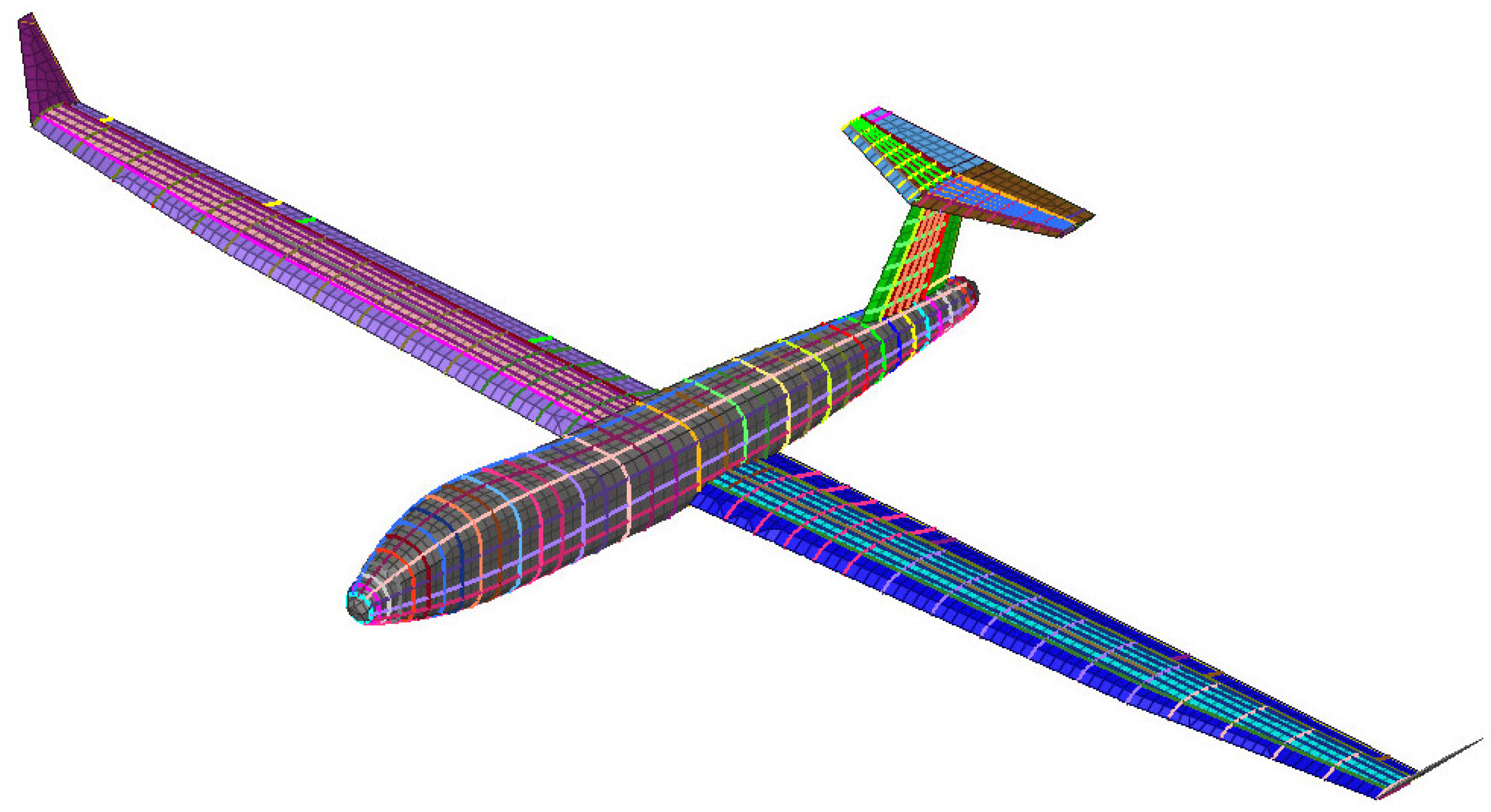
As an example of the problems that might arise without appropriately treating local areas, we apply MDO to the model represented in
Figure 20. As shown in
Figure 21, the right wing of the model presents a non-regular area, highlighted in yellow (
Figure 21c). The part represents a cut-out in the lower-skin of the wing. Cut-outs like this are typically found on the lower skin and are known in the industry as manholes or access panels.
4.2.2. Modelling of the Non-Regular Area
In the global model, the non-regular area shown in
Figure 21d is represented following a smeared stiffness approach, which greatly reduces the number of elements, but does not permit exactly representing the stiffness of the part, nor accurately capturing the internal displacement field. When separately modelled in detail, the part appears as in
Figure 22.
4.2.3. Optimisation and Subsequent Detailed Analysis
Using the simplified modelling of the part, the aeroplane is optimised, keeping the design of the non-regular area fixed without applying any constraint to it. After the MDO procedure is concluded and the design has been optimised, the non-regular area is separately designed in detail and analysed by enforcing at the boundaries the displacements from the aircraft model.
4.2.4. Constraint Violation
As the detailed model of the non-regular area is created and the part is analysed, a violation of the local axial strain constraints is revealed.
Figure 23 shows the maximum composite strain at the beginning of the optimisation, i.e., after 7 iterations (
Figure 23a), and at the end of the optimisation, i.e., after 331 iterations, (
Figure 23b).
If the strain is measured close to the hole but avoids the elements directly linked to the edge where the strain concentration occurs, after 7 iterations, all measures are below the allowable value of
. This can be seen in
Figure 23a and also from the data in
Table 2. This means that the local area was initially sized correctly to sustain the loads at the beginning of the optimisation.
Nevertheless, as the optimisation reaches the optimum, the local values of strain exceed the allowable value.
Table 2 reports the reserve factors (RFs) after 7 iterations and at convergence for the elements highlighted in
Figure 23 and highlights the violated constraints:
4.2.5. On the Importance of Considering Local Sizing during Global MDO
This example shows that excluding non-regular areas from the optimisation and leaving them unconstrained can lead to a significant and unpredictable drop of the reserve factors, even if the local area was initially correctly sized.
This problem may be solved by sizing the local part, but modifying the local stiffness and mass can dramatically alter the loadpaths of the entire structure and potentially invalidate the design obtained by MDO. This is typical of non-regular areas like the one presented, especially in the case of a sequence of similar cut-outs along the wing span. Thus, local constraint violations like these, only discovered at a later stage, may force the designers to repeat a multidisciplinary optimisation and therefore result in a costly setback.
5. Conclusions
In this paper, we presented a systematic review of the state-of-the-art research in Multidisciplinary Design Optimisation (MDO) and global–local optimisation methods, mainly focusing on the application of airframe sizing in the aerospace industry. Moreover, we presented the current industry practice in airframe sizing and its limitations. In particular, we gave a detailed account of why it is desirable to consider the influence of non-regular areas, on the sizing of primary structures, and of what might be the consequences of neglecting them. As explained in the previous section, the main limitations of the approach described are caused by:
Inaccurate weight and stiffness estimations,
The fact that non-regular areas are kept fixed during the optimisation,
The lack of constraints defined over the non-regular areas.
Including them directly as a local refinement would allow the optimisation and definition of constraints while guaranteeing a correct evaluation of weight and stiffness. Nevertheless, this is not a viable solution because the non-regular parts require a detailed modelling, and an approach like that would result in a prohibitive computational cost of the MDO procedure.
The benefits that come from the early adoption of MDO as a design tool may be compromised if the analysis and sizing of non-regular areas are neglected. We presented the case for integrating the design of these parts in the MDO procedure. In particular, we have shown that keeping local areas fixed and unconstrained or wrongly estimating their properties may lead to:
A wrong performance assessment, which affects the choice of the best design concept;
A non-optimal design;
or
Constraint violations, both of which may force to repeat the MDO process and cause costly delays.
A solution must enhance the current procedure with some information from the detailed modelling of non-regular areas while containing the overall computational cost. To this end, one can exploit the following facts:
The MDO procedure only requires detailed information about weight and stiffness,
Detailed FE-models are mainly needed to evaluate constraint violations within non-regular areas for which not all disciplines must be solved.
Future work will define, implement and test a procedure designed to take advantage of these facts. Lastly, the additional computational cost will have to be measured and weighted against the expected advantages.
Author Contributions
Conceptualisation, M.S. and J.N.; methodology, M.S., F.G. and F.D.; formal analysis, M.S.; writing—original draft preparation, M.S.; writing—review and editing, J.N., D.C., F.G.; supervision, J.N., D.C., F.G. and F.D.; project administration, J.N.; funding acquisition, D.C. All authors have read and agreed to the published version of the manuscript.
Funding
This project has received funding from the European Union’s Horizon 2020 research and innovation programme under the Marie Skłodowska-Curie grant agreement No 764650.
Institutional Review Board Statement
Not applicable.
Informed Consent Statement
Not applicable.
Data Availability Statement
Not applicable.
Conflicts of Interest
The authors declare no conflict of interest. The funders had no role in the design of the study; in the collection, analyses, or interpretation of data; in the writing of the manuscript, or in the decision to publish the results.
Abbreviations
| MDO | Multidisciplinary Design Optimisation |
| MDA | Multidisciplinary Analysis |
| CA | Contributing Analysis |
| MDF | Multidisciplinary Feasible |
| IDF | Individual Discipline Feasible |
| AAO | All-At-Once |
| SAND | Simultaneous Analysis and Design |
| CSSO | Concurrent Subspace Optimisation |
| GSE | Global Sensitivity Equation |
| BLISS | Bilevel Integrated System Synthesis |
| CO | Collaborative Optimisation |
| ECO | Extended Collaborative Optimisation |
| QSP | Quasi-Separable Problems |
| QSD | Quasi-Separable Decomposition |
| ATC | Analytical Target Cascading |
| GFEM | Global Finite Element Model |
| DFEM | Detailed Finite Element Model |
| FE | Finite Element |
| CLT | Classical Laminate Theory |
| PSO | Particle Swarm Optimisation |
References
- Taylor, R.; Garcia, J.; Tang, P.S. Using Optimization for Structural Analysis Productivity Improvement on the F-35 Lightning II. In Proceedings of the 48th AIAA/ASME/ASCE/AHS/ASC Structures, Structural Dynamics, and Materials Conference, Honolulu, HI, USA, 23–26 April 2007. [Google Scholar] [CrossRef]
- Ullman, D.G. The Mechanical Design Process, 4th ed.; McGraw-Hill Series in Mechanical Engineering; McGraw-Hill Higher Education: Boston, MA, USA, 2010. [Google Scholar]
- Schuhmacher, G.; Daoud, F.; Petersson, O.; Wagner, M.; Straße, R.; Schuhmacher, G.; Petersson, O. Multidisciplinary airframe design optimisation. In Proceedings of the 28th Congress of the International Council of the Aeronautical Sciences (ICAS), Brisbane, Australia, 23–28 September 2012; Available online: http://www.icas.org/ICAS_ARCHIVE/ICAS2012/PAPERS/994.PDF (accessed on 5 August 2021).
- Sobieszczanski-Sobieski, J.B. Aerospace engineering design by systematic decomposition and multilevel optimization. In Proceedings of the Congress of the International Council of the Aeronautical Sciences (ICAS), Toulouse, France, 10–14 September 1984. [Google Scholar]
- Martins, J.R.R.A.; Lambe, A.B. Multidisciplinary Design Optimization: A Survey of Architectures. AIAA J. 2013, 51, 2049–2075. [Google Scholar] [CrossRef] [Green Version]
- Cramer, E.J.; Frank, P.D.; Shubin, G.R.; Dennis, J.E.; Lewis, R.M. On Alternative Problem Formulations for Multidisciplinary Design Optimization. In Proceedings of the 4th Symposium on Multidisciplinary Analysis and Optimization, Cleveland, OH, USA, 21–23 September 1992. [Google Scholar] [CrossRef] [Green Version]
- Cramer, E.; Dennis, J.E.; Frank, P.; Lewis, R.; Shubin, G. Problem Formulation for Multidisciplinary Optimization. SIAM J. Optim. 1994, 4, 754–776. [Google Scholar] [CrossRef]
- Haftka, R.T. Simultaneous analysis and design. AIAA J. 1985, 23, 1099–1103. [Google Scholar] [CrossRef]
- Sobieszczanski-Sobieski, J.; James, B.B.; Dovi, A.R. Structural optimization by multilevel decomposition. AIAA J. 1985, 23, 1775–1782. [Google Scholar] [CrossRef]
- Sobieszczanski-Sobieski, J.; James, B.B.; Riley, M.F. Structural sizing by generalized, multilevel optimization. AIAA J. 1987, 25, 139–145. [Google Scholar] [CrossRef]
- Sobieszczanski-Sobieski, J. Optimization by Decomposition: A Step from Hierarchic to Non-Hierarchic Systems; National Aeronautics and Space Administration, Langley Research Center: Hampton, VA, USA, 1988. [Google Scholar]
- Bloebaum, C.L.; Hajela, P.; Sobieszczanski-Sobieski, J. Non-Hierarchic System Decomposition in Structural Optimization. Eng. Optim. 1992, 19, 171–186. [Google Scholar] [CrossRef]
- Sobieszczanski-Sobieski, J. Sensitivity of complex, internally coupled systems. AIAA J. 1990, 28, 153–160. [Google Scholar] [CrossRef]
- Haftka, R.T.; Sobieszczanski-Sobieski, J.; Padula, S.L. On options for interdisciplinary analysis and design optimization. Struct. Optim. 1992, 4, 65–74. [Google Scholar] [CrossRef]
- Sobieszczanski-Sobieski, J.; Agte, J.; Robert Sandusky, J. Bi-level integrated system synthesis (BLISS). In Proceedings of the 7th AIAA/USAF/NASA/ISSMO Symposium on Multidisciplinary Analysis and Optimization, St. Louis, MO, USA, 2–4 September 1998; American Institute of Aeronautics and Astronautics: Reno, NV, USA, 1998. [Google Scholar] [CrossRef] [Green Version]
- Braun, R.D.; Kroo, I.M. Development and Application of the Collaborative Optimization Architecture in a Multidisciplinary Design Environment; NASA Langley Research Center: Hampton, VA, USA, 1995; p. 19. [Google Scholar]
- Braun, R.D. Collaborative Optimization: An Architecture for Large-Scale Distributed Design. Ph.D. Thesis, Stanford University, Stanford, CA, USA, 1996. [Google Scholar]
- Roth, B.D.; Kroo, I.M. Enhanced Collaborative Optimization: Application to an Analytic Test Problem and Aircraft Design. In Proceedings of the 12th AIAA/ISSMO Multidisciplinary Analysis and Optimization Conference, Victoria, BC, Canada, 10–12 September 2008. [Google Scholar] [CrossRef] [Green Version]
- Roth, B.D.; Kroo, I.M. Enhanced Collaborative Optimization: A Decomposition-Based Method for Multidisciplinary Design. In Proceedings of the ASME 2008 International Design Engineering Technical Conferences and Computers and Information in Engineering Conference, Brooklyn, NY, USA, 3–6 August 2008; American Society of Mechanical Engineers Digital Collection: Reno, NV, USA, 2009; pp. 927–936. [Google Scholar] [CrossRef] [Green Version]
- Haftka, R.T.; Watson, L.T. Multidisciplinary Design Optimization with Quasiseparable Subsystems. Optim. Eng. 2005, 6, 9–20. [Google Scholar] [CrossRef]
- Haftka, R.T.; Watson, L.T. Decomposition theory for multidisciplinary design optimization problems with mixed integer quasiseparable subsystems. Optim. Eng. 2006, 7, 135–149. [Google Scholar] [CrossRef]
- Michelena, N.; Kim, H.; Papalambros, P. A System Partitioning and Optimization Approach to Target Cascading. In Proceedings of the International Conference on Engineering Design (ICED 99), Munich, Germany, 24–26 August 1999; Available online: https://www.researchgate.net/publication/2319317_A_System_Partitioning_And_Optimization_Approach_To_Target_Cascading (accessed on 5 August 2021).
- Kim, H.M.; Michelena, N.F.; Papalambros, P.Y.; Jiang, T. Target Cascading in Optimal System Design. J. Mech. Des. 2003, 125, 474–480. [Google Scholar] [CrossRef]
- Michelena, N.; Park, H.; Papalambros, P.Y. Convergence Properties of Analytical Target Cascading. AIAA J. 2003, 41, 897–905. [Google Scholar] [CrossRef]
- Kim, H.; Kokkolaras, M.; Louca, L.; Delagrammatikas, G.; Michelena, N.; Filipi, Z.; Papalambros, P.; Assanis, D. Target Cascading in Vehicle Redesign: A Class VI Truck Study. Int. J. Veh. Des. 2002, 29, 199–225. [Google Scholar] [CrossRef]
- Kim, H.M.; Rideout, D.G.; Papalambros, P.Y.; Stein, J.L. Analytical Target Cascading in Automotive Vehicle Design. J. Mech. Des. 2003, 125, 481–489. [Google Scholar] [CrossRef] [Green Version]
- Tosserams, S.; Etman, L.F.P.; Papalambros, P.Y.; Rooda, J.E. An augmented Lagrangian relaxation for analytical target cascading using the alternating direction method of multipliers. Struct. Multidisc. Optim. 2006, 31, 176–189. [Google Scholar] [CrossRef] [Green Version]
- Tosserams, S.; Etman, L.F.P.; Rooda, J.E. An augmented Lagrangian decomposition method for quasi-separable problems in MDO. Struct. Multidisc. Optim. 2007, 34, 211–227. [Google Scholar] [CrossRef] [Green Version]
- Tosserams, S.; Etman, L.F.P.; Rooda, J.E. Augmented Lagrangian coordination for distributed optimal design in MDO. Int. J. Numer. Methods Eng. 2008, 73, 1885–1910. [Google Scholar] [CrossRef] [Green Version]
- Sellar, R.; Batill, S.; Renaud, J. Response surface based, concurrent subspace optimization for multidisciplinary system design. In Proceedings of the 34th Aerospace Sciences Meeting and Exhibit, Reno, NV, USA, 15–18 January 1996. [Google Scholar] [CrossRef] [Green Version]
- Kodiyalam, S.; Sobieszczanski-Sobieski, J. Bilevel Integrated System Synthesis with Response Surfaces. AIAA J. 2000, 38, 1479–1485. [Google Scholar] [CrossRef]
- Sobieski, I.P.; Kroo, I.M. Collaborative Optimization Using Response Surface Estimation. AIAA J. 2000, 38, 1931–1938. [Google Scholar] [CrossRef]
- Liu, B.; Haftka, R.; Watson, L. Global-local structural optimization using response surfaces of local optimization margins. Struct. Multidisc. Optim. 2004, 27, 352–359. [Google Scholar] [CrossRef] [Green Version]
- Vanaret, C.; Gallard, F. On the Consequences of the “No Free Lunch” Theorem for Optimization on the Choice of MDO Architecture. In Proceedings of the 18th AIAA/ISSMO Multidisciplinary Analysis and Optimization Conference, Denver, CO, USA, 5–9 June 2017; Available online: https://www.researchgate.net/publication/316847254_On_the_Consequences_of_the_No_Free_Lunch_Theorem_for_Optimization_on_the_Choice_of_MDO_Architecture (accessed on 5 August 2021).
- Tedford, N.; Martins, J.R.R.A. On the Common Structure of MDO Problems: A Comparison of Architectures. In Proceedings of the 11th AIAA/ISSMO Multidisciplinary Analysis and Optimization Conference, Portsmouth, VA, USA, 6–8 September 2006; American Institute of Aeronautics and Astronautics: Reno, NV, USA, 2006. [Google Scholar] [CrossRef]
- Martins, J.; Marriage, C.; Tedford, N. pyMDO: An Object-Oriented Framework for Multidisciplinary Design Optimization. ACM Trans. Math. Softw. 2009, 36, 1–25. [Google Scholar] [CrossRef]
- Tedford, N.P.; Martins, J.R.R.A. Benchmarking multidisciplinary design optimization algorithms. Optim. Eng. 2010, 11, 159–183. [Google Scholar] [CrossRef] [Green Version]
- Gray, J.; Moore, K.; Naylor, B. OpenMDAO: An Open Source Framework for Multidisciplinary Analysis and Optimization. In Proceedings of the 13th AIAA/ISSMO Multidisciplinary Analysis Optimization Conference, Fort Worth, TX, USA, 13–15 September 2010; American Institute of Aeronautics and Astronautics: Reno, NV, USA, 2010. [Google Scholar] [CrossRef] [Green Version]
- Gray, J.S.; Hwang, J.T.; Martins, J.R.R.A.; Moore, K.T.; Naylor, B.A. OpenMDAO: An open-source framework for multidisciplinary design, analysis, and optimization. Struct. Multidisc. Optim. 2019, 59, 1075–1104. [Google Scholar] [CrossRef]
- Gallard, F.; Vanaret, C.; Guénot, D.; Gachelin, V.; Lafage, R.; Pauwels, B.; Barjhoux, P.J.; Gazaix, A. GEMS: A Python Library for Automation of Multidisciplinary Design Optimization Process Generation. In Proceedings of the 2018 AIAA/ASCE/AHS/ASC Structures, Structural Dynamics, and Materials Conference, Kissimmee, FL, USA, 8–12 January 2018. [Google Scholar] [CrossRef] [Green Version]
- Gallard, F.; Barjhoux, P.J.; Olivanti, R.; Gazaix, A. GEMS, a Generic Engine for MDO Scenarios: Key Features in Application. In Proceedings of the AIAA Aviation 2019 Forum, Dallas, TX, USA, 17–21 June 2019. [Google Scholar] [CrossRef]
- Ciampa, P.D.; Nagel, B.; Tooren, M. Global Local Structural Optimization of Transportation Aircraft Wings. In Proceedings of the 51st AIAA/ASME/ASCE/AHS/ASC Structures, Structural Dynamics, and Materials Conference, Orlando, FL, USA, 12–15 April 2010; American Institute of Aeronautics and Astronautics: Reno, NV, USA, 2010. [Google Scholar] [CrossRef] [Green Version]
- Noevere, A.T.; Wilhite, A.W. Bi-Level Optimization of a Conceptual Metallic Wing Box with Stiffness Constraints. In Proceedings of the 57th AIAA/ASCE/AHS/ASC Structures, Structural Dynamics, and Materials Conference, San Diego, CA, USA, 4–8 January 2016; American Institute of Aeronautics and Astronautics: Reno, NV, USA, 2016. [Google Scholar] [CrossRef]
- Locatelli, D.; Tamijani, A.Y.; Mulani, S.B.; Liu, Q.; Kapania, R.K. Multidisciplinary Optimization of Supersonic Wing Structures Using Curvilinear Spars and Ribs (SpaRibs). In Proceedings of the 54th AIAA/ASME/ASCE/AHS/ASC Structures, Structural Dynamics, and Materials Conference, Boston, MA, USA, 8–11 April 2013; American Institute of Aeronautics and Astronautics: Reno, NV, USA, 2013. Available online: https://arc.aiaa.org/doi/pdf/10.2514/6.2013-1931 (accessed on 5 August 2021). [CrossRef]
- Liu, Q.; Mulani, S.B.; Kapania, R.K. Global/Local Multidisciplinary Design Optimization of Subsonic Wing. In Proceedings of the 10th AIAA Multidisciplinary Design Optimization Conference, National Harbor, MD, USA, 13–17 January 2014; AIAA SciTech Forum, American Institute of Aeronautics and Astronautics: Reno, NV, USA, 2014. [Google Scholar] [CrossRef]
- Liu, Q.; Jrad, M.; Mulani, S.B.; Kapania, R.K. Integrated Global Wing and Local Panel Optimization of Aircraft Wing. In Proceedings of the 56th AIAA/ASCE/AHS/ASC Structures, Structural Dynamics, and Materials Conference, Kissimmee, FL, USA, 5–9 January 2015; American Institute of Aeronautics and Astronautics: Reno, NV, USA, 2015. [Google Scholar] [CrossRef]
- Liu, Q.; Jrad, M.; Mulani, S.B.; Kapania, R.K. Global/Local Optimization of Aircraft Wing Using Parallel Processing. AIAA J. 2016, 54, 3338–3348. [Google Scholar] [CrossRef]
- Robinson, J.; Doyle, S.; Ogawa, G.; Baker, M.; De, S.; Jrad, M.; Kapania, R. Aeroservoelastic Optimization of Wing Structure Using Curvilinear Spars and Ribs (SpaRibs). In Proceedings of the 17th AIAA/ISSMO Multidisciplinary Analysis and Optimization Conference, Washington, DC, USA, 13–17 June 2016. [Google Scholar] [CrossRef]
- Mulani, S.B.; Slemp, W.C.H.; Kapania, R.K. EBF3PanelOpt: An optimization framework for curvilinear blade-stiffened panels. Thin-Walled Struct. 2013, 63, 13–26. [Google Scholar] [CrossRef]
- Jrad, M.; De, S.; Kapania, R.K. Global-local Aeroelastic Optimization of Internal Structure of Transport Aircraft wing. In Proceedings of the 18th AIAA/ISSMO Multidisciplinary Analysis and Optimization Conference, Denver, CO, USA, 5–9 June 2017; American Institute of Aeronautics and Astronautics: Reno, NV, USA, 2017. [Google Scholar] [CrossRef]
- Zhao, W.; Kapania, R.K. Bilevel Programming Weight Minimization of Composite Flying-Wing Aircraft with Curvilinear Spars and Ribs. AIAA J. 2019, 57, 2594–2608. [Google Scholar] [CrossRef]
- Stanford, B.K.; Jutte, C.V.; Coker, C.A. Aeroelastic Sizing and Layout Design of a Wingbox Through Nested Optimization. AIAA J. 2019, 57, 848–857. [Google Scholar] [CrossRef]
- Stanford, B. Shape, sizing, and topology design of a wingbox under aeroelastic constraints. In Proceedings of the AIAA AVIATION 2020 FORUM, online. 15–19 June 2020; American Institute of Aeronautics and Astronautics: Reston, VA, USA, 2020; Volume 1, pp. 1–11. [Google Scholar] [CrossRef]
- Liu, B.; Haftka, R.; Akgün, M. Two-level composite wing structural optimization using response surfaces. Struct. Multidisc. Optim. 2000, 20, 87–96. [Google Scholar] [CrossRef]
- Elham, A.; van Tooren, M.J.L.; Sobieszczanski-Sobieski, J. Bilevel Optimization Strategy for Aircraft Wing Design Using Parallel Computing. AIAA J. 2014, 52, 1770–1783. [Google Scholar] [CrossRef]
- Ragon, S.; Gurdal, Z.; Haftka, R.; Tzong, T.; Ragon, S.; Gurdal, Z.; Haftka, R.; Tzong, T. Global/local structural wing design using response surface techniques. In Proceedings of the 38th Structures, Structural Dynamics, and Materials Conference, Kissimmee, FL, USA, 7–10 April 1997; American Institute of Aeronautics and Astronautics: Reno, NV, USA, 1997. [Google Scholar] [CrossRef]
- Ragon, S.A.; Gürdal, Z.; Haftka, R.T.; Tzong, T.J. Bilevel Design of a Wing Structure Using Response Surfaces. J. Aircr. 2003, 40, 985–992. [Google Scholar] [CrossRef]
- Raymer, D. Aircraft Design: A Conceptual Approach, 6th ed.; American Institute of Aeronautics and Astronautics: Washington, DC, USA, 2018. [Google Scholar] [CrossRef] [Green Version]
Figure 1.
Setbacks are normal in product development, but their opportunity cost increases as the design progresses, which leads to the design paradox. (a) Product development is characterised by steps forward and setbacks due to the violation of design requirements. (b) The design paradox: as designers gain knowledge on how to design the product, they lose the freedom to modify the design.
Figure 2.
Structure of an MDO problem.
Figure 2.
Structure of an MDO problem.
Figure 3.
A contributing analysis (i) modelled as a system, receiving input from another CA (j).
Figure 3.
A contributing analysis (i) modelled as a system, receiving input from another CA (j).
Figure 4.
An MDA with 3 interacting CAs.
Figure 4.
An MDA with 3 interacting CAs.
Figure 5.
A contributing analysis (i) modelled in detail, receiving input from another CA (j).
Figure 5.
A contributing analysis (i) modelled in detail, receiving input from another CA (j).
Figure 6.
Overview of the optimisation procedure.
Figure 6.
Overview of the optimisation procedure.
Figure 7.
Flowchart of multidisciplinary feasible architecture: detail of the analysis block from
Figure 6.
Figure 7.
Flowchart of multidisciplinary feasible architecture: detail of the analysis block from
Figure 6.
Figure 8.
A coupling variable is substituted by a response–target and consistency constraint.
Figure 8.
A coupling variable is substituted by a response–target and consistency constraint.
Figure 9.
Flowchart of the individual discipline feasibility architecture: detail of the analysis block from
Figure 6.
Figure 9.
Flowchart of the individual discipline feasibility architecture: detail of the analysis block from
Figure 6.
Figure 10.
Flowchart of the all-at-once architecture: details of the analysis block from
Figure 6.
Figure 10.
Flowchart of the all-at-once architecture: details of the analysis block from
Figure 6.
Figure 11.
Comparison between a monolithic (left) and a distributed architecture (right).
Figure 11.
Comparison between a monolithic (left) and a distributed architecture (right).
Figure 12.
A response surface can be used to decouple a two-level architecture. (a) Two-level architecture, with a nested optimisation loop. (b) A response surface (RSM) can be substituted for the nested procedure. The RSM can be created and updated in parallel, effectively decoupling the two optimisation procedures.
Figure 13.
The design phases and the use of MDO.
Figure 13.
The design phases and the use of MDO.
Figure 14.
Examples of non-regular areas.
Figure 14.
Examples of non-regular areas.
Figure 15.
Wrong assessment of the configuration performance.
Figure 15.
Wrong assessment of the configuration performance.
Figure 16.
Consequences of an inaccurate representation of the optimisation problem. (a) Optimisation problem solved by the MDO procedure; (b) Suboptimal solution: when accurately represented, the objective is different; (c) Invalid solution: when accurately represented, the constraints are different.
Figure 17.
Inaccurate representation of the global optimisation problem.
Figure 17.
Inaccurate representation of the global optimisation problem.
Figure 18.
Undetected local constraint violations.
Figure 18.
Undetected local constraint violations.
Figure 19.
Sub-optimal overall design.
Figure 19.
Sub-optimal overall design.
Figure 20.
Finite element model of OptiMALE.
Figure 20.
Finite element model of OptiMALE.
Figure 21.
Non-regular area (in yellow) as represented in the aircraft model. (a) OptiMALE with the wing upper-skin removed; (b) Zoom on the right wing (upper-skin removed); (c) Zoom on the non-regular area (in yellow); (d) Zoom on the non-regular area with surrounding spars and ribs removed.
Figure 21.
Non-regular area (in yellow) as represented in the aircraft model. (a) OptiMALE with the wing upper-skin removed; (b) Zoom on the right wing (upper-skin removed); (c) Zoom on the non-regular area (in yellow); (d) Zoom on the non-regular area with surrounding spars and ribs removed.
Figure 22.
Detailed representation of the non-regular area.
Figure 22.
Detailed representation of the non-regular area.
Figure 23.
Violation of strain constraints in the local model.
Figure 23.
Violation of strain constraints in the local model.
Table 1.
Comparison of two-level approaches.
Table 1.
Comparison of two-level approaches.
| Two-Level Approaches | Comparison |
|---|
Alternate Global–Local
References: Ciampa et al. [42] |
![Aerospace 08 00223 i001]() | Advantages:
reduced computational cost |
Disadvantage:
not always applicable, possible optimality or convergence issues |
Nested Local
References: Noevere and Wilhite [43], Kapania et al. [44,45,46,47,48,49,50] |
![Aerospace 08 00223 i002]() | Advantages:
accurate and always applicable |
Disadvantages:
computationally expensive |
Nested Response Surface
References: Liu et al. [54], Ragon et al. [56,57] |
![Aerospace 08 00223 i003]() | Advantages:
reduced computational cost |
Disadvantages:
limited to the accuracy of the response surface |
Table 2.
Composite axial strain.
Table 2.
Composite axial strain.
| Element ID | | At 7 Iterations | At Convergence | Drop in RF |
|---|
| Allowable | Actual | RF | Actual | RF |
|---|
| 42403021 | 5.5 | 4.830 | 1.14 | 5.564 | 0.99 | −0.15 |
| 42403023 | 5.5 | 5.002 | 1.10 | 5.757 | 0.96 | −0.14 |
| 42403025 | 5.5 | 5.126 | 1.07 | 5.898 | 0.93 | −0.14 |
| 42403027 | 5.5 | 5.221 | 1.05 | 6.003 | 0.92 | −0.14 |
| 42403189 | 5.5 | 5.247 | 1.05 | 6.030 | 0.91 | −0.14 |
| 42403191 | 5.5 | 5.218 | 1.05 | 5.993 | 0.92 | −0.14 |
| 42403193 | 5.5 | 5.154 | 1.07 | 5.916 | 0.93 | −0.14 |
| 42403195 | 5.5 | 5.031 | 1.09 | 5.772 | 0.95 | −0.14 |
| 42403197 | 5.5 | 4.835 | 1.14 | 5.545 | 0.99 | −0.15 |
| Publisher’s Note: MDPI stays neutral with regard to jurisdictional claims in published maps and institutional affiliations. |
© 2021 by the authors. Licensee MDPI, Basel, Switzerland. This article is an open access article distributed under the terms and conditions of the Creative Commons Attribution (CC BY) license (https://creativecommons.org/licenses/by/4.0/).


 ,
, 


