4.2. Functional Allocation
As already mentioned, KPLO FDS consists of six major functional modules: SMM, ODM, MPM, SPM, FAM, and AM. Each module performs a unique function that is indispensable in supporting the execution of the entire KPLO mission. The unique functions of each module were designed considering the operational characteristics of each mission phase of the KPLO mission.
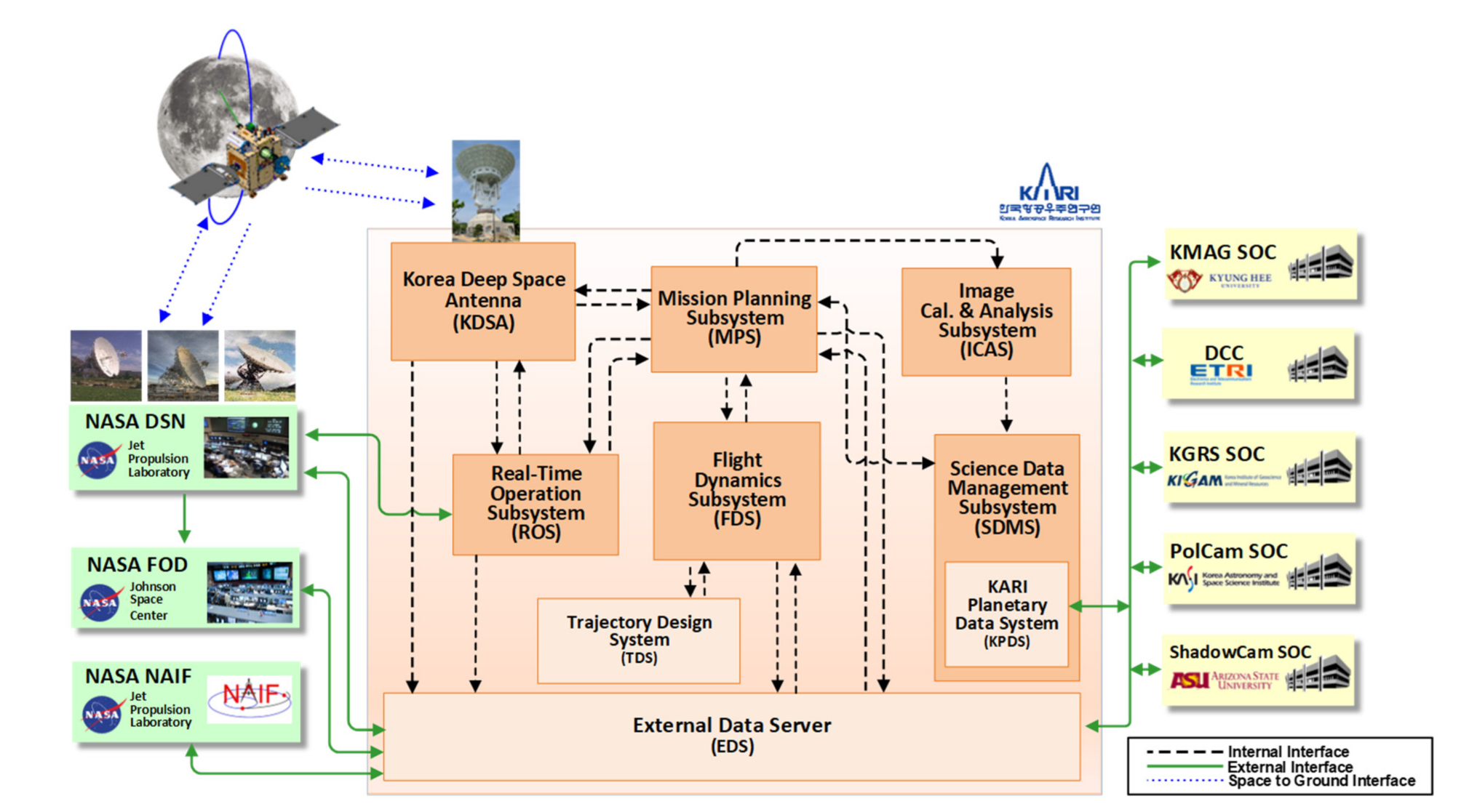
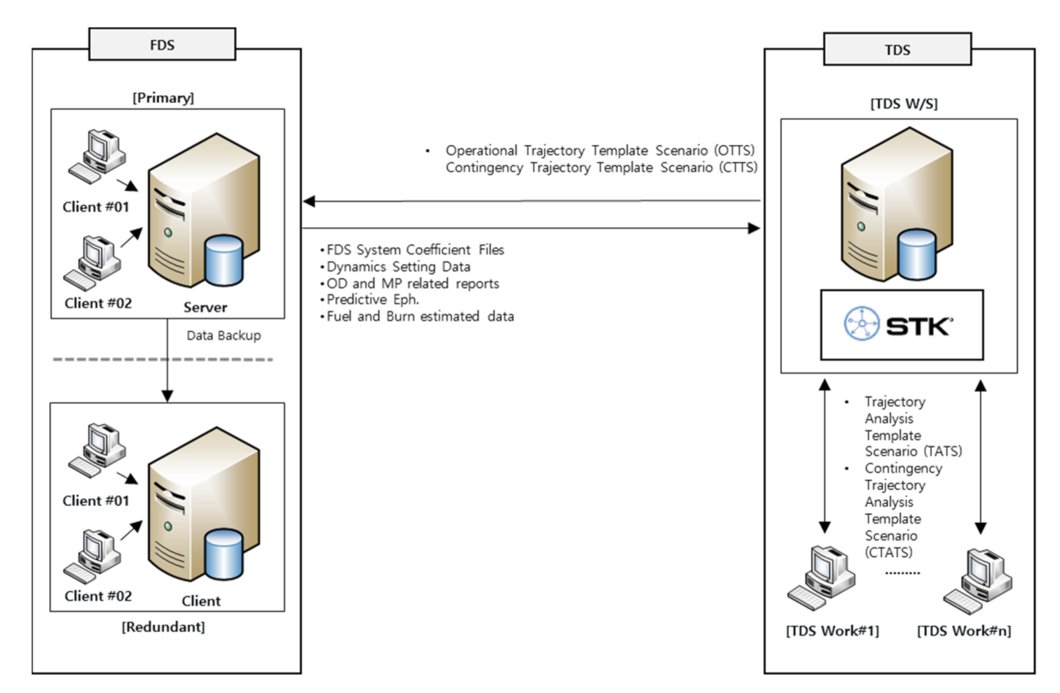
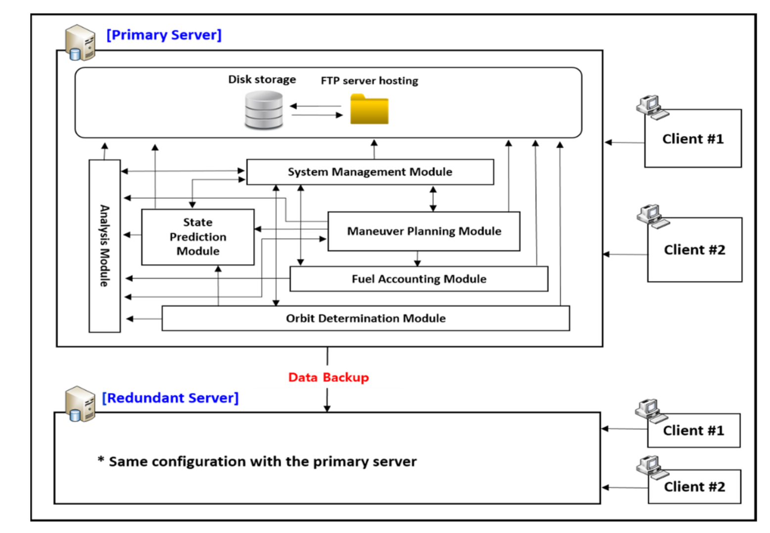
Figure 6 shows the architecture of the functional modules associated with the primary–redundant structure of the KPLO FDS. A summary of the key features for the six modules is shown in
Table 3. In the following subsections, detailed functionalities for each of the six major modules will be described.
4.2.1. System Management Module (SMM)
The SMM module has the main function of systematically managing and setting up the entire FDS system environment. The operator can set up and configure KPLO FDS through SMM. SMM provides a total of five main functions, as follows.
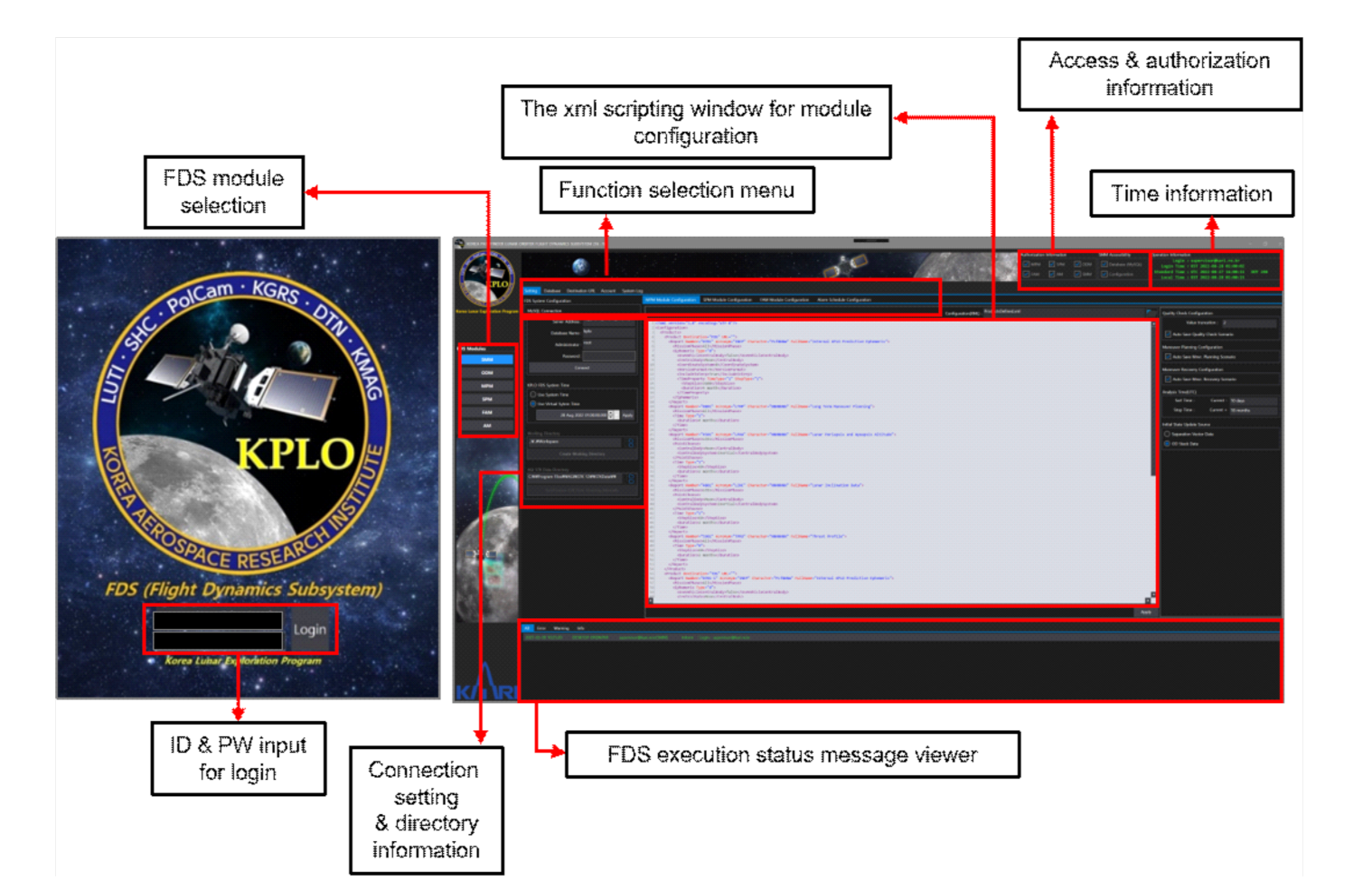
First, the operator can perform the setting for each module of the FDS by using the xml script or via the setting dialog on the screen. As an example of the SPM module configuration through SMM, the generation period, period, and interval of outputs to be generated in the SPM can be defined and registered in advance through an xml script, and related contents can be changed simply by modifying the xml later. Second, under the name of the FDS database, the management of various parameters is performed as follows through SMM. Various parameters include those related to the KPLO bus system, force modeling parameters used for each mission phase, thruster and engine configuration, and tracking station information, etc. Some parameters managed by the FDS database will be updated periodically based on the calculation results of the submodules during FDS operation. Actually, all parameters in the FDS database can essentially be updated during operation, but updates during the operation are limited to being performed only by authorized users. Third, SMM has the function of registering and managing the information of the target destination for the delivery of various products generated in FDS through FTP. Fourth, FDS user information can be registered (ID and PW) and managed through SMM. While registering a user account, each user’s accessibility to the FDS functional module can be limited and granted, depending on each operator’s role and responsibility. Finally, system log management is possible in SMM. The FDS log history can be tracked and searched for certain kinds of tasks, for example, which parameters were changed by each user or period of use, in the FDS. The left side of
Figure 7 shows the first login screen of the KPLO FDS, and the right side shows the main screen of the SMM module.
4.2.2. Orbit Determination Module (ODM)
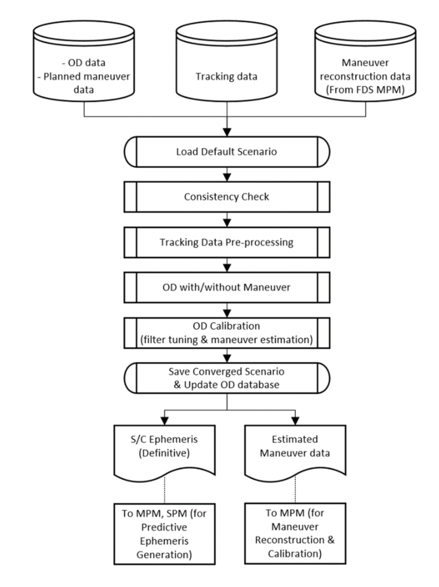
Orbit determination (OD) is a key part of the flight dynamic operation of KPLO. For stable and reliable mission operation, OD and orbit prediction (OP) should be suitably performed by the ODM of the FDS. The ODM has several functions for space navigation, such as initial orbit determination (IOD) for the initial acquisition after separation from the launch vehicle’s upper stage, operational orbit determination (OOD) for translunar and lunar orbit phases, and a maneuver estimation for maneuver reconstruction and calibration. The data generated by ODM are exchanged to the SPM and MPM. FDS ODM employs a scenario-based flow for effective KPLO mission operations, as shown in
Figure 8.
The ODM uses previous orbit stack data, planned maneuver data, tracking data, and maneuver reconstruction data from the FDS database. The first step of the ODM implementation procedure is a loading default template scenario. The prepared scenarios, such as IOD and OOD, can be loaded into a default working directory of FDS ODM. The IOD scenario determines the initial orbit after separation from the launch vehicle’s upper state using ground-based measurements. The OOD scenarios have four different types for different phases: Trans-lunar cruise (TLC), LOA, LOI, and lunar mission. The operator has to select the proper default scenario after checking the mission phase.
After scenario loading, a consistency check is run to compare the parameters used, such as the propagator, spacecraft, and tracking station, to those of the FDS database. A consistency check is a very powerful tool. By automatically confirming the correspondence between the numerous parameters used in the updated template scenario and the parameters currently used in the FDS database, errors due to unexpected parameter settings can be prevented. It is a very useful approach for OD to start using the same parameters of trajectory design and analysis. These parameters can be adjusted during orbit trending, or during the calibration process after the first trial. Then, tracking data preprocessing is accomplished for initializing and editing the tracking files. The KPLO mission mainly employs range and Doppler tracking data from KDSA and NASA DSN for OD. The CCSDS Tracking Data Message (TDM) format is the default for tracking measurements [
44] of FDS ODM. In this procedure, the format of tracking is quickly checked, and abnormal or bad tracking points are edited by the operator. For tracking data preprocessing, the measurement edit tool of FDS AM can also be used before OD processing.
The next step is the OD with or without the maneuver process. In this stage, orbit estimation is performed using a priori state values and preprocessed tracking data. As already discussed, FDS ODM uses AGI ODTK, which employs a sequential estimation technique based on an extended Kalman filter and fixed-point backward smoother. The state estimation process is then iterated until the results satisfy the convergence criteria. A priori state values can be acquired from orbit stack data or a previously determined ephemeris. If maneuvers such as TCM, LOI maneuvers, and the Orbit Maintenance Maneuver (OMM) are included in the OD target period, then maneuver estimation is also performed. Planned maneuver information is then utilized for the initial values of maneuver components. An orbit quality check is also performed in OD with or without a maneuver process step. A post-fit residuals analysis, an error covariance analysis, an orbit overlaps comparison, and an external orbit comparison are considered for the orbit accuracy investigation.
Next, OD calibration via filter tuning for better parameter estimation and maneuver estimation is prepared. Bias calibration and maneuver estimation calibration can be included in the OD calibration. Finally, products of the ODM, such as spacecraft internal definitive ephemeris, OD reports including estimated maneuver data, consistency check reports, OD reports, and orbit stack files, are saved and delivered to other subsystems. Spacecraft definitive ephemeris is delivered to MPM and SPM, and the estimated maneuver data are stored for maneuver recovery and reconstruction.
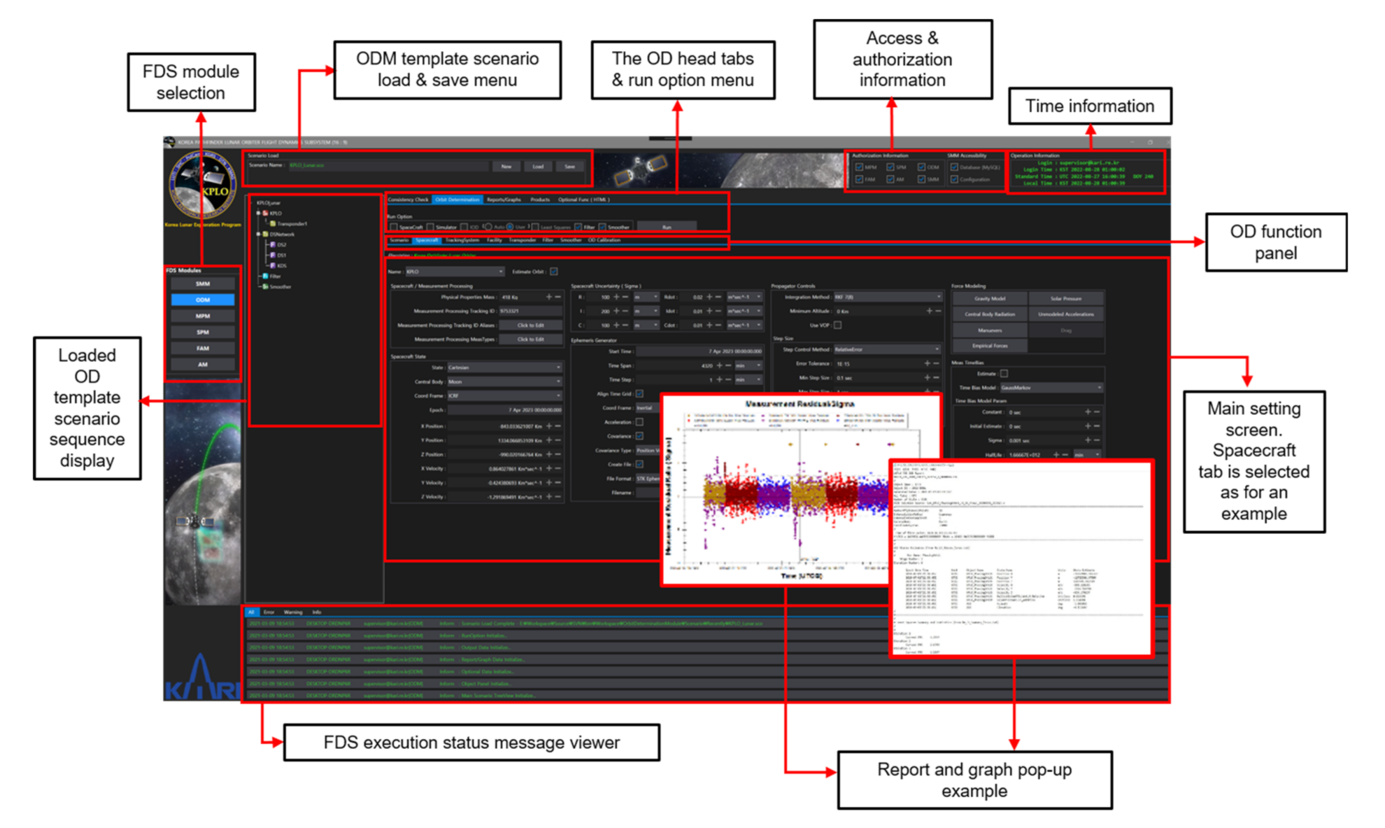
The main screen of the ODM is shown in
Figure 9 as an example with the spacecraft tab selected. The operator can set various spacecraft-related parameters, as well as astrodynamic modeling parameters inside of this spacecraft Table. The pop-up screenshot of the output generated by the ODM is also captured and shown in
Figure 9.
The head tabs are prepared considering the operational OD procedure (a consistency check with the FDS database, run OD, generate reports and graphs, product generation, and some optional functions). The scenario panel, log windows, function panels, and run option checkboxes are included in the main screen of FDS ODM. The function panels consist of various tabs for the execution of OD procedures, such as scenario information, spacecraft setting, tracking system configuration, filtering and smoothing, and OD calibration. The scenario tab displays the information of the loaded scenarios, such as global dynamic modeling parameters, central body, planetary ephemeris, and tracking measurements. The spacecraft tab shows the states, covariance, force modeling, and numerical integration method. The filter and smoother tabs describe the control parameters of sequential estimation. Data editing and maneuver estimation settings are included in this Table. The OD calibration tab is prepared in order to improve the OD results by modifying the force modeling, the initial orbit uncertainty, and the tracker calibration information. Other modeling parameters, such as solar pressure, central body radiation, un-modeled acceleration, air drag, and maneuvers, are also adjusted in the OD calibration Table. The internal spacecraft ephemeris, OD report, consistency check report, and orbit stack files are generated and sent in the products tab.
4.2.3. Maneuver Planning Module (MPM)
The purpose of the MPM is maneuver planning using a detailed thruster configuration to target the desired mission trajectory. The main functions of the MPM are to construct a trajectory utilizing the definitive ephemeris from the ODM, construct a trajectory with a finite burn considering the thruster set, perform a quality check of the maneuver planning result, generate the associated reports and graphs, perform maneuver recovery regarding the executed maneuver, and generate the updated predicted ephemeris for the SPM. The goal of the maneuver planning process is to design, verify, and validate the maneuvers for the maneuver request and the predicted ephemeris generation. In the MPM, it is necessary to perform a consistency check, maneuver planning with a thruster set, a quality check, and product generation sequentially.
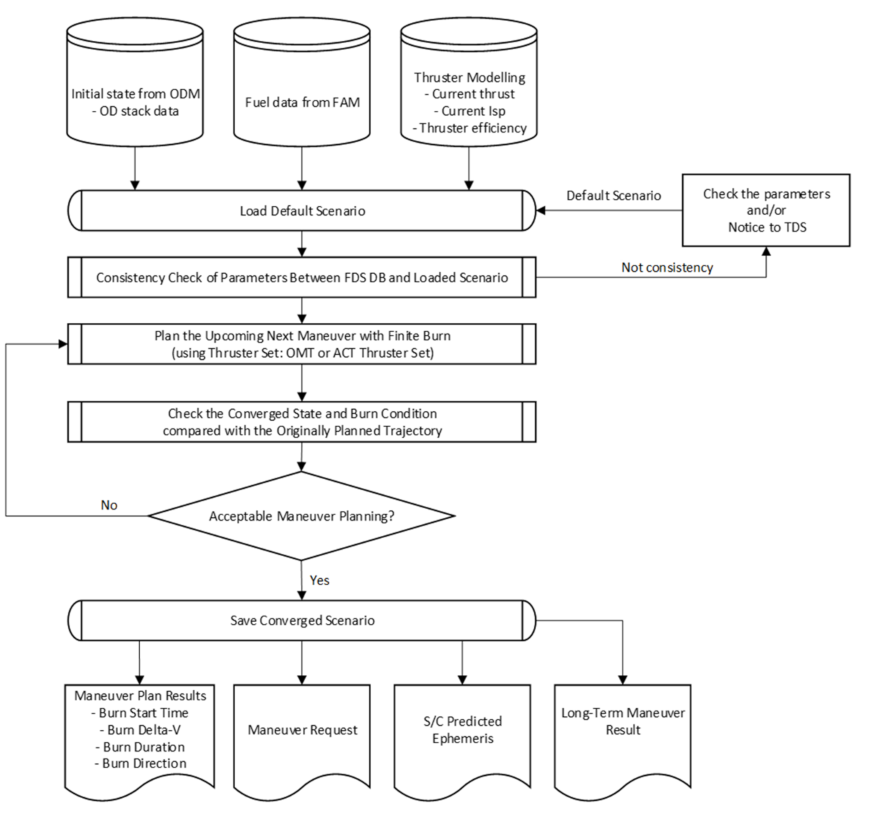
Figure 10 shows the overall workflow of the maneuver planning. First, the updated scenario is delivered from the TDS to the FDS, and is loaded in the MPM with parameters including the propagation, S/C fuel, thrusters, etc. Next, the MPM performs a consistency check to compare those parameters between the loaded scenario and the FDS DB. If the parameters of the loaded scenario are not consistent with those of the FDS DB, the MPM generates and sends the consistency check report to the TDS. After that, the operator can change the updated parameters in the loaded scenario. If those parameters are entirely consistent, then the MPM plans the upcoming next maneuver with the definitive ephemeris from the ODM and the corresponding thruster set with an updated engine model from the FAM. In the MPM, two types of thruster sets are considered with the cant angle: ACT and OMT. This is the baseline for selecting the thruster set according to the maneuver
; the thruster set of ACT will be used for the maneuver with a
below 10 m/s, and the thruster set of OMT is used for the maneuver with a
above 10 m/s. Note that the ACT will be used to maintain attitude control during the OMT burns and to desaturate the reaction wheels. In addition, the ACT will be used as a liquid settling burn before the OMT burn, which can reduce the slosh dynamics during the OMT burn. Therefore, the operator can plan the upcoming next burn by selecting the thruster set according to the maneuver; for example, the LOI maneuver needs more than 600 m/s, and therefore the LOI maneuver will be planned using the thruster set of OMT with a liquid settling burn. The thrust and Isp values of each thruster set are updated in the FAM after the maneuver execution, and those updated values are implemented in the maneuver planning process.
After maneuver planning, the MPM performs a quality check process of the planned upcoming next maneuver. In this process, practical values considering the KPLO bus system are applied to the planned maneuver, such as the burn start time, burn duration, and burn direction. In the current version, the operator can truncate the burn start time in 1 s increments and the burn duration in 0.25 s increments. Moreover, the burn direction is truncated to 2 decimal places, which is described in the azimuth and elevation angles in the Earth International Celestial Reference Frame (ICRF). After modifying those values, we can check and validate the of the remaining maneuvers regarding the total and fuel budget. Finally, the MPM generates the corresponding reports and graphs, including the maneuver request report, the predicted ephemeris, the long-term maneuver planning report, the maneuver setting report, etc. The MPM sends those reports to other modules of the FDS, other KDGS subsystems, and the External Data Server (EDS).
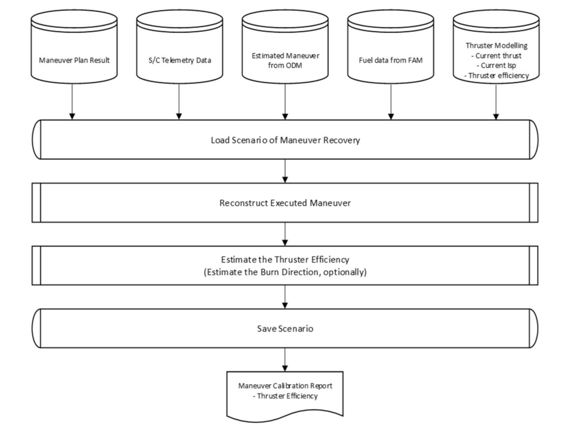
After maneuver execution, the MPM performs the maneuver recovery process. In this process, the executed maneuver is estimated using the telemetry data from the spacecraft.
Figure 11 shows the overall workflow of the maneuver recovery. First, the maneuver recovery scenario is loaded with the maneuver planning report and the maneuver execution telemetry data from the KPLO. Moreover, the definitive ephemeris, including the executed maneuver from the ODM, is loaded. Using those data, the MPM mainly calculates the thrust efficiency and can optionally estimate the burn direction of the executed maneuver. For maneuver recovery, the control parameter and the propagation duration have an effect on the performance of the thrust efficiency estimation. In the KPLO FDS MPM, three types of control parameters are considered: The orbit element difference, the radial, in-track, and cross-track (RIC) component difference, and the position difference. In addition, the MPM prepares to select a propagation duration after the maneuver execution according to the maneuver. For example, the propagation duration can be selected as 3 h and 1 day after maneuver execution, with propagation to the lunar apoapsis. As a result, the MPM generates the corresponding reports and graphs, including the maneuver calibration report. These results are used in the thrust efficiency function of the AM.
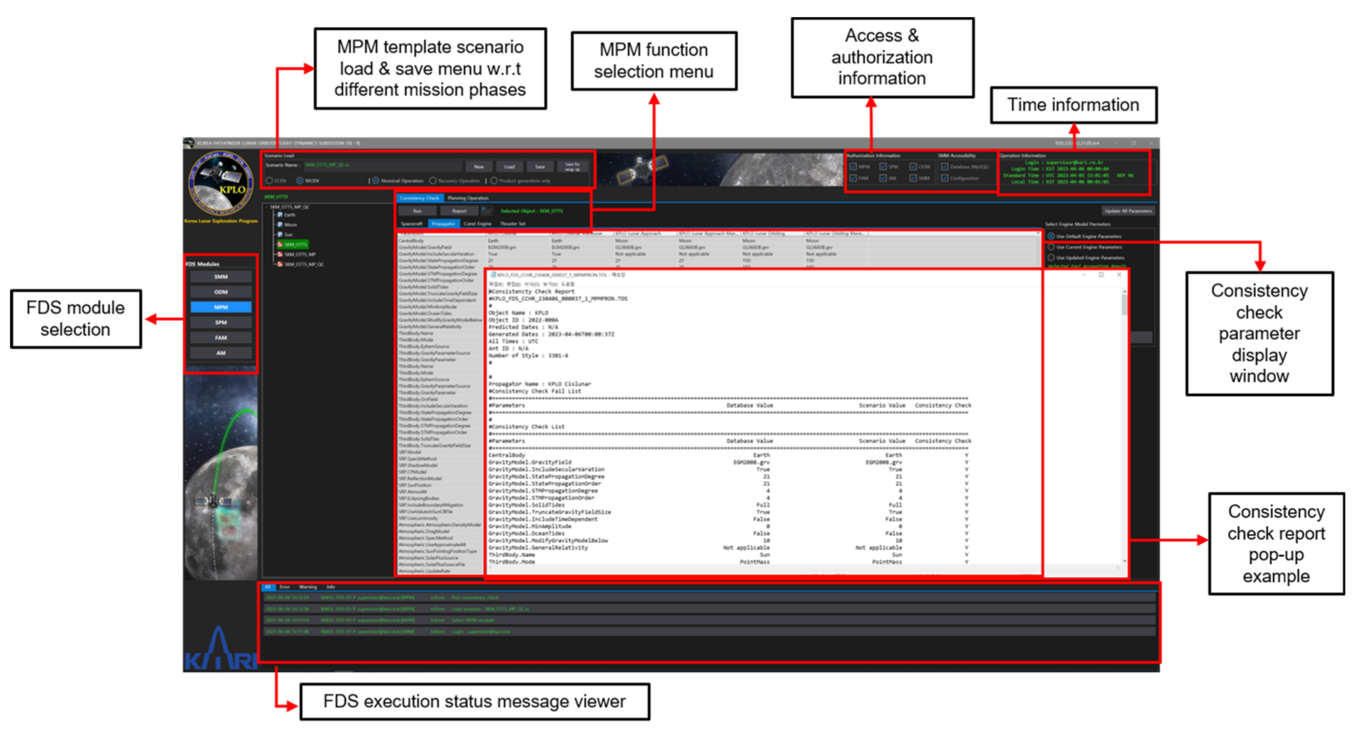
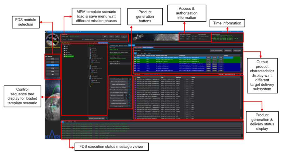
Figure 12 shows the example GUI of the consistency check function and the corresponding report of MPM. When the operator selects the consistency check tab, the parameters between the loaded scenario and the FDS DB are checked before maneuver planning. After completion of the consistency check, the operator can then perform the maneuver planning function. The operator loads the OD stack data as an initial state and selects the proper engine model according to the burn magnitude to perform the maneuver planning. Then, the target sequence is performed in order to match the target values with the finite burn. As a result, the convergence state is shown in the FDS MPM. The predefined products of the maneuver planning are generated, as shown in
Figure 13. The operator can then generate the corresponding reports by selecting the button as shown in the middle of the screen and find them on the right side of the screen. In addition, the operator can generate graphs, such as the lunar inclination and the altitudes of the lunar apoapsis and periapsis, during the mission phase. Those generated reports can be sent to the KDGS subsystems and EDS.
4.2.4. State Prediction Module (SPM)
The main job of the SPM is to predict the states of the KPLO as well as a mission-related trajectory or orbital events and create the related data files. Most FDS products are produced in SPM and delivered to various subsystems. The delivered products are used to operate the KDSA and DSN antennas, establish and operate the operation plan of the bus system, establish and operate the operation plan of the payload, and support postprocessing of the payload scientific data. Generated products will differ concerning different mission phases, such as the Earth-centered phase and the Moon-centered phase, which consists of a late cruise and the start of the commissioning phase. The SPM has the ability to inspect generated products via text editors and graphs and has a function to deliver products requested by other subsystems via FTP. Typical examples of files created by SPM and transferred to other subsystems include predicted and definitive ephemeris, ascending and descending node predicts, mission eclipse predicts, planetary ephemeris including the Sun, Earth, and Moon, ground station view predicts, solar conjunction predicts, station acquisition information, etc. SPM uses predefined template scenarios to generate the major outputs for each mission phase. In addition, in this template scenario, identification IDs are assigned for each product, and a predefined report and graph style for each identification ID is stored in the template scenario. Therefore, SPM can efficiently respond to the creation of various data files requested by different subsystems that have different durations, time intervals, reference frames, generation frequencies, etc. For the KPLO mission, a total of three SPM template scenarios (characterized by the mission phases as described above) have been optimized, configured, and prepared.
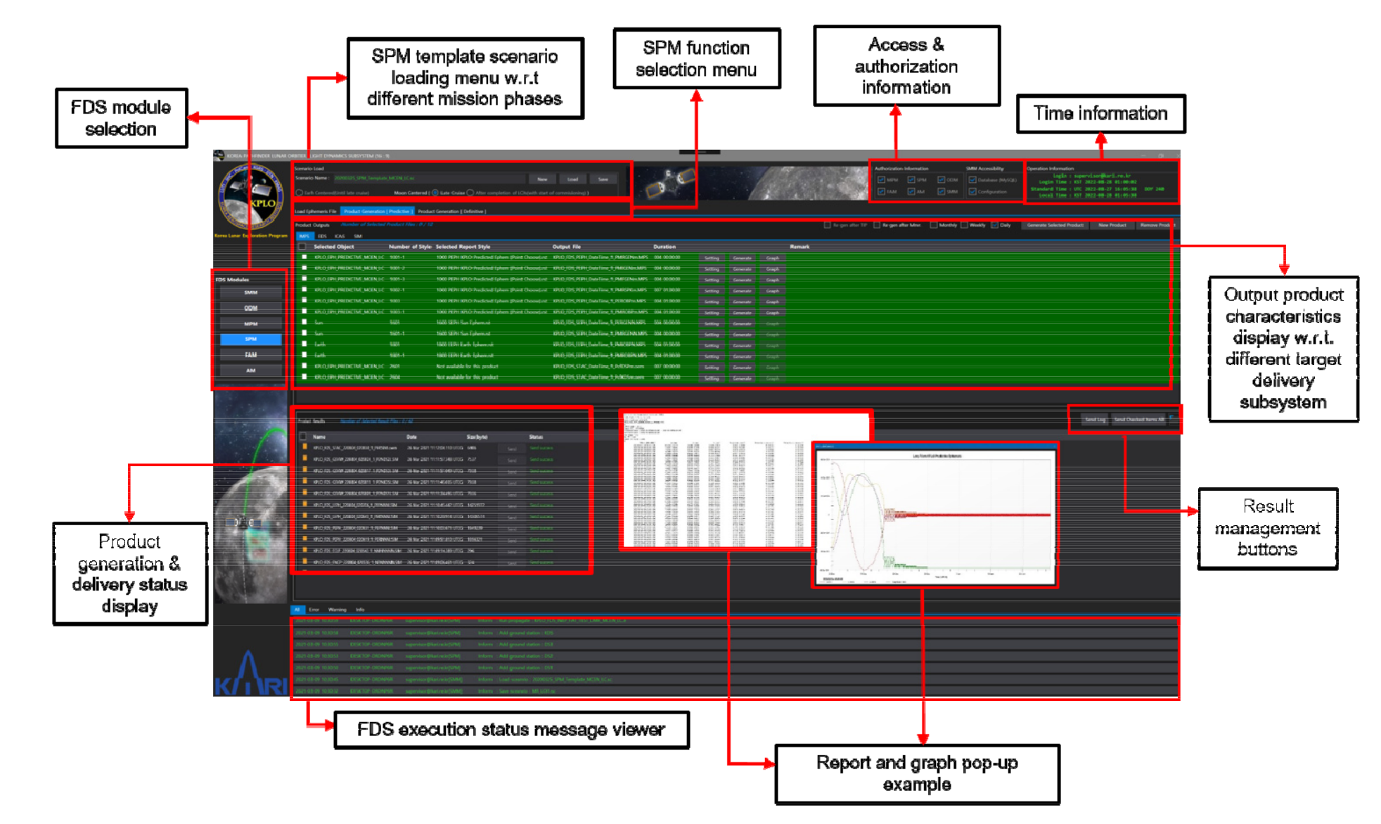
For operator convenience, SPM provides a total of three tabs: Load ephemeris, predictive product generation, and definitive product tabs. The internal ephemeris delivered from MPM and ODM is loaded in the template scenario through the “load ephemeris” Table On the side of the “predictive or definitive product generation” tab, a number of products are generated using predetermined product generation information, that is, the contents managed through xml in the “SPM configuration” tab of SMM. If it is necessary to create an additional product during operation, the operator can simply register the format and identification ID in the template scenario and create the product through xml management in SMM. In addition, if the additional product to be created is the same but only the characteristics of creation are changed, then the attribute can be simply reflected in the xml without registering the report and graph style inside of the template scenario. Most of the products registered and managed through xml in SMM are products that are decided to be regularly generated after sufficient consultation with the target subsystems in advance. In addition to these common functions, SPM also provides a function that allows the operator to produce a product by directly clicking the “new product” button without using the already registered xml. This function is designed to temporarily generate test data at the request of other subsystems in the middle of an operation, and this function was added because those kinds of requests are quite frequent based on the experience of operating several missions in the past. The configuration of the product generated through the “new product” can be modified by the operator from the beginning to the end. After receiving the confirmation of the requested subsystem by using this temporary product, the configuration of those products can be officially registered via xml and can be continuously generated throughout the mission as a regular output product.
After completion of the template scenario loading, the operator can utilize both predictive and definitive product generation tabs, which are divided into two user-friendly screens, “Product output” and “Product result”. In the “Product output” screen, there are sub-tabs named with the target subsystem where the generated products are to be delivered. These sub-tabs are automatically named and linked with the list of target destinations registered in SMM. On the “Product output” screen, information on the selected product ID, report style, file naming convention, etc., is displayed. In addition, when the operator clicks the setting button, the characteristics of the product to be generated (already configured through xml) are summarized and shown, and the operator can generate the product or graph by clicking the generate or graph buttons. Although it is possible to generate each product individually, SPM also provides a function to check the desired product and generate the checked product at once. When an operator produces a product, the generated products are sequentially displayed on the screen below, namely, “Product output”. The operator can reconfirm the products produced on this screen and send them to the target subsystem by pressing the “send” button. At this time, if the transmission is successful, the color of the send button changes to green, and the text is also changed to a send success. Of course, the operator can select multiple products to send, and it also provides a function to send the selected products at once. In addition, SPM provides a function that allows one to search and manage the history of what products were delivered at any time in the past and whether or not the transmission was successful.
Figure 14 shows the GUI of the product generation tab of SPM and shows the graph and output products in text format that are created together during the execution of SPM.
4.2.5. Fuel Accounting Module (FAM)
As the module name indicates, FAM estimates the fuel usage of the KPLO during the operation and generates and delivers the relevant product to other FDS submodules or other subsystems. Because the WSB/BLT method is selected for the KPLO mission, estimating the amount of remaining fuel during the flight is relatively important due to the nature of the WSB/BLT trajectory, which is quite sensitive to the magnitude of imparted . To predict the remaining fuel as accurately as possible, FAM will utilize the pressure, volume, temperature (PVT), and thrust on time (ToT) methods for fuel gauges, as well as related parameter estimation during the flight operation of the KPLO.
As is well known, the PVT method uses the ideal gas law to estimate a fuel volume based on telemetry temperature and pressure, and it has the characteristics that the accuracy of the estimated fuel volume depends on the precision of the propellant tank volume, the pressure, the temperature sensor, helium mass, etc. However, the accuracy of the estimated fuel mass using the PVT method will decrease when the amount of fuel in the tank decreases [
45]. The ToT method, sometimes called the bookkeeping method, relies on the accuracy of the thruster flow rate. Therefore, uncertainty results directly from the uncertainty in the flow rate during engine and thruster firings and thus requires exact knowledge of all thruster on-times and pulse widths and an exact thrust and flow rate through the engines [
45]. To calculate the amount of fuel, the PVT method will be used as the main method. However, to calculate the exact amount of fuel through the PVT method, a settling time longer than a certain period is required. Therefore, the ToT method will be used in parallel and used in FAM. Using ToT, each
component, the total amount, and the start and end times of the maneuvers will be calculated using KPLO telemetry immediately after the maneuver execution. The parameters estimated using the ToT method can be passed to the ODM and will be used as an initial value for the process of performing OD with maneuvers. This may ease the convergence performance of OD that is performed immediately after maneuver execution. To provide more flexibility, FAM is also designed to provide a function to select a standard fuel gauging method, either PVT or ToT, or by the operator. Of course, the operator’s decision on which method to apply will differ for phases of the mission or according to the characteristics of the burn performed. In addition, the operator can type in the current fuel estimates by analyzing past trends in fuel consumption. To perform related functions, FAM provides the function of loading and processing PVT or ToT telemetry, creating related products, analyzing through graphs, and transferring the generated products to other target subsystems through FTP.
Every day, the current fuel mass of the KPLO will be accumulated and recorded in the file and will be transmitted to each subsystem that requires the relevant file. The current fuel mass estimate, Isp, mass flow, and thrust level of each thruster will also be estimated and will be delivered to the FDS database in the SMM to be updated and used for further burn planning.
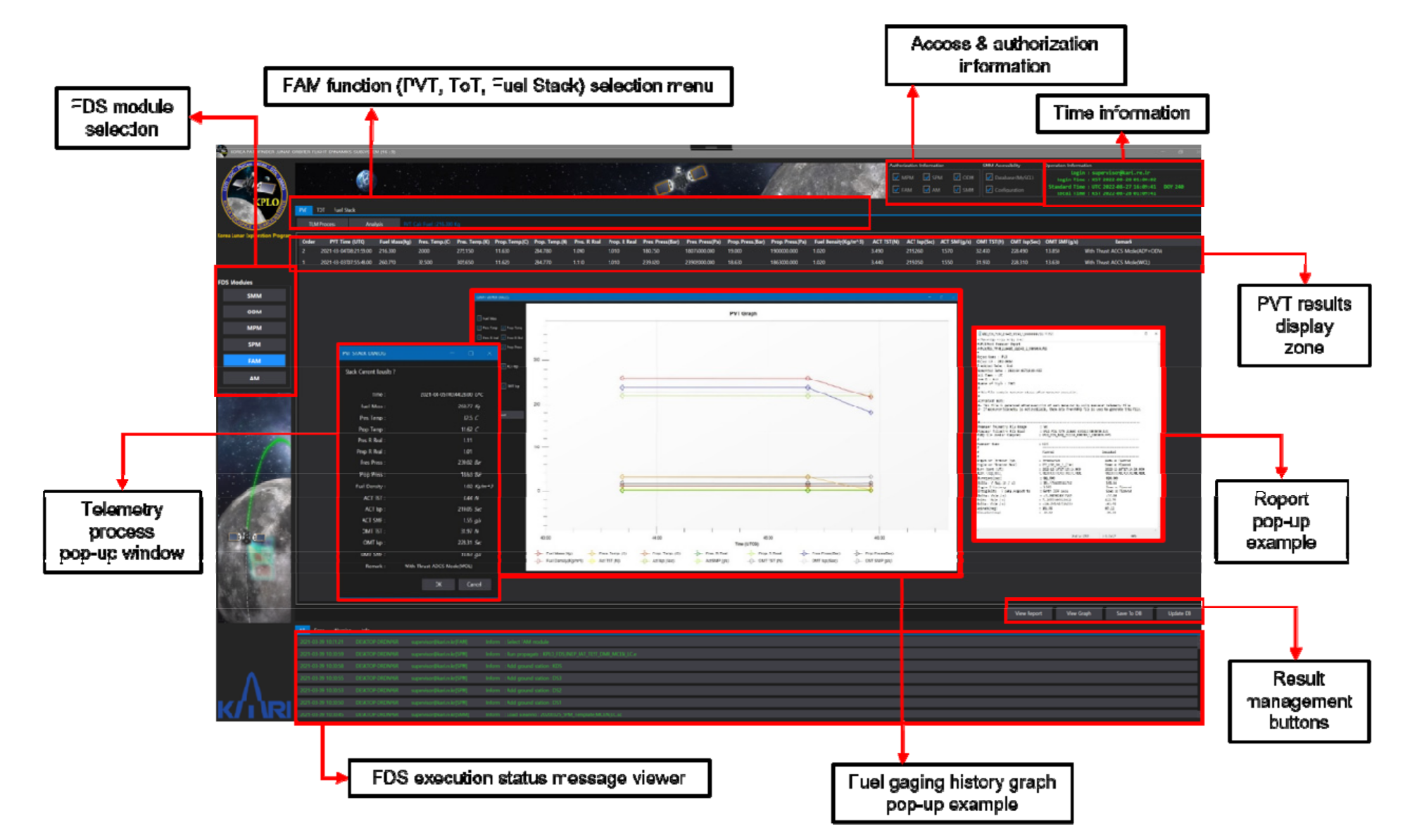
Figure 15 shows the GUI of the PVT tab among the functions of the FAM module. In addition, the GUI that pops up when the PVT function is performed or the generated output files, were captured separately and overlapped with
Figure 15.
4.2.6. Analysis Module (AM)
The main objective of AM is to perform miscellaneous analyses to support the FDS operator. To enable the operator to actively respond to various demands while operating FDS, the following tools or functions are implemented through AM.
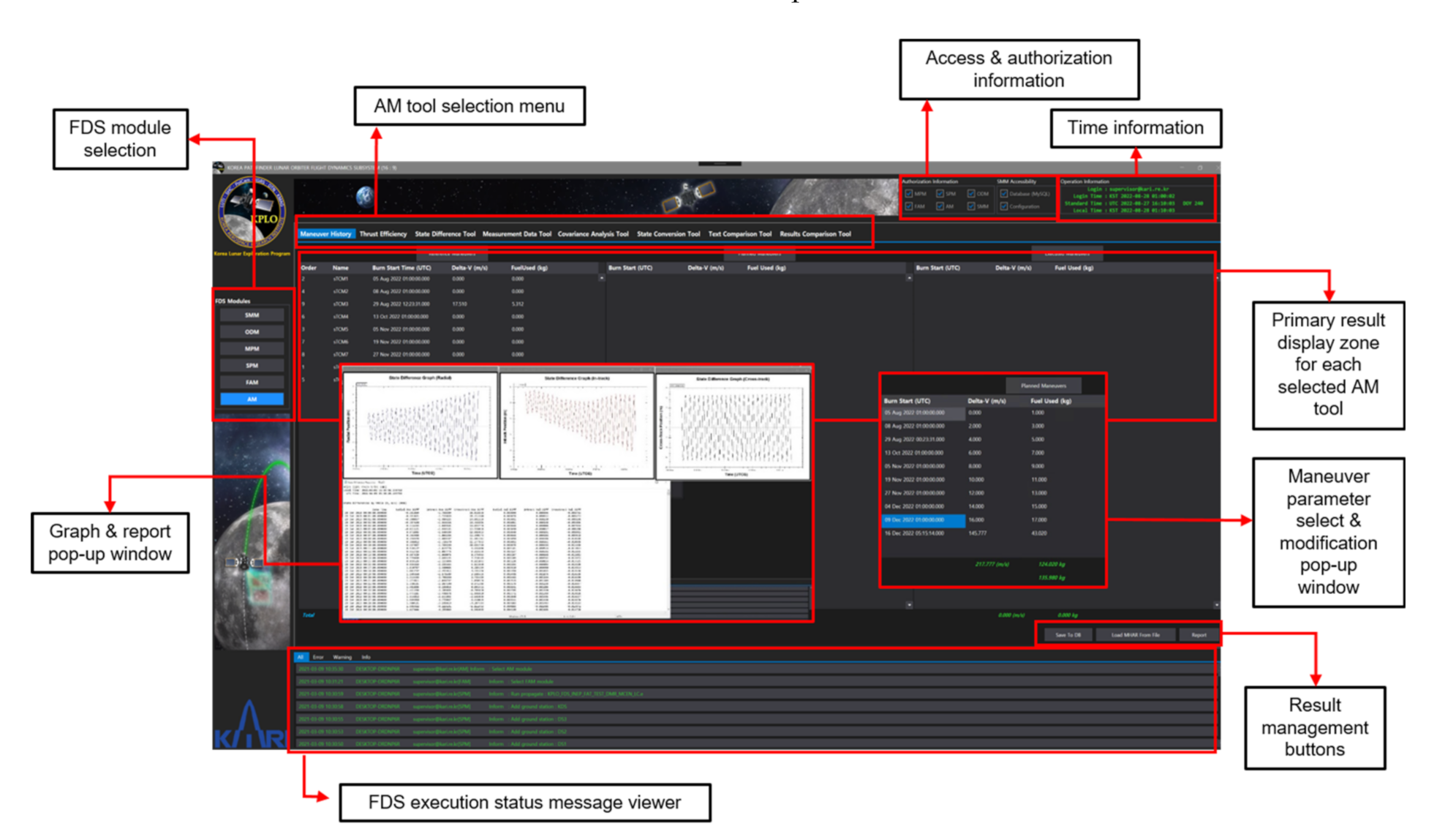
Figure 16 shows the GUI of maneuver history function, among the main functions of AM to be described below.
- -
Maneuver history
The maneuver history tool is designed to allow for a comparison of major maneuver parameters, such as the burn start time, the burn duration, the magnitude of , the mass of fuel used, etc., for each maneuver, between the reference and the executed maneuvers. The reference maneuver values are predicted values during the trajectory design, and the planned values are obtained during the actual maneuver planning operation in MPM using the definitive ephemeris from the ODM and the updated engine model from the FAM and AM. The executed values are achieved from the telemetry data. By using this function, the operator can continuously manage and monitor parameters related to the maneuvers during the actual flight in comparison to the values that are predicted at the trajectory design phases.
- -
Thrust efficiency
Through the thrust efficiency function, the FDS operator can estimate the thrust efficiency of each maneuver. Within the thrust efficiency function, it is possible to compare the thrust efficiency before and after each burn, and the FDS database inside of the SMM is updated based on the estimated thrust efficiency. The updated thrust efficiency is applied for the next maneuver planning inside of the MPM. The thrust efficiency function also includes a function to generate various text data files and graphs related to the predicted thrust efficiency.
- -
State difference tool
The state difference tool provides the operator to compare the various formats of ephemeris written in STK internal (.e) or orbit ephemeris (.oem) formats. The operator can select reference and target ephemeris files to be compared and can generate state difference reports associated with those files. Inside the state difference report, difference statistics are reported, including RMS and the Min. and Max. values of the position and velocity vectors compared in radial, in-track, and cross-track components. The operator can set up units to be reported, i.e., cm and cm/s, and can also utilize graphs for easy analysis.
- -
Measurement data tool
The measurement data tool uses prewritten template scenarios in ODTK to perform a given function. Through the loading of template scenarios, the measurement data tool supports the operator in performing various editing of the measurement data. As the KPLO mission will use measurement data in the TDM format as a basis, the raw measurement data in TDM format can be loaded, and the operator can select which files, as well as which contents, to be edited. Moreover, the measurement data tool provides a function that prints the graph of the measurement times vs. its type or vs. the tracker so that the operator can easily analyze the data.
- -
Covariance analysis tool
The covariance analysis tool has a function to support the covariance analysis of the KPLO trajectory or orbit data, as is predictable from the name. Similar to the measurement data tool, the covariance analysis tool uses its predefined template scenario with ephemeris files in STK internal (.e) that contains covariance information. With this tool, the operator can perform analysis on covariance statistics in radial, in-track, and cross-track components, as with 3D total values. Additionally, the covariance analysis tool provides a very powerful 3D visualization of the covariance ellipsoid to support the operator’s analysis.
- -
State conversion tool
Using the state conversion tool, it is possible to reprocess ephemeris generated in FDS. For example, the coordinate frame can be converted from/to with different central bodies with different reference axes, the time format can be transformed to suit the requestor’s preferences, and the state representation can be transformed, such as between Cartesian and orbital elements.
- -
Text comparison tool
The text comparison tool provides convenience for the FDS operator to make a direct comparison of two files. When the operator selects two products, the text comparison tool compares each product and changes the text color of the different parts in order to improve readability.
- -
Results comparison tool
The main function of the results comparison tool is to provide convenience so that the operator can grasp the differences between two different FDS-generated products at a glance. When the operator selects two different FDS-generated products, it not only plots each content of the product, but also has the function of calculating the difference between them and shows the results within plots, as well as text files.
