Technical Note

Overview of the Flight Dynamics Subsystem for Korea Pathfinder Lunar Orbiter Mission

1
Lunar Exploration Program Office, Korea Aerospace Research Institute, Daejeon 34133, Korea
2
School of Aerospace and Mechanical Engineering, Korea Aerospace University, Goyang 10540, Korea
*
Author to whom correspondence should be addressed.
Aerospace 2021, 8(8), 222; https://doi.org/10.3390/aerospace8080222
Submission received: 23 June 2021 / Revised: 30 July 2021 / Accepted: 2 August 2021 / Published: 10 August 2021
(This article belongs to the Section Astronautics & Space Science)

Abstract

:
Korea’s first lunar mission, the Korea Pathfinder Lunar Orbiter (KPLO), aims to launch in mid-2022 via the Space-X Falcon-9 launch vehicle. For the successful flight operation of KPLO, the Korea Aerospace Research Institute (KARI) has designed and developed the Flight Dynamics Subsystem (FDS). FDS is one of the subsystems in the KPLO Deep-Space Ground System (KDGS), which is responsible for the overall flight dynamics-related operation. FDS is currently successfully implemented and meets all of the requirements derived from the critical design phases. The current work addresses the design and implementation results for the KPLO FDS. Starting from overviews on KPLO payloads, bus systems, and mission trajectory characteristics, a review on KDGS is also treated briefly. Details on the design philosophy, unique characteristics, and functionalities of all six different modules nested inside the FDS with its Graphical User Interface (GUI) design are discussed. Moreover, efforts currently devoted to the flight operation preparation of the KPLO are summarized, including many collaborative works between KARI and the National Aeronautics and Space Administration (NASA) teams.

1. Introduction

The Korea Pathfinder Lunar Orbiter (KPLO) will be the first Korean satellite to fly beyond Earth’s orbit and is expected to be launched in the middle of 2022. The KPLO program started in 2016 and is led by the Korea Aerospace Research Institute (KARI). KARI launched its first multipurpose satellite, called Korea Multi-Purpose Satellite (KOMPSAT)-1, in 1999, and now operates more than 15 Earth-orbiting KOMPSAT series, including low Earth orbit (LEO) and geostationary orbit (GEO) satellites [1]. Starting from the KPLO, Korea’s space exploration activities are expected to be more accelerated, as Korea plans to focus on lunar surface investigations using landers and rovers by the end of 2030, and landing on asteroids is seriously considered by the end of 2035 [2]. Currently, Korea has just begun to consider another new deep space program, visiting the Apophis during its close approach to Earth in 2029.
The mission objectives of the KPLO have been set up as follows. The first is to secure critical technologies for lunar explorations, the second is to investigate the environment, which includes the establishment of a lunar topographic map to support future lunar landing sites selection, a lunar resources survey, and an investigation on the radiation environment, as well as the surface environment of the Moon. The final goal is to demonstrate and validate space internet technology. To accomplish the above objectives, the KPLO will carry six payloads to the Moon (the overview of each payload will be further explained in Section 2.1). The KPLO will be launched by the Space-X Falcon-9 launch vehicle in mid-2022. With the use of the Weak Stability Boundary (WSB)/Ballistic Lunar Transfer (BLT) method, the KPLO will be delivered to the final mission orbit around the Moon that has a 90 deg inclination with respect to the lunar equator. The nominal mission of the KPLO will be conducted at an altitude of approximately 100 ± 30 km throughout the one-year mission lifetime. To achieve this desired purpose, the KPLO bus system is currently in the stage of development completion, and a total assembly test is expected to be completed and finalized before the start of the launch campaign scheduled in March 2023. A more detailed overview of the bus system and trajectory design can be referred to in a separate Section 2.2 in this paper. Another very important segment of the KPLO mission is the ground segment. For the success of the KPLO mission, KARI has put much effort into developing, verifying, and validating the ground segment of the KPLO mission. The KPLO deep-space ground system (KDGS) is one of the components that completes the KPLO ground segment. With external ground networks (EGNs) and other entities, such as the Disruption tolerant network Control Center (DCC) and external user groups, KDGS completes the ground segment of KPLO to provide the relevant functionality for successful KPLO mission operation. More details on the KDGS architecture will also be discussed separately in Section 2.3.
Among the various functionalities of KDGS, such as telemetry reception and processing, command generation, transmission, ranging and tracking, mission planning, image processing, and scientific data processing, every flight dynamic-related activity will be conducted via the Flight Dynamics Subsystem (FDS). The FDS is one of the subsystems that configures the KDGS and will perform one of the critical activities throughout the KPLO mission operations. The FDS will perform orbit determination, maneuver planning, orbital event prediction, mission planning support, and orbit-related product provision for both image and science processing enhancement. The KPLO FDS has been inspired, designed, and developed under the past KARI FDS development and operational heritages with LEO and GEO missions. The KPLO FDS is designed to have six major functional modules: System Management Module (SMM), Orbit Determination Module (ODM), Maneuver Planning Module (MPM), State Prediction Module (SPM), Fuel Accounting Module (FAM), and the Analysis Module (AM), where each module has unique functionalities. Recently, the FDS was implemented successfully under the C# compiler environment and found to meet all of the requirements derived from the critical design phases. In this work, the design and implementation results for the KPLO FDS are treated, including detailed functionalities on every six different modules with its graphical user interface (GUI) design. The design philosophy of the KPLO FDS that is differentiated from the FDS of GEO or LEO satellites was also treated in detail, which is expected to support the further development of other FDSs for planetary exploration missions.
The remainder of this manuscript is organized as follows. A brief review of the KPLO systems, including the payload, bus system, and trajectory, as well as the KPLO KDGS architecture, is provided in Section 2. Various characteristics of the KPLO FDS, including the design philosophy, are described in Section 3. In Section 4, the configuration of the hardware and software, detailed functions of each module, and the implementation results of the FDS, including examples of GUIs, are described. Section 5 explains the preparation of the FDS operation, including the partnership between the KARI and National Aeronautics and Space Administration (NASA). The lessons learned are covered in Section 6 and, finally, conclusions are presented in Section 7. This paper contains details on how the FDS for the first lunar exploration mission to be performed in Korea is designed and developed and how to prepare related operations through cooperation with NASA. We believe that this paper will apply to the development and operation of FDS for space exploration in Korea in the future and will be able to inspire related communities to prepare for space exploration.

2. KPLO Overview

2.1. Payloads Overview

As already mentioned, the KPLO will have a total of six payloads, including a Lunar Terrain Imager (LUTI), a Polarimetric Camera (PolCam), a KPLO Gamma-Ray Spectrometer (KGRS), a KPLO Magnetometer (KMAG), a Disruption Tolerant Network Experiment Payload (DTNPL), and a Shadow Camera (ShadowCam), funded and supported by NASA. The LUTI will take images of the lunar surface with a high spatial resolution (less than 5 m) to investigate a candidate landing site to further prepare for Korea’s second-stage lunar explorations [3]. To investigate the characteristics of the lunar regolith, the PolCam will take polarimetric images of the entire lunar surface [4]. The KGRS will investigate the chemical composition of the lunar surface materials by mapping the spatial distribution of gamma-ray energy, which ranges from 10 keV to 10 MeV [5]. The magnetic strength of the lunar surface (up to ~100 km) will be measured via the KMAG with ultrasensitive sensors [6]. The ShadowCam will take the images of the permanently shadowed regions near the lunar polar regions to search for evidence of water ice deposits. The Lunar Reconnaissance Orbiter Camera (LROC) is the ancestor of the ShadowCam; however, the ShadowCam is approximately 800 times more sensitive than the LROC [7]. Finally, the DTNPL will conduct an interplanetary internet communication experiment on disruption tolerant networking [8].
Each payload is now fully developed, the final inspection is in full swing, and the associated operational concepts are being finalized by each payload’s hosting institution. The main science objectives for each payload, including the hosting institutions, are summarized in Table 1. Recently, NASA has selected nine US scientists to join the KPLO mission through the KPLO Participating Scientist Program (PSP) to maximize the scientific return from the KPLO mission. The PSP is run by both NASA’s Science Mission Directorate (SMD) Planetary Science Division (PSD) and the Human Exploration and Operations Directorate (HEOMD) Advanced Exploration Systems Division (AES) [9].

2.2. Bus System and Mission Trajectory Overview

The overall launch mass of the KPLO is expected to be approximately 678 kg, including the above six payloads. The original transfer method to reach the Moon was to use a 3.5 phasing loop orbit around the Earth; however, the WSB/BLT method was recently selected to save delta-V, Δ V , which ultimately secure more fuel for KPLO. Actually, it is well known that an average of about 160 m/s of Δ V savings can be achieved by selecting the WSB/BLT method compared to the conventional transfer method to the Moon [10], and the KPLO indeed saved about 165 m/s of Δ V .
With the WSB/BLT method, the current baseline launch period for the KPLO is approximately 40 days (from late July to early September 2022). After several months of transfer, the KPLO will arrive at the Moon in mid-December 2022 and will begin the Lunar Orbit Acquisition (LOA) phase to be inserted into the Moon. During the LOA phase, which is expected to take approximately 15 days, the KPLO will conduct a total of five Lunar Orbit Insertion (LOI) burns to achieve its final mission orbit. Immediately after the LOA phase, the commissioning phase will be initiated for an approximately one-month period. During the commissioning phase, not only the KPLO bus system, but also all of the onboard instruments will be calibrated and validated to conduct the upcoming one-year nominal mission around the Moon. To successfully deliver KPLO to the Moon, KPLO is designed to have a four Orbit Maneuver Thruster (OMT), with approximately 31.8 N of thrust with 227 s of the specific impulse, Isp, for large burn execution, and eight Attitude Control Thruster (ACT) with approximately 3.48 N with 218 s of Isp for small burn execution. All of these engines will be clustered for burn executions. Four OMT engines will be clustered to be used for the main thruster set for large burns during the transfer and LOA phase, i.e., LOIs as well as large-sized Trajectory Correction Maneuvers (TCMs) that require more than 10 m/s of Δ Vs . For small burns, such as for TCMs less than 10 m/s, momentum dumping, and orbit maintenance during the nominal mission phase, eight individual ACT engines will be clustered into sets of two ACT and will be used. These two ACT sets will also be used for liquid setting purposes as well as attitude maintenance before and during large burns.
The stowed and in-flight configuration of the KPLO spacecraft is shown in Figure 1, and the WSB/BLT transfer trajectory during the launch period and the orbit of the LOA phase are shown in Figure 2. On the left side of Figure 2, the WSB/BLT transfer trajectory with respect to the Earth–Sun rotating frame is depicted, and the LOA phase in the Moon Inertial frame is shown on the right side of Figure 2. After completion of the 1-year nominal mission, the KPLO can enter the extended mission phase within the possible range of the amount of fuel remaining. Recent progress on various KPLO trajectory designs and analyses has been reported in Refs. [11,12,13,14,15,16,17,18,19,20,21,22,23,24,25,26,27,28,29,30,31,32]. The reader may refer to the WSB/BLT transfer trajectory as well as mission orbit design results for the KPLO spacecraft in Refs. [11,12,13,14,15]. The orbit determination simulation results with respect to different mission phases of the KPLO are discussed [16,17,18,19,20,21,22,23] along with trajectory and orbit analysis results under the consideration of various flight error sources [24,25,26,27]. The operational concept establishment and related analysis are covered in Refs. [28,29,30,31,32].

2.3. KPLO Deep-Space Ground System Overview

As already mentioned, KDGS will play a very important role in the success of the overall KPLO mission. The KDGS will be implemented at the KARI site with subsystems, including the Korea Deep-Space Antenna (KDSA). The top-level architecture of KDGS is shown in Figure 3.
As shown in Figure 3, the KDGS completes the KPLO ground segment with other entities, such as DCC and the external Science Operation Center (SOC), through EGNS. The functionalities of major KDGS subsystems are as follows. KDSA is a 35 m aperture deep-space antenna with a high-power transmitter that is capable of tracking and communicating with KPLO during the mission. Figure 4 shows the state of KSDA, which is currently under construction. A real-time operation subsystem (ROS) will generate, send, and receive telecommands (TCs) and telemetry (TM), and will monitor the spacecraft health status in real time. The Mission Planning Subsystem (MPS) will generate mission timelines and commands for both the bus system and payloads. The MPS will also manage payload data gathering schedules to maximize data gatherings within a limited mission lifetime, while maintaining resource allocation constraints. LUTI data will be processed by the Image Calibration and Analysis Subsystem (ICAS) in KDGS, and the Science Data Management Subsystem (SDMS) will handle other science payload data and preprocess them to deliver payloads and developers for further scientific research. The science data products will comply with the PDS4 standard established by NASA.
As the KPLO program will utilize the NASA Deep Space Network (DSN), KDGS will have an interface with the NASA DSN. The Goldstone Deep-Space Communication Complex (DSCC), the Madrid DSCC, and the Canberra DSCC will be primary service facilities during the transfer phase. Goldstone and Madrid will still be the primary service facilities, while the Canberra DSCC will serve as the backup for KDSA anomalies during the nominal mission phases. KDGS will also have functions to support the Space Link Extension (SLE) protocol and the DTN node. Finally, the FDS is one of the critical subsystems that is responsible for overall flight dynamics-related operations, which will be introduced in detail through this work.

3. Design Philosophy of the FDS

3.1. Utilization of COTS

Despite many real flight dynamics backgrounds on LEO and GEO missions, the decision was made to adopt Commercial-Off-The-Shelf (COTS) software to formulate FDS for the KPLO mission. This decision was made to secure the operational stability related to flight dynamics, considering the characteristics of the KPLO being Korea’s first lunar mission. Among the several COTS software programs, the Orbit Determination Tool Kit (ODTK) and System Tool Kit (STK) with Astrogator (an add-in module of the STK) by Analytical Graphics Inc. (AGI) is selected. The criteria for selecting a COTS were whether there were cases applied to actual flight missions in the past and whether the FDS function could be freely implemented using COTS, that is, its expandability was considered the most. The Astrogator is the third and most recent version of a program originally developed by NASA Goddard Space Flight Center (GSFC) and has been used to design and operate many missions; not just Earth missions, but also missions with a central body other than the Earth, such as Clementine, Wind, SOHO, ACE, Lunar Prospector, MAP, LRO, and LADEE [33].
At the same time, in-house software, especially the core algorithm related to the flight dynamics of the planetary mission, is now being developed based on KARI’s heritage of past LEO and GEO missions [34,35,36,37,38,39,40,41,42] to prepare for future space exploration in Korea. During the operation of the COTS-based FDS, the performance of the developed in-house software will also be validated using the real navigation and flight data of the KPLO. After the KPLO mission, the authors strongly expect that the developed in-house software will replace the COTS software and be further used for space exploration missions in Korea after the KPLO mission.

3.2. Interface with the Trajectory Design System

While establishing the early FDS design concept, the decision was made not to include the trajectory design function into FDS, and instead prepare another subsystem called the Trajectory Design System (TDS) while maintaining interoperability with FDS. This was intended by regarding the characteristics of interplanetary trajectory design work, which can only be designed by a subject matter expert and that the design itself cannot be automated. Additionally, complex targeting sequences could be broken down many different ways depending on the results of previous execution results. Therefore, the final decision was made to operate standalone TDS by directly using STK/Astrogator.
One of the important features of the TDS is that the operational “template scenario” will be generated inside of the TDS and delivered to the FDS. This design strategy is the result of differentiation from the FDS design and operation of typical LEO and GEO satellite missions, which do not have a high dependence on trajectory or orbit design results during flight operation. More detailed reasons for this special feature will be explained in Section 3.3. During the flight operation of the KPLO, the TDS will maintain close contact with the FDS and will share many products. During KPLO’s operation, TDS will continuously observe whether KPLO follows the designed reference trajectory, i.e., whether the current trajectory information satisfies the predefined error boundary and will update reminders of the reference trajectory. In the process of checking whether KPLO follows the reference trajectory well, the TDS will receive and utilize many products generated by the FDS, including the navigation data, the current fuel mass estimates, the engine’s thrust, and Isp estimates with its efficiencies. During KPLO’s mission operation, the TDS operator will closely monitor the current status of KPLO, together with the FDS operator. In Figure 5, the top-level interoperability architecture between FDS and TDS is shown.

3.3. Template Scenario

The key feature of the KPLO FDS is that most of the FDS functional modules will be run by loading the reference “template scenario”. The FDS module executed by loading the template scenario is as follows: ODM, MPM, SPM, and some features of AM. Any existing previously saved sets of STK and ODTK scenario files can be directly used as template scenarios inside of the FDS. When establishing the concept of a “template scenario” loading-based operation, one of the top priorities considered was to automatically detect the activated parameters inside of the template scenario and to only display those parameters in the GUI of the FDS. This strategy will maintain user controllability while minimizing GUI changes, and even replacing the template scenarios. This effort resulted in the maximization of FDS applicability to any situation that may occur during the real-time operation, which could likely happen, namely, replacing the template scenario that has different parameters to achieve each module’s final objectives.
Similar to the KPLO FDS, the FDS for the LADEE mission also utilized COTS software (STK, Astrogator, and ODTK) and used a similar approach called operational “Procedures”. The procedure, in terms of LADEE FDS, is a list of script-based tasks written with the VB.NET language. Inside the procedures, there exists a subfunction called the “load scenario”, which is very similar to those of the KPLO FDS [43]. However, to modify the task of LADEE FDS, the operator needs to know more specifics of the COTS tool’s Application Programming Interface (API) than the current design of KPLO FDS, since KPLO FDS loads the entire template scenario using just one click and automatically displays user-activated parameters. By applying KPLO FDS’s own unique strategy, wide ranges of trajectory options can flexibly consider achieving the final mission goal during real flight operations. Rapidly dealing with contingency situations during actual operation, i.e., unavoidable reference trajectory changes due to burn failure, could be one of the most promising applications as flight dynamics operators can reconstruct a reference trajectory to target a new aim point using any supporting parameters nested.
As an example of an MPM loading operational template scenario that will be constructed from the inside of the TDS, there will be two different sets of template scenarios called the Operational Trajectory Template Scenario (OTTS) and the Contingency Trajectory Template Scenario (CTTS). As their names indicate, the OTTS is constructed for the nominal operation phases of the entire mission, and the CTTS is intended to use when a contingency trajectory situation occurs. When producing OTTS, the most prioritized facts were to follow the designed reference trajectory well and, at the same time, satisfy the Δ V limits given in each of mission phases. The most ideal way is to use the scenario created to generate the reference trajectory in TDS directly as OTTS. Unfortunately, this is impossible, as most of the reference trajectories, especially KPLO, which uses the WSB/BLT trajectory, calculate the reference trajectory with various targeting parameters using forward-backward shooting at the same time. The template scenario in which the forward-backward shooting method is used is not suitable as an OTTS, and it needs to be converted to the template scenario utilizing only the forward sense. While converting into OTTS, various conditions need to be considered. Some important points are listed as follows. First, statistical TCM locations are properly located and nested inside an OTTS by regarding the expected navigation, trajectory, orbit prediction, and spacecraft burn performances. These locations of statistical TCMs are of no major interest when generating the reference trajectory itself inside of the TDS, except the location of the deterministic TCMs. Second, the OTTS should be constructed considering real-flight operation timelines, such as regarding the time zone of the operation center and the operator’s shift work schedule. Finally, and most importantly, the targeting parameter and associated convergence tolerances are set to be different while following the reference trajectory well rather than those of the original set of scenarios that are used for reference trajectory generation. These measures were used to consider the convergence performances as well as their speed, assuming the actual operation situation.

4. FDS Implementation Results

4.1. Hardware and Software Configuration

KPLO FDS will have a primary and redundant set structure with a server–client component for each set. Four workstations will be used for FDS clients (two for the primary client and two for the redundant client) and two servers (one for the primary server and one for the redundant server) for the FDS data server. The C# programming language will be used on Microsoft. NET framework is used for FDS implementation for COTS simulation engine integration. Each of the FDS servers has an Intel Xeon W-2145 3.7 GHZ 8 core CPU, 64 GB of RAM, and an NVIDIA Quadro RTX 4000 8 GB GPU. The performance specifications of the client workstation are an Intel Core i5 CPU with 32 GB of RAM with an Intel UHD graphic 630 GPU and a 3840 × 2160 4 K resolution. The performance of the server was selected as a specification that the COTS software could operate without problems, and the client workstation was less than the server, but the display resolution aspect was considered to be slightly more. The FDS software and COTS software will be installed in the server and will mainly store every FDS-related dataset, including reference template scenarios for each module. The operator will mainly work on the client workstations, where each client workstation is connected to the server to provide a remote desktop connection function. Data between the primary and redundant servers will be backed up regularly by user-defined cycles. The FDS provides a setting function that allows the user to set the backup cycle. If the primary server system does not work normally, then an operator can just switch to a used redundant server, as well as clients, for the remainder of the FDS operation. In Table 2, the software version used in FDS is summarized.

4.2. Functional Allocation

As already mentioned, KPLO FDS consists of six major functional modules: SMM, ODM, MPM, SPM, FAM, and AM. Each module performs a unique function that is indispensable in supporting the execution of the entire KPLO mission. The unique functions of each module were designed considering the operational characteristics of each mission phase of the KPLO mission. 
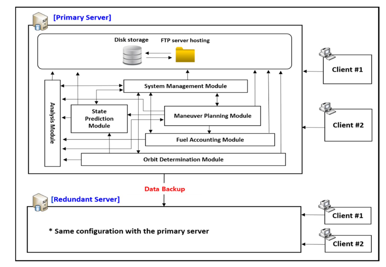
Figure 6 shows the architecture of the functional modules associated with the primary–redundant structure of the KPLO FDS. A summary of the key features for the six modules is shown in Table 3. In the following subsections, detailed functionalities for each of the six major modules will be described.

4.2.1. System Management Module (SMM)

The SMM module has the main function of systematically managing and setting up the entire FDS system environment. The operator can set up and configure KPLO FDS through SMM. SMM provides a total of five main functions, as follows.
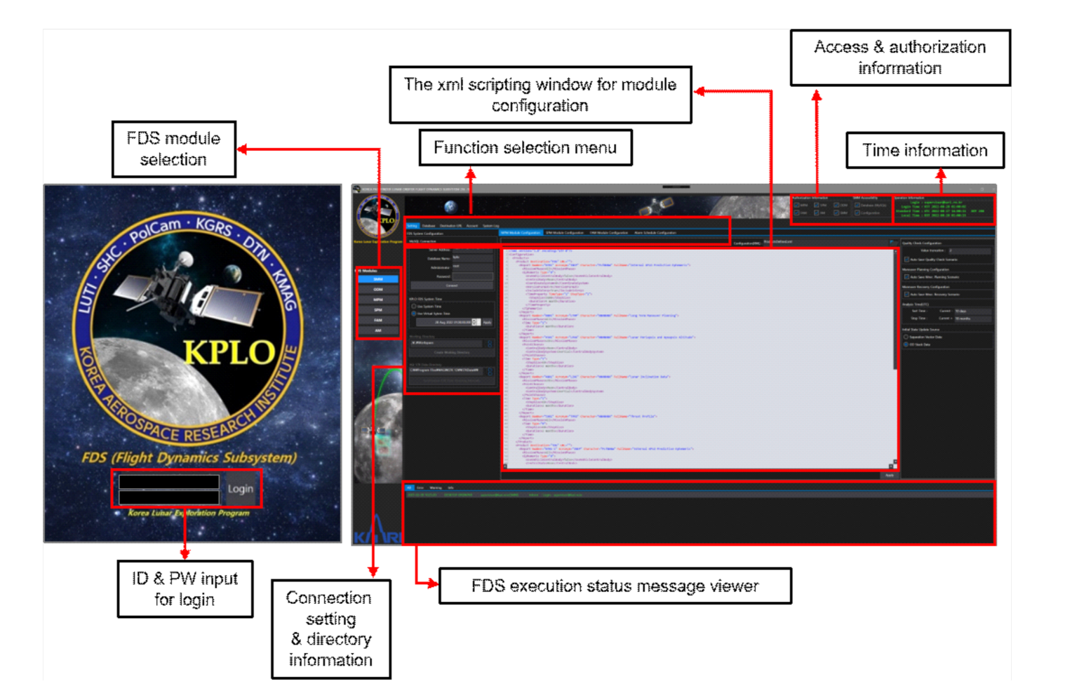
First, the operator can perform the setting for each module of the FDS by using the xml script or via the setting dialog on the screen. As an example of the SPM module configuration through SMM, the generation period, period, and interval of outputs to be generated in the SPM can be defined and registered in advance through an xml script, and related contents can be changed simply by modifying the xml later. Second, under the name of the FDS database, the management of various parameters is performed as follows through SMM. Various parameters include those related to the KPLO bus system, force modeling parameters used for each mission phase, thruster and engine configuration, and tracking station information, etc. Some parameters managed by the FDS database will be updated periodically based on the calculation results of the submodules during FDS operation. Actually, all parameters in the FDS database can essentially be updated during operation, but updates during the operation are limited to being performed only by authorized users. Third, SMM has the function of registering and managing the information of the target destination for the delivery of various products generated in FDS through FTP. Fourth, FDS user information can be registered (ID and PW) and managed through SMM. While registering a user account, each user’s accessibility to the FDS functional module can be limited and granted, depending on each operator’s role and responsibility. Finally, system log management is possible in SMM. The FDS log history can be tracked and searched for certain kinds of tasks, for example, which parameters were changed by each user or period of use, in the FDS. The left side of Figure 7 shows the first login screen of the KPLO FDS, and the right side shows the main screen of the SMM module.

4.2.2. Orbit Determination Module (ODM)

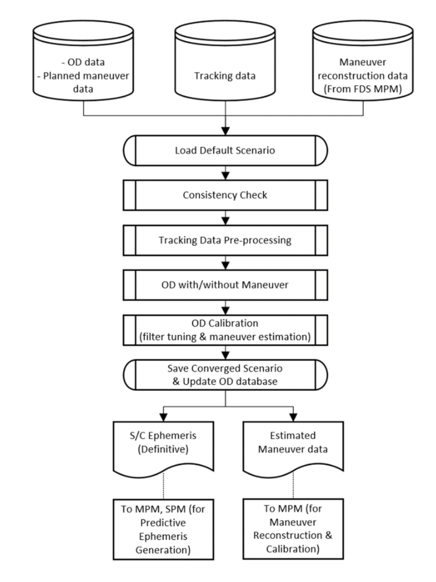
Orbit determination (OD) is a key part of the flight dynamic operation of KPLO. For stable and reliable mission operation, OD and orbit prediction (OP) should be suitably performed by the ODM of the FDS. The ODM has several functions for space navigation, such as initial orbit determination (IOD) for the initial acquisition after separation from the launch vehicle’s upper stage, operational orbit determination (OOD) for translunar and lunar orbit phases, and a maneuver estimation for maneuver reconstruction and calibration. The data generated by ODM are exchanged to the SPM and MPM. FDS ODM employs a scenario-based flow for effective KPLO mission operations, as shown in Figure 8.
The ODM uses previous orbit stack data, planned maneuver data, tracking data, and maneuver reconstruction data from the FDS database. The first step of the ODM implementation procedure is a loading default template scenario. The prepared scenarios, such as IOD and OOD, can be loaded into a default working directory of FDS ODM. The IOD scenario determines the initial orbit after separation from the launch vehicle’s upper state using ground-based measurements. The OOD scenarios have four different types for different phases: Trans-lunar cruise (TLC), LOA, LOI, and lunar mission. The operator has to select the proper default scenario after checking the mission phase.
After scenario loading, a consistency check is run to compare the parameters used, such as the propagator, spacecraft, and tracking station, to those of the FDS database. A consistency check is a very powerful tool. By automatically confirming the correspondence between the numerous parameters used in the updated template scenario and the parameters currently used in the FDS database, errors due to unexpected parameter settings can be prevented. It is a very useful approach for OD to start using the same parameters of trajectory design and analysis. These parameters can be adjusted during orbit trending, or during the calibration process after the first trial. Then, tracking data preprocessing is accomplished for initializing and editing the tracking files. The KPLO mission mainly employs range and Doppler tracking data from KDSA and NASA DSN for OD. The CCSDS Tracking Data Message (TDM) format is the default for tracking measurements [44] of FDS ODM. In this procedure, the format of tracking is quickly checked, and abnormal or bad tracking points are edited by the operator. For tracking data preprocessing, the measurement edit tool of FDS AM can also be used before OD processing.
The next step is the OD with or without the maneuver process. In this stage, orbit estimation is performed using a priori state values and preprocessed tracking data. As already discussed, FDS ODM uses AGI ODTK, which employs a sequential estimation technique based on an extended Kalman filter and fixed-point backward smoother. The state estimation process is then iterated until the results satisfy the convergence criteria. A priori state values can be acquired from orbit stack data or a previously determined ephemeris. If maneuvers such as TCM, LOI maneuvers, and the Orbit Maintenance Maneuver (OMM) are included in the OD target period, then maneuver estimation is also performed. Planned maneuver information is then utilized for the initial values of maneuver components. An orbit quality check is also performed in OD with or without a maneuver process step. A post-fit residuals analysis, an error covariance analysis, an orbit overlaps comparison, and an external orbit comparison are considered for the orbit accuracy investigation.
Next, OD calibration via filter tuning for better parameter estimation and maneuver estimation is prepared. Bias calibration and maneuver estimation calibration can be included in the OD calibration. Finally, products of the ODM, such as spacecraft internal definitive ephemeris, OD reports including estimated maneuver data, consistency check reports, OD reports, and orbit stack files, are saved and delivered to other subsystems. Spacecraft definitive ephemeris is delivered to MPM and SPM, and the estimated maneuver data are stored for maneuver recovery and reconstruction.
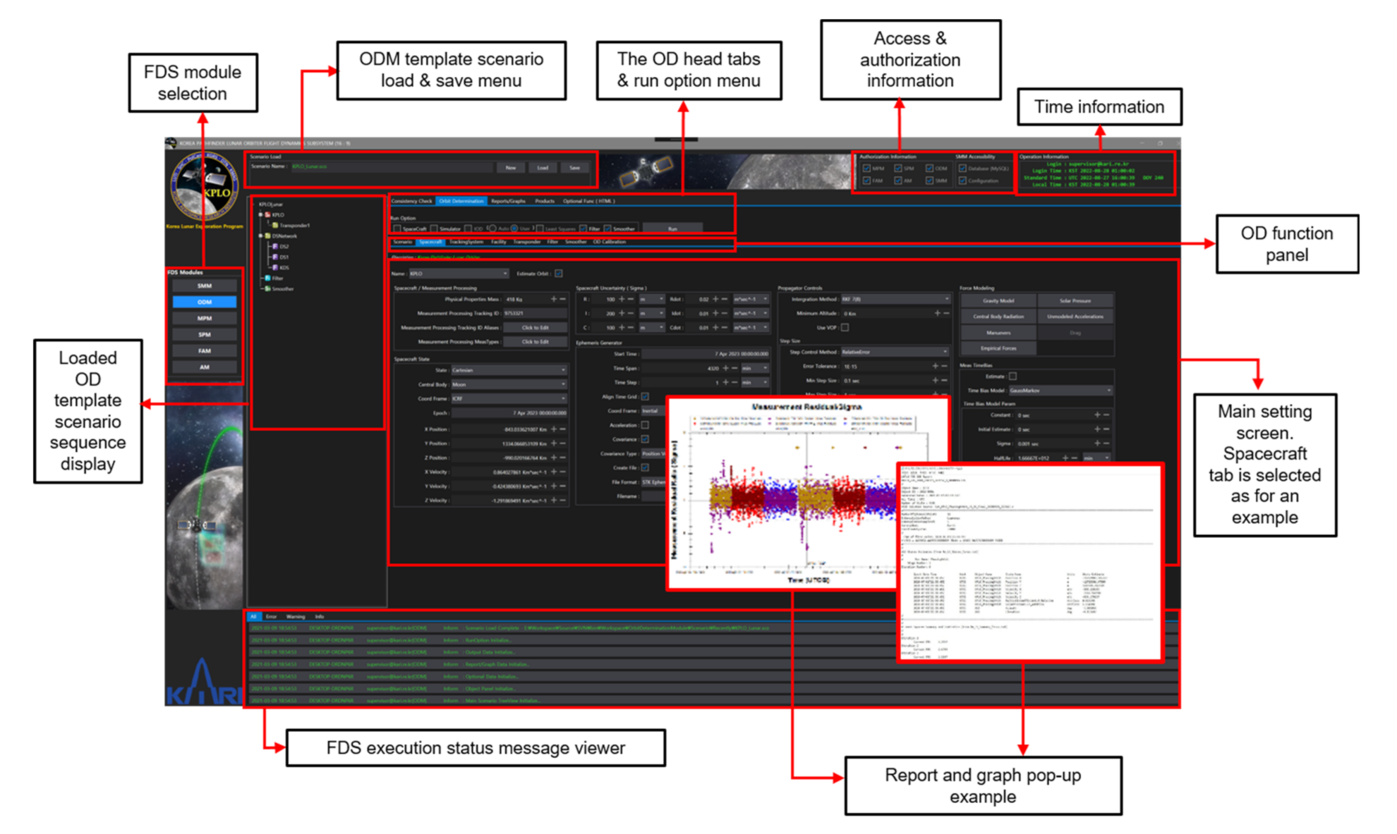
The main screen of the ODM is shown in Figure 9 as an example with the spacecraft tab selected. The operator can set various spacecraft-related parameters, as well as astrodynamic modeling parameters inside of this spacecraft Table. The pop-up screenshot of the output generated by the ODM is also captured and shown in Figure 9.
The head tabs are prepared considering the operational OD procedure (a consistency check with the FDS database, run OD, generate reports and graphs, product generation, and some optional functions). The scenario panel, log windows, function panels, and run option checkboxes are included in the main screen of FDS ODM. The function panels consist of various tabs for the execution of OD procedures, such as scenario information, spacecraft setting, tracking system configuration, filtering and smoothing, and OD calibration. The scenario tab displays the information of the loaded scenarios, such as global dynamic modeling parameters, central body, planetary ephemeris, and tracking measurements. The spacecraft tab shows the states, covariance, force modeling, and numerical integration method. The filter and smoother tabs describe the control parameters of sequential estimation. Data editing and maneuver estimation settings are included in this Table. The OD calibration tab is prepared in order to improve the OD results by modifying the force modeling, the initial orbit uncertainty, and the tracker calibration information. Other modeling parameters, such as solar pressure, central body radiation, un-modeled acceleration, air drag, and maneuvers, are also adjusted in the OD calibration Table. The internal spacecraft ephemeris, OD report, consistency check report, and orbit stack files are generated and sent in the products tab.

4.2.3. Maneuver Planning Module (MPM)

The purpose of the MPM is maneuver planning using a detailed thruster configuration to target the desired mission trajectory. The main functions of the MPM are to construct a trajectory utilizing the definitive ephemeris from the ODM, construct a trajectory with a finite burn considering the thruster set, perform a quality check of the maneuver planning result, generate the associated reports and graphs, perform maneuver recovery regarding the executed maneuver, and generate the updated predicted ephemeris for the SPM. The goal of the maneuver planning process is to design, verify, and validate the maneuvers for the maneuver request and the predicted ephemeris generation. In the MPM, it is necessary to perform a consistency check, maneuver planning with a thruster set, a quality check, and product generation sequentially.
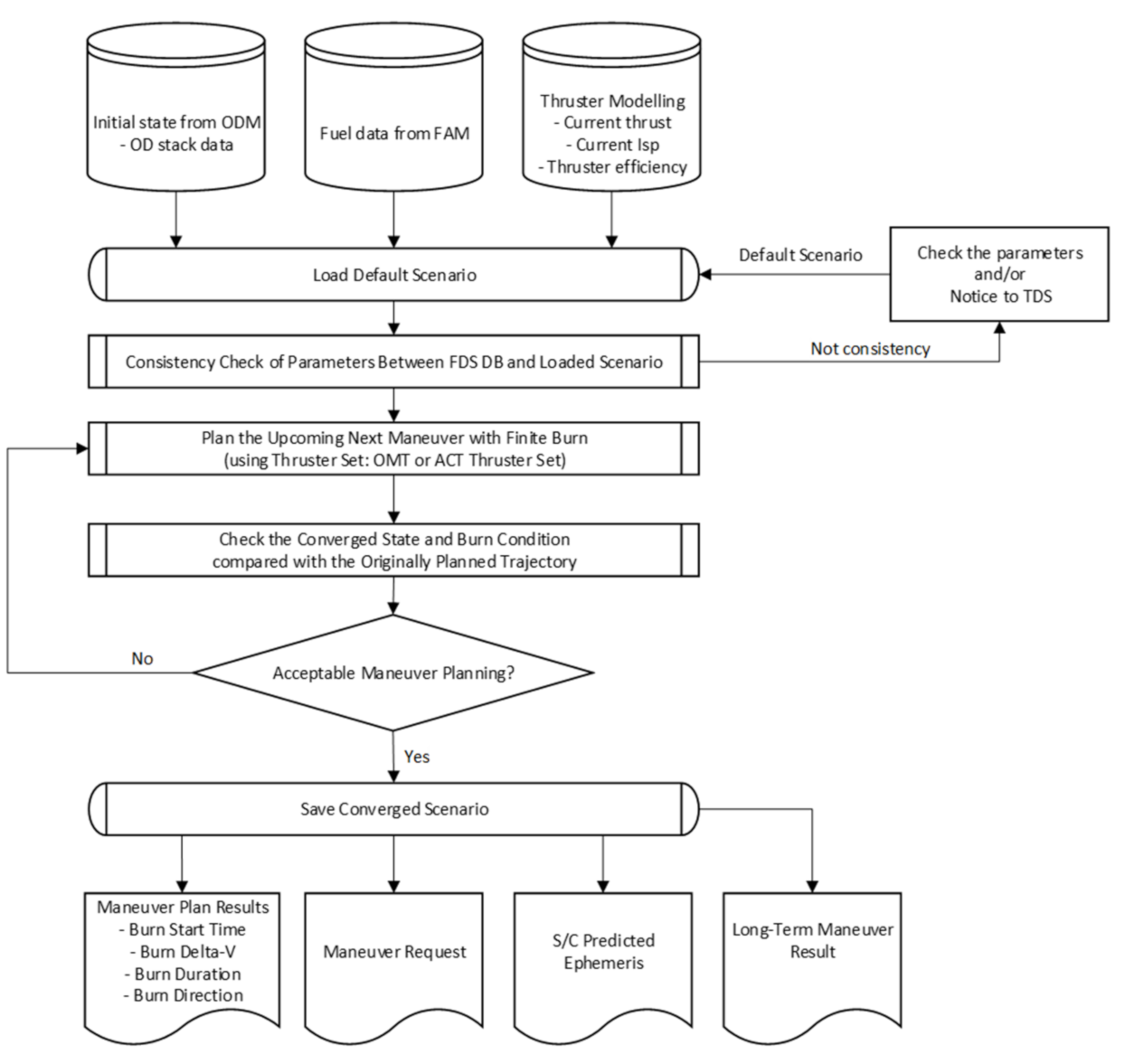
Figure 10 shows the overall workflow of the maneuver planning. First, the updated scenario is delivered from the TDS to the FDS, and is loaded in the MPM with parameters including the propagation, S/C fuel, thrusters, etc. Next, the MPM performs a consistency check to compare those parameters between the loaded scenario and the FDS DB. If the parameters of the loaded scenario are not consistent with those of the FDS DB, the MPM generates and sends the consistency check report to the TDS. After that, the operator can change the updated parameters in the loaded scenario. If those parameters are entirely consistent, then the MPM plans the upcoming next maneuver with the definitive ephemeris from the ODM and the corresponding thruster set with an updated engine model from the FAM. In the MPM, two types of thruster sets are considered with the cant angle: ACT and OMT. This is the baseline for selecting the thruster set according to the maneuver Δ V ; the thruster set of ACT will be used for the maneuver with a Δ V below 10 m/s, and the thruster set of OMT is used for the maneuver with a Δ V above 10 m/s. Note that the ACT will be used to maintain attitude control during the OMT burns and to desaturate the reaction wheels. In addition, the ACT will be used as a liquid settling burn before the OMT burn, which can reduce the slosh dynamics during the OMT burn. Therefore, the operator can plan the upcoming next burn by selecting the thruster set according to the maneuver; for example, the LOI maneuver needs more than 600 m/s, and therefore the LOI maneuver will be planned using the thruster set of OMT with a liquid settling burn. The thrust and Isp values of each thruster set are updated in the FAM after the maneuver execution, and those updated values are implemented in the maneuver planning process.
After maneuver planning, the MPM performs a quality check process of the planned upcoming next maneuver. In this process, practical values considering the KPLO bus system are applied to the planned maneuver, such as the burn start time, burn duration, and burn direction. In the current version, the operator can truncate the burn start time in 1 s increments and the burn duration in 0.25 s increments. Moreover, the burn direction is truncated to 2 decimal places, which is described in the azimuth and elevation angles in the Earth International Celestial Reference Frame (ICRF). After modifying those values, we can check and validate the Δ V of the remaining maneuvers regarding the total Δ V and fuel budget. Finally, the MPM generates the corresponding reports and graphs, including the maneuver request report, the predicted ephemeris, the long-term maneuver planning report, the maneuver setting report, etc. The MPM sends those reports to other modules of the FDS, other KDGS subsystems, and the External Data Server (EDS).
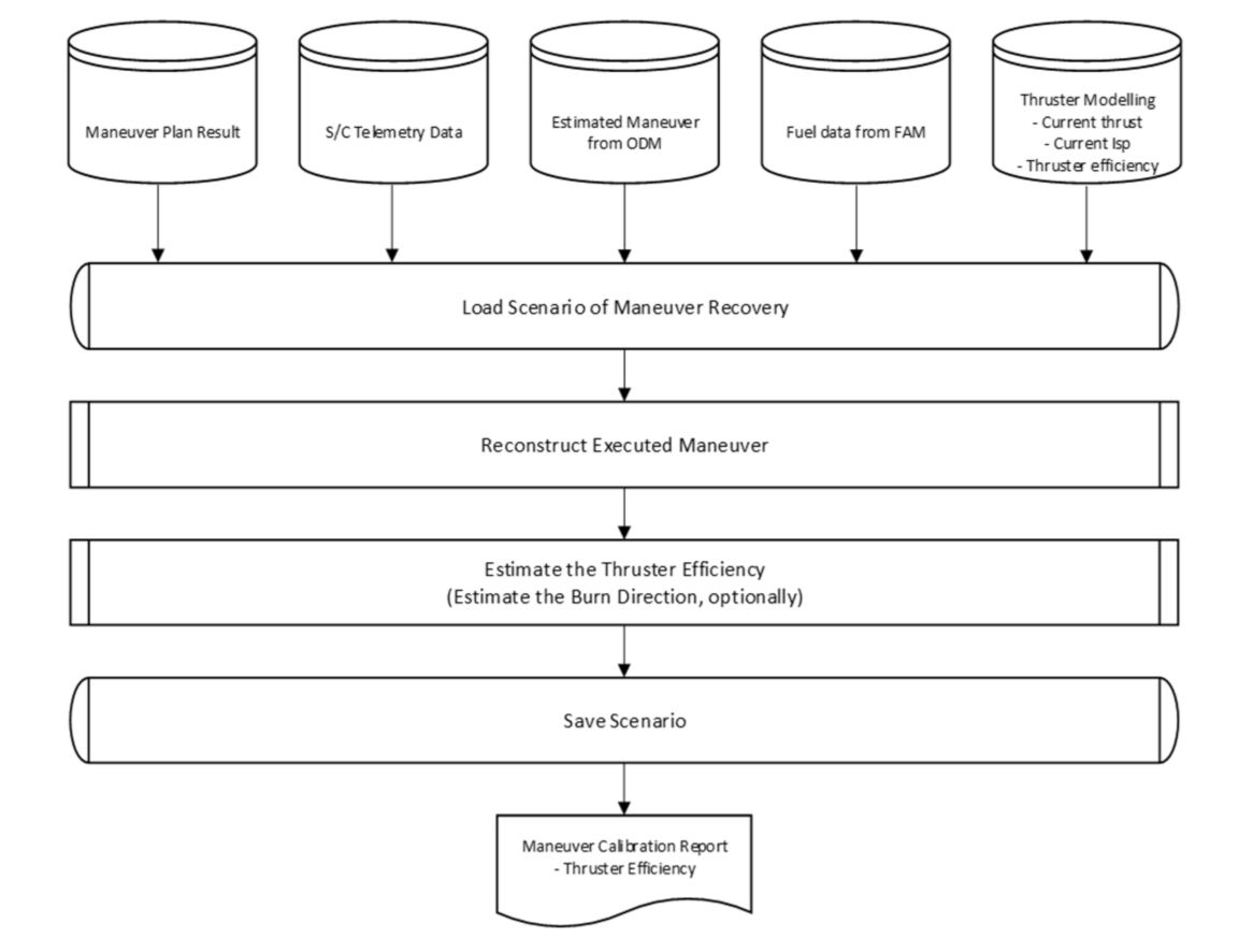
After maneuver execution, the MPM performs the maneuver recovery process. In this process, the executed maneuver is estimated using the telemetry data from the spacecraft. Figure 11 shows the overall workflow of the maneuver recovery. First, the maneuver recovery scenario is loaded with the maneuver planning report and the maneuver execution telemetry data from the KPLO. Moreover, the definitive ephemeris, including the executed maneuver from the ODM, is loaded. Using those data, the MPM mainly calculates the thrust efficiency and can optionally estimate the burn direction of the executed maneuver. For maneuver recovery, the control parameter and the propagation duration have an effect on the performance of the thrust efficiency estimation. In the KPLO FDS MPM, three types of control parameters are considered: The orbit element difference, the radial, in-track, and cross-track (RIC) component difference, and the position difference. In addition, the MPM prepares to select a propagation duration after the maneuver execution according to the maneuver. For example, the propagation duration can be selected as 3 h and 1 day after maneuver execution, with propagation to the lunar apoapsis. As a result, the MPM generates the corresponding reports and graphs, including the maneuver calibration report. These results are used in the thrust efficiency function of the AM.
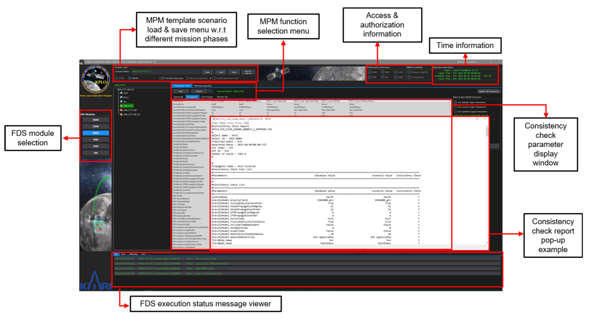
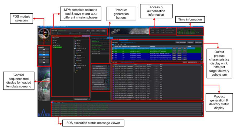
Figure 12 shows the example GUI of the consistency check function and the corresponding report of MPM. When the operator selects the consistency check tab, the parameters between the loaded scenario and the FDS DB are checked before maneuver planning. After completion of the consistency check, the operator can then perform the maneuver planning function. The operator loads the OD stack data as an initial state and selects the proper engine model according to the burn magnitude to perform the maneuver planning. Then, the target sequence is performed in order to match the target values with the finite burn. As a result, the convergence state is shown in the FDS MPM. The predefined products of the maneuver planning are generated, as shown in Figure 13. The operator can then generate the corresponding reports by selecting the button as shown in the middle of the screen and find them on the right side of the screen. In addition, the operator can generate graphs, such as the lunar inclination and the altitudes of the lunar apoapsis and periapsis, during the mission phase. Those generated reports can be sent to the KDGS subsystems and EDS.

4.2.4. State Prediction Module (SPM)

The main job of the SPM is to predict the states of the KPLO as well as a mission-related trajectory or orbital events and create the related data files. Most FDS products are produced in SPM and delivered to various subsystems. The delivered products are used to operate the KDSA and DSN antennas, establish and operate the operation plan of the bus system, establish and operate the operation plan of the payload, and support postprocessing of the payload scientific data. Generated products will differ concerning different mission phases, such as the Earth-centered phase and the Moon-centered phase, which consists of a late cruise and the start of the commissioning phase. The SPM has the ability to inspect generated products via text editors and graphs and has a function to deliver products requested by other subsystems via FTP. Typical examples of files created by SPM and transferred to other subsystems include predicted and definitive ephemeris, ascending and descending node predicts, mission eclipse predicts, planetary ephemeris including the Sun, Earth, and Moon, ground station view predicts, solar conjunction predicts, station acquisition information, etc. SPM uses predefined template scenarios to generate the major outputs for each mission phase. In addition, in this template scenario, identification IDs are assigned for each product, and a predefined report and graph style for each identification ID is stored in the template scenario. Therefore, SPM can efficiently respond to the creation of various data files requested by different subsystems that have different durations, time intervals, reference frames, generation frequencies, etc. For the KPLO mission, a total of three SPM template scenarios (characterized by the mission phases as described above) have been optimized, configured, and prepared.
For operator convenience, SPM provides a total of three tabs: Load ephemeris, predictive product generation, and definitive product tabs. The internal ephemeris delivered from MPM and ODM is loaded in the template scenario through the “load ephemeris” Table On the side of the “predictive or definitive product generation” tab, a number of products are generated using predetermined product generation information, that is, the contents managed through xml in the “SPM configuration” tab of SMM. If it is necessary to create an additional product during operation, the operator can simply register the format and identification ID in the template scenario and create the product through xml management in SMM. In addition, if the additional product to be created is the same but only the characteristics of creation are changed, then the attribute can be simply reflected in the xml without registering the report and graph style inside of the template scenario. Most of the products registered and managed through xml in SMM are products that are decided to be regularly generated after sufficient consultation with the target subsystems in advance. In addition to these common functions, SPM also provides a function that allows the operator to produce a product by directly clicking the “new product” button without using the already registered xml. This function is designed to temporarily generate test data at the request of other subsystems in the middle of an operation, and this function was added because those kinds of requests are quite frequent based on the experience of operating several missions in the past. The configuration of the product generated through the “new product” can be modified by the operator from the beginning to the end. After receiving the confirmation of the requested subsystem by using this temporary product, the configuration of those products can be officially registered via xml and can be continuously generated throughout the mission as a regular output product.
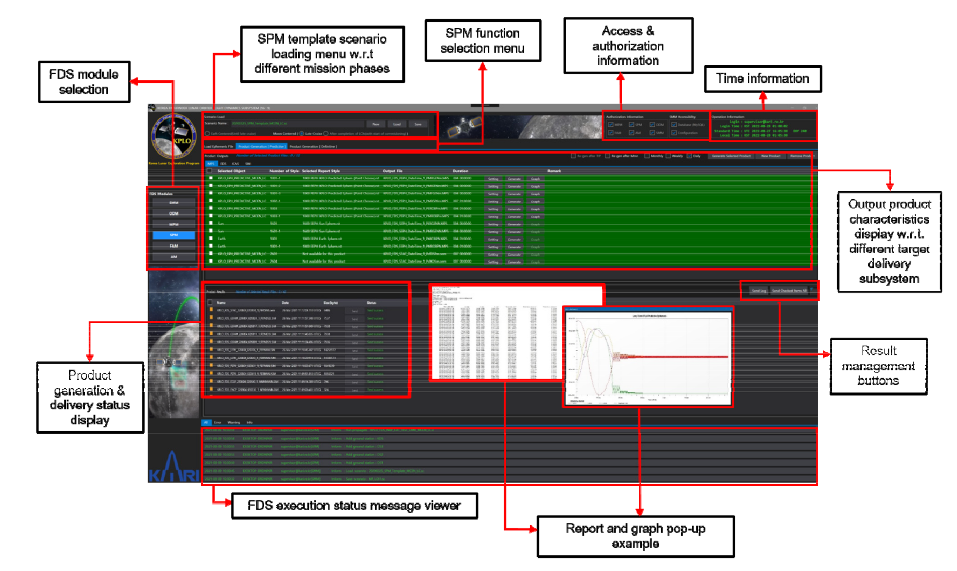
After completion of the template scenario loading, the operator can utilize both predictive and definitive product generation tabs, which are divided into two user-friendly screens, “Product output” and “Product result”. In the “Product output” screen, there are sub-tabs named with the target subsystem where the generated products are to be delivered. These sub-tabs are automatically named and linked with the list of target destinations registered in SMM. On the “Product output” screen, information on the selected product ID, report style, file naming convention, etc., is displayed. In addition, when the operator clicks the setting button, the characteristics of the product to be generated (already configured through xml) are summarized and shown, and the operator can generate the product or graph by clicking the generate or graph buttons. Although it is possible to generate each product individually, SPM also provides a function to check the desired product and generate the checked product at once. When an operator produces a product, the generated products are sequentially displayed on the screen below, namely, “Product output”. The operator can reconfirm the products produced on this screen and send them to the target subsystem by pressing the “send” button. At this time, if the transmission is successful, the color of the send button changes to green, and the text is also changed to a send success. Of course, the operator can select multiple products to send, and it also provides a function to send the selected products at once. In addition, SPM provides a function that allows one to search and manage the history of what products were delivered at any time in the past and whether or not the transmission was successful. Figure 14 shows the GUI of the product generation tab of SPM and shows the graph and output products in text format that are created together during the execution of SPM.

4.2.5. Fuel Accounting Module (FAM)

As the module name indicates, FAM estimates the fuel usage of the KPLO during the operation and generates and delivers the relevant product to other FDS submodules or other subsystems. Because the WSB/BLT method is selected for the KPLO mission, estimating the amount of remaining fuel during the flight is relatively important due to the nature of the WSB/BLT trajectory, which is quite sensitive to the magnitude of imparted Δ Vs . To predict the remaining fuel as accurately as possible, FAM will utilize the pressure, volume, temperature (PVT), and thrust on time (ToT) methods for fuel gauges, as well as related parameter estimation during the flight operation of the KPLO.
As is well known, the PVT method uses the ideal gas law to estimate a fuel volume based on telemetry temperature and pressure, and it has the characteristics that the accuracy of the estimated fuel volume depends on the precision of the propellant tank volume, the pressure, the temperature sensor, helium mass, etc. However, the accuracy of the estimated fuel mass using the PVT method will decrease when the amount of fuel in the tank decreases [45]. The ToT method, sometimes called the bookkeeping method, relies on the accuracy of the thruster flow rate. Therefore, uncertainty results directly from the uncertainty in the flow rate during engine and thruster firings and thus requires exact knowledge of all thruster on-times and pulse widths and an exact thrust and flow rate through the engines [45]. To calculate the amount of fuel, the PVT method will be used as the main method. However, to calculate the exact amount of fuel through the PVT method, a settling time longer than a certain period is required. Therefore, the ToT method will be used in parallel and used in FAM. Using ToT, each Δ V component, the total amount, and the start and end times of the maneuvers will be calculated using KPLO telemetry immediately after the maneuver execution. The parameters estimated using the ToT method can be passed to the ODM and will be used as an initial value for the process of performing OD with maneuvers. This may ease the convergence performance of OD that is performed immediately after maneuver execution. To provide more flexibility, FAM is also designed to provide a function to select a standard fuel gauging method, either PVT or ToT, or by the operator. Of course, the operator’s decision on which method to apply will differ for phases of the mission or according to the characteristics of the burn performed. In addition, the operator can type in the current fuel estimates by analyzing past trends in fuel consumption. To perform related functions, FAM provides the function of loading and processing PVT or ToT telemetry, creating related products, analyzing through graphs, and transferring the generated products to other target subsystems through FTP.
Every day, the current fuel mass of the KPLO will be accumulated and recorded in the file and will be transmitted to each subsystem that requires the relevant file. The current fuel mass estimate, Isp, mass flow, and thrust level of each thruster will also be estimated and will be delivered to the FDS database in the SMM to be updated and used for further burn planning. 
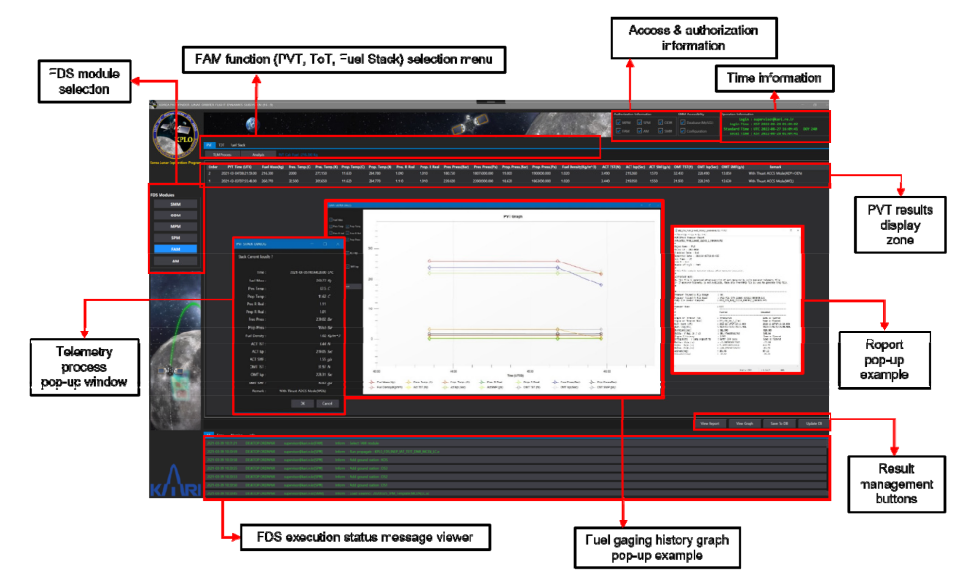
Figure 15 shows the GUI of the PVT tab among the functions of the FAM module. In addition, the GUI that pops up when the PVT function is performed or the generated output files, were captured separately and overlapped with Figure 15.

4.2.6. Analysis Module (AM)

The main objective of AM is to perform miscellaneous analyses to support the FDS operator. To enable the operator to actively respond to various demands while operating FDS, the following tools or functions are implemented through AM. 
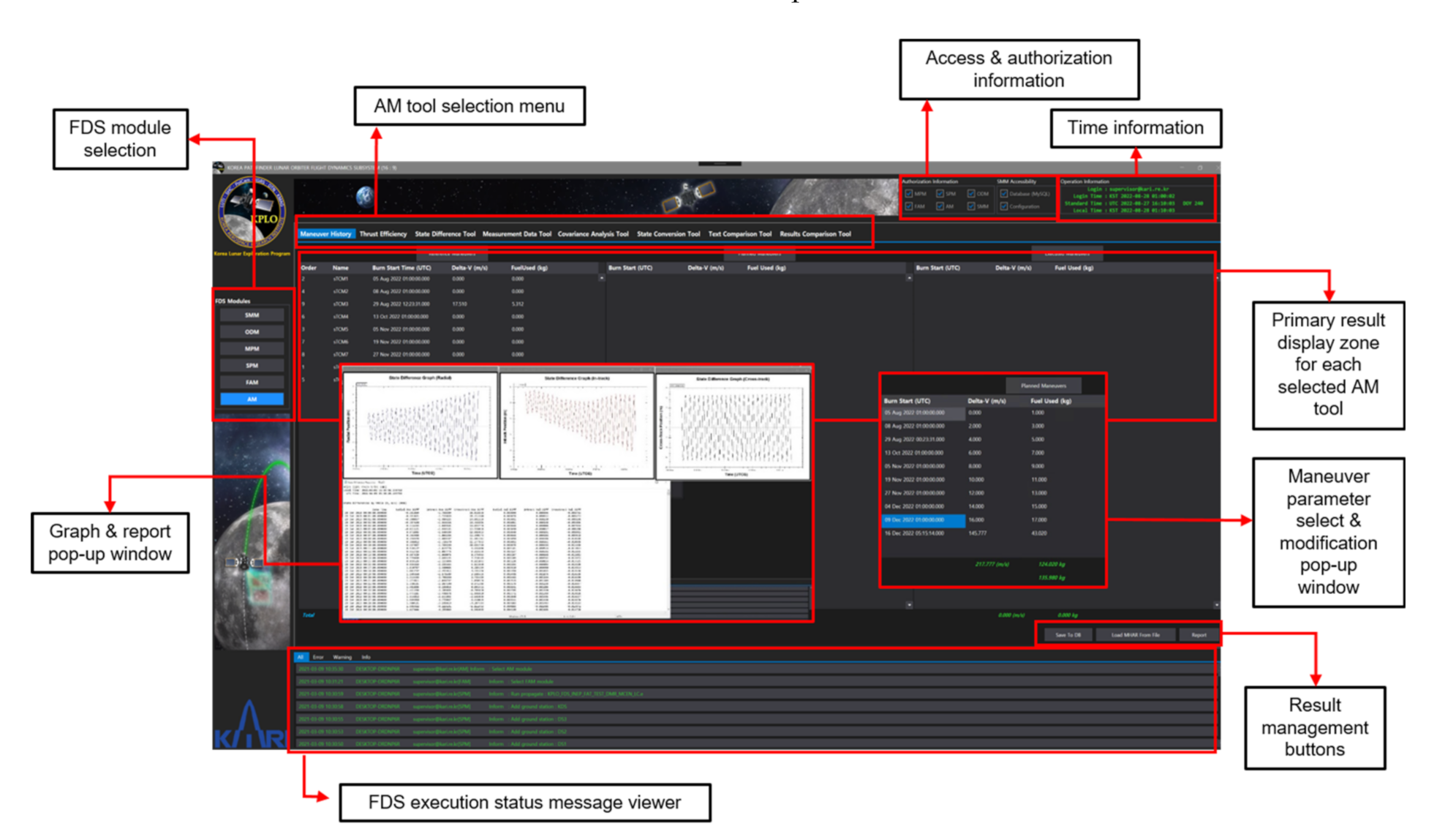
Figure 16 shows the GUI of maneuver history function, among the main functions of AM to be described below.
-
Maneuver history
The maneuver history tool is designed to allow for a comparison of major maneuver parameters, such as the burn start time, the burn duration, the magnitude of Δ V , the mass of fuel used, etc., for each maneuver, between the reference and the executed maneuvers. The reference maneuver values are predicted values during the trajectory design, and the planned values are obtained during the actual maneuver planning operation in MPM using the definitive ephemeris from the ODM and the updated engine model from the FAM and AM. The executed values are achieved from the telemetry data. By using this function, the operator can continuously manage and monitor parameters related to the maneuvers during the actual flight in comparison to the values that are predicted at the trajectory design phases.
-
Thrust efficiency
Through the thrust efficiency function, the FDS operator can estimate the thrust efficiency of each maneuver. Within the thrust efficiency function, it is possible to compare the thrust efficiency before and after each burn, and the FDS database inside of the SMM is updated based on the estimated thrust efficiency. The updated thrust efficiency is applied for the next maneuver planning inside of the MPM. The thrust efficiency function also includes a function to generate various text data files and graphs related to the predicted thrust efficiency.
-
State difference tool
The state difference tool provides the operator to compare the various formats of ephemeris written in STK internal (.e) or orbit ephemeris (.oem) formats. The operator can select reference and target ephemeris files to be compared and can generate state difference reports associated with those files. Inside the state difference report, difference statistics are reported, including RMS and the Min. and Max. values of the position and velocity vectors compared in radial, in-track, and cross-track components. The operator can set up units to be reported, i.e., cm and cm/s, and can also utilize graphs for easy analysis.
-
Measurement data tool
The measurement data tool uses prewritten template scenarios in ODTK to perform a given function. Through the loading of template scenarios, the measurement data tool supports the operator in performing various editing of the measurement data. As the KPLO mission will use measurement data in the TDM format as a basis, the raw measurement data in TDM format can be loaded, and the operator can select which files, as well as which contents, to be edited. Moreover, the measurement data tool provides a function that prints the graph of the measurement times vs. its type or vs. the tracker so that the operator can easily analyze the data.
-
Covariance analysis tool
The covariance analysis tool has a function to support the covariance analysis of the KPLO trajectory or orbit data, as is predictable from the name. Similar to the measurement data tool, the covariance analysis tool uses its predefined template scenario with ephemeris files in STK internal (.e) that contains covariance information. With this tool, the operator can perform analysis on covariance statistics in radial, in-track, and cross-track components, as with 3D total values. Additionally, the covariance analysis tool provides a very powerful 3D visualization of the covariance ellipsoid to support the operator’s analysis.
-
State conversion tool
Using the state conversion tool, it is possible to reprocess ephemeris generated in FDS. For example, the coordinate frame can be converted from/to with different central bodies with different reference axes, the time format can be transformed to suit the requestor’s preferences, and the state representation can be transformed, such as between Cartesian and orbital elements.
-
Text comparison tool
The text comparison tool provides convenience for the FDS operator to make a direct comparison of two files. When the operator selects two products, the text comparison tool compares each product and changes the text color of the different parts in order to improve readability.
-
Results comparison tool
The main function of the results comparison tool is to provide convenience so that the operator can grasp the differences between two different FDS-generated products at a glance. When the operator selects two different FDS-generated products, it not only plots each content of the product, but also has the function of calculating the difference between them and shows the results within plots, as well as text files.

5. Flight Operation Preparation

For the success of the KPLO mission, KARI and NASA signed an agreement in 2016 that the KPLO will carry one NASA science payload under NASA collaboration in telecommunications, navigation, and mission design for the KPLO mission. Therefore, many collaborative efforts are currently devoted to the successful launch and operation of the KPLO led by a KARI team. KARI is now working closely with the NASA JPL regarding transfer trajectory design, especially WSB/BLT trajectory design, and DSN activities. In the case of the WSB/BLT trajectory design, cooperation was achieved in such a way that JPL compared the results obtained using their design tools when KARI proceeded with the trajectory design first. With the NASA Johnson Space Center (JSC), KARI is coworking on nominal mission orbit design and analysis, and further flight dynamics-related operation of KPLO will be partially assisted by JSC. For the nominal mission orbit design, the ShadowCam requirements were passed on to the KARI trajectory design team through regular meetings with JSC, and the mission orbit was designed and modified by the KARI team to reflect the delivered requirements. The modification results were then verified through a joint analysis and advice from not only JSC, but also the GSFC working with the ShadowCam team.
For the successful operation of KPLO FDS, KARI is currently preparing a template scenario to be used in each module in the FDS for each mission phase. There are four different template scenarios to be used inside the ODM during operation. The first one is to be used during the TLC phase, the second one is generated to be used in the late cruise phase where the central body is changed from the Earth to the Moon, the third one is for LOI burns, and finally, a template scenario for the phase of orbiting around the Moon. For the MPM, several sets of OTTS are now in preparation, which are again classified according to the mission phases, namely, the Earth-centered phase or the Moon-centered phase. Regardless of the expression of the central body of KPLO, the OTTS to be used in the MPM can again be subclassified based on the timeline of each maneuver during the mission. In addition, another set of template scenarios for QC and MR for every maneuver that is planned during the flight of KPLO are being prepared. For the aspect of trajectory contingency situations, trajectory design for contingency situations is prepared along with the generation of CTTS considering interoperability with FDS. Even though not all contingency situations can be predicted, as many contingency situations as possible are now being predicted, and relevant CTTS are in preparation to be loaded inside of the FDS. The template scenario to be used in the SPM module consists of a total of three scenarios: One is with the template scenario that has an Earth-centered mission phase, and the other two scenarios with the lunar-centered scenario are named the late cruise phase and the start from commissioning phase. Using the aforementioned template scenarios for each mission phase, various products required by other subsystems are currently being created and tested for mutual compatibility. Although we have prepared for various possibilities that may occur during actual operation, there may be problems with the template scenario in actual operation. Therefore, KPLO FDS prepared an additional function that simply loads the STK scenario; that is, it does not perform any function using FDS, but creates various products in the format of FDS using STK’s default report style and internal API. This function is the last hold on KPLO’s actual operation and will be very useful in the case of an FDS emergency itself.
In addition to preparing a template scenario for a successful FDS run, various efforts are being made between KARI and JSC for the successful flight operation of KPLO. The format of the data product to be exchanged between each institution is now being checked, and transmission/reception tests are now also being conducted. In addition, qualitative tests on the data contents are being conducted with great care. Repeated tests (FDS simulations using each institution’s flight dynamics software) between KARI and JSC are expected to continue, and by conducting rehearsals together, the chances of success of the KPLO mission will be increased.

6. Lessons Learned

In the absence of in-depth relevant references, the design, development, and operational preparation of the FDS for the lunar mission has been very challenging. KARI was able to learn many lessons through numerous trials and errors during the past several years, and the most important lessons among them are as follows.
-
Interoperability regarding trajectory or orbit design results
Unlike typical LEO and GEO satellite missions, the FDS design, development, and operation preparation of the KPLO mission required a very high complementary relationship between the FDS and trajectory or orbit design results. Therefore, KARI made a choice to prepare TDS and maintaining interoperability with FDS. This design philosophy enabled to operate KPLO not only regarding the characteristics of interplanetary trajectory design work, which can only be designed by a subject matter expert, but also securing the operational stability of the FDS itself.
-
The flexibilities on maneuver target parameter selection
In the early design of KPLO FDS, various maneuver target parameters, as well as the GUI design, were fixed in accordance with the 3.5 phasing orbit transfer strategy. However, due to the mass problem of KPLO, the transfer method was changed from 3.5 phasing to WSB/BLT. Therefore, a major redesign of the FDS was unavoidable. While redesigning the FDS, one of the top priorities considered was to automatically detect the activated parameters inside of the template scenario and to only display those parameters in the GUI of the FDS. This effort resulted in the maximization of FDS applicability to any situation that may occur during the real-time operation. This design strategy also resulted in a very effective response to the establishment of operational preparation for a contingency trajectory situation during actual flight operations.
-
Management of FDS deliverables
Among the components of KGDS, FDS creates the most products and delivers them to other subsystems. Each and every subsystem that receives the product of FDS requested various formats, i.e., different generation cycles, product duration with steps, etc. Accordingly, FDS needs a considerable amount of time to generate all of those products. The next-generation FDS for planetary mission developed by KARI may likely be to generate only the ephemeris files in the CCSDS oem format and deliver them to other subsystems. The received ephemeris files then can be reformatted to meet each of the subsystem’s own needs.
-
Sharing common understandings for flight operation preparation
The need to share common understandings among flight dynamics-related members and all members involved in the KPLO mission can never be overemphasized. Common knowledge sharing is even more critical when the joint international effort is devoted. This is because definitions that seem too reasonable are often used differently among different institutions. Mutual understanding can be enhanced through the preparation of various interface control documents. Those interface control documents may include any content that is necessary to enhance mutual understandings, and contents are recommended to be written as detailed as possible and should be shared with updates.

7. Conclusions

This paper addressed the design and implementation results of the FDS, which are essential for the successful flight operation of Korea’s first lunar probe, the KPLO. An overview of the KPLO payloads, bus system and mission trajectory, and KDGS were also briefly discussed. The design baseline of the KPLO FDS was established to reflect the characteristics of space exploration missions, especially lunar exploration. In particular, the interoperability and operational efficiency with the TDS, as well as the operational safety of FDS were considered as top priorities. This design philosophy and approach are significantly different from those of the existing FDS design and the operation strategy of general LEO and GEO missions. Considering the importance of Korea’s first lunar exploration mission, FDS based on COTS was designed and implemented. However, at the same time, core flight dynamics software based on KARI’s in-house algorithm is being developed in parallel for Korea’s further space exploration missions. The performance of the developed in-house software will also be validated using real navigation and flight data from the KPLO. To be faithful to the established design philosophy, the KPLO FDS, consisting of a total of six modules, was nested inside of the FDS, and each module was implemented to perform its own special and unique functions. The six major functional modules include SMM, ODM, MPM, SPM, FAM, and AM. The design of the GUI and mutual workflow of these modules were completed and implemented considering operator convenience as well as maximization of operational safety of the FDS. In particular, measures to supplement the malfunction of the FDS itself were assumed, and countermeasures were reflected. In addition to the development and implementation of FDS, many efforts are being devoted to preparing the flight dynamics operation of the KPLO. Numerous sets of OTTSs are currently being prepared to address nominal operation cases, and CTTSs are being prepared to the greatest extent possible for flight contingency situations. In addition to these efforts, numerous KARI and NASA engineers are putting significant effort, as a joint team, into the successful launch and flight operation of KPLO. Several flight dynamics-related simulations between KARI and NASA teams are underway, and shortly, KARI and NASA will continue to cooperate for the successful operation of the KPLO by conducting joint rehearsals. The results of this paper will provide much inspiration to various communities designing and implementing FDS for future space exploration missions and preparing for flight dynamics-related operations.

Author Contributions

Y.-J.S. took the lead in writing the manuscript with support from Y.-R.K. and J.B., Y.-R.K. wrote the part describing the orbit determination module and J.B. wrote the part describing the maneuver planning module. Interfaces with trajectory design system as well as template scenario preparation parts were reviewed and commented by J.-i.P., S.H. and D.L. Project administration and funding acquisition were done by D.-K.K. All authors provided critical feedback and helped shape the manuscript. All authors have read and agreed to the published version of the manuscript.

Funding

This work was supported by the KARI (under a contract with the Ministry of Science and ICT) through the “Development of Pathfinder Lunar Orbiter and Key Technologies for the Second Stage Lunar Exploration” project (no. 2016M1A3A9005561).

Institutional Review Board Statement

Not applicable.

Informed Consent Statement

Not applicable.

Acknowledgments

Special thanks are extended to Pohlkamp, Kara M., Myrmo, Elias K., Fuller, Shane, Stuit, Timothy, and Snook, Bryan E. and Condon, Gerald L. at NASA/JSC, Roncoli, Ralph B. and Chung, Min-kun at NASA/JPL, and Mesarch, Michael A. at NASA/GSFC for their thoughtful comments, suggestions, and efforts on KPLO project. We would like to also thank the rest of KARI and NASA colleagues for their hard work and supports.

Conflicts of Interest

The Authors declare that there are no conflict of interest regarding the publication of this paper.

References

  1. Korea Aerospace Research Institute. Available online: https://www.kari.re.kr/eng/sub01_04.do (accessed on 12 May 2021).
  2. Song, Y.-J.; Lee, D.; Bae, J.; Kim, Y.-R.; Choi, S.-J. Flight Dynamics and Navigation for Planetary Missions in Korea: Past Efforts, Recent Status, and Future Preparations. J. Astron. Space Sci. 2018, 35, 119–131. [Google Scholar]
  3. Shin, S.; Heo, H.P.; Choi, S.W.; Ko, H. The Lunar terrain imager operations concepts. In Proceedings of the 2018 SpaceOps Conference, Marseille, France, 28 May–1 June 2018. [Google Scholar]
  4. Sim, S.K.; Kim, S.S.; Jeong, M.; Choi, Y.J.; Shkuratov, Y.G. Observational Strategy for KPLO/PolCam Measurements of the Lunar Surface from Orbit. Publ. Astron. Soc. Pac. 2020, 132, 015004. [Google Scholar] [CrossRef]
  5. Kim, K.; Min, K.W.; Elphic, R.; Yi, R.C.; Hasebe, N.; Hiroshi, N.; Park, J.; Yi, E.S.; Lee, S.; Yeon, Y.K.; et al. Introduction to the lunar gamma-ray spectrometer for Korea pathfinder lunar orbiter. In Proceedings of the 42nd COSPAR Scientific Assembly, Pasadena, CA, USA, 14–22 July 2018. [Google Scholar]
  6. Lee, H.; Jin, H.; Jeong, B.; Lee, S.; Lee, S.; Baek, S.M.; Shin, J.; Lee, J.K.; Park, H.; Kim, K.H.; et al. KMAG: KPLO Magnetometer Payload. Publ. Astron. Soc. Pac. 2021, 133, 034506. [Google Scholar] [CrossRef]
  7. Robinson, M.S.; ShadowCam Team. ShadowCam: Seeing in the Shadows. In Proceedings of the Lunar Polar Volatiles, Laurel, MD, USA, 7–9 August 2018. [Google Scholar]
  8. Jo, J.H.; Lee, B.S.; Ahn, J.Y. Space internet development for Korean lunar exploration. In Proceedings of the 14th International Conference on Space Operations, Daejeon, Korea, 16–20 May 2016. [Google Scholar]
  9. National Aeronautics and Space Administration. Available online: https://www.nasa.gov/feature/nasa-selects-nine-scientists-to-join-korea-pathfinder-lunar-orbiter-mission (accessed on 27 May 2021).
  10. Parker, J.S.; Anderson, R.L. Low-Energy Lunar Trajectory Design. In JPL Deep-Space Communications and Navigation Series; John Wiley & Sons: Hoboken, NJ, USA, 2014. [Google Scholar]
  11. Lee, D.; Park, J.I.; Song, Y.J.; Kim, Y.R.; Hong, S.B.; Bae, J.; Kim, D.K.; Lee, S.R. KPLO BLT trajectory design. In Proceedings of the KSAS Spring Conference, Goseong, Korea, 8–10 July 2020. [Google Scholar]
  12. Park, J.I.; Lee, D.; Kim, Y.R.; Song, Y.J.; Hong, S.B.; Bae, J.; Kim, D.K.; Lee, S.R. Lunar orbit insertion and mission orbit design for KPLO BLT trajectory. In Proceedings of the KSAS Spring Conference, Goseong, Korea, 8–10 July 2020. [Google Scholar]
  13. Lee, D.; Park, J.I.; Song, Y.J.; Kim, Y.R.; Hong, S.B.; Bae, J.; Kim, D.K.; Lee, S.R. WS.B/BLT trajectories for the KPLO mission. In Proceedings of the KSSS Fall Conference, Jeju, Korea, 28–30 October 2020. [Google Scholar]
  14. Park, J.I.; Lee, D.; Hong, S.B.; Song, Y.J.; Kim, Y.R.; Bae, J.; Kim, D.K.; Lee, S.R. KPLO lunar mission orbit design using eccentricity-argument of periapsis vector. In Proceedings of the KSSS Fall Conference, Jeju, Korea, 28–30 October 2020. [Google Scholar]
  15. Lee, D.; Park, J.I.; Song, Y.J.; Kim, Y.R.; Hong, S.B.; Bae, J.; Kim, D.K.; Lee, S.R. Lunar orbit conditions to design WS.B/BLT trajectories. In Proceedings of the KSAS Fall Conference, Jeju, Korea, 18–20 November 2020. [Google Scholar]
  16. Kim, Y.R.; Song, Y.J.; Bae, J.; Choi, S.W. Observational Arc-Length Effect on Orbit Determination for KPLO Using a Sequential Estimation Technique. J. Astron. Space Sci. 2018, 35, 295–308. [Google Scholar]
  17. Kim, Y.R.; Song, Y.J. Observational Arc-Length Effect on Orbit Determination for KPLO in the Earth-Moon Transfer Phase Using a Sequential Estimation. J. Astron. Space Sci. 2019, 36, 293–306. [Google Scholar]
  18. Kim, Y.R.; Song, Y.J.; Bae, J.; Choi, S.W. Orbit determination simulation for Korea pathfinder lunar orbiter using sequential estimation approach. In Proceedings of the 29th AAS/AIAA Space Flight Mechanics Meeting, Maui, HI, USA, 13–17 January 2019. [Google Scholar]
  19. Kim, Y.R.; Song, Y.J.; Park, J.I.; Bae, J.; Lee, D.; Hong, S.B.; Kim, D.K.; Lee, S.R. Orbit determination and prediction simulation of KPLO BLT trajectory. In Proceedings of the KSAS Spring Conference, Goseong, Korea, 8–10 July 2020. [Google Scholar]
  20. Kim, Y.R.; Song, Y.J.; Park, J.I.; Lee, D.; Bae, J.; Hong, S.B.; Kim, D.K.; Lee, S.R. Orbit determination simulation for Korea pathfinder lunar orbiter using ballistic lunar transfer. In Proceedings of the 2020 AAS/AIAA Astrodynamics Specialist Conference, South Lake Tahoe, CA, USA, 9–13 August 2020. [Google Scholar]
  21. Kim, Y.R.; Hong, S.B.; Song, Y.J.; Park, J.I.; Bae, J.; Lee, D.; Kim, D.K.; Lee, S.R. Orbit determination error analysis for design of launch vehicle dispersion trajectory correction maneuver. In Proceedings of the KSAS Fall Conference, Jeju, Korea, 18–20 November 2020. [Google Scholar]
  22. Kim, Y.R.; Song, Y.J.; Park, J.I.; Lee, D.; Bae, J.; Hong, S.B.; Kim, D.K.; Lee, S.R. Ground Tracking Support Condition Effect on Orbit Determination for Korea Pathfinder Lunar Orbiter (KPLO) in Lunar Orbit. J. Astron. Space Sci. 2020, 37, 237–247. [Google Scholar]
  23. Kim, Y.R.; Song, Y.J.; Bae, J.; Park, J.I.; Hong, S.B.; Kim, D.K.; Lee, S.R. Ground tracking support condition effect on orbit determination and prediction for Korea pathfinder lunar orbiter for trans-lunar trajectory. In Proceedings of the KSSS Spring Conference, Yeosu, Korea, 28–30 April 2021. [Google Scholar]
  24. Song, Y.J.; Kim, Y.R.; Lee, D.; Park, J.I.; Hong, S.B.; Bae, J.; Kim, D.K.; Lee, S.R. Impact of OP errors to the KPLO lunar orbit insertion utilizing BLT. In Proceedings of the KSAS Spring Conference, Goseong, Korea, 8–10 July 2020. [Google Scholar]
  25. Bae, J.; Lee, D.; Song, Y.J.; Kim, Y.R.; Park, J.I.; Hong, S.B.; Kim, D.K.; Lee, S.R. Trajectory correction maneuver design of KPLO BLT trajectory considering flight operation. In Proceedings of the KSAS Spring Conference, Goseong, Korea, 8–10 July 2020. [Google Scholar]
  26. Hong, S.B.; Kim, Y.R.; Song, Y.J.; Lee, D.; Park, J.I.; Bae, J.; Kim, D.K.; Lee, S.R. Launch vehicle dispersion analysis of KPLO BLT trajectory. In Proceedings of the KSAS Spring Conference, Goseong, Korea, 8–10 July 2020. [Google Scholar]
  27. Bae, J.; Hong, S.B.; Song, Y.J.; Kim, Y.R.; Park, J.I.; Lee, D.; Kim, D.K.; Lee, S.R. Trajectory correction maneuver analysis of KPLO WS.B/BLT trajectory with respect to burn error and maneuver execution epoch. In Proceedings of the KSAS Fall Conference, Jeju, Korea, 18–20 November 2020. [Google Scholar]
  28. Bae, J.; Kim, Y.R.; Song, Y.J.; Park, J.I.; Hong, S.B.; Lee, D.; Kim, D.K.; Lee, S.R. Maneuver recovery function development and result analysis of trajectory correction maneuver of Korea pathfinder lunar orbiter. In Proceedings of the KSSS Fall Conference, Jeju, Korea, 28–30 October 2020. [Google Scholar]
  29. Hong, S.B.; Park, J.I.; Kim, I.K.; Song, Y.J.; Kim, Y.R.; Bae, J.; Lee, D.; Kim, D.K.; Lee, S.R. KPLO ground station tracking time analysis. In Proceedings of the KSSS Fall Conference, Jeju, Korea, 28–30 October 2020. [Google Scholar]
  30. Song, Y.J.; Lee, D.; Bae, J.; Kim, Y.R.; Park, J.I.; Hong, S.B.; Kim, D.K.; Lee, S.R. Mission coordinate system definition, precise transformation algorithm and its implementation results for Korea pathfinder lunar orbiter flight dynamics. In Proceedings of the KSSS Fall Conference, Jeju, Korea, 28–30 October 2020. [Google Scholar]
  31. Song, Y.J.; Jeon, M.J.; Bae, J.; Kim, Y.R.; Park, J.I.; Hong, S.B.; Kim, D.K.; Lee, S.R. Fuel gauging methods for flight operation of Korea pathfinder lunar orbiter mission. In Proceedings of the KSSS Spring Conference, Yeosu, Korea, 28–30 April 2021. [Google Scholar]
  32. Bae, J.; Kim, Y.R.; Song, Y.J.; Park, J.I.; Hong, S.B.; Kim, D.K.; Lee, S.R. Maneuver recovery process of lunar orbiter insertion maneuver considering engine model for Korea pathfinder lunar orbiter. In Proceedings of the KSSS Spring Conference, Yeosu, Korea, 28–30 April 2021. [Google Scholar]
  33. Carrico, J.; Fletcher, E. Software architecture and use of satellite tool kit’s astrogator module for liberation point orbit mission. In Proceedings of the Libration Point Orbits and Applications Conference, Aiguablava, Spain, 10–14 June 2003. [Google Scholar]
  34. Lee, B.S.; Lee, J.S.; Won, C.H.; Eun, J.W.; Lee, H.J. Flight Dynamics Support for the KOMPSAT in Launch and Early Orbit Phase Operation. Bull. Korean Astron. Soc. 1999, 24, 83. [Google Scholar]
  35. Lee, B.S.; Hwang, Y.; Kim, H.Y. Automation of the flight dynamics operations for low earth orbit satellite mission control. In Proceedings of the International Conference on Control, Automation and Systems, Seoul, Korea, 14–17 October 2008. [Google Scholar]
  36. Jung, O.C.; Chung, D.W.; Park, S.J.; Hyun, D.W.; Chun, Y.S. Advanced concept and design of the multi-satellite operations System. In Proceedings of the SpaceOps 2010 Conference, Huntsville, AL, USA, 25–30 April 2010. [Google Scholar]
  37. Lee, B.S.; Hwang, Y.; Kim, H.Y.; Kim, J. Design and Implementation of the Flight Dynamics System for COMS Satellite Mission Operations. Acta Astronaut. 2011, 68, 1292–1306. [Google Scholar] [CrossRef]
  38. Hwang, Y.; Lee, B.S.; Kim, Y.R.; Roh, K.M.; Jung, O.C.; Kim, H. GPS-Based Orbit Determination for KOMPSAT-5 Satellite. ETRI J. 2011, 33, 487–496. [Google Scholar] [CrossRef]
  39. Lee, B.S.; Hwang, Y.; Kim, H.Y.; Kim, B.Y. Operational validation of the flight dynamics system for COMS satellite. In Proceedings of the 22nd International Symposium on Space Flight Dynamics, São José dos Campos, Brazil, 28 February–4 March 2011. [Google Scholar]
  40. Jung, O.C.; Choi, S.J.; Yoon, J.C.; Lee, B.S.; Hwang, Y.; Chung, D.W.; Kim, E.K.; Kim, H.J. Flight dynamics operation for KOMPSAT-5 LEOP. In Proceedings of the SpaceOps 2012 Conference, Stockholm, Sweden, 11–15 June 2012. [Google Scholar]
  41. Jung, O.C.; Yim, H.; Chung, D.W.; Kim, E.K. Comprehensive flight dynamics activities and enhancement for KOMPSAT-3 mission operations. In Proceedings of the SpaceOps 2014 Conference, Pasadena, CA, USA, 5–9 May 2014. [Google Scholar]
  42. Lim, H.S.; Park, J.H.; Kim, D.G. The GK2A/2B ground system after the COMS. In Proceedings of the SpaceOps 2016 Conference, Daejeon, Korea, 16–20 May 2016. [Google Scholar]
  43. Nickel, C.; Carrico, J.P., Jr.; Lebois, R.; Policastri, L.; Sherman, R. LADEE flight dynamics system overview. In Proceedings of the 25th AAS/AIAA Space Flight Mechancis Meeting, Williamsburg, VA, USA, 11–15 January 2015. [Google Scholar]
  44. The Consultative Committee for Space Data Systems. Recommendation for Space Data System Standards, Tracking Data Message; Recommended Standard. CCSDS 503.0-B-1 BLUE BOOK; CCSDS Secretariat: Washington, DC, USA, 2007. [Google Scholar]
  45. Yendler, B. Review of propellant gauging methods. In Proceedings of the 44th AIAA Aerospace Sciences Meeting and Exhibit, Reno, Nevada, USA, 9–12 January 2006. [Google Scholar]
Figure 1. KPLO spacecraft configuration: Solar array stowed (left) and deployed (right).
Aerospace 08 00222 g001
Figure 2. WSB/BLT transfer trajectory during the launch period and the LOA phase of the KPLO.
Aerospace 08 00222 g002
Figure 3. The top-level architecture of the KDGS.
Aerospace 08 00222 g003
Figure 4. KDSA foreground located at the Yeoju area in Korea.
Aerospace 08 00222 g004
Figure 5. Top level interoperability concept between the FDS and TDS.
Aerospace 08 00222 g005
Figure 6. Functional module architecture associated with the primary–redundant structure.
Aerospace 08 00222 g006
Figure 7. The first login screen of KPLO FDS (left) and the main screen of the SMM module (right).
Aerospace 08 00222 g007
Figure 8. Overall flowchart of KPLO FDS ODM.
Aerospace 08 00222 g008
Figure 9. The main screen GUI layout of the FDS ODM.
Aerospace 08 00222 g009
Figure 10. Maneuver planning workflow.
Aerospace 08 00222 g010
Figure 11. Maneuver recovery workflow.
Aerospace 08 00222 g011
Figure 12. The GUI for the consistency check function in MPM.
Aerospace 08 00222 g012
Figure 13. The quality check and associated product generation function GUI inside of MPM.
Aerospace 08 00222 g013
Figure 14. The GUI design of “product generation” tab in SPM.
Aerospace 08 00222 g014
Figure 15. The GUI design of the PVT function in FAM.
Aerospace 08 00222 g015
Figure 16. The GUI design of maneuver history function in AM.
Aerospace 08 00222 g016
Table 1. Summary of six different KPLO payloads.
PayloadsScience ObjectivesHosting Institutions
LUTI Aerospace 08 00222 i001
-
Geology, Topology of the lunar surface
-
Future landing site for the next lunar mission
KARI
PolCam Aerospace 08 00222 i002
-
Understanding space weathering process
-
Investigating internal evolution of the Moon
-
Supporting lunar landing site search
Korea Astronomy and Space Science Institute (KASI)
KGRS Aerospace 08 00222 i003
-
the elemental analysis of lunar surface materials within a gamma-ray energy range
-
Investigation on lunar geology and lunar resources
Korea Institute of Geoscience and Mineral Resources (KIGAM)
KMAG Aerospace 08 00222 i004
-
Measurement of lunar magnetic fields
KyungHee University (KHU)
DTNPL Aerospace 08 00222 i005
-
File transfer
-
Message exchange
-
Video streaming over DTN between KPLO & Ground
Electronics and Telecommunications Research Institute (ETRI)
ShadowCam Aerospace 08 00222 i006
-
Understanding of lunar polar volatiles, location, content, morphology
Arizona State University (ASU) and Malin Space Science Systems (MSSS)
Table 2. The software version used in KPLO FDS.
SoftwareVersion
Operating SystemWindow Server * 2 eaWindow Server 2019
Window 10 * 2 eaWindow 10 Pro ×64
CompilerVisual Studio * 2 eaVisual Studio 2015
COTSSTK with Astrogator12.1.0
ODTK7.1.1
Table 3. The key features for the KPLO FDS six modules.
ModulesKey FeaturesRemarks
SMM
-
Performs overall FDS system managements such as FDS module configuration, database setting, product delivery setting, user account management, and system log management, etc.
ODM
-
Performs orbit determination for entire mission phases including related measurement data processing. Have the ability to ingest tracking data for pre-processing and IOD and OOD with/without maneuvers can be performed.
Template scenario load
MPM
-
Have maneuver planning, quality check, maneuver recovery functions with detailed KPLO engine configuration. The MPM will utilize the “thruster sets” model to target desired mission trajectory for the upcoming first maneuver. Liquid settling burn will also be modeled if necessary.
Template scenario load
SPM
-
State vectors of the KPLO and mission-related orbital event can be predicted through SPM. Related data files will be generated and have the ability to deliver products that were requested by other subsystems.
Template scenario load
FAM
-
Estimates fuel usage of the KPLO and generates related data files. Current fuel estimate, Isp, mass flow, thrust level will be evaluated and updated from FAM.
AM
-
Miscellaneous analyses can be conducted inside of AM through several tools or functions to support the FDS operator.
Template scenario load (if necessary)
Publisher’s Note: MDPI stays neutral with regard to jurisdictional claims in published maps and institutional affiliations.

