Article

Numerical Evaluation of Structural Safety of Linear Actuator for Flap Control of Aircraft Based on Airworthiness Standard

1
Department of Integrated Systems Engineering, Hankyong National University, Anseong-si, Gyeonggi-do 17579, Korea
2
School of ICT, Robotics & Mechanical Engineering, Hankyong National University, Anseong-si, Gyeonggi-do 17579, Korea
*
Author to whom correspondence should be addressed.
Aerospace 2021, 8(4), 104; https://doi.org/10.3390/aerospace8040104
Submission received: 9 March 2021 / Revised: 1 April 2021 / Accepted: 5 April 2021 / Published: 7 April 2021
(This article belongs to the Special Issue Vibration Control for Space Application)

Abstract

:
Airworthiness standards of Korea recommend verifying structural safety by experimental tests and analytical methods, owing to the development of analysis technology. In this study, we propose a methodology to verify the structural safety of aircraft components based on airworthiness requirements using an analytical method. The structural safety and fatigue integrity of a linear actuator for flap control of aircraft was evaluated through numerical analysis. The static and fatigue analyses for the given loads obtained from the multibody dynamics analysis were performed using the finite element method. Subsequently, the margin of safety and vulnerable area were acquired and the feasibility of the structural safety evaluation using the analytical method was confirmed. The proposed numerical analysis method in this study can be adopted as an analytical verification methodology for the airworthiness standards of civilian aircraft in Korea.

1. Introduction

The flap of an aircraft is an auxiliary lift device on flight-control surfaces, which adjusts the lift force and velocity during take-off and landing to maintain stable fuselage attitude [1]. If the flap loses its function, the fuselage may lose maneuverability and cause a large accident [2,3]. Therefore, the Korean Airworthiness Standards (KAS) announced by the Ministry of Land, Infrastructure and Transport of South Korea (MOLIT) specifies that the flap should be securely fixed when it is at the required position in the flap-control system (KAS Part 23.697) and it should be designed not to cause a failure that may lead to unstable flight characteristics (KAS Part 23.701) [4].
The key component of the flap-control system is the flap actuator that controls the flap deflection angle and velocity while supporting the flap. Therefore, for stable flap control, overseas leading companies have conducted various studies to ensure the safety and reliability of the flap actuator [5]. Electro-mechanical actuators (EMAs), which, despite their light weight, have high efficiency and precise control performance, have been adopted as actuators for flap control of small aircraft to reduce the aircraft weight and provide high reliability [6]. For EMAs however, structural safety evaluation is required for the detailed parts of the actuator because power is transmitted through gears and screws, unlike conventional hydraulic actuators. Since mock-up tests require considerable cost and time, studies have been actively conducted to evaluate structural safety using a combination of analytical methods and mock-up tests to consider various factors related to aviation safety [7,8]. Since KAS of South Korea (KAS Part 23.305 and KAS Part 23.307) and directive no. 932 of MOLIT specify that safety should be verified by structural analysis, if there is an empirical foundation that has proven structural safety by an analytical method, the importance of analysis is increased [9,10]. Although studies have been actively conducted on the evaluation of the structural safety of flap actuators using numerical approaches, there remain insufficient technologies for fatigue evaluation [11,12]. Therefore, it is necessary to develop static analysis and fatigue evaluation techniques for aircraft flap actuators based on numerical analysis. Then, the cost and time required for the certification process for the structural safety of civil aircraft structures can be reduced. Moreover, the structural safety evaluation must be conducted by considering the external factors (temperature and loads) that are difficult to be considered in actual tests.
This study aimed to present static analysis and fatigue evaluation techniques based on numerical approaches for the linear actuator of small aircraft (general aviation (GA) class) under development for flap control. As part of this study, multibody dynamics (MBD) analysis was conducted on a test rig for the linear actuator with coil springs, and the axial load history of the actuator was calculated according to the flap deflection angle. Based on the calculated load, static analysis using finite element analysis (FEA) was conducted on the key components of the linear actuator, and structural safety was evaluated by deriving the margin of safety (MoS) of each component. In addition, based on the stress data calculated through the static analysis, FE-based fatigue analysis was conducted to evaluate fatigue safety.
The presented structural analysis techniques were proposed as methods for verifying the airworthiness standards (type design and type certification) of civil aircraft in South Korea using analytical techniques.

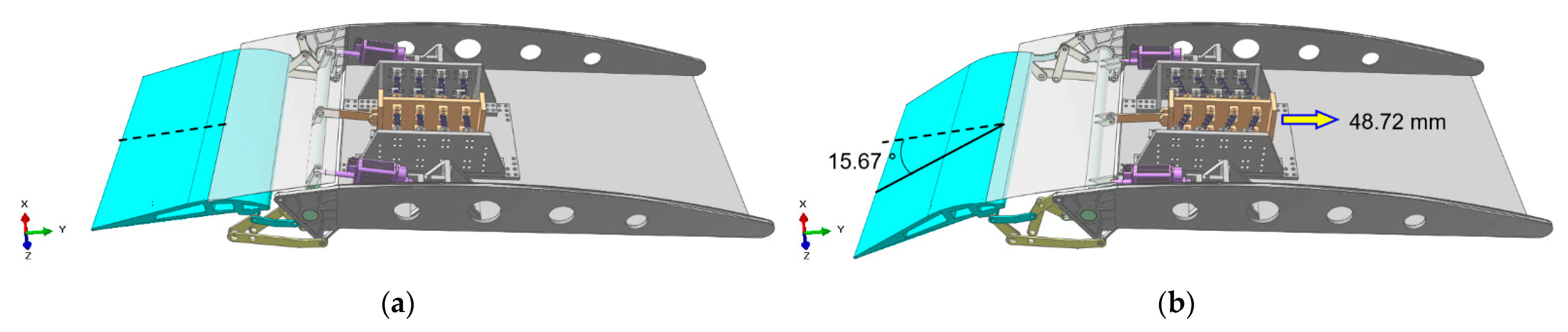
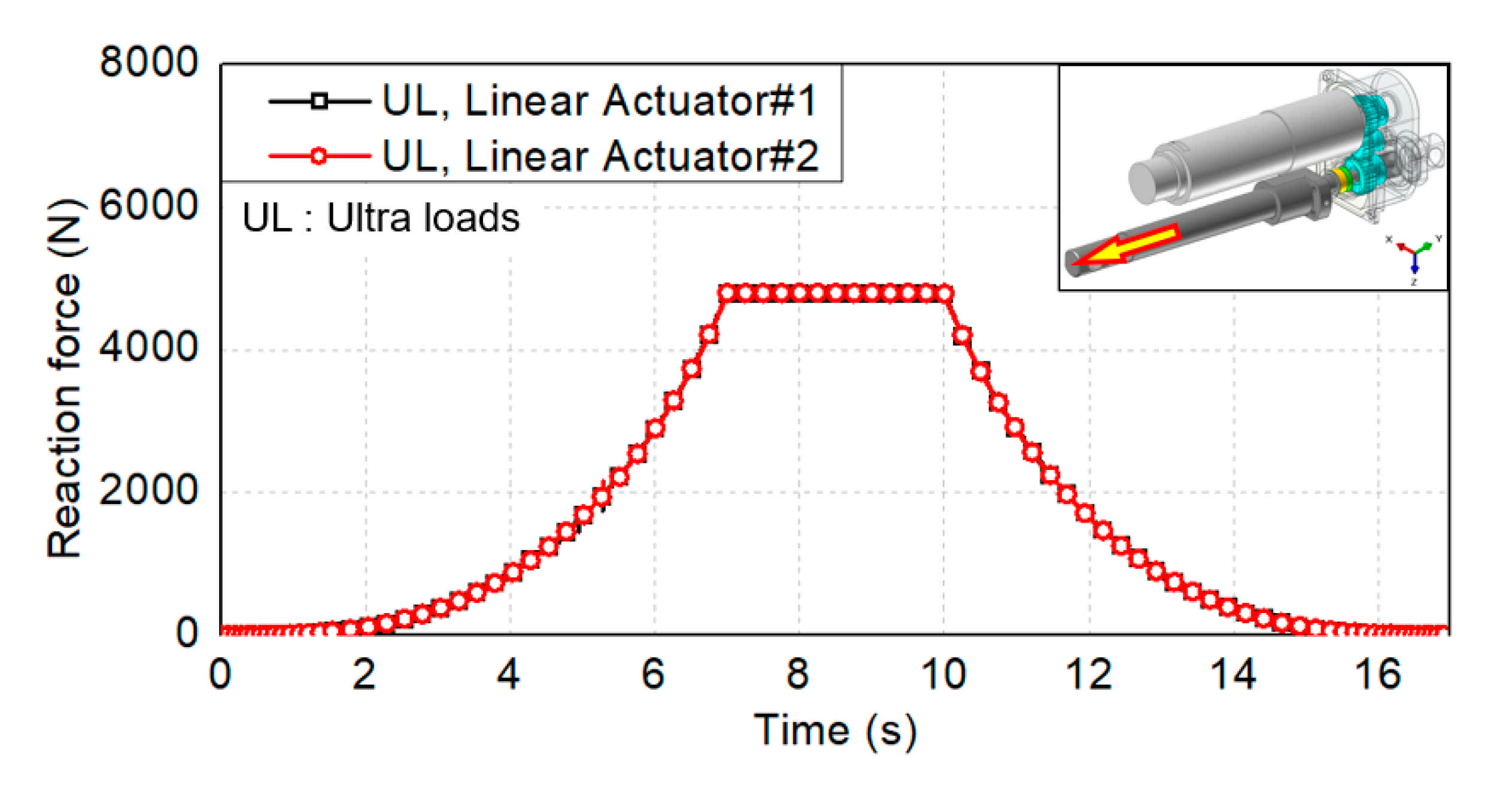
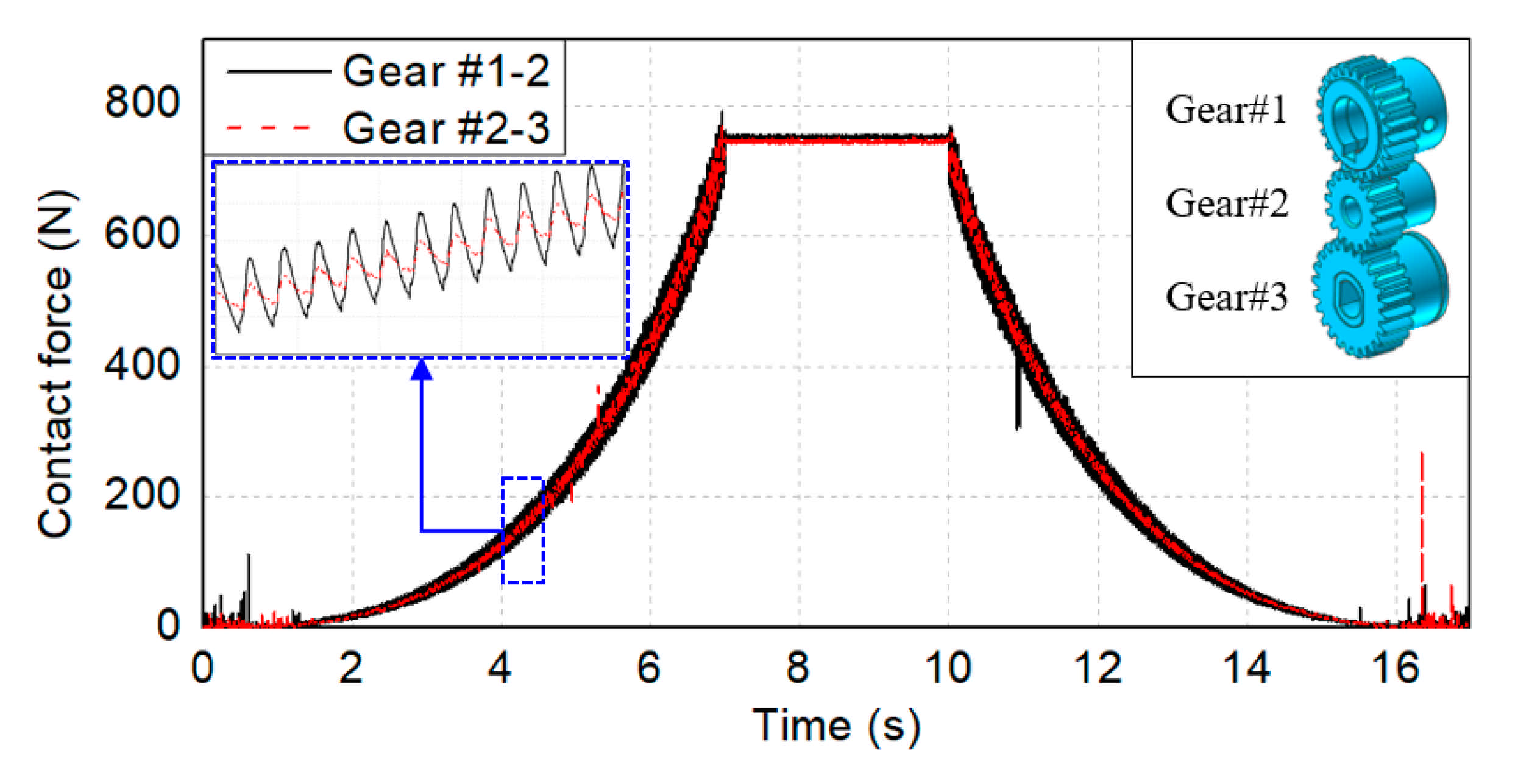
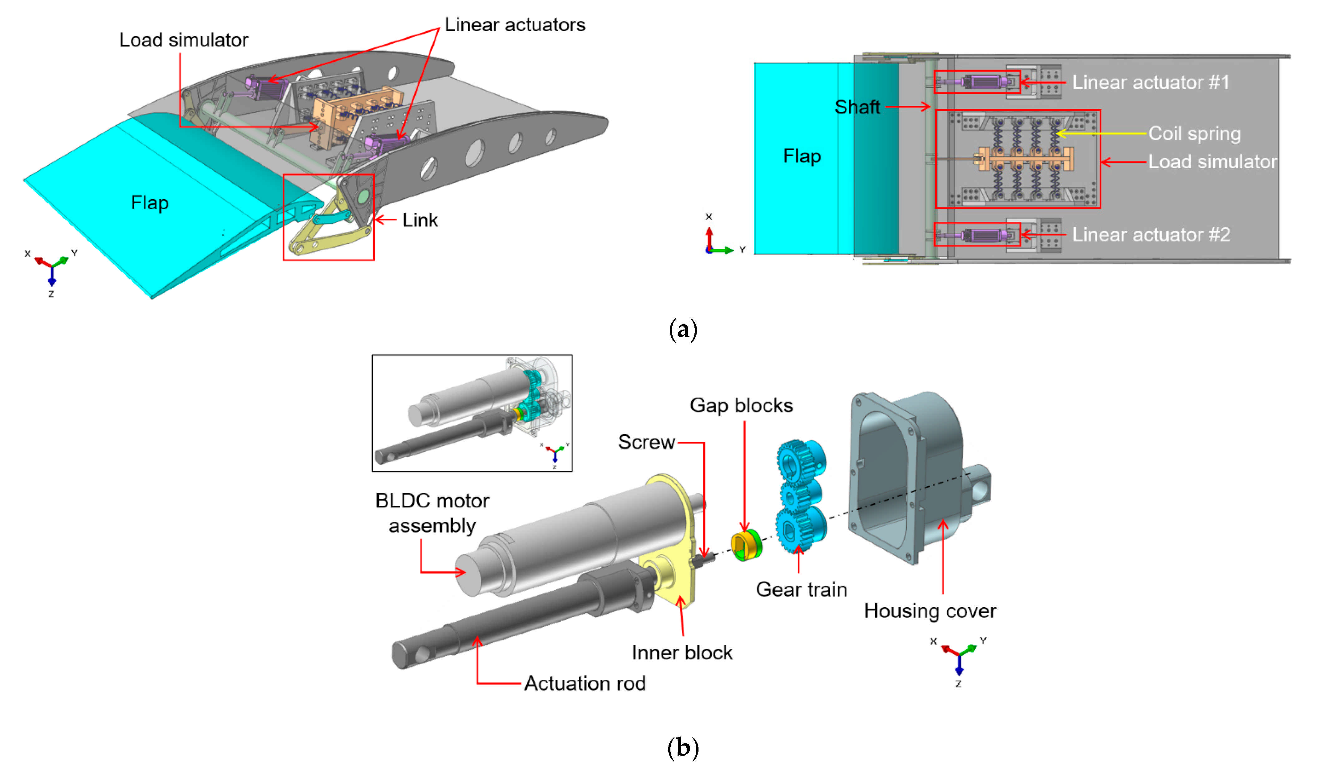
2. Multibody Dynamics Analysis

Figure 1 and Table 1 show the test rig and linear actuator models used for MBD analysis as well as the required specifications of the linear actuator. In this study, the required specifications of the EMA developed by Woodward MPC Inc. (Skokie, IL, USA) were adopted.
In the test rig, two linear actuators and a load simulator based on 16 coil springs were connected to the shaft, and the flap was controlled by the link as shown in Figure 1a. Concurrently, the flap deflection angle varied depending on the stroke of the linear actuator and the maximum axial load was applied to the actuator when the minimum stroke (0 mm) was reached. Therefore, the load applied to the linear actuator was determined by the spring constant of the coil springs. Meanwhile, the linear actuator transmitted the power of the brushless direct current (BLDC) motor to the actuation rod through the gear train with three spur gears and the ball screw as shown in Figure 1b.
For MBD analysis, joint and force conditions were used to reduce the analysis time by avoiding unnecessary contact conditions. The coil spring models were removed, and virtual spring forces were applied. Additionally, the pin model was replaced with a revolution joint, and a translation joint was applied to the actuation rod. In particular, the coupler joint was employed to simulate the linear motion of the actuation rod caused by the rotations of the screw [11].
From a perspective of the static analysis according to the airworthiness standards of South Korea, loads are divided into design limit loads (DLL; maximum load expected during operation) and ultimate loads (UL; a value obtained by multiplying DLL by a specified safety factor) (KAS Part 23.301) and the safety factor is set to 1.5 unless specified otherwise (KAS Part 23.303) [13]. In this study, structural safety was evaluated under the UL condition, and 4800 N (3200 N × 1.5) was set as UL according to the required specifications. The resulting coil spring constant is approximately 2253 N/mm. Figure 2 shows the operating profile of the linear actuator [14].
The initial stroke of the linear actuator is 70 mm, and the stroke reaches 0 mm in seven seconds, causing the flap surface to reach the maximum deflection angle (15.7°). After maintaining this condition for three seconds, the maximum stroke is reached again, and the flap deflection angle becomes 0° at 17 s.

3. Structural Analysis

3.1. Material Properties

Table 2 lists the mechanical properties of each component material used in the structural analysis. In this study, material tests (tensile and fatigue tests) and a literature survey were conducted to determine the mechanical properties of each component material of the actuator. The mechanical properties of AISI4340 and free-cutting brass were obtained from the literature [15,16]. Moreover, tensile tests on STS630 and AL7075 were conducted according to ASTM E8/E8M-16a and ASTM B557-15 standards [17,18], and fatigue tests were conducted according to ASTM E466-15 standard [19].
For conservative fatigue analysis in this study, probabilistic stress-life curves (P-S-N curves) were derived using the fatigue test results while Equations (1) and (2) were used only for the materials whose mechanical properties were obtained through material tests (STS630 and AL7075) [20].
log N f = α β log S
log N f = α β log S σ log N f
where N f and S are the fatigue life and applied stress, respectively.
The intercept ( α ) and slope ( β ) of the logarithmic coordinate system were calculated using the S-N curves derived from the fatigue tests and Equation (1), and the P-S-N curves were derived from the standard deviation of the fatigue life ( σ log N f ) corresponding to the arbitrary failure probability P (%) and Equation (2). Figure 3 shows the P-S-N curves derived for the failure probabilities of 50% and 1%. As shown in Figure 3, the intercept and slope of the logarithmic coordinate system were found to be 41.945 and 12.771 for the STS630, and 19.239 and 6.144 for the AL7075, respectively. Additionally, fatigue strengths that satisfy the failure probability of 1% for the expected life (106 cycles) were 610.9 and 113.1 MPa for the STS630 and AL7075, respectively.

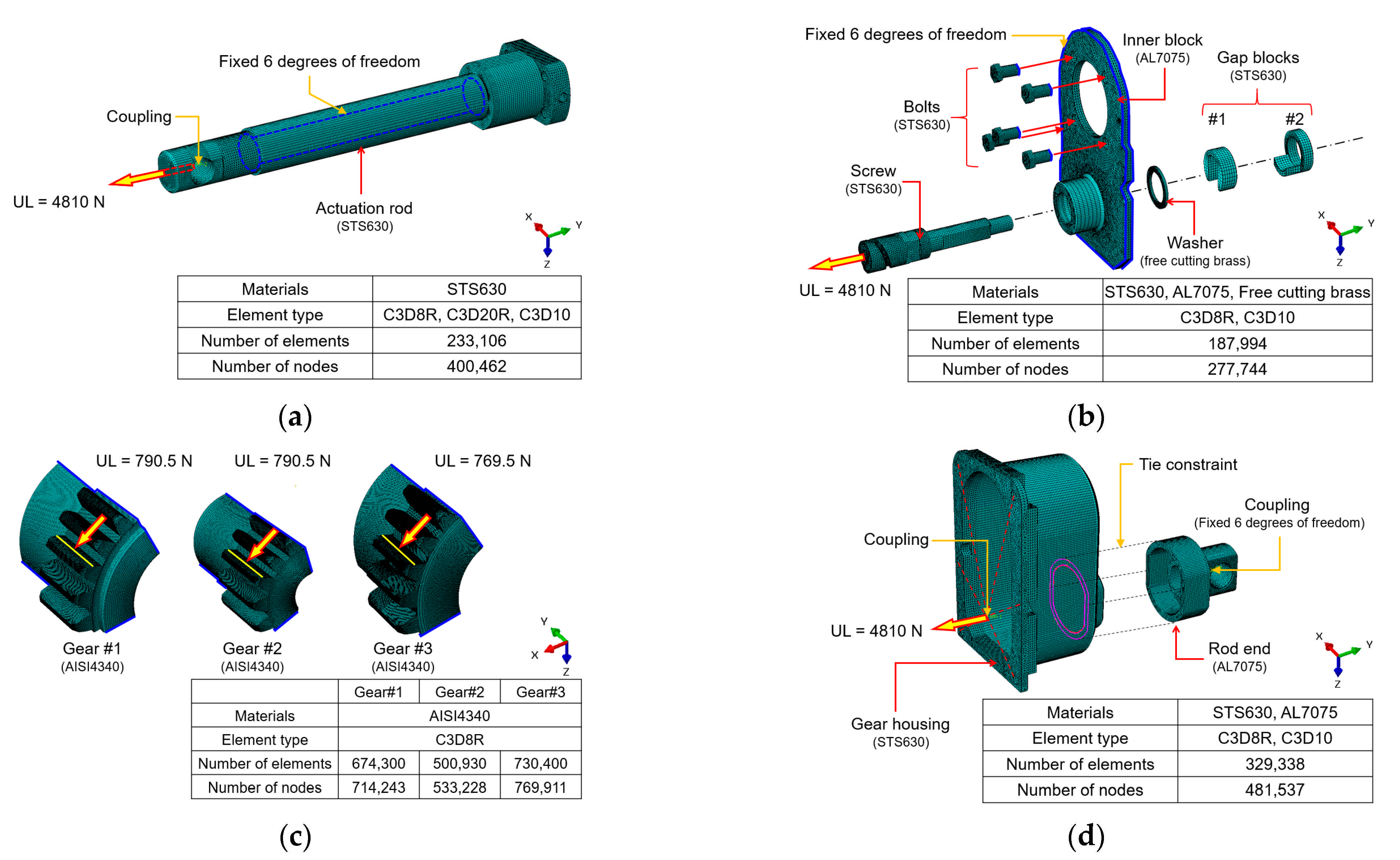
3.2. Static Analysis

Figure 4 shows the finite element models of the linear actuator components used in the structural analysis. For the actuation rod shown in Figure 4a, a key component that transmits force, high structural strength is required for the joint connected to the shaft. In this instance, the axial reaction force of the actuation rod under the UL condition obtained from MBD analysis was applied to the joint of the actuation rod, and the inside of the actuation rod in contact with the screw was constrained by six degrees of freedom (DOFs). In addition, hexahedral (C3D8R, C3D20R) and tetrahedral (C3D10) elements were applied depending on the geometry of each component.
Figure 4b shows the calculation model of the inner block assembly. The inner block is a key component that constrains the translational movement of the screw in the axial direction. The inner block consists of a screw, a washer, two gap blocks for fixing the screw to the inner block, and bolts for fixing the inner block to the gear housing. In this study, the screw shaft was replaced with a purchased product, and D-cut machining was performed in the rear part of the shaft for the application of gap blocks.
Therefore, for the screw, structural analysis was conducted only on the rear part. The axial reaction force of the actuation rod was applied to the front part of the screw shaft and the 6-DOFs constraint was applied to the bolts and inner block edge. Hexahedral (C3D8R) and tetrahedral (C3D10) elements were applied depending on the geometry of each component.
For the gear train, structural analysis was conducted under bending load to evaluate the structural strength of the root of tooth of each gear [21]. In this instance, structural analysis was conducted by reducing the model with all gear teeth to a model with five gear teeth to shorten the analysis time as shown in Figure 4c. Previously, the static analysis results of the model with all gear teeth (Gear#1) were compared with those of the model with a reduced number of gear teeth. It was found that the models exhibited the maximum principal stress values of 108.0 and 108.1 MPa at the root of tooth, respectively, resulting in an error of 0.1%. This indicates that structural analysis of the model with a reduced number of gear teeth is reasonable. Meanwhile, the maximum contact force applied between the gears was estimated from MBD analysis, and the load position was selected using the ISO 6336-3 standard as shown in Figure 4c [22,23]. In addition, a 6-DOF constraint was applied to the cut surface of the gear teeth along with the application of the hexahedral (C3D8R) element.
Figure 4d shows the finite element model of the housing cover. It consists of a gear housing that surrounds the gear train and a rod end that fixes the linear actuator to a jig. For the contact surface between the rod end and the gear housing, the tie constraint was used. A reference point (RP) was designated in the space where the screw shaft was located, and the area fastened with bolts was constrained to RP through the coupling constraint. The axial reaction force of the actuation rod was then applied to RP. As for elements, a combination of the C3D8R and C3D10 elements was applied. Static analysis was conducted using ABAQUS/standard (version 2019, Dassault Systemes, Vélizy-Villacoublay, France), a commercial finite element software program.

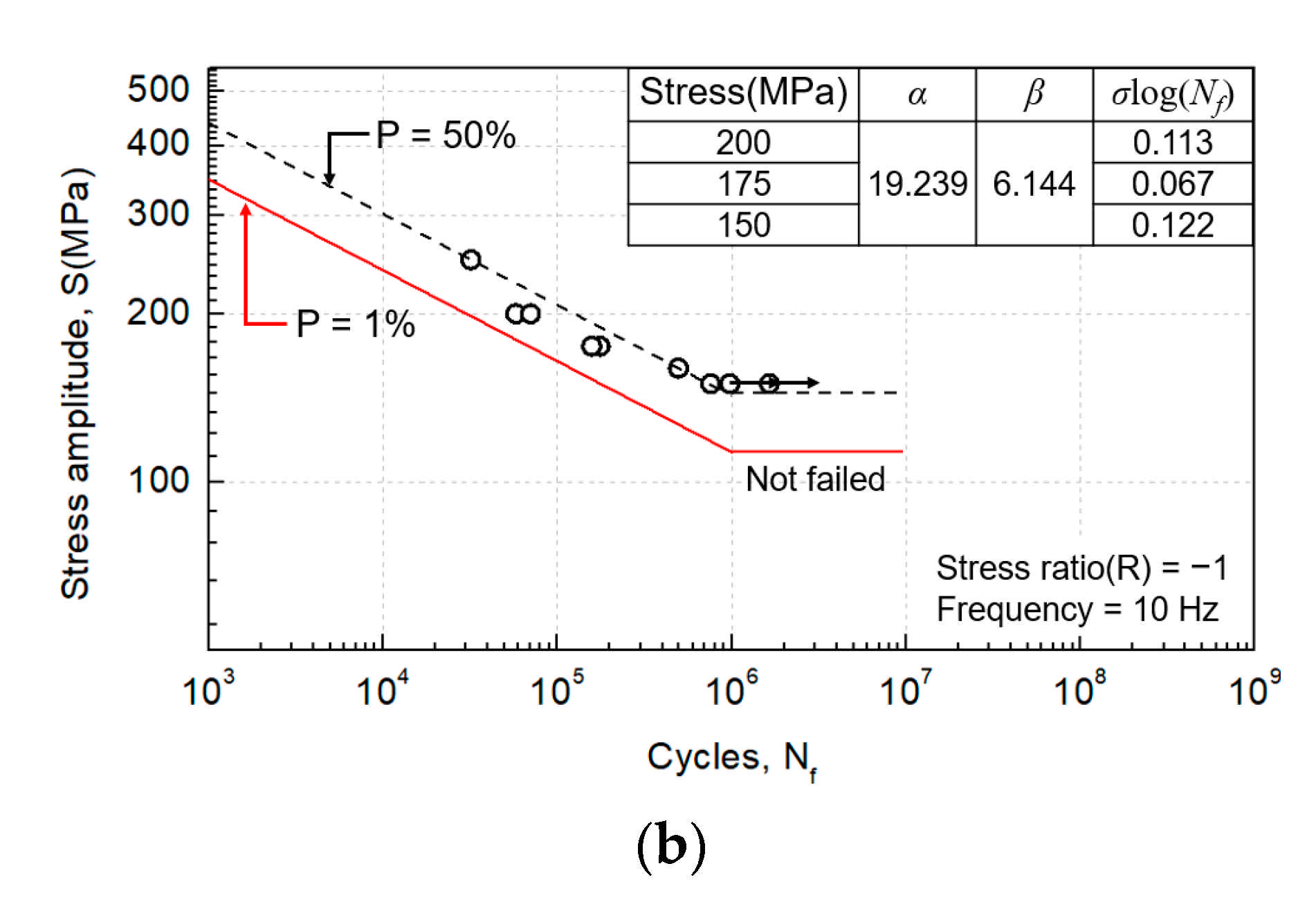
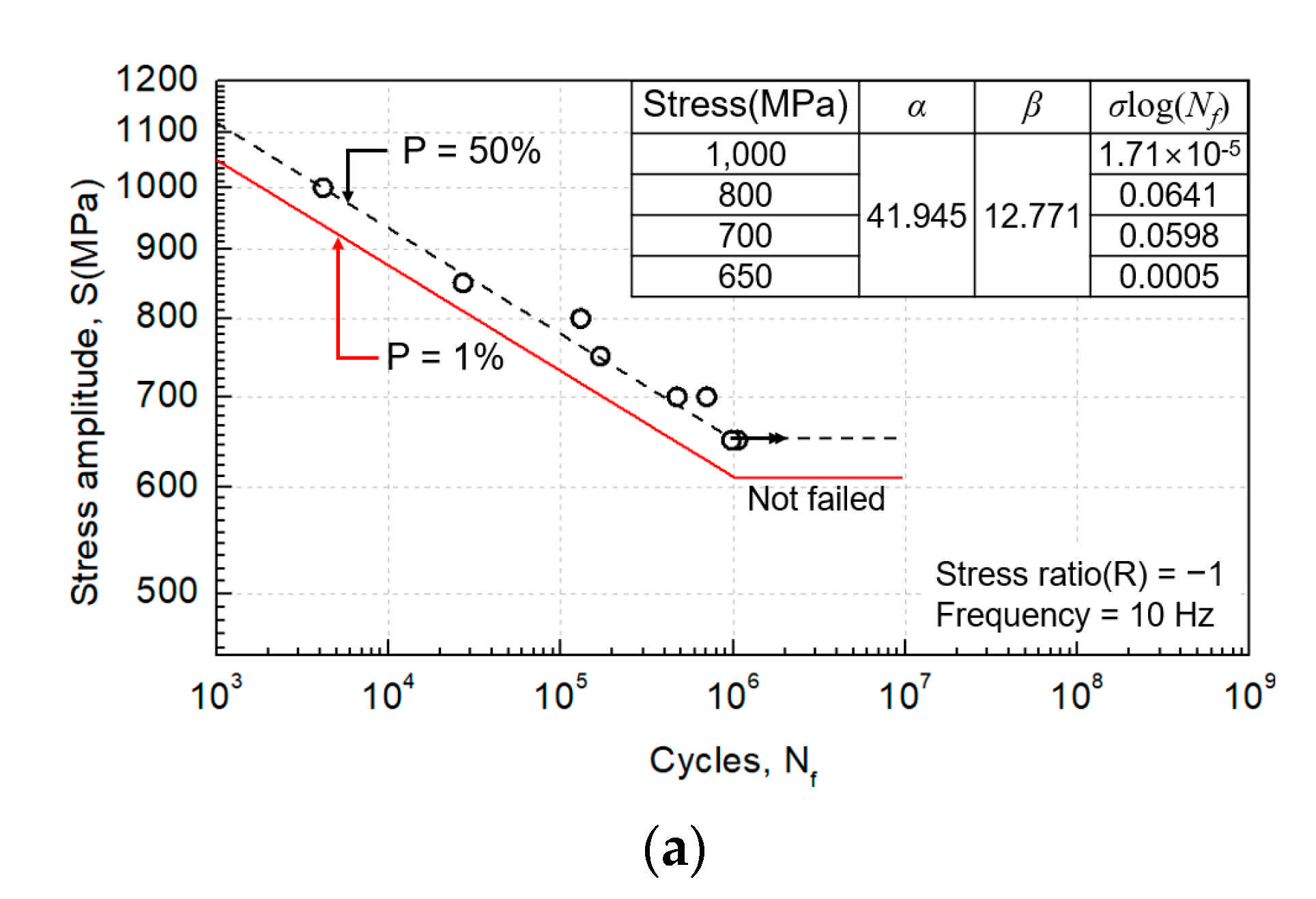
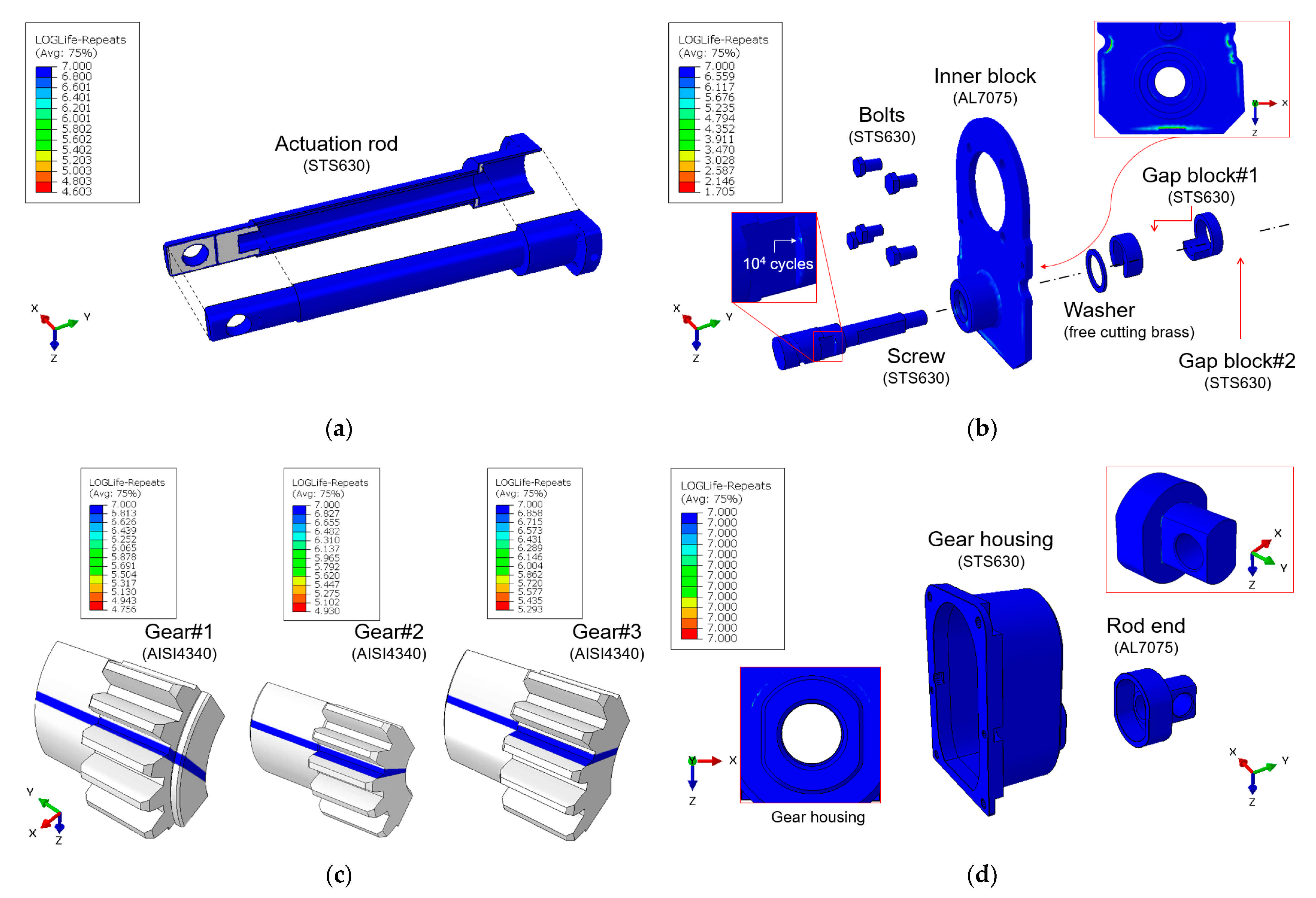
3.3. Fatigue Analysis

In this study, the stress data calculated by the static analysis in ABAQUS were used for fatigue analysis. Accordingly, the static analysis was additionally conducted, and the load (3680 N) obtained by multiplying the axial reaction force (3210 N) of the actuation rod by a factor of 1.15 was applied (KAS Part 23.572) [24]. The stress history used in fatigue analysis was then derived from the calculated stress distribution and the operating profile of the linear actuator shown in Figure 2. The P-S-N and S-N curves of each material obtained from the fatigue tests and literature survey were used, and the stress-life approach suitable for high-cycle fatigue analysis was applied [25]. As for the fatigue analysis of the gear teeth, the fatigue multiplying factor ( K f ) was considered [21]. K f can improve the accuracy of analysis by considering various factors, such as the surface characteristics, gear tooth size, load, and temperature. K f is calculated using Equation (3).
K f = K a × K b × K c × K d
where K a and K b are the surface and gear size factors. K c and K d are the load and temperature factors. In the case of the gear tooth subjected to a bending load, K c of 1 was adopted. Furthermore, K c of 1 was applied considering room temperature conditions for the actual durability tests of the actuator. The surface factor K a is calculated through Equation (4).
K a = a × S u t b
where the values of constants a and b are 4.45 and −0.265, respectively. The ultimate strength of AISI4340 (781 MPa) was applied to the ultimate strength S u t . The size factor K b of the gear with a rectangular cross-section is calculated through Equations (5) and (6) [26].
d e = 0.808 w t
K b = 1.24 × d e 0.107
where w , t , and d e are the gear tooth width, gear tooth thickness, and effective diameter of the gear which are listed in Table 3.
K f used for gear tooth fatigue analysis was calculated; the calculated factors are listed in Table 4.
FE-safe, a commercial FE-based fatigue analysis software program, was used. Additionally, more than 106 cycles, which is the required durability life of the linear actuator, was considered to be infinite life.

4. Results

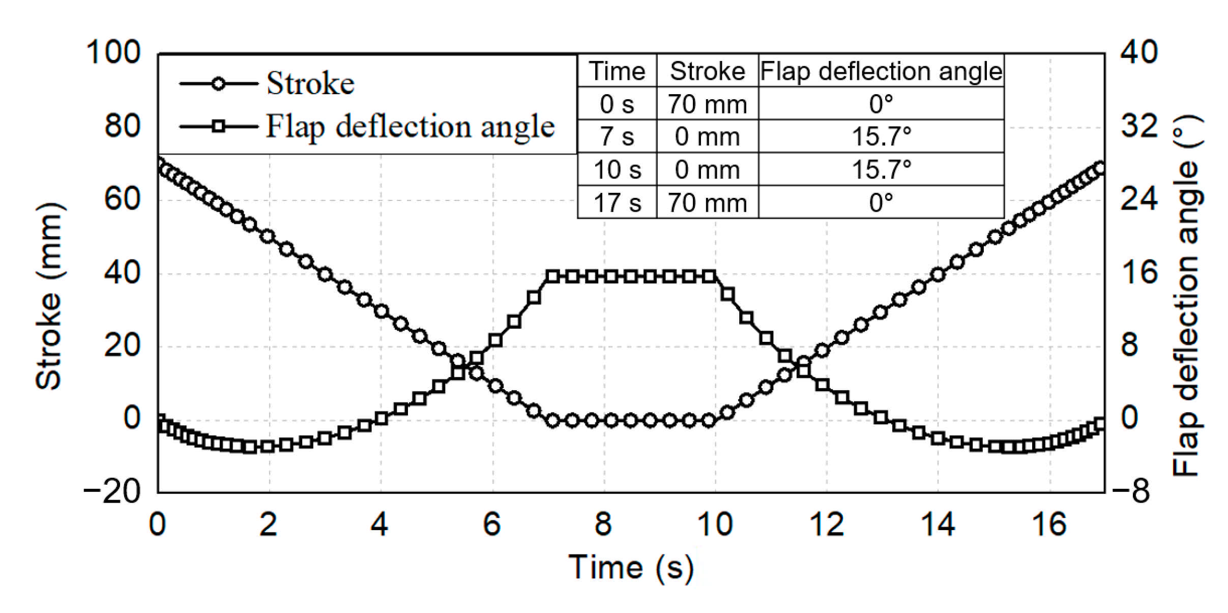
4.1. Multibody Dynamics Analysis

Figure 5 shows the maximum flap deflection angle derived through MBD analysis.
The flap deflection angle increased as the stroke of the linear actuator decreased and the maximum deflection angle of 15.67° was observed at seven seconds. Furthermore, the load simulator moved up to 48.72 mm and applied the maximum axial load to the linear actuator. Figure 6 shows the axial reaction force of the linear actuator under the UL condition. As the stroke of the linear actuator decreased, the load simulator moved, and a reaction force was applied to the linear actuator due to the elastic force of the coil spring. Concurrently, the maximum load of approximately 4810 N was calculated between seven and ten seconds. The calculated maximum load was found to be close to the UL (4800 N) mentioned in Section 2 and it was applied to static analysis of the detailed parts of the linear actuator.
Figure 7 shows the contact forces between the gear teeth under the UL condition.
The overall tendencies of the contact forces over time were similar to the axial reaction force of the linear actuator presented in Figure 6. When the force curves between 4 and 4.5 s were magnified for precise analysis, regular forces similar to a sine wave were observed as shown in Figure 7. The reason may be the engagement of the gear teeth with each other and their subsequent rotation. Meanwhile, the maximum contact forces for the loading points, shown in Figure 4c, were estimated to obtain the load to be applied to the static analysis of the gear teeth. It was found that the maximum contact forces occurred at 6.96 s and the values are presented in Table 5.
The reaction force and contact force of each component were derived under the operating conditions of the linear actuator, and they were applied to finite element based structural analysis.

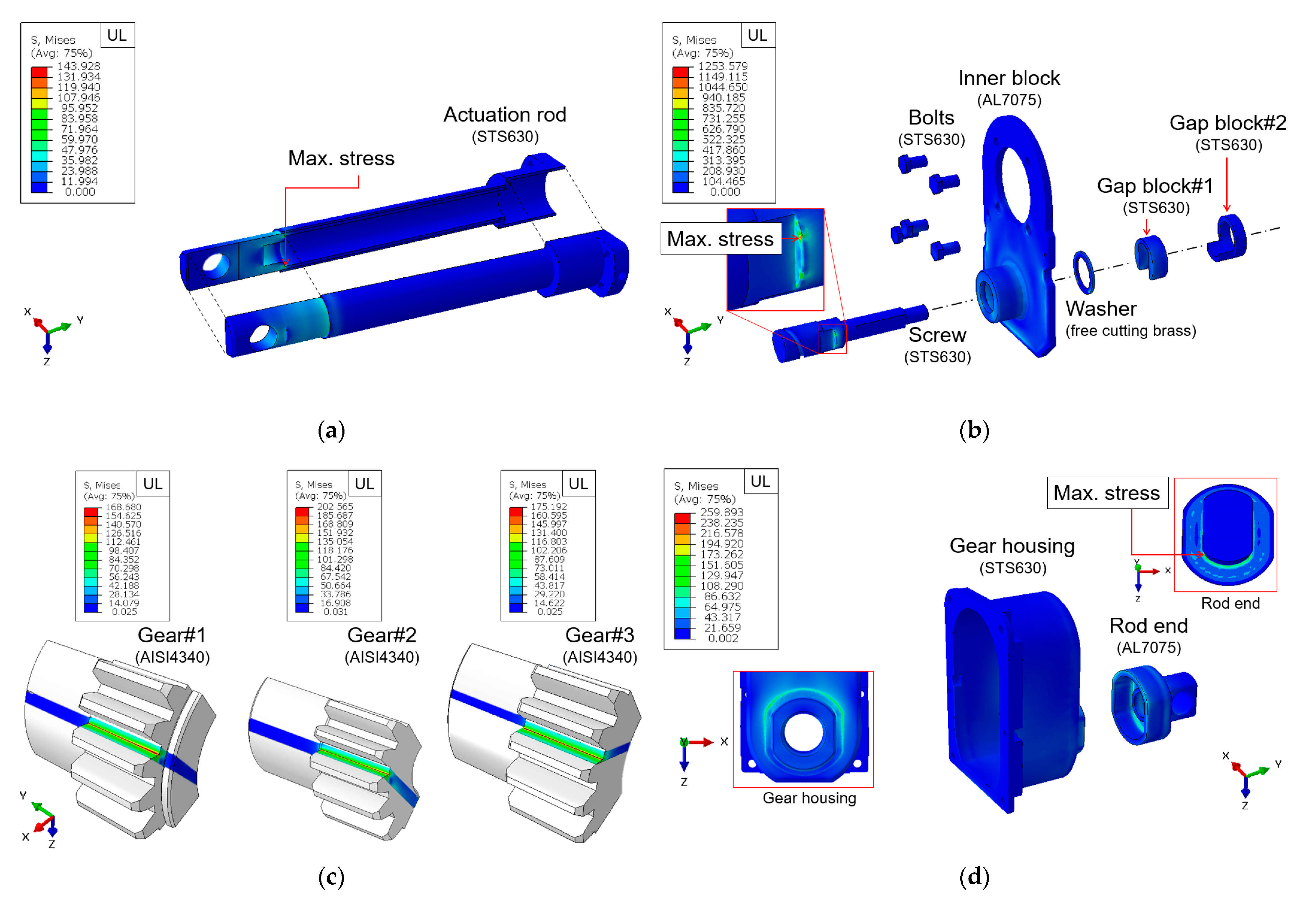
4.2. Static Analysis

Figure 8 shows the von Mises stress distribution under the UL condition derived from the static analysis. KAS Part 23.305 specifies that a structure should be able to support DLL without any harmful permanent deformation (yielding) [9]. Therefore, in this study, structural safety was evaluated by calculating the MoS based on the von Mises stress under the UL condition, which considered DLL, a safety factor, and the mechanical properties (yield strength) of the materials. MoS was calculated using Equation (7).
MoS = S y σ v 1
where S y is the yield strength of the material and σ v is the von Mises stress for UL. If the value of MoS is smaller than zero (MoS < 0), the design needs to be improved because structural design requirements are not satisfied.
In the case of the actuation rod, the maximum von Mises stress under the UL condition was calculated to be 143.9 MPa as shown in Figure 8a, which occurred in an area where geometry dramatically changed inside the actuation rod. Additionally, the calculated maximum von Mises stress was approximately 12.8% of the yield strength of STS630, which is the material of the actuation rod, therefore resulting in an MoS value of 6.7. Although the actuation rod is structurally safe under the UL condition, it is overdesigned and some design improvements for weight reduction are required.
In the case of the inner block assembly, the maximum von Mises stress was found in the area of the screw where D-cut machining was applied as shown in Figure 8b. This is because stress concentration occurred due to the contact with gap block #1. A high von Mises stress value of 1254 MPa was calculated under the UL condition, and an MoS value of −0.1 was calculated using the yield strength of the screw material (STS630). This indicates that design improvements are required for the screw by changing its geometry and material because it can be subjected to permanent deformation or damage out of the elastic region under the UL condition. For the inner block and washer, the maximum von Mises stress values under the UL condition were found to be 524.7 and 288.0 MPa, respectively and the maximum stress occurred in the area where the inner block and washer were in contact with each other. The corresponding MoS values were calculated to be 0.0 and 0.1, respectively. For the other components (bolts and gap blocks #1 and #2), MoS was calculated to be 4.1 or higher, confirming that they were structurally safe.
Figure 8c shows the von Mises stress distribution of the roots of tooth of each gear calculated through the static analysis. The maximum von Mises stress values of the roots of tooth for gears #1–3 under the UL condition were calculated to be 168.7, 202.6, and 175.2 MPa, respectively. Additionally, the MoS values were found to be 2.4, 1.8, and 2.3, confirming that all the gears in the gear train were structurally safe against bending loads.
In the case of the housing cover, the maximum von Mises stress occurred in the area where the geometry of the rod end dramatically changed as shown in Figure 8d. In this instance, the maximum stress of 259.9 MPa was derived under the UL condition, and an MoS value of 1.0 was calculated. As for the gear housing, the maximum von Mises stress of 137.5 MPa occurred in the part in contact with the rod end under the UL condition and an MS value of 7.1 was calculated, confirming that it was overdesigned despite its structural safety. Therefore, design improvements for weight reduction are required for the gear housing which represents a high proportion in the total weight of the linear actuator.

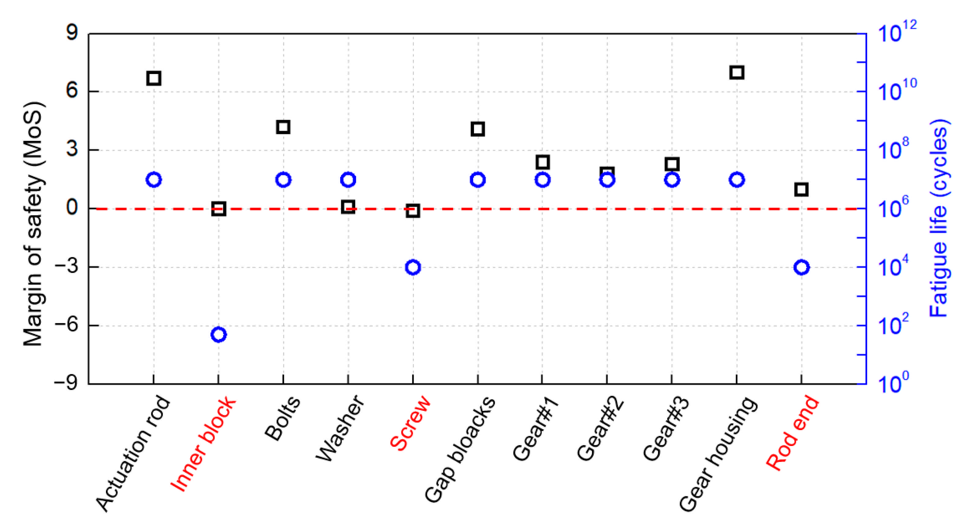
4.3. Fatigue Analysis

Figure 9 shows the fatigue life distribution each component of the linear actuator calculated through fatigue analysis.
In the actuation rod, the fatigue life of 106 cycles or more was satisfied in all areas as shown in Figure 9a. This confirmed that the actuation rod is structurally safe against repeated loads under the operating conditions of the linear actuator. As for the inner block assembly, the fatigue life of 106 cycles or more was calculated for the bolts, washer, and gap blocks #1 and #2 as shown in Figure 9b. In the case of the screw area with D-cut machining, which was selected as a vulnerable area in Section 4.2, however, a relatively low fatigue life of approximately 104 cycles was observed. In addition, a very low fatigue life of approximately 50 cycles was derived in the inner block in contact with the gear housing. Although the fatigue strength of the AL7075 material calculated through the P-S-N curve was set excessively low, it is clear that the area is vulnerable to stress concentration. Therefore, it was confirmed that the inner block and screw are structurally vulnerable because they could not satisfy the required life under repeated loads and design improvement is required to prevent stress concentration.
Figure 9c shows the bending fatigue analysis results for the gear teeth. 14 times of revolutions were required for the gears per one reciprocating operation according to the operating profile shown in Figure 2. Therefore, 14 × 106 cycles, which was obtained by multiplying the required life of the linear actuator (106 cycles) by 14, were set as the required life. Nevertheless, all the gears satisfied the fatigue life for the area of root of tooth as shown in Figure 9c. This confirmed that all the gears of the linear actuator are structurally safe against repeated loads. Figure 9d shows the fatigue analysis results for the housing cover. The fatigue life of the gear housing was calculated to be more than 106 cycles, thereby satisfying the required durability life. However, for the rod end, fatigue life of approximately 104 cycles was calculated in the area where the geometry dramatically changed. Therefore, the gear housing is structurally safe against repeated loads under the operating conditions of the linear actuator; although, the rod end requires design improvements to prevent stress concentration because it could not satisfy the required life.
Structural safety under the UL and repeated load conditions were evaluated for all the key components of the linear actuator. Figure 10 shows the MoS and fatigue life of each component calculated through the static and fatigue analysis. As shown in Figure 10, most of the components of the linear actuator were found to be structurally safe against UL and repeated loads (MoS ≥ 0). The inner block and the rod end of the housing cover, however, could not satisfy the required life against repeated loads even though they were structurally safe under the UL condition. Additionally, the screw requires design improvement because it was found to be structurally vulnerable to both the UL and repeated load conditions.

5. Conclusions

Essential problems that arise during the certification of aircraft are economic elements (e.g., cost and time) and safety. Aircraft manufacturers and operators aim to minimize development and maintenance costs, whereas airworthiness authorities demand the highest safety [27]. Therefore, many studies have been conducted on certification for aircraft design and manufacturing to reduce the cost and time required for development and secure structural safety by introducing analytical methods. As a result of recent advances in analysis technology, regulations that require structural safety to be verified through a combination of analysis and tests have been consistently prepared in the Korean airworthiness standards (KAS) (KAS Part 23.305 and KAS Part 23.307). In this study, the structural safety of aircraft components was evaluated using finite element analysis (FEA) and techniques for verifying structural safety through analytical methods were proposed according to the airworthiness standards.
As part of this study, static structural and fatigue safety were evaluated for the linear actuator for flap control of small aircraft. First, a test rig for the linear actuator was modeled and a multibody dynamics (MBD) analysis was conducted to calculate the force data for using in structural analysis. Based on the calculated forces (reaction force and contact force), the FE-based static analysis was conducted, and static structural safety was evaluated by deriving the margin of safety (MoS). Additionally, fatigue safety was evaluated by conducting the FEA based on the stress data calculated by the static analysis and the operating profile of the linear actuator. It was found that the area of the screw where D-cut machining was applied is vulnerable in terms of static structural and fatigue safety because of the high stress concentration. In addition, high stress occurred in the inner block in contact with the gear housing and the rod end exhibited high stress in the area where the geometry dramatically changed. Although static structural safety was obtained, fatigue safety was found to be vulnerable. Therefore, the geometry should be modified to reduce the stress concentration by applying the fillets to the corner whose shape changes abruptly, or the material with higher strength needs to be adopted to the structurally vulnerable components to improve their MoS.
As described, the possibility of evaluating the structural safety of aircraft components through analytical methods was confirmed in this study. The proposed structural analysis techniques can be used in evaluation of the structural safety of civil aircraft and will contribute to reducing the costs of certification process. Moreover, we expected that the actual static and fatigue tests will be conducted to verify the analytical results presented in this study, and then their substitutability by the analytical simulation will be confirmed to evaluate the structural safety of linear actuator in the future.

Author Contributions

Conceptualization, D.-H.K. and S.-W.K.; methodology, D.-H.K.; validation, D.-H.K.; formal analysis, D.-H.K. and Y.-C.K.; investigation, Y.-C.K.; data curation, Y.-C.K.; writing—original draft preparation, D.-H.K.; writing—review and editing, S.-W.K.; visualization, D.-H.K.; supervision, S.-W.K.; project administration, S.-W.K.; funding acquisition, S.-W.K. All authors have read and agreed to the published version of the manuscript.

Funding

This study was funded by the aerospace component technology development project supervised by the Ministry of Trade, Industry and Energy and by the National Research Foundation of Korea (NRF) grant funded by the Korea government (MSIT).

Institutional Review Board Statement

Not applicable.

Informed Consent Statement

Not applicable.

Data Availability Statement

Not applicable.

Acknowledgments

This study was supported by the aerospace component technology development project supervised by the Ministry of Trade, Industry and Energy (No. 20003475) and by the National Research Foundation of Korea (NRF) grant funded by the Korea government (MSIT) (NO. 2019R1A2C4070280). The authors are also grateful for the technical support of JNS Co., Ltd. and KM-Eng Co., Ltd.

Conflicts of Interest

The authors declare no conflict of interest.

References

  1. Song, Y.; Oh, S. Reliability analysis of aircraft flap. In Proceedings of the Spring Conference of The Korean Society of Mechanical Engineering, Suwon-si, Korea, 4–5 January 1994. [Google Scholar]
  2. Reports A-032/2008. Accident Involving a McDonnell Douglas DC-9-82 (Aircraft), Registration EC-HFP, Operated by Spanair, at Madrid-Barajas Airport; CIAIAC: Madrid, Spain, 2008. [Google Scholar]
  3. Aircraft Accident Report. Final Report Mandala PK-Rim 5Sep05; National Transportation Safety Committee: Jakarta, Indonesia, 2009. [Google Scholar]
  4. Ministry of Land, Infrastructure and Transport. KAS Part 23.697: Wing Flap Controls and Part 23.701: Flap Interconnection. 2013. Available online: http://atis.casa.go.kr/ACS/sub04_3.asp (accessed on 7 March 2021).
  5. Claeyssen, F.; Janker, P.; LeLetty, R.; Sosniki, O.; Pages, A.; Magnac, G.; Christmann, M.; Dodds, G. New actuators for aircraft, space and military applications. In Proceedings of the 12th International Conference on New Actuators, Bremen, Germany, 14–16 June 2010. [Google Scholar]
  6. Yoon, G.; Park, H.; Jang, K. The state of the art and application of actuator in aerospace. J. Korean Soc. Propuls. Eng. 2010, 14, 89–102. [Google Scholar]
  7. Hur, J. Study on fatigue life estimation for aircraft engine support structure. Trans. Korean Soc. Mech. Eng. A 2010, 34, 1667–1674. [Google Scholar] [CrossRef]
  8. Kim, S.; Kim, T. Study on aircraft fatigue life substantiation method. J. Korean Soc. Aeronaut. Space Sci. 2016, 24, 41–46. [Google Scholar]
  9. Ministry of Land, Infrastructure and Transport. KAS Part 23.305: Strength and Deformation and Part 23.307: Proof of Structure. 2013. Available online: http://atis.casa.go.kr/ACS/sub04_3.asp (accessed on 7 March 2021).
  10. Ministry of Land, Infrastructure and Transport. Notice 932: Procedures for Type Certification. 2017. Available online: https://www.molit.go.kr/USR/I0204/m_45/lst.jsp?gubun=1 (accessed on 7 March 2021).
  11. Kim, D.; Kim, M.; Kim, S. Evaluation of structural safety of critical design model of linear actuator for flap control of aircraft and test rig. Trans. Korean Soc. Mech. Eng. A 2020, 44, 733–744. [Google Scholar] [CrossRef]
  12. Kim, D.; Kim, S. Evaluation of structural safety of linear actuator for flap control of aircraft. J. Aerosp. Syst. Eng. 2019, 13, 66–73. [Google Scholar]
  13. Ministry of Land, Infrastructure and Transport. KAS Part 23.301: Loads and Part 23.303: Factor of Safety. 2013. Available online: http://atis.casa.go.kr/ACS/sub04_3.asp (accessed on 7 March 2021).
  14. Cho, H.; Lee, I.; Kim, S.; Park, S.; Yang, M. No-failure accelerated life test of flap actuating system using Weibull distribution. J. Aerosp. Syst. Eng. 2016, 10, 51–58. [Google Scholar] [CrossRef]
  15. SAE-AISI 4340 (SNCM439, G43400) Ni-Cr-Mo Steel. Available online: https://www.makeitfrom.com/material-properties/SAE-AISI-4340-SNCM439-G43400-Ni-Cr-Mo-Steel (accessed on 7 March 2021).
  16. Free Cutting Brass UNS C36000. Available online: https://www.azom.com/article.aspx?ArticleID=6391 (accessed on 7 March 2021).
  17. ASTM. ASTM E8/E8M-16a Standard Test Methods for Tension Testing of Metallic Materials. 2016. Available online: https://www.astm.org/DATABASE.CART/HISTORICAL/E8E8M-16A.htm (accessed on 7 March 2021).
  18. ASTM. ASTM B557-15 Standard Test Methods for Tension Testing Wrought and Cast Aluminum-and Magnesium-Alloy Products. 2015. Available online: https://www.astm.org/Standards/B557.htm (accessed on 7 March 2021).
  19. ASTM. ASTM E466-15 Standard Practice for Conducting Force Controlled Constant Amplitude Axial Fatigue Tests of Metallic Materials. 2015. Available online: https://www.astm.org/Standards/E466 (accessed on 7 March 2021).
  20. JSME S002. Standard method of statistical fatigue testing. J. Jpn. Soc. Mech. Eng. 1994, 10–42. [Google Scholar]
  21. Kim, T.; Lee, J.; Hur, S.; Seol, J.; Lee, B. A study on the finite element fatigue analysis of single tooth of reduction gear of aircraft. In Proceedings of the Society for Aerospace System Engineering Fall Conference, Gyeongju-si, Korea, 31 October–2 November 2018. [Google Scholar]
  22. ISO 6336-3. Calculation of Load Capacity of Spur and Helical Gears—Part 3: Calculation of Tooth Bending Strength, 2nd ed.; ISO: Geneva, Switherland, 2019. [Google Scholar]
  23. Kim, D.; Kim, G.; Kim, J.; Ahn, B. Fatigue test and analysis of automotive bevel gear. In Proceedings of the Spring Conference of the Korea Society of Mechanical Engineers, Busan, Korea, 26–27 May 2005. [Google Scholar]
  24. Ministry of Land, Infrastructure and Transport. KAS Part 23.572: Metallic Wing, Empennage, and Associated Structures. 2013. Available online: http://atis.casa.go.kr/ACS/sub04_3.asp (accessed on 7 March 2021).
  25. Park, Y.; Im, J.; Park, J. Damage tolerant design for the tilt rotor UAV. J. Aerosp. Syst. Eng. 2007, 1, 27–36. [Google Scholar]
  26. Budynas, R.; Nisbett, J. Shigley’s Mechanical Engineering Design, 9th ed.; McGraw-Hill Book Company: Newyork, NY, USA, 2012. [Google Scholar]
  27. Kim, S.; Kim, T. Study on fixed wing aircraft fatigue life substantiation method. In Proceedings of the Fall Conference of the Korean Society for Aeronautical and Space Sciences, Jeju-si, Korea, 18–20 November 2015. [Google Scholar]
Figure 1. (a) The test rig and (b) the linear actuator models.
Aerospace 08 00104 g001
Figure 2. The operating profile of the linear actuator.
Aerospace 08 00104 g002
Figure 3. (a) The P-S-N curve of the STS630-H1025 and (b) the AL7075-T651 materials.
Aerospace 08 00104 g003aAerospace 08 00104 g003b
Figure 4. The calculation models of a linear actuator, loads, and the boundary conditions used in structural analysis. (a) Actuation rod; (b) Inner block assembly; (c) Gear train; (d) Housing cover.
Aerospace 08 00104 g004
Figure 5. The maximum flap deflection angle at (a) 0 s and (b) 7 s.
Aerospace 08 00104 g005
Figure 6. The reaction forces of the actuation rod over time.
Aerospace 08 00104 g006
Figure 7. The contact forces of the gear teeth over time.
Aerospace 08 00104 g007
Figure 8. The von Mises stress distribution of the components of the linear actuator obtained from the static analysis. (a) Actuation rod; (b) Inner block assembly; (c) Gear train; (d) Housing cover.
Aerospace 08 00104 g008
Figure 9. The fatigue life (logarithmic scale) of the components of the linear actuator obtained from the fatigue analysis. (a) Actuation rod; (b) Inner block assembly; (c) Gear train; (d) Housing cover.
Aerospace 08 00104 g009
Figure 10. Margin of safety and fatigue life for components of linear actuator.
Aerospace 08 00104 g010
Table 1. The requirement specifications of the linear actuator.
SpecificationsValuesUnits
Load rating3200N
Maximum velocity10mm/s
Maximum stroke70mm
Life cycles1,000,000cycles
Table 2. The mechanical properties used in the structural analysis.
PropertiesMaterialsUnits
STS630-H1025AL7075-T651Free-Cutting BrassAISI4340
Young’s modulus200.472.097.0205.0GPa
Poisson’s ratio0.280.330.330.28mm/mm
Yield strength1122.0536.5310.0586.0MPa
Ultimate strength1134.6577.5469.0781.0MPa
Fatigue strength
( N f = 106 cycles)
610.9113.1138.0387.6MPa
Table 3. The dimensions of the gear teeth used to calculate the size factor ( K b ).
ComponentsThicknessesWidthsEffective Diameters
Gear#11.50 mm8 mm24 mm
Gear#21.47 mm8 mm17 mm
Gear#31.50 mm8 mm24 mm
Table 4. The various factors used in the calculation of the fatigue multiplying factor ( K f ).
Components K a K b K c K d K f
Gear#10.7621.11110.85
Gear#20.7621.14110.87
Gear#30.7621.11110.85
Table 5. The maximum contact forces of the gear teeth used in the structural analysis.
ComponentsULUnits
Gear#1–2790.5N
Gear#2–3769.5N
Publisher’s Note: MDPI stays neutral with regard to jurisdictional claims in published maps and institutional affiliations.

