Article

Recent Advances of the BIRALET System about Space Debris Detection

1
National Institute for Astrophysics (INAF), Cagliari Astronomical Observatory, Via della Scienza 5, 09047 Selargius, Italy
2
Department of Electrical and Electronic Engineering, University of Cagliari, Piazza D’Armi snc, 09123 Cagliari, Italy
3
Italian Space Agency, Via del Politecnico, 09133 Rome, Italy
*
Author to whom correspondence should be addressed.
Aerospace 2021, 8(3), 86; https://doi.org/10.3390/aerospace8030086
Submission received: 3 February 2021 / Revised: 13 March 2021 / Accepted: 17 March 2021 / Published: 19 March 2021
(This article belongs to the Special Issue New Space: Advances in Space Science and Engineering)

Abstract

:
Space debris is internationally recognized as a planetary threat. Efforts to enhance the worldwide radar monitoring networks have been intensified in the last years. Among the new radars employed for the observations, one of the most promising is the Bistatic Radar for Low Earth Orbit (LEO) Tracking (BIRALET), which employs the Sardinia Radio Telescope as a receiving segment. The Sardinia Radio Telescope (SRT) has recently been proven to be a reliable instrument for space debris monitoring and, for this purpose, over the years has undergone some substantial modifications in order to be able to rise to the status of a fully functional radar receiver. However, an extensive measurement campaign, in order to assess the real potential of the radar, has never been done before. In this paper, the authors present the first real space debris measurement campaign of the SRT, made between December 2018 and October 2019 using the new dedicated channel of the P-band receiver. A total of 27 objects were correctly detected during this campaign, characterized by a radar cross section (RCS) interval between 0.13 and 13.4 m2 and a range interval between 459 and 1224 km.

1. Introduction

Based on recent estimates, the number of orbital debris in space amounts to 139 million [1]. The overpopulation of objects within the space environment increases the chance of several events that could lead to catastrophic consequences, such as collisions, fragmentations, and reentries in the Earth’s atmosphere [2,3]. Such a risk forced worldwide space agencies to develop a set of countermeasures to prevent and/or mitigate possible threats. The latter take the form of the space situational awareness (SSA) program and, more specifically, of one of its constituent segments: the space surveillance and tracking (SST), which focuses on the active and inactive objects that orbit the earth [4]. The embodiment of this planetary commitment can be figured out paying attention to the size of the huge network of sensors dedicated to space monitoring [5,6,7]. Despite the undeniable supremacy of the United States, the necessity of an organized SST segment is also prioritized by other countries [7].
Within this framework, recently, Italy has also been involved in the European monitoring program for SST. The two main radar systems for space debris monitoring in Italy are the BIRALES (Bistatic Radar for Low Earth Orbit Survey) [8] and the BIRALET (Bistatic Radar for Low Earth Orbit Tracking) [9] (refer to the Supplementary Materials). These bistatic radars share the same transmitter, but, for the first system, the receiver is the Northern Cross, located in Medicina, near Bologna (Northern Italy), whereas for the second one, the receiver is the Sardinia Radio Telescope (SRT), located near Cagliari (Sardinia, South-West Italy) [9,10]. Starting from early 2014 [11], the SRT has been involved in the Italian and European space debris monitoring program and it has been gradually upgraded to make it more suitable for space debris observations [12]. As pointed out in both [11,13], the first measurements performed in April 2014 were planned to assess the potential of the SRT as a receiver in a bistatic radar system for space debris monitoring. On that occasion, the observation schedule included a total of six pieces of debris, each one correctly spotted [11]. However, these first results, although encouraging, showed the shortcomings of the employed system, tied also to the inadequacy of the back-end (e.g., speed of the frequency sweep tied to the resolution bandwidth selected, poor processing capabilities, and missing information due to the sampling time), which was mainly used for the primary mission of the radiotelescope, i.e., radioastronomical observations [9,14].
Because of these limitations, in a recent paper, the authors presented the design and realization of a new space debris dedicated channel for the SRT [12,13]. The new channel is based on the introduction of a few filtering stages and a down-conversion section necessary to match the working frequency of the new back-end, based on the FPGA commercial board Red Pitaya (model STEMLab 125-14: https://www.redpitaya.com/f130/STEMlab-board, accessed on 19 March 2021). The channel has been tested taking advantage of the reentry of the Chinese space station Tiangong–1 on April 2018, in a joint operation with the BIRALES system, with the aim to retrieve the speed of the falling object from the Doppler measurements [13]. However, as the Tiangong-1 was characterized by an overall radar cross section (RCS) of about 20 m2, that measurement cannot be considered a real testing ground for the capabilities of the new system. Moreover, the observation of the Tiangong–1 was focused on the calculation of the speed from the Doppler frequency of the space station. Therefore, a further set of observations has been scheduled, including objects with a rather wide interval in terms of RCS and range. Accounting for objects with different RCS and range is pivotal for an extensive campaign to assess the capabilities of a radar system. Small and far objects can give a hint on the sensitivity of the system, whereas large and near objects are useful for the calibration of the receiving chain, as the blinding of the receiver must be avoided. Despite the great distance between radar and debris, the reflected signal could be high enough to saturate the amplification stage of the receiving chain.
In this paper, the most extensive space debris measurement campaign ever performed by the BIRALET system is presented. Previous measurement sessions reported too few detections to be considered a solid benchmark for future campaigns. The measurements discussed herein were taken in a kind of beam-parking mode: the objects were part of a predetermined list provided by the Italian Air Force. This compromise was necessary, as the transmitter is located in a military facility. Unfortunately, this also means that we had no control of the pool of observable objects. For every object in the list, the SRT was pointed at the right coordinates (predicted by means of two-line element sets—TLE [15]), waiting for the passage of the object inside the beam. During the campaign, performed between December 2018 and October 2019, a total of 27 objects were correctly detected, with a RCS variation in the range of 0.13–13.4 m2 and a slant range (SR—intended as the sum of the ranges of the object from the receiver and the transmitter) variation between 918 and 2077 km. The results show also that the estimated Doppler shift was predicted with a maximum error of about 1 kHz.

2. The BIRALET System

The BIRALET system is a bistatic radar configuration located in Sardinia (Italy). The transmitter of the BIRALET is the TRF (Trasmettitore a Radio Frequenza—Radio Frequncy Transmitter), a 7 m fully steerable wheel-and-track parabolic antenna with a primary focus configuration, located in the region “Salto di Quirra” (Northeast from Cagliari). The azimuth and elevation range of the transmitting antenna are 0–360 deg and 0–90 deg, respectively, with an accuracy of 0.1 deg and a speed of 3 deg/s in both directions [8]. The TRF is capable of transmitting a continuous wave (CW) signal of 10 kW at 410 MHz. The receiver of the BIRALET system is the SRT, a 64 m fully steerable wheel-and-track parabolic antenna (Figure 1) devoted mainly to radio astronomical observations, located in Pranu Sanguini (Northeast from Cagliari), operating in the frequency range from 0.3 to 116 GHz. In addition to the 64 m primary parabolic mirror, the antenna is equipped with a 7.9 m secondary mirror and the beam waveguide system (BWG), which includes two 2.9 m mirrors and one 3.9 m mirror, for a total of four focal positions [16,17,18,19,20]. To better clarify the mirrors and foci configuration of the SRT, a sketch of the antenna is reported in Figure 2, whereas Table 1 summarizes the key features of the radio telescope. One of the peculiarities of the SRT is the active surface system that allows the modification of the profile of the primary mirror (by means of an electro-mechanical control) in order to compensate for deformations tied to gravitational load, pressure of the wind, and thermal gradients [21].
The sensitivity of the bistatic system was computed in terms of scattered power from the targets, using the well-known radar equation [22] for the calculation of the received power and Equation (1) for the evaluation of the noise floor:
N F = k B T sys B N
where k B is the Boltzmann’s constant; T sys is the system temperature (as sum of the antenna and receiver temperature); and B N is the noise bandwidth, evaluated as the bandwidth of the output filter of the receiver. Figure 3 shows the simulated performances of the BIRALET system in terms of received power versus RCS for the range of values from 200 to 2000 km. The estimated signal-to-noise ratio (SNR) for a specific RCS can be derived easily by the difference between the received power and the noise floor. It is worth mentioning that the latter represents an ideal estimation of the SNR received, because, in a real measurement, the noise floor tends to be higher.
The receiver employed for the space debris observations is the P-band receiver, working between 305 and 410 MHz [13,23]. The receiver block is composed of five main sections: the coaxial feed, the cryogenic front-end, the linear to circular polarizer, the noise calibrator and antenna unit injection, and the filter selector. The radio frequency (RF) signal is received by the coaxial feed and sent to the cryogenic front end, directly connected to the noise calibration and antenna unit injection, for the calibration of the entire system. Then, the signal is sent to the polarizer, which allows the retrieval of the signal in both linear and circular polarizations. The last stage is the choice of a suitable filter depending on the type of measurement. More details on the P-band receiver can be found in [23]. The half-power beamwidth (HPBW) of the SRT in P-band (410 MHz) is about 0.8 deg, as shown in the radiation pattern reported in Figure 4.
The P-band receiver block is the first part of the space debris dedicated channel of the SRT. A complete schematic of the channel is reported in Figure 5. After the P-band receiver block, the signal goes in input to the focus selector, which allows the choice of the focus for the observation (the primary focus in our case). This section is characterized by a set of filters, amplifiers, and attenuators, providing an overall gain of about 20 dB. From the top of the parabolic reflector, the signal is then carried down to a shielded room at ground level, by means of a 500 m optical link. Inside the shielded room, downstream to the optical link, the signal passes through the IF distributor, which allocates the signals coming from the antenna to the different back-ends, and is characterized by an overall gain of about 20 dB.
The dedicated back-end for space debris observations is composed of the down-conversion block, and, finally, the Red Pitaya. The down-conversion block lowers the 410 MHz frequency of the incoming signal to match the working frequency of the back-end (0–50 MHz). The down-converted signal is filtered and amplified. A digital step attenuator, controlled by the Red Pitaya, is located upstream to the final amplifier in order to avoid saturation of the system. The setting of the digital attenuator is calibrated upon the power level of the carrier, as explained in [13]. The last block of the dedicated channel is the Red Pitaya, a commercial system-on-a-chip FPGA board provided with a dual-core 800 MHz ARM9 processor, a FPGA with 28,000 logic cells, 512 MB of DDR3 RAM system memory, 2 RF inputs and 2 RF outputs, an overall 3 dB-bandwidth of 50 MHz, a sample rate of 125 M Sample/s, and 14 bit of ADC resolution. A digital signal processing chain was built inside the board, allowing the conversion of the input signal in a base-band complex signal. This raw signal can be stored and post-processed using an FFT engine and, finally, displayed on a computer.

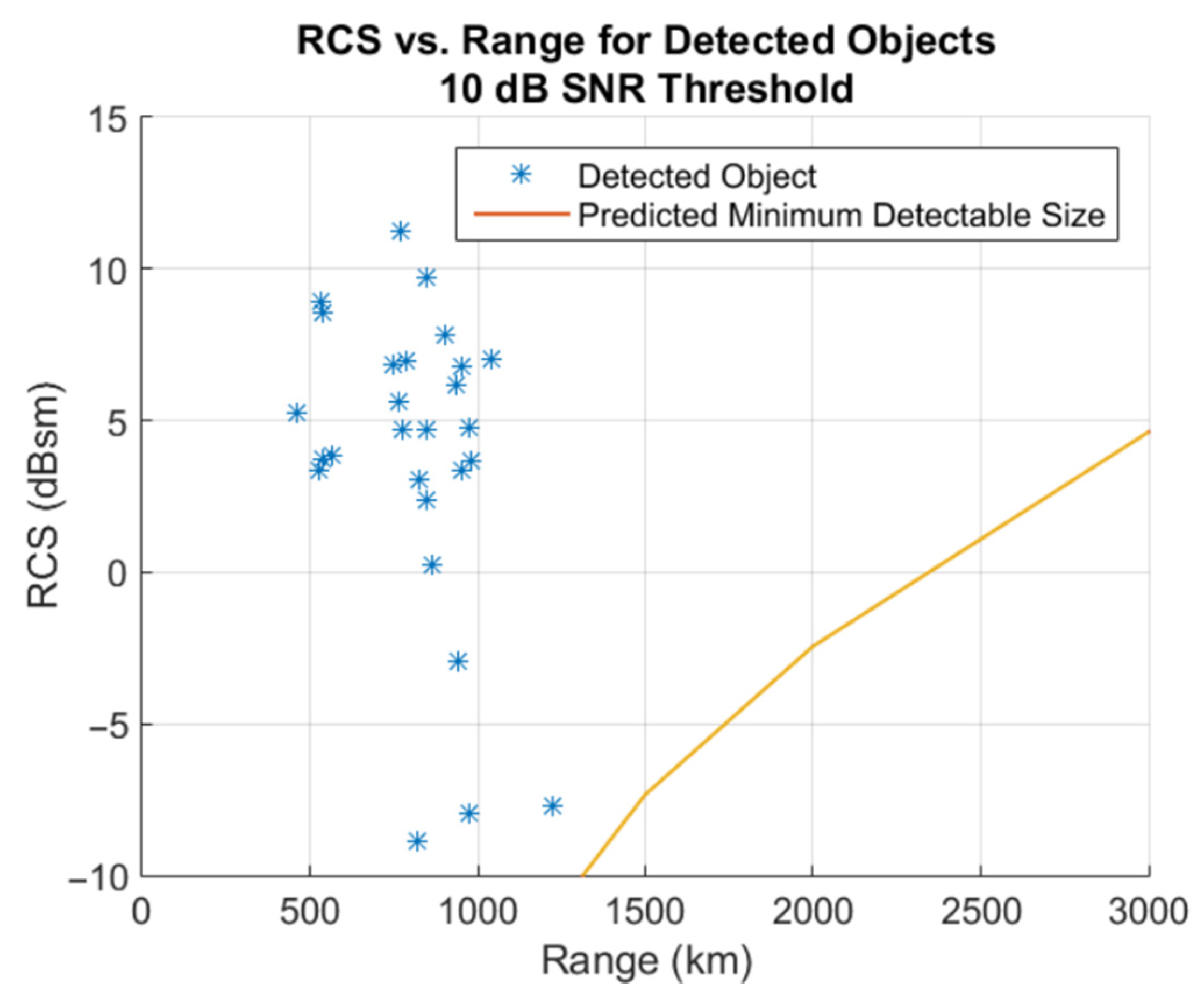
3. Results and Discussion

Between 13 December 2018 and 10 October 2019, the BIRALET system was able to observe a total of 27 objects. The Italian Air Force (Aeronautica Militare—AM) has provided the list of objects to observe, making sure to include a wide variety of samples in terms of RCS and range. All the observations were made in a variant of the beam-park mode. Usually, the beam-park mode (or stare mode) is employed for the survey of space debris, illuminating a specific portion of the sky and waiting for the objects to cross the field of view (FOV) of the antenna. It is employed very often to detect objects that are not part of a catalogue. In this case, the aim was not to detect uncatalogued objects, but to assess the capabilities of the radar system. Furthermore, the characteristics of the BIRALET system are not suitable for survey purposes, owing to the narrow beam. Thus, the antenna was pointed each time in a different direction, dictated by a specific object in the list, and waited for its passage. Before the observations, a forecasting simulation was made in order to obtain the azimuth and elevation pointing coordinates and to estimate the Doppler shift values. An algorithm based on the reading of the TLEs provides these pieces of information. The results of the campaign are summarized in Figure 6 and Figure 7, representing the RCS as a function of the range and the altitude as a function of the elevation pointing angle, respectively, for the 27 detected objects.
As expected, with reference to the scatter plot in Figure 6, the detected objects are located above the curve, representing the predicted minimum detectable size by the BIRALET system. This threshold value was obtained accounting for a minimum SNR of 10 dB (see Figure 3). It is worth noting that the SNR depends on many factors such as rotation of the object, materials, uncertainty in the values of the RCS and trajectory provided by the TLEs, pointing accuracy, and possible unwanted losses in the receiving chain. Moreover, especially in our case, where the transmitter is handled by a third part, the actual SNR can be difficult to estimate owing to unknown fluctuations of the transmitted power. For the above reasons, in this work, SNR was employed only for a first estimate of the system ability to detect a particular object.
The RCS of the detected objects varies between 0.13 m2 (−8.86 dBsm) and 13.4 m2 (11.27 dBsm), whereas the range varies between 459 and 1224 km. However, the majority of detections are clustered between 500 and 1000 km. From this image, it is clear that the BIRALET system would be capable of detecting even smaller objects, especially for low range values. Notwithstanding, the object with an RCS of 0.13 m2 is the smallest object ever detected by the bistatic radar, so far. During the reception of the scattered signals from the larger and/or closer objects, the receiving system did not suffer from saturation problems, thanks to an accurate setting of the digital step attenuator. From Figure 7, it can be inferred that all the spotted objects are located in the low Earth orbit (LEO), which includes altitudes between 200 and 2000 km. Detections on higher orbits are not feasible, owing to the relatively low power of the transmitter. However, almost every radar space debris sensor is focused on LEO measurements, as it is the most populated one.
As mentioned in Section 2, the data recorded by the back-end are acquired in a row format that can be later post-processed. These refined data are displayed in a spectrogram fashion, showing the duration of the passage, frequency, and power. An example of a time–frequency spectrogram is reported in Figure 8, for the object 4256, which is characterized by an RCS of 0.51 m2, an altitude of 918.1 km, and a range of about 941.5 km.
The passage of the objects within the beam of SRT is clearly recognizable thanks to its sweep in time and frequency. The thick line in the middle of the diagram (centered at 410.85 MHz) represents the carrier signal. Its presence is due to the relative proximity of the receiver with the transmitter of the BIRALET (the baseline of the bistatic radar is about 40 km). Actually, this peculiarity simplifies the interpretation of the measured Doppler frequency, which can be calculated from the frequency shift between the object echo and the carrier at the center of the visibility interval (which corresponds to 15:36:20 UTC in the given example). The measured Doppler frequency was retrieved for all of the objects and compared with the estimated one, showing a good agreement between the observed and predicted Doppler frequency. The maximum difference is in the order of magnitude of 1 kHz, the mean value of the difference is about 0.34 kHz, and the standard deviation is about 0.27 kHz. This comparison is reported in Table 2, for every object in the list, identifiable by its catalogue number (NORAD ID).

4. Conclusions and Future Works

In the last six years, the BIRALET system has been actively involved in the European space debris monitoring program, following an upgrade schedule that culminated in the installation of a dedicated receiving channel. Although the capabilities of the newly added channel have already been assessed in a recent paper [13], an extensive measurement campaign to test the real potential of the radar system was still lacking. In this paper, the most substantial radar measurement campaign for the BIRALET system is presented. Based on a list of objects provided by the Italian Air Force, the BIRALET has been able to detect a total of 27 objects with RCS ranging from 0.13 to 13.4 m2 in a range interval between 459 and 1224 km. In the future, this campaign will stand as a solid foundation for the next important step in the evolution of the BIRALET for space debris monitoring purposes: the tracking system. This new feature will enable the possibility to employ the BIRALET system for orbit determination of known and unknown objects in both single and joint campaigns with other Italian and European radar sensors.

Supplementary Materials

The following are available online at https://www.mdpi.com/2226-4310/8/3/86/s1.

Author Contributions

Conceptualization, T.P., G.M. (Giacomo Muntoni), and L.S.; methodology, T.P., G.M. (Giacomo Muntoni), L.S., and P.O.; validation, T.P., L.S., and P.O.; formal analysis, T.P., G.M. (Giacomo Muntoni), and G.M. (Giorgio Montisci); data curation, T.P., G.M. (Giacomo Muntoni), and G.M. (Giorgio Montisci); writing—review and editing, T.P., G.M. (Giacomo Muntoni), G.M. (Giorgio Montisci), and E.U.; supervision, G.M. (Giorgio Montisci). All authors have read and agreed to the published version of the manuscript.

Funding

This work was founded in part by the European Commission Framework Programme H2020 and Copernicus Space Surveillance and Tracking under grants 785257-2-3SST2016 and 237/G/GRO/COPE/16/8935-1SST2016.

Institutional Review Board Statement

Not applicable.

Informed Consent Statement

Not applicable.

Data Availability Statement

Data sharing not applicable.

Conflicts of Interest

The authors declare no conflict of interest.

References

  1. Xi, J.; Xiang, Y. Space Debris Detection Using Feature Learning of Candidate Regions in Optical Image Sequences. IEEE Access 2020, 8, 150864–150877. [Google Scholar] [CrossRef]
  2. European Space Agency. Space Operations—ESA and Space Debris; ESA Communication Production: Oakville, ON, Canada, 2013; ISBN 978-92-9221-059-5. [Google Scholar]
  3. Klinhrad, H. Space Debris—Model and Risk Analysis; Springer: Chichester, UK, 2006; pp. 199–205. [Google Scholar]
  4. Kennewall, J.A.; Vo, B. An Overview of Space Situational Awareness. In Proceedings of the 16th International Conference on Information Fusion, Istanbul, Turkey, 9–12 July 2013; pp. 1029–1036. [Google Scholar]
  5. Vallado, D.A.; Griesbach, J.D. Simulating Space Surveillance Networks. In Proceedings of the AAS/AIAA Astrodynamics Specialist Conference, Girdwood, AK, USA, 31 July–4 August 2011. [Google Scholar]
  6. Weeden, B.; Cefola, P.; Sankaran, J. Global Space Situational Awareness. In Proceedings of the Advanced Maui Optical and Space Surveillance (AMOS) Conference, Maui, HA, USA, 14–17 September 2010. [Google Scholar]
  7. Muntoni, G.; Pisanu, T.; Montisci, G.; Andronico, P.; Valente, G. Crowded Space: A Review on Radar Measurements for Space Debris Monitoring and Tracking. Appl. Sci. 2021, 11, 1364. [Google Scholar] [CrossRef]
  8. Pisanu, T.; Schirru, L.; Urru, E.; Gaudiomonte, F.; Ortu, P.; Bianchi, G.; Bortolotti, C.; Muntoni, G.; Montisci, G.; Protopapa, F.; et al. Upgrading the Italian BIRALES system to a Pulse Compression Radar for Space Debris Range Measurements. In Proceedings of the 22nd International Microwave and Radar Conference (MIKON), Poznan, Poland, 14–17 May 2018. [Google Scholar]
  9. Valente, G.; Iacolina, M.N.; Viviano, S.; Saba, A.; Serra, G.; Parca, G.; Impresario, G.; D’Amore, G.; Asmar, S.; Montisci, G.; et al. Sardinia Deep Space Antenna: Current Program Status and Results. In Proceedings of the International Astronautical Congress (IAC), Washington, MD, USA, 21–25 October 2019. [Google Scholar]
  10. Pisanu, T.; Concu, R.; Gaudiomonte, F.; Marongiu, P.; Melis, A.; Serra, G.; Urru, E.; Valente, G.; Portelli, C.; Bianchi, G.; et al. SRT as a Receiver in a Bistatic Radar Space Debris Configuration. In Ground-Based and Airborne Telescopes IV; International Society for Optics and Photonics: Bellingham, WA, USA, 2016; Volume 9906, p. 99060G. [Google Scholar]
  11. Muntoni, G.; Schirru, L.; Pisanu, T.; Montisci, G.; Valente, G.; Gaudiomonte, F.; Serra, G.; Urru, E.; Ortu, P.; Fanti, A. Space Debris Detection in Low Earth Orbit with the Sardinia Radio Telescope. Electronics 2017, 6, 59. [Google Scholar] [CrossRef] [Green Version]
  12. Schirru, L.; Muntoni, G.; Pisanu, T.; Urru, E.; Valente, G.; Gaudiomonte, F.; Ortu, P.; Melis, A.; Concu, R.; Bianchi, G.; et al. Upgrading the Sardina Radio Telescope to a Bistatic Tracking Radar for Space Debris. In Proceedings of the 1st IAA Conference on Space Situational Awareness (ICSSA), Orlando, FL, USA, 13–15 November 2017. [Google Scholar]
  13. Muntoni, G.; Schirru, L.; Montisci, G.; Pisanu, T.; Valente, G.; Ortu, P.; Concu, R.; Melis, A.; Urru, E.; Saba, A.; et al. A Space Debris-Dedicated Channel for the P-Band Receiver of the Sardinia Radio Telescope: A Detailed Description and Characterization. IEEE Antennas Propag. Mag. 2020, 62, 45–57. [Google Scholar] [CrossRef]
  14. Montisci, G.; Valente, G.; Muntoni, G.; Marongiu, P.; Pisanu, T. A Compact Q-Band Rectangular Waveguide Thermal Isolator. IEEE Trans. Microw. Theory Tech. 2020, 68, 611–619. [Google Scholar] [CrossRef]
  15. Doornbos, E.; Klinkrad, H.; Visser, P. Use of Two-Line Element Data for Thermosphere Neutral Density Model. Adv. Space Res. 2008, 41, 1115–1122. [Google Scholar] [CrossRef]
  16. Ladu, A.; Montisci, G.; Valente, G.; Navarrini, A.; Marongiu, P.; Pisanu, T.; Mazzarella, G. High-Performance Cryogenic Fractal 180° Hybrid Power Divider with Integrated Directional Coupler. Radio Sci. 2017, 52, 757–766. [Google Scholar] [CrossRef]
  17. Ladu, A.; Valente, G.; Montisci, G.; Mazzarella, G. A Wideband Quadruple-Ridged Horn Antenna for the Multifeed S-Band Receiver of the Sardinia Radio Telescope. J. Electromagn. Waves Appl. 2016, 30, 1207–1216. [Google Scholar] [CrossRef]
  18. Valente, G.; Marongiu, P.; Navarrini, A.; Saba, A.; Montisci, G.; Ladu, A.; Pisanu, T.; Pili, M.; Dessi, S.; Uccheddu, A.; et al. The 7-Beam S-Band Cryogenic Receiver for the SRT Primary Focus: Project Status. In Millimeter, Submillimeter, and Far-Infrared Detectors and Instrumentation for Astronomy VIII; International Society for Optics and Photonics: Bellingham, WA, USA, 2016; Volume 9914, p. 991422. [Google Scholar]
  19. Valente, G.; Montisci, G.; Pisanu, T.; Navarrini, A.; Marongiu, P.; Casula, G.A. A Compact L-Band Orthomode Transducer for Astronomical Receivers at Cryogenic Temperature. IEEE Trans. Microw. Theory Tech. 2015, 63, 3218–3227. [Google Scholar] [CrossRef]
  20. Valente, G.; Montisci, G.; Mariotti, S. High-Performance Microstrip Directional Coupler for Radio-Astronomical Receivers at Cryogenic Temperatures. Electron. Lett. 2014, 50, 449–451. [Google Scholar] [CrossRef]
  21. Bolli, P.; Olmi, L.; Roda, J.; Zacchiroli, G. A Novel Application of the Active Surface of the Shaped Sardinia Radio Telescope for Primary-Focus Operations. IEEE Antennas Wirel. Prop. Lett. 2014, 13, 1713–1716. [Google Scholar] [CrossRef]
  22. Skolnik, M.I. Radar Handbook, 2nd ed.; McGraw-Hill: Boston, MA, USA, 1990. [Google Scholar]
  23. Valente, G.; Orfei, A.; Nesti, R.; Navarrini, A.; Mariotti, S.; Bolli, P.; Pisanu, T.; Roda, J.; Cresci, L.; Marongiu, P.; et al. Status of the Radio Receiver System of the Sardinia Radio Telescope. In Millimeter, Submillimeter, and Far-Infrared Detectors and Instrumentation for Astronomy VIII; International Society for Optics and Photonics: Bellingham, WA, USA, 2016; Volume 9914, p. 991425. [Google Scholar]
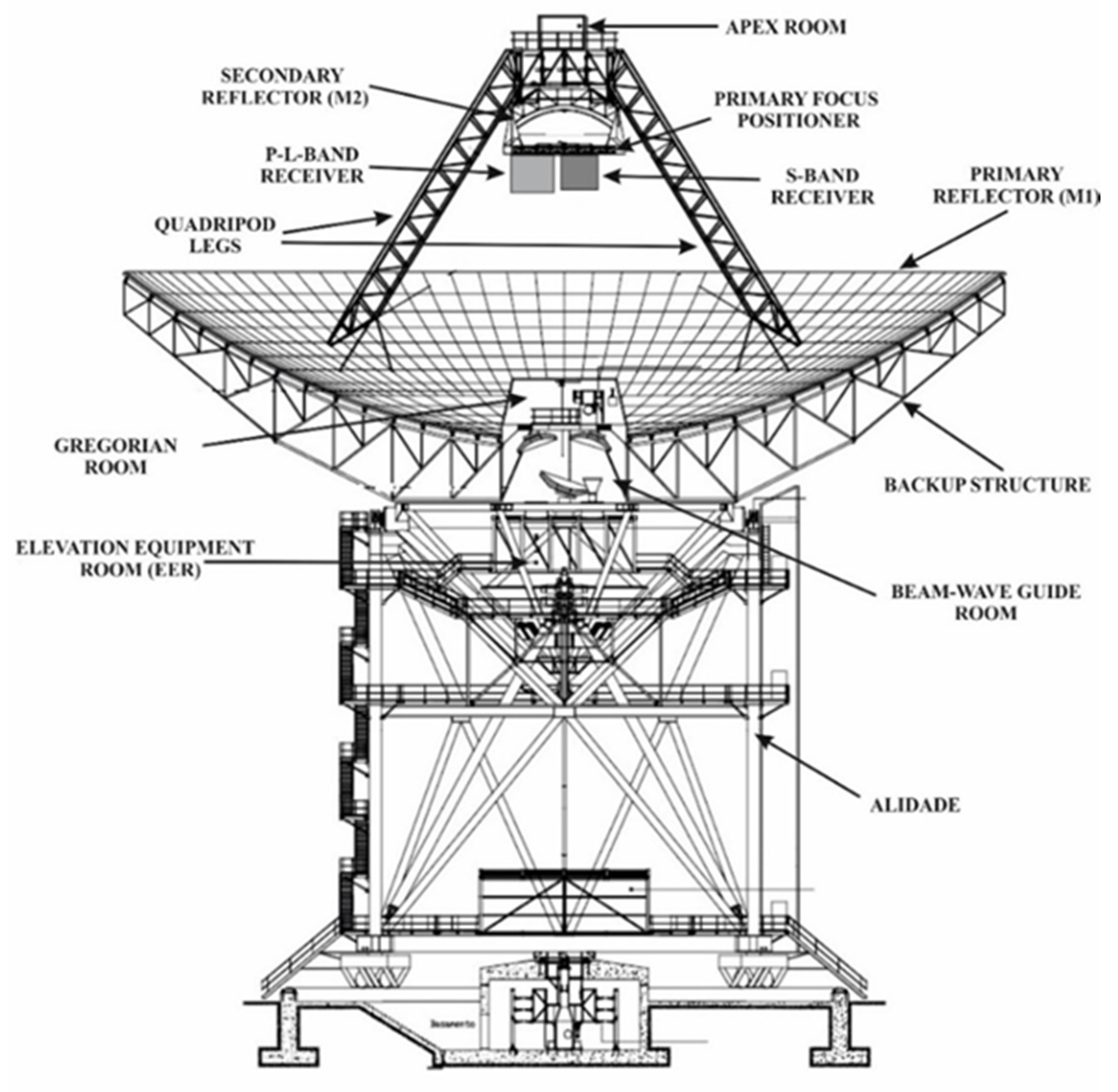
Figure 1. Photo of the Sardinia Radio Telescope (SRT).
Aerospace 08 00086 g001
Figure 2. Sketch of the Sardinia Radio Telescope.
Aerospace 08 00086 g002
Figure 3. Simulated received power at the antenna (SRT) as a function of the radar cross section (RCS) and range of the object for the Bistatic Radar for Low Earth Orbit (LEO) Tracking (BIRALET) system.
Aerospace 08 00086 g003
Figure 4. Radiation pattern of the SRT in P-band (410 MHz).
Aerospace 08 00086 g004
Figure 5. Schematic of the space debris dedicated channel of the SRT. RF, radio frequency.
Aerospace 08 00086 g005
Figure 6. Scatter plot of RCS vs. range for the detected objects with respect to the minimum detectable size by the BIRALET system. SNR, signal-to-noise ratio.
Aerospace 08 00086 g006
Figure 7. Scatter plot of altitude vs. elevation for the detected objects.
Aerospace 08 00086 g007
Figure 8. Spectrogram of the passage of the object 4256, registered on 19 May 2019.
Aerospace 08 00086 g008
Table 1. Key features of the Sardinia Radio Telescope (SRT). BWG, beam waveguide system.
OpticsGregorian (Shaped) + BWG
Focal PositionsPrimary: f/D = 0.33
Gregorian: f/D = 2.34
2 × BWG I: f/D = 1.38
2 × BWG II: f/D = 2.81
Frequency Range0.3–116 GHz
Primary Reflector Diameter64 m
Secondary Reflector Diameter7.9 m
BWG Mirrors Diameter2.9–3.9 m
Azimuth and Elevation Speed (wind speed < 60 km/h)0.85 °/s (Az)
0.5 °/s (El)
Antenna Gain at 410 MHz46.6 dBi
Antenna Efficiency at 410 MHz57.7%
Table 2. Estimated and measured Doppler shift for the 27 objects detected.
NORAD IDEstimated Doppler (kHz)Measured Doppler (kHz)Error—Absolute Value (kHz)
26102−7.96−7.440.52
361195.785.620.16
391944.224.440.22
154947.287.260.02
39452−8.66−8.820.16
39453−9.43−9.750.32
334928.498.160.33
30774−1.59−2.110.52
28931−5.85−4.661.19
3047−7.19−7.280.09
26222−3.63−3.490.14
279447.126.880.24
84583.533.400.13
63502.662.070.59
155957.807.420.38
365089.219.600.39
25482−6.31−6.480.17
11166−5.01−4.280.73
25105−7.69−8.040.35
4256−1.70−1.650.05
1328−4.04−3.300.74
7363−6.64−6.660.02
73374.874.900.03
228245.255.540.29
409619.599.920.33
12150−1.18−0.870.31
76464.645.360.72
Publisher’s Note: MDPI stays neutral with regard to jurisdictional claims in published maps and institutional affiliations.

