Article

Target Tracking Enhancement by Three-Dimensional Cooperative Guidance Law Imposing Relative Interception Geometry

1
College of Intelligence Science and Technology, National University of Defense Technology, Changsha 410073, China
2
The Institute of Effectiveness Evaluation of Flying Vehicle, Beijing 100085, China
*
Author to whom correspondence should be addressed.
Aerospace 2021, 8(1), 6; https://doi.org/10.3390/aerospace8010006
Submission received: 2 December 2020 / Revised: 21 December 2020 / Accepted: 22 December 2020 / Published: 28 December 2020

Abstract

:
The problem that two cooperative missiles intercept a maneuvering target while imposing a desired relative geometry is investigated in the paper. Firstly, a three-dimensional (3D) estimation model for cooperative target tracking is proposed and the observability of the missile-target range measurement is analyzed. In order to enhance the estimation performance, a two-level cooperative interception guidance architecture is proposed which combines a coordination algorithm with a novel 3D fixed-time convergent guidance law considering line of sight (LOS) angle constraints, such that the desired relative geometry can be imposed quickly and steadily by a dynamic strategy. The effectiveness and superiority of the proposed guidance law is evidenced through the numerical simulations comparing with other guidance laws.

1. Introduction

With the advancement of aerospace technology and industry, highly sophisticated aerial aerobats such as tactical ballistic missiles, hypersonic vehicles, and unmanned aerial vehicles pose severe challenges to the air-defense missile systems owing to their high maneuverability and weak observability [1]. Although the problem of intercepting a maneuvering target by a single intercept missile has been studied extensively over the past few decades, it is practically difficult and the interception performance is highly dependent on the interceptor’s acceleration capability and accurate knowledge of the target’s states, for example, velocity, acceleration etc. On the other hand, with the development of information processing system and wireless sensor network (WSN) technology, efficient and sustainable communication between multiple missiles is guaranteed, making it possible to carry out interception missions by multiple cooperative missiles. Compared with efforts to improve the performance of a single interceptor, cooperative interception by multiple interceptors can not only enhance the probability of a successful interception, but also accomplish many tasks which cannot be accomplished by a single missile, such as saturate the target’s defenses, cooperative tracking of target’s maneuvering mode, enhancement of electronic countermeasure effectiveness, etc. Therefore, the research of multi-missile cooperatively intercepting a maneuvering target has great engineering significance and received increasing attention at home and abroad.
Although different kinds of interceptors may be equipped with different seekers, the infra-red (IR) seekers are the most common, which has the merits of good interference immunity, low cost, and concealment, but it can only provide noisy bearing-only measurements. Because no information about the range is available, the target tracking performance is limited, especially in the presence of target maneuver, which may result in an unobservable system [2]. Take advantage of the concept of cooperative interception, the triangulation structure formed by the interceptor missiles and the target can be exploited to improve the estimation performance. Chen and Xu presented the double-LOS measuring relative navigation technique for spacecraft autonomous rendezvous and analyzed the observability issue by numerical method [3,4]. The work was introduced to the two-to-one interception engagement by Liu et al. [5]. With information sharing between the interceptor missiles, the range between the interceptor and target can be calculated respectively and serve as a pseudomeasurement to improve the estimation performance. The observability of the missile-target range, however, strongly depends upon the separation angle between the two interceptors relative to the target. As is analyzed in [3], when the separation angle becomes small (close to zero), the variance of the calculated range increases rapidly, making the triangulation technique fails and the estimation system unobservable. Therefore, the relative geometry between the missiles and target, and hence the implemented cooperative guidance laws have great influences on the estimation performance of cooperative target tracking.
Research on guidance laws with multiple constraints for a single missile is the theoretical basis of the multi-missile cooperative guidance problem, especially the guidance laws with impact time and angle constraints. Much research has been paid on cooperative guidance laws with angle constraints which can reduce the evasive probability of a maneuvering target. The existing cooperative guidance laws with angle constraints can be roughly classified into two categories. The first category is static guidance strategy [6], in which a pre-specified impact angle or LOS angle is set to each missile in advance and thereafter each missile is guidanced to target by its own guidance law independently. This approach is also sometimes denoted as offline cooperation because there is no communication between the missiles. Several guidance laws including types of bias or gain-varying proportional navigation guidance law [7,8,9], optimal guidance law(OGL) [10,11], and sliding mode guidance law(SMGL) [6,12,13], are proposed to impose the pre-specified angle in the scenarios of stationary or maneuvering target interception. As the interception is usually operated within short time, the convergence rate is an important performance index for evaluating the guidance law. Compared with the cooperative guidance laws in [7,8,9,10,11], the finite-time convergent cooperative guidance law [6,12,13] based on sliding mode control has faster convergence rate and higher guidance precision, but its convergence time is seriously affected by the initial states of the missiles [14]. If the initial states are unavailable, the settling time cannot be estimated prior. Furthermore, when the initial conditions are poor, the convergence time may be longer than the engagement time, which greatly degrades the guidance efficiency [15]. To cope with the problem, based on the wide application of fixed-time convergent control method in multi-agent systems, a novel fixed-time convergent cooperative guidance law for attacking a stationary target was proposed in [16]. The upper bound of setting time is independent of initial conditions, which ensures the efficiency of cooperative guidance in any initial states. Nevertheless, the research about fixed-time cooperative guidance law with angle constraints is rarely yet.
Although the aforementioned guidance laws can achieve the desired angle constraints, they are unable to address the relative geometry between the missiles and target and can not take advantage of the intrinsic relationships between the cooperating missiles during the engagement. Unlike the static guidance strategy, the dynamic guidance strategy, also referred as online cooperation, has no need to set the angle constraints in advance. The missiles exchange information with each other to achieve the the desired relative geometry during the process of guidance. Shaferman and Shima first developed a two-dimensional (2D) dynamic cooperation guidance law imposing a relative intercept angle in the linear quadratic framework, by introducing relative angular differences into the cost function of the optimization problem [17]. Similar method was utilized in [1], where two interceptors defended an aircraft against an attacking homing missile, through imposing nonnegative relative intercept angle constraints between consecutive defenders to improve the observability. However, the 2D linear framework in their work can not suit the practical 3D engagement scenario.
When the interceptor missiles intercept a maneuvering target, the engagement scenario is, in fact, a 3D one. Most of the existing papers decouple the 3D interception space geometry into two mutually orthogonal 2D ones, after that, the estimation and guidance models are developed in each plane separately. Though the design process can be simplified, the decoupling may lose part of the guidance information and degrade the performance when in practical engagement operations, especially for intercepting a high maneuvering target. In recent years, increasing attention has been paid to develop estimators and guidance laws with the coupled 3D nonlinear model, nevertheless, to the best of our knowledge, the 3D cooperative interception problem of imposing relative interception geometry to enhance the performance of target tracking was not addressed before.
Motivated by the previous discussion, this study aims at developing a 3D cooperative interception guidance law to impose a desired relative geometry between the missiles and target, and thus enhance the estimation performance of cooperative target tracking. Inspired from the two-level cooperative guidance structure for multimissile simultaneous attack presented by [18], a general coordination algorithm which can decompose the desired relative interception geometry into the constraints of LOS angles for the cooperative missiles is presented, combined with the proposed local guidance law which is based on integral sliding mode control and can impose the required LOS angles within fixed time. The contributions of this study are summarized as the following three aspects.
  • The 3D maneuvering target tracking model is proposed without omitting the couplings between the elevation and the azimuth channels, the effect of the relative geometry on the observability of the missile-target range is analyzed in quantity.
  • Based on convex optimization theory, a general coordination algorithm is proposed and the constraint of the relative geometry between the missiles and target is decomposed into the LOS angle constraints considering the input saturation.
  • Based on fixed-time convergent control method and integral sliding mode control theory, a novel 3D fixed-time integral sliding mode guidance law (FxTISMGL) with LOS angle constraints is developed for the first time. The proposed 3D guidance law is more practical than the 2D ones and has a faster convergence rate.
The remainder of this paper is organized as follows. In Section 2, the mathematical three-dimensional estimation model for cooperative target tracking is proposed. Thereafter, the two-level dynamic cooperative interception guidance structure for relative geometry imposing is presented in Section 3, and in Section 4, numerical experiments and analyses are shown. Finally, conclusions are drawn in Section 5.

2. Formulation of Three-Dimensional Estimation Model

In this section, the mathematical three-dimensional estimation model for cooperative target tracking is established. The scenario considered here contains three bodies: two missiles and an aerial target. It is assumed that each missile is equipped with an inexpensive IR sensor, which can measure the corresponding LOS angles with respect to the target only. The interceptor-missile relative motion equations and measurement model for cooperative estimation are proposed, and assumptions in the derivation are also addressed.

2.1. Kinematics and Dynamics

The 3D engagement scenario is shown in Figure 1. The missiles and target are denoted as M and T, respectively. M X Y Z denotes the inertial reference frame; r represents the relative distance between the interceptor and the target; ϕ and θ represent the LOS elevation and azimuth angles, respectively. ( r , θ , ϕ ) forms the spherical LOS reference frame.
The coupled 3D relative motion model for the ith missile can be described by the differential equations as follows [19,20]:
r ¨ i = r i θ ˙ i 2 cos 2 ϕ i + r i ϕ ˙ i 2 + a T r i a M r i ϕ ¨ i = 2 r ˙ i ϕ ˙ i r i θ ˙ i 2 sin ϕ i cos ϕ i + a T ϕ i a M ϕ i r i θ ¨ i = 2 r ˙ i θ ˙ i r i + 2 θ ˙ i ϕ ˙ i tan ϕ i + a T θ i a M θ i r i cos ϕ i
Assumption 1.
As the IR seekers have a minimum effective action distance R 0 , it is reasonable to assume r i > R 0 throughout the interception process. Furthermore, we can always have ϕ i π 2 , π 2 by choosing appropriate coordinate systems. Therefore, there is no singularity in the dynamics Equation (1).
It is assumed that the dynamics of the target’s maneuver during the engagement can be represented by first order differential equations with unknown uncertainties.
a ˙ T r i = 1 τ a T r i + ω T r i a ˙ T ϕ i = 1 τ a T ϕ i + ω T ϕ i a ˙ T θ i = 1 τ a T θ i + ω T θ i
where τ is the time constant of the target dynamics, and ω represents the unknown uncertainties.
In this paper it is assumed that ω is a zero-mean white Gaussian noise process and the spectral density Q i is given as the jerk process intensity [21]
Q i = a T max 2 t i , F
where t i , F is the flight time of the ith interceptor during the engagement.
Choose T as the sampling time. At time t k , the equivalent discrete process noise matrix Q i , k 1 can be calculated as
Q i , k 1 = 0 T ϕ i , k k 1 Q i ϕ i , k k 1 T d t
where ϕ i , k k 1 is the transition matrix associated with the relative motion model.

2.2. Measurement Model

As was previously assumed, the LOS elevation angle ϕ and azimuth angle θ between the missile and target can be measured by the IR sensor equipped in each missile, contaminated by zero-mean white Gaussian measurement noises υ ϕ and υ θ , with standard deviation δ ϕ and δ θ , respectively. The measurement noises are assumed to be mutually independent for the two LOS angles, and apparently independent for the two missiles; therefore, E ( υ ϕ υ θ ) = 0 and E ( υ 1 υ 2 ) = 0 . Thus, the measurement equation of the ith missile performed by using its own-ship measurement only without information sharing (noted by no-sharing mode) is as follows:
z i , 1 z i , 2 = h i , 1 x i h i , 2 x i + v ϕ i v θ i = ϕ i + v ϕ i θ i + v θ i
where v ϕ i N 0 , σ ϕ i 2 , v θ i N 0 , σ θ i 2
Remark 1.
As the IR sensor measures the angle between the boresight and the LOS, the measurements are selected to be the LOS angles ϕ and θ directly on the assumption that the IR sensor is equipped in a tracking and stable platform, which can guarantee that the sensor tracks the target and outputs the required information after some basic pretreatments.
The range between the missile and target cannot be measured by the IR sensor, but can be calculated by virtue of the double-LOS measuring relative navigation technique for the many-to-one interception engagement. The work is extended to three-dimensional space here. As is shown in Figure 1, the two missiles form a measuring baseline relative to the target in space. In addition to the measurement of LOS angles of the target, it is assumed that the two missiles can share their own inertial states ( p i x , p i y , p i z ) with each other, which can be accurately obtained by the inertial navigation system for most missiles.
The position vector between the two missiles can be expressed as:
r i j = r j i = p j x p i x p j y p i y p j z p i z
where the subscript j represents the other missile from the subscript i in this paper.
Although the position vectors of the target relative to the ith missiles cannot be obtained without the measurement of the ranges, its unit can be expressed with the LOS angles as follows:
r i = cos ϕ i cos θ i cos ϕ i sin θ i sin ϕ i
In the plane determined uniquely by the two missiles and target, the space angle between the vectors r i and r ji is calculated as follows:
γ i = arctan r j i × r i r j i r i
Apparently, the separation angle between the two LOS vectors is:
γ i j = π γ i γ j
Application of the sine theorem in the determined plane yields the pseudo-measurement r ^ i :
r ^ i = r i j sin γ j sin γ i j
Therefore, the third measurement equation of the missile is:
z i , 3 = h i , 3 x i + v r ^ i = r ^ i + v r ^ i v r ^ i N 0 , σ r ^ i 2
The standard deviation of the distances can be obtained by the approximate method for variance propagation of the nonlinear function:
σ r ^ , i = r i j sin 2 γ i σ γ j 2 + sin 2 γ j cos 2 γ i j σ γ i 2 sin 2 γ i j
where
σ γ i = γ i ϕ i 2 σ ϕ i 2 + γ i θ i 2 σ θ i 2
and
γ i ϕ i = p j i x sin ϕ i cos θ i + p j i y sin ϕ i sin θ i p j i z cos ϕ i r i j 2 p j i x cos ϕ i cos θ i + p j i y cos ϕ i sin θ i + p j i z sin ϕ i 2
γ i θ i = p j i x cos ϕ i sin θ i p j i y cos ϕ i cos θ i r i j 2 p j i x cos ϕ i cos θ i + p j i y cos ϕ i sin θ i + p j i z sin ϕ i 2
the p j i x , p j i y , p j i z represent the projection of r i j in the three axes of the inertial reference frame.
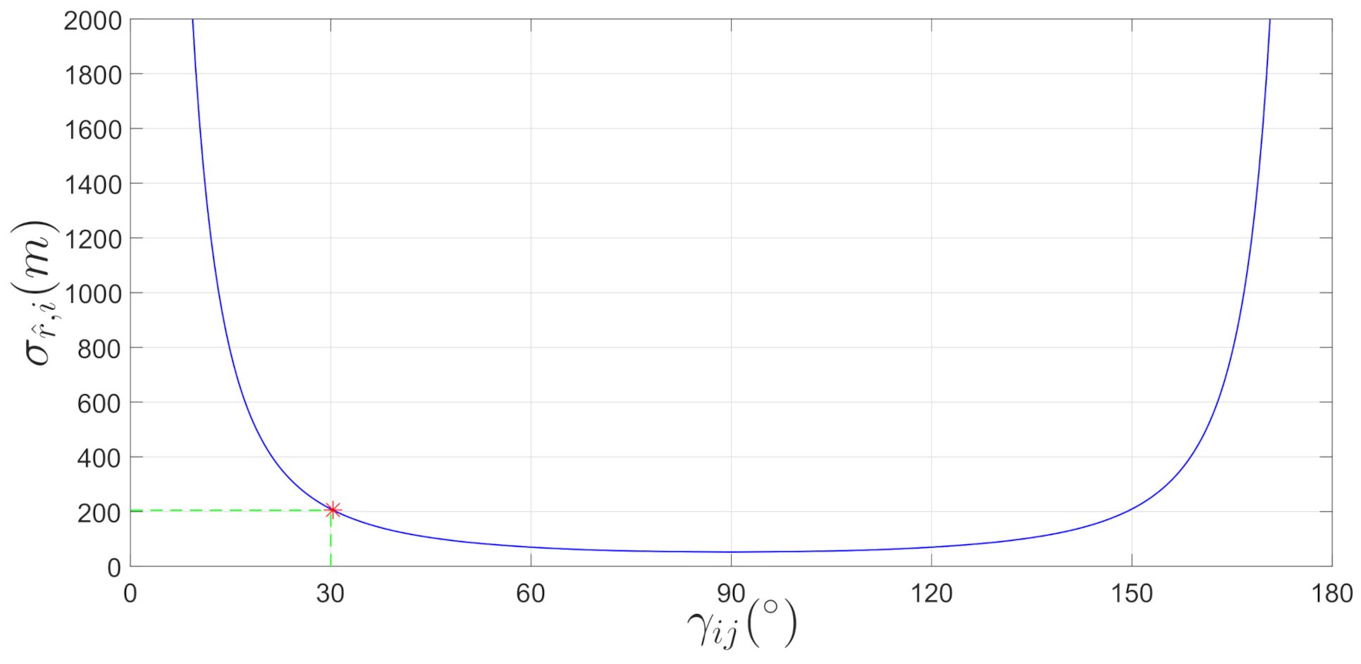
Corresponding to the analyses in [3], from Equation (12), it is conspicuous that, if the separation angle for the two missiles relative to the target becomes small (close to zero), the variance of the pseudomeasurement r ^ for both missiles increases, the estimation accuracy may degrade. However, excessive emphasis on enlarging the separation angle may affect the performance of the guidance law, especially if the missiles are close to each other at the beginning of the engagement. Assume σ γ i = σ γ j = 0.3 , r i j = 10 km, for each γ i j , the value of m a x ( σ r ^ ) can be calculated because of γ i j = π γ i γ j , and the curve of m a x ( σ r ^ ) with γ i j given r i j = 10 km is shown in Figure 2. It can be observed that as long as the separation angle is not bigger than 30 , the variance of r ^ increases slowly and is quite acceptable.
Finally, the cooperative measurement model with information sharing is summarized as follows:
z i = h i x i + v i
and
z i = z i , 1 z i 2 z i , 3 T v i = v ϕ i v θ i v r ^ i T N 0 3 × 1 , R
where
R = R 1 , 1 r ^ ϕ i σ ϕ i r ^ θ i σ θ i r ^ ϕ i σ ϕ i σ ϕ i 2 0 r ^ θ i σ θ i 0 σ θ i 2
R 1 , 1 = r i j 2 sin 2 γ i σ γ j 2 sin 4 γ i j
r ^ i ϕ i = r ^ i γ i · γ i ϕ i = r i j sin γ j cos γ i j sin 2 γ i j · γ i ϕ i
r ^ i θ i = r ^ i γ i · γ i θ i = r i j sin γ j cos γ i j sin 2 γ i j · γ i θ i
where γ i ϕ i and γ i θ i are derived as Equations (14) and (15).
Remark 2.
Despite the widespread usage of the KF-based filters, such as extended Kalman filter (EKF), unscented Kalman filter (UKF) and cubature Kalman filter (CKF), there is a challenging issue in actual applications that their estimation performance depend heavily on the determination of the covariance matrices of the process and measurement noise characteristics. In practice, this is usually done rely on experience and in an ad hoc trial-and-error manner. However, improper choice of these matrices may lead to bias estimation, unreliable uncertainty estimation and even divergence problems [22]. In this paper, the theoretical values of the covariance matrices are calculated with reference to [21], which has been shown mathematically equivalent of a target maneuver with random starting time. It is worth noting that, unlike this kind of offline scheme, various methods have been proposed to estimate and update the noise covariance matrices online based on the residuals [23] or Bayesian techniques [22,24,25].
To address the strong nonlinearity in the three-dimensional estimation model, the tracking algorithm is chosen as CKF [26], which is the closest approximation algorithm to Bayesian filtering in practical application and has been proved to achieve third order or higher precision. The implementation process of the standard CKF algorithm is given in Appendix A.

3. Two-Level Cooperative Interception Guidance Structure

The main object of the guidance is to design a M for the cooperative missiles to impose a desired relative geometry between the missiles and target to enhance the tracking performance of the target. To be specific, as is analyzed in Section 2, the object is to design a M for the cooperative missiles to enlarge the separation angle to desired valuable as soon as possible at the beginning of the engagement and then keep the desired relative geometry until the target is intercepted.
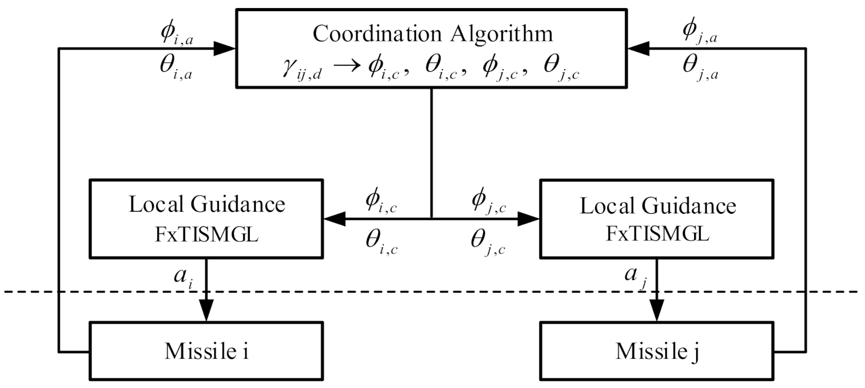
The two-level cooperative guidance structure for multimissile simultaneous attack in [18] is extended here to achieve dynamic cooperation for the missiles to impose the desired separation angle between the cooperative missiles relative to the target. The dynamic cooperative guidance architecture for relative geometry imposing is presented in Figure 3.
The actual LOS angles of the missiles ϕ i , a , θ i , a , ϕ j , a , θ j , a at time t is collected by information sharing between the missiles. Then the LOS angle commands corresponding to the desired γ i j , d is calculated by the coordination algorithm and sent to the cooperative missiles. The acceleration command a i , a j are obtained by the proposed local guidance law and implemented on each missile separately.
Firstly, the coordination algorithm is proposed as following in this section. Thereafter, the design process of a novel 3D integral sliding mode guidance law with LOS angle constraints is presented and the proof of fixd-time convergence is given.

3.1. Coordination Algorithm Based on Convex Theory

Similar with Equations (8) and (9), the space separation angle between the missiles relative to the target can be also calculated as follows
γ i j = arccos r i r j r i r j = arccos cos ϕ i cos ϕ j cos θ i θ j + sin ϕ i sin ϕ j
From Equation (22), we can see that the separation angle is determined uniquely by the LOS angles ϕ and θ of the two cooperative missiles. So the object can be achieved by imposing the LOS angles to appropriate values. From Equation (1), and neglect the couplings yields:
ϕ ¨ i = 2 r ˙ i ϕ ˙ i r i + a T ϕ i r i a M ϕ i r i θ ¨ i = 2 r ˙ i θ ˙ i r i + a T θ i r i cos ϕ i a M θ i r i cos ϕ i
It can be seen that with the divisor of cos ϕ i , which is rather smaller than 1 in most scenarios, the control efficiency of control input a M θ i to the azimuth angle θ i is much higher than that of the control input a M ϕ i . Therefore, assume the adjustment of the elevation angle ϕ i is small during the process of the forming of the desired relative geometry, then we have cos ϕ i w i , the parameter w i is a positive constant.
Define the initial the LOS angles are ϕ i , 0 and θ i , 0 , i = 1 , 2 , and the separation angle γ i j , 0 is calculated by Equation (22). Consider decomposing the desired separation angle into the constraints for the LOS angles of the two cooperative missiles, while minimizing the effort of all the missiles, the problem can be formed as
min ϕ , θ J = i = 1 2 w i 2 ϕ i , d ϕ i , 0 2 + θ i , d θ i , 0 2
subject to
cos γ 12 , d = cos ϕ 1 , d cos ϕ 2 , d cos θ 1 , d θ 2 , d + sin ϕ 1 , d sin ϕ 2 , d
ϕ i , d π 2 , π 2 ,   θ i , d π 2 , π 2 ,   i = 1 , 2
Although the equality constraint Equation (25) is nonconvex in the whole domain of definition, we can divide the definition domain into several spans and in each span the constraint is convex. Then, the convex optimization method can be applied and the optimal solution can be obtained, which is the desired LOS angle constraints for the cooperative missiles. In this paper, the problem is solved by the interior-point algorithm.
Take the input saturation into consideration, we divide the constraint of LOS angles into a sequence of commands to the guidance by a time variant adaptive method. What is more, from Equtaion (23) we can see, as the derivation of the missile-target range is usually negative, the division is beneficial for the implementation of the constraint of the LOS angles. The adaptive method is defined as follows
x c t = t d t p x a t + p x d t d t
where x a t denotes the actual LOS angle and x c t is the command LOS angle at time t, x d denotes the desired LOS angle calculated from Equations (24)–(26), t d is the desired time before when we hope the desired geometry is imposed, and t d t = p , if t d t < p , we can see from Equation (27) that when t d t = p , x c t = x d .

3.2. Fixed-Time Convergent Guidance Law Design

3.2.1. Definitions and Lemmas

Definition 1
([27,28]). Consider a nonlinear system in the form of
x ˙ = f x , t , f 0 , t = 0 , x R n
where f : U 0 × R R n is continuous on U 0 × R , and U 0 is an open neighborhood of the origin x = 0 , R is the set of real numbers. The state of the system is said to converge to its local equilibrium x = 0 in finite time if, for any given initial time t 0 and initial state x t 0 = x 0 U , there exists a settling time T 0 , which is dependent on x 0 , such that every solution of the system Equation (A11), x t = φ t ; t 0 , x 0 U / 0 , satisfies
lim t T x 0 φ t ; t 0 , x 0 = 0 , φ t ; t 0 , x 0 = 0 , i f t > T x 0
Moreover, if the system (local) equilibrium x = 0 is Lyapunov stable with finite time convergence in a neighborhood of the origin U U 0 then the system equilibrium is called finite time stable. If U = R n , then the origin is a global finite time stable equilibrium.
Lemma 1
([27]). Consider the nonlinear system described by Equation (A11). Suppose that there is a C 1 (continuously differentiable) function V x , t defined in a neighborhood U R n of the origin, and that there are real numbers α > 0 and 0 < 1 < λ , such that V x , t is positive-definite on U and that V ˙ x + α V λ x , t 0 on U . Then, the zero solution of system (A11) is finite-time stable and the settling time is given by
t r V x 0 , 0 1 λ α 1 λ
It can be seen that the finite settling time estimate Equation (A12) depends on the system initial states, which restricts the practical applications since the knowledge of initial conditions may be unavailable in advance. Furthermore, if the initial conditions are poor, the convergence time may exceed the engagement time and degrade the guidance performance. Moving further on, Polyakov [29] put forward a fixed-time stability concept as follows.
Definition 2.
The origin is said to be a ‘fixed-time stable’ equilibrium point of (1) if it is globally finite-time stable and the settling time function T x 0 is bounded, that is, there exists T max > 0 independent on the initial state, such that T x 0 T max , x 0 R n .
Lemma 2
([30]). If there exists a continuous radially unbounded function V : R n R + 0 such that (1) V x = 0 x = 0 and (2) any solution of (1) satisfies the inequality D * V x t α V p x t β V q x t where α > 0 ,   β > 0 and p > 1 > q > 0 , then the origin is globally fixed-time stable and the settling time function T x 0 is uniformly bounded by a computable constant, i.e.,
T x 0 T max : = 1 α p 1 + 1 β q 1
Lemma 3
([31]). Consider a system with
x ˙ = a x m / n b x p / q , x ( 0 ) = x 0
where the parameters m,n,p, and q are all odd integers satisfying q > p > 0 and m > n > 0 , a > 0 and b > 0 . Then the equilibrium of (32) is globally finite-time stable and the settling time is bounded by
T T max = 1 b m 1 1 ln a + b a + 1 a 1 m 2 ln a + b b
Lemma 4
([32]). Consider a second-order system
x 1 = x 2 x 2 = u
where x 1 and x 2 are the system’s states with the assumption of being measurable, the control u is proposed by
u ( x ) = i = 1 2 k i x i σ i + x i + x i i
where x σ = x σ s i g n x , the parameters k i > 0 , ( i = 1 , 2 ) are selected to guarantee the second-order polynomials s 2 + k 2 s 1 + k 1 and s 2 + 3 k 2 s 1 + 3 k 1 are Hurwitz, and σ 2 j = σ ( j + 1 ) i σ , σ 2 j = 2 σ j σ ( j 1 )   ( j = 0 , 1 ) , where σ ( ε , 1 ) with ε 1 2 , 1 . Then, through the bi-limit homogeneous technique, the equilibrium of system (34) is fixed-time stable.

3.2.2. The Design of Fixed-Time Convergent Guidance Law with LOS Angle Constraints

Without loss of generality, neglect the subscript i for brevity; define x 1 = ϕ ϕ c , x 2 = ϕ ˙ , x 3 = θ θ c , x 4 = θ ˙ and combining Equation (1) yield the three-dimensional guidance system described as follows:
x ˙ 1 = x 2 x ˙ 2 = 2 r ˙ x 2 r x 4 2 sin x 1 cos x 1 + a T ϕ a M ϕ r x ˙ 3 = x 4 x ˙ 4 = 2 r ˙ x 4 r + 2 x 2 x 4 tan x 1 + a T θ a M θ r cos x 1
Assumption 2.
Suppose that the target’s acceleration is bounded, a T θ < d 1 and a T ϕ < d 2 , where d 1 and d 2 are positive constants.
Design the sliding surface vector as
s = s 1 s 2 = t 0 t f k 1 x 1 σ 11 + x 1 + x 1 σ 12 + k 2 x 2 σ 21 + x 2 + x 2 σ 22 d t + x 2 x 2 t 0 t 0 t f k 3 x 3 σ 31 + x 3 + x 3 σ 32 + k 4 x 4 σ 41 + x 4 + x 4 σ 42 d t + x 4 x 4 t 0
where, σ 21 = σ 0 , 1 , σ 11 = σ 2 σ , σ 12 = 4 3 σ 2 σ , σ 22 = 4 3 σ 3 2 σ , σ 41 = σ ¯ 0 , 1 , σ 31 = σ ¯ 2 σ ¯ , σ 32 = 4 3 σ ¯ 2 σ ¯ , σ 42 = 4 3 σ ¯ 3 2 σ ¯ , k i > 0   i = 1 , 2 , 3 , 4 , t 0 and t f represent the start time and end time of the interception respectively.
With the time derivative of (37) We can obtain
s ˙ = s ˙ 1 s ˙ 2 = k 1 x 1 σ 11 + x 1 + x 1 σ 12 + k 2 x 2 σ 21 + x 2 + x 2 σ 22 + x ˙ 2 k 3 x 3 σ 31 + x 3 + x 3 σ 32 + k 4 x 4 σ 41 + x 4 + x 4 σ 42 + x ˙ 4 = A + Bu + Cd
where A = a 1 a 2 , B = C = 1 r 0 0 1 r cos x 1 , u = a M ϕ a M θ , d = a T ϕ a T θ ,
a 1 = 2 r ˙ x 2 r x 4 2 sin x 1 cos x 1 + k 1 x 1 σ 11 + x 1 + x 1 σ 12 + k 2 x 2 σ 21 + x 2 + x 2 σ 22
a 2 = 2 r ˙ x 4 r + 2 x 2 x 4 tan x 1 + k 3 x 3 σ 31 + x 3 + x 3 σ 32 + k 4 x 4 σ 41 + x 4 + x 4 σ 42
According to Assumption 2, the term Cd can be viewed as bounded external disturbances Cd Δ , where Δ = c o n s t . > 0 .
Theorem 1.
Consider the nonlinear guidance system of 3D relative motions Equation(1) with the vectorial integral sliding mode surface (37), under the guidance algorithm Equation(39) and Assumption 1. Then the LOS angle errors, x 1 and x 3 can converge to zero within a fixed time, respectively.
u = a M ϕ a M θ = B 1 A + a s m / n + b s p / q + s s Δ
where s λ = s 1 λ , s 2 λ T , λ > 0 , m, n, p and q are positive odd integers satisfying p > q , n > m , a > 0 , and b > 0 .
Proof. 
A Lyapunov candidate is constructed as:
V = 1 2 s T s
the time derivative of V along (38) and (39) gives
V ˙ ( s ) = s T s ˙ = s T ( A + Bu + Cd ) = a ( s ) m n + 1 b ( s ) p q + 1 + s ( C d Δ ) a ( s ) m n + 1 b ( s ) p q + 1 = 2 a ( V ) m + n 2 n 2 b ( V ) p + q 2 q
On the basis of Lemma 1, the vectorial sliding mode surface s = 0 can be achieved in a fixed time T 1 . By letting s ˙ = 0 , the equivalent dynamics on the sliding manifold can be represented as:
x ˙ 2 = k 1 x 1 σ 11 + x 1 + x 1 σ 12 k 2 x 2 σ 21 + x 2 + x 2 σ 22
x ˙ 4 = k 3 x 3 σ 31 + x 3 + x 3 σ 32 k 4 x 4 σ 41 + x 4 + x 4 σ 42
Similar to the proof of Lemma 4 [33], based on the LaSalle’s invariance principle, system Equation (36) is fixed-time stability, assume x 1 and x 3 converge to the zeros in a globally bounded time T 2 , the total settling time of the guidance system for the ith missile can be calculated by T i < T 1 + T 2 . □
Therefore, with the acceleration command in Theorem 1, all the missiles can impose the desired LOS angles after T = m a x ( T i ) , which depends on the related parameters. Therefore, by adjusting the related parameters, when the flight time t > T multiple missiles can achieve cooperative interception with LOS angle constraints against a maneuvering target.

4. Experimental Results and Analysis

The performance of the proposed three dimensional cooperative interception guidance law is evaluated in this section via numerical simulation, using the nonlinear kinematics dynamics for the missiles and target. The simulation environment is presented first, followed by an interception scenario involving two missiles and a target to demonstrate the superiority of the proposed guidance law comparing with the other guidance laws.

4.1. Simulation Environment and Scenario

The simulation includes two interceptor missiles and an aerial target. The engagements are initialized at the terminal phase of the interception, with the missiles separated on both sides of the target. Initial conditions of the interceptors and the target are given in Table 1.
The maximal maneuver capability of the missiles and the target is a M m a x = 50 g, and a T m a x = 2 g along the three axes in the LOS coordinate system, respectively. The equations of motion of the missiles and the target are solved through the fourth-order Runge-Kutta algorithm and the time step is chosen as 0.001 s. It is supposed that each missile is equipped with an IR sensor missile, which can only provide measurement of LOS angles and the measurement noise is 0.3 .
The target performs three typical dynamics along the three axes in the LOS coordinate system. As the projection of the target acceleration is different between the two missiles, we set the target acceleration in the 1st missile’s LOS coordinate system as follows:
a T r 1 = 0 a T ϕ 1 = 10 sin ( t / 3 ) a T θ 1 = 10 s i g n sin ( t / 3 )
then the target acceleration in the 2st missile’s LOS coordinate system can be easily calculated by the transition matrix.
The missiles perform a minor adjustment along r i referred from [34] to achieve simultaneous interception
a M r i = N 1 r i r ˙ i r j r ˙ j
Meanwhile, in the directions of the two LOS angles, to testify the superiority of the proposed FxTISMGL, the adaptive sliding mode guidance law (ASMGL) presented in [35] and the nonlinear finite-time convergent sliding mode guidance law (NFTSMGL) deduced in [6] are simulated under the same conditions. The ASMGL is selected as
u A S M G L = a M ϕ i a M θ i = N 2 r ˙ i ϕ ˙ i + N 3 s ign ϕ ˙ i N 2 r ˙ i θ ˙ i + N 3 s ign θ ˙ i
And the NFTSMGL is expressed as
u N F T S M G L = a M ϕ i a M θ i = B i 1 A i + k 1 s + k 2 sig μ ( s ) + sign ( s ) Δ + D
where
A i = 2 r ˙ i r i ϕ ˙ i θ ˙ i 2 sin ϕ i cos ϕ i 2 r ˙ i r i θ ˙ i + 2 ϕ ˙ i θ ˙ i tan ϕ i B i = 1 r i 0 0 1 r i cos ϕ i s = x 3 i + α sig λ 1 x 3 i + β sig λ 2 x 4 i D = β 1 λ 2 1 diag x 4 i 2 λ 2 I 2 + α λ 1 diag x 3 i λ 1 1 sign x 4 i
the parameters Δ = c o n s t . > 0 , α , β > 0 , 1 < λ 2 < 2 , λ 1 > λ 2 , 0 < μ < 1 , and k 1 , k 2 > 0 .
In the practical situation, the inevitable noises, disturbances, and uncertainties may aggravate the chattering caused by the signum function, which may have a bad influence on the guidance system. To alleviate the chattering phenomenon, an effective way is to adopt the boundary-layer technique by replacing the signum function with a continuous saturation function s a t δ ( x ) , depicted by
s a t δ x = 1 , x > δ x / δ ,    x δ 1 , x < δ
where δ is a small positive constant helps construct a boundary layer x δ to approximate the ideal x = 0 .
For evaluating the guidance performance under the same condition, closed loop scheme is employed and the desired separation angle is set as 35 . Because the initial elevation angle ϕ for both missile is approximately equal to 30 , we set the weight w i = 4 , i = 1 , 2 . Both the NFTSMGL and proposed FxTISMGL work together with the coordination algorithm to achieve dynamic cooperation, and the commanded missile accelerations are all saturated by a M m a x .

4.2. Simulation Results and Comparison

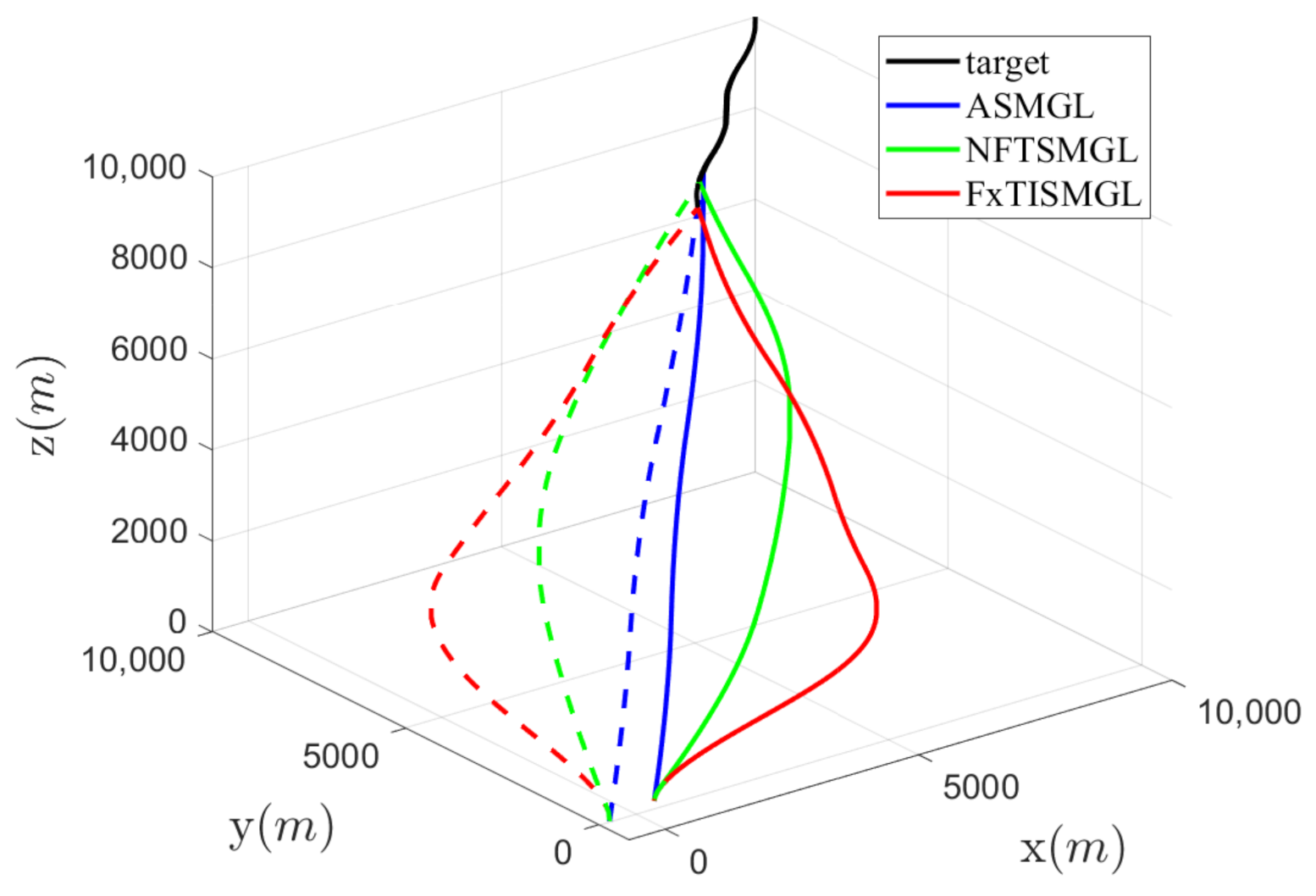
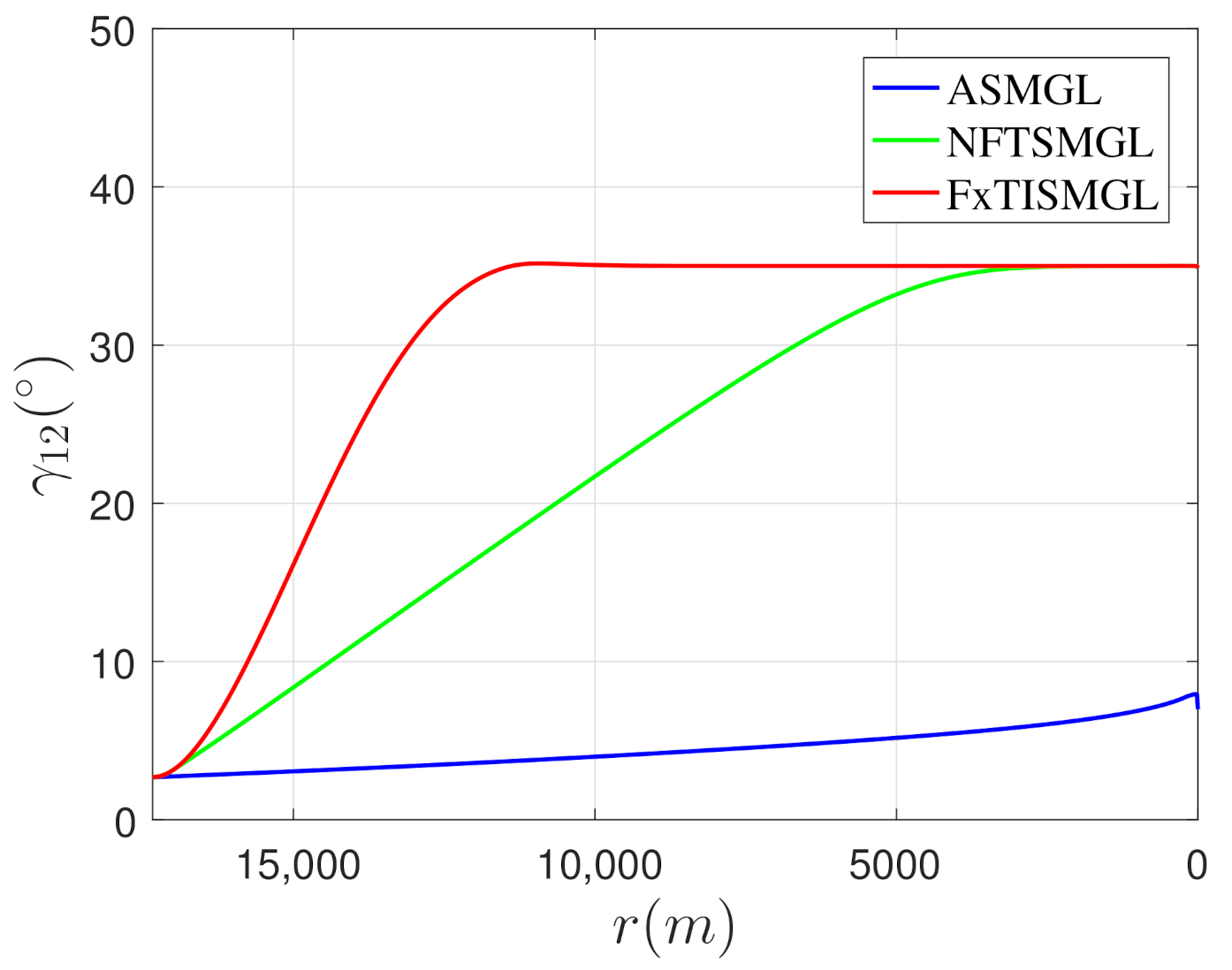
As the guidance time with different guidance is usually not the same, the curves are plotted with the missile-target range as X-axis to show the simulation results more conveniently. The complete trajectories of the missiles and the target are shown in Figure 4, and the missiles intercept the target simultaneously with small miss distances. It can be seen that as the ASMGL does not contain angle constraints, the trajectories of both missiles are rather straight. Compare with NFTSMGL, the trajectories of the missiles under the proposed FxTISMGL are more curved and more likely to perform a relative geometry during the last half of the engagement. It is shown more distinctly in Figure 5 that the coordination algorithm combined with NFTSMGL can only achieve the desired separation angle almost at the end of the interception and the ASMGL can not control the separation angle throughout the guidance, whereas the desired separation angle is imposed quickly after the interception operation started by the proposed guidance law and well maintained till the end of the guidance, which indicate that a more beneficial relative geometry is imposed for cooperative target tracking according to the analyses in Section 2.
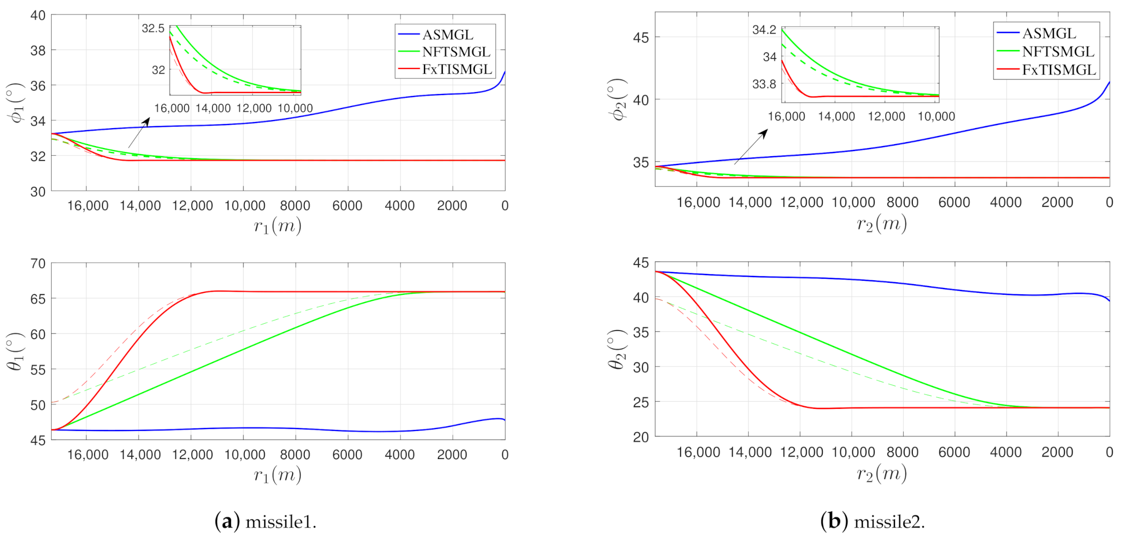
From Figure 6, it can be seen that the proposed coordination algorithm make tiny adjustments for the elevation angles ϕ of the cooperative missiles, which demonstrate the rationality of the assumption. What is more, it is clear that the propose FxTISMGL tracks the commanded LOS angles better than the NFTSMGL, and thus achieve the desired LOS angles much rapidly, especially in the azimuth channel, where both missiles are required to perform great adjustments for the azimuth angles θ .
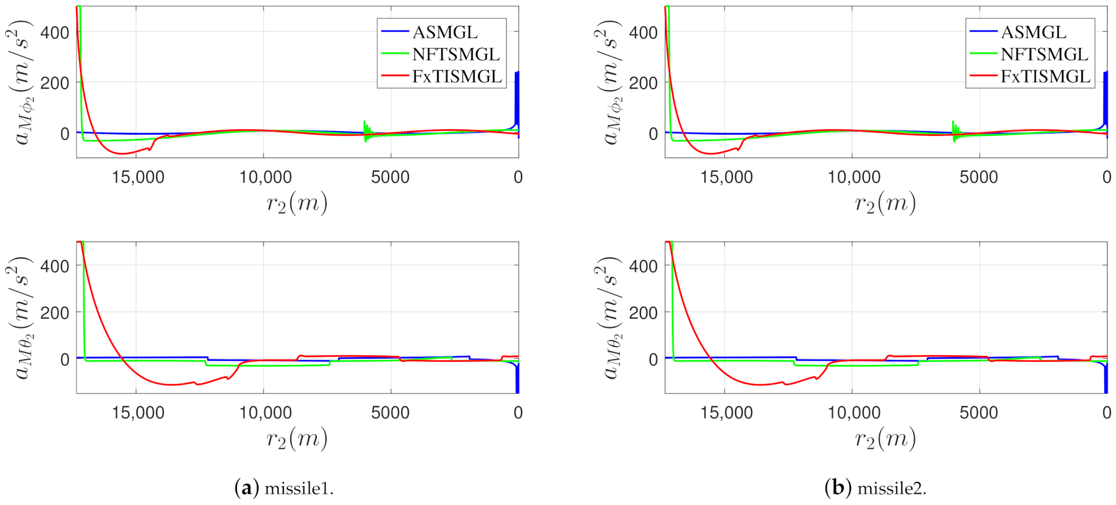
Figure 7 shows the the acceleration commands for the cooperative missiles under different guidance laws. It can be seen that the proposed FxTISMGL can provide smooth guidance commands as the other schemes, and there is no chattering phenomenon in the acceleration commands. The reason that the guidance commands of the FxTISMGL in the initial phase are larger is to achieve the faster convergence of the separation angle.
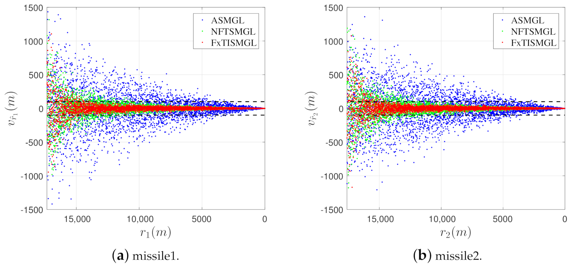
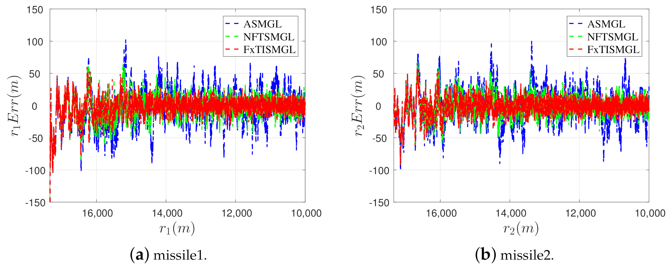
As is depicted in Figure 8, most of the guidance process, the measurement errors of the pseudo-measurement r i ^ under ASMGL may exceed 100 m, which is not satisfactory for target tracking. However, with the proposed guidance law, the measurement errors for both missiles get a great reduction compare with the other guidance laws and are all within 100 m except in the initial phase. Figure 9 shows the estimation errors of the missile-target range under different guidance laws, to show the difference more distinctly, we limit the range from interception starts to 10,000 m, it can be seen that the estimation errors of the missile-target range for both missiles under the proposed guidance law is the smallest compare with the other guidance laws, which indicate that the performances of cooperative target tracking are enhanced.
The miss distances, LOS angle convergent times (the separation angle convergent time can be viewed as the maximum of the LOS angle convergent times), the root mean squard error (RMSE) of the estimation r i ( r i > 10,000) under different guidance laws are shown in Table 2. It can be seen that the proposed FxTISMGL can provide much faster convergence rates of the LOS angles while the ASMGL can not guarantee the convergence. Furthermore, the FxTISMGL designed in this study can guarantee high-precision guidance performance: the estimation errors of the missile-target range are decreased, the performance of cooperative target tracking is enhanced and finally the miss distance is smaller.

5. Conclusions

In the paper, the problem that two cooperative missiles intercept the maneuvering target while imposing a desired relative geometry were investigated. Firstly, the 3D maneuvering target tracking model was proposed and the desired relative geometry for cooperative target tracking was discussed. Then, a two-level cooperative guidance architecture was proposed to impose the desired relative geometry. A general coordination algorithm which can decompose the separation angle between the missiles into the LOS angle constraints was proposed, the problem was solved by convex optimization methods. Thereafter, a novel 3D fixed-time convergent guidance law with LOS angle constraints was presented, which was based on integral sliding mode control and can achieve the commanded LOS angles much faster than the other guidance laws. The validity of the proposed interception guidance law was evidenced through the numerical simulations, it was shown that the cooperative interception guidance law designed in this study can enhance the performance of cooperative target tracking and achieve a high-precision target interception.
Our future work may concentrate on integrated guidance and autopilot design, considering autopilot lag. Another interesting topic is online estimation and updating of the noise covariance matrices, it seems promising to combine machine learning algorithm with the existing methods, such as the maximum likelihood based methods.

Author Contributions

Conceptualization, X.L. and W.W.; Formal analysis, P.L. and W.W.; Funding acquisition, P.L.; Methodology, X.L., Y.H. and W.W.; Software, X.L.; Validation, Y.H. and H.G.; Writing—original draft, X.L.; Writing—review and editing, H.G. and W.W. All authors have read and agreed to the published version of the manuscript.

Funding

This work was supported by Research Fund of State Key Laboratory of High Performance Computing (NUDT) under Grant 201613-02.

Institutional Review Board Statement

Not applicable.

Informed Consent Statement

Not applicable.

Conflicts of Interest

The authors declare no conflict of interest.

Abbreviations

The following abbreviations are used in this manuscript:
LOSLine of sight
WSNWireless sensor network
IRInfra-red
OGLOptimal guidance law
FxTISMGLFixed-time integral sliding mode guidance law
CKFCubature Kalman filter
ASMGLAdaptive sliding mode guidance law
NFTSMGLNonlinear finite-time sliding mode guidance law
RMSERoot mean square error

Appendix A

The filtering process of CKF can be divided into two parts: time update and measurement update. One cycle of the standard CKF algorithm involves the following steps:
(1) Time Update
Suppose that the estimation error covariance at time step k 1 is known at time k, Cholesky factorization on P k 1 k 1 yields:
P k 1 k 1 = S k 1 k 1 S k 1 k 1 T
The cubature points are calculated ( i = 1 , 2 , , m ) as follows:
X i , k 1 k 1 = S k 1 k 1 ξ i + x ^ k 1 k 1
where m = 2 n x and n x represent the number of the states.
The propagated cubature points can be obtained with the state Equation (1):
X i , k k 1 * = f X i , k 1 k 1
The predicted states and error covariance at time k are calculated by:
x ^ k k 1 = 1 m i = 1 m X i , k k 1 *
P k k 1 = 1 m i = 1 m X i , k k 1 * X i , k k 1 * T x ^ k k 1 x ^ k k 1 T + Q k 1
(2) Measurement Update
Similar to the aforementioned process, Cholesky factorization on P k k 1 :
P k k 1 = S k k 1 S k k 1 T
The cubature points are calculated ( i = 1 , 2 , , m ) as follows:
X i , k k 1 = S k k 1 ξ i + x ^ k k 1
The predicted measurements at time k are calculated by the measurement model (16):
z ^ k k 1 = 1 m i = 1 m Z i , k k 1
The innovation covariance matrix and the cross-covariance matrix can be expressed as:
P z z , k k 1 = 1 m i = 1 m Z i , k k 1 Z i , k k 1 T z ^ k k 1 z ^ k k 1 T + R k P x z , k k 1 = i = 1 m ω i X i , k k 1 Z i , k k 1 T x ^ k k 1 z ^ k k 1 T
The Kalman gain is obtained by:
W k = P x z , k k 1 P z z , k k 1 1
Finally, the updated state and corresponding error covariance at time k are estimated as follows:
x ^ k k = x ^ k k 1 + W k z k z ^ k k 1
P k k = P k k 1 W k P z z , k k 1 W k T

References

  1. Fonod, R.; Shima, T. Estimation Enhancement by Cooperatively Imposing Relative Intercept Angles. J. Guid. Control Dyn. 2017, 40, 1711–1725. [Google Scholar] [CrossRef]
  2. Parayil, A.; Ratnoo, A. Maximizing Range Observability in Bearings-Only Rendezvous Guidance. In Proceedings of the 2017 AIAA Guidance, Navigation, and Control Conference, Grapevine, TX, USA, 9–13 January 2017. [Google Scholar]
  3. Chen, T.; Xu, S. Double line-of-sight measuring relative navigation for spacecraft autonomous rendezvous. Acta Astronaut. 2010, 67, 122–134. [Google Scholar] [CrossRef]
  4. Chen, T.; Xu, S. Approach Guidance with Double-Line-of-Sight Measuring Navigation Constraint for Autonomous Rendezvous. J. Guid. Control Dyn. 2012, 34, 678–687. [Google Scholar] [CrossRef]
  5. Liu, Y.; Qi, N.; Shan, J. Cooperative Interception with Double-Line-of-Sight-Measuring. In Proceedings of the 2013 AIAA Guidance, Navigation, and Control Conference, Boston, MA, USA, 8–11 August 2011. [Google Scholar]
  6. Song, J.; Song, S.; Xu, S. Three-dimensional cooperative guidance law for multiple missiles with finite-time convergence. Aerosp. Sci. Technol. 2017, 67, 193–205. [Google Scholar] [CrossRef]
  7. Kim, B.S.; Lee, J.G. Biased PNG law for impact with angular constraint. IEEE Trans. Aerosp. Electron. Syst. AES 1998, 34, 277–288. [Google Scholar]
  8. Lee, J.; Jeon, I.; Tahk, M. Guidance law to control impact time and angle. IEEE Trans. Aerosp. Electron. Syst. 2007, 43, 301–310. [Google Scholar]
  9. Zhang, Y.; Ma, G.; Liu, A. Guidance law with impact time and impact angle constraints. Chin. J. Aeronaut. 2013, 26, 960–966. [Google Scholar] [CrossRef] [Green Version]
  10. Ratnoo, A.; Ghose, D. State-Dependent Riccati-Equation-Based Guidance Law for Impact-Angle-Constrained Trajectories. J. Guid. Control Dyn. 2009, 32, 320–326. [Google Scholar] [CrossRef]
  11. Lee, Y.I.; Kim, S.H.; Tahk, M.J. Optimality of Linear Time-Varying Guidance for Impact Angle Control. IEEE Trans. Aerosp. Electron. Syst. 2012, 48, 2802–2817. [Google Scholar] [CrossRef]
  12. Zhang, W.; Xia, Q.; Li, W. Novel second-order sliding mode guidance law with an impact angle constraint that considers autopilot lag for intercepting manoeuvering targets. Aeronaut. J. 2020, 124, 1350–1370. [Google Scholar] [CrossRef]
  13. Lin, D.; Ji, Y.; Wang, W.; Wang, Y.; Wang, H.; Zhang, F. Three-dimensional impact angle-constrained adaptive guidance law considering autopilot lag and input saturation. Int. J. Robust Nonlinear Control 2020, 30, 3653–3671. [Google Scholar] [CrossRef]
  14. Zuo, Z.; Tie, L. A new class of finite-time nonlinear consensus protocols for multi-agent systems. Int. J. Control 2014, 87, 363–370. [Google Scholar] [CrossRef]
  15. Huang, Y.; Jia, Y. Fixed-time consensus tracking control for second-order multi-agent systems with bounded input uncertainties via NFFTSM. IET Control Theory Appl. 2017, 11, 2900–2909. [Google Scholar] [CrossRef]
  16. Li, G.; Wu, Y.; Xu, P. Adaptive Fault-tolerant Cooperative Guidance Law for Simultaneous Arrival. Aerosp. Sci. Technol. 2018, 82–83, 243–251. [Google Scholar] [CrossRef]
  17. Shaferman, V.; Shima, T. Cooperative Optimal Guidance Laws for Imposing a Relative Intercept Angle. J. Guid. Control Dyn. 2015, 38, 1395–1408. [Google Scholar] [CrossRef]
  18. Shiyu, Z.; Rui, Z. Cooperative Guidance for Multimissile Salvo Attack. Chin. J. Aeronaut. 2008, 21, 533–539. [Google Scholar] [CrossRef] [Green Version]
  19. Yang, C.D.; Yang, C.C. Analytical solution of generalized three-dimensional proportional navigation. J. Guid. Control. Dyn. 1996, 19, 721–724. [Google Scholar] [CrossRef]
  20. Yang, C.D.; Yang, C.C. Analytical solution of 3D true proportional navigation. IEEE Trans. Aerosp. Electron. Syst. 1996, 32, 1509–1522. [Google Scholar] [CrossRef]
  21. Zarchan, P. Tactical and Strategic Missile Guidance, 6th ed.; AIAA: Reston, VA, USA, 2012; pp. 187–211. [Google Scholar]
  22. Yuen, K.V.; Kuok, S.C. Online updating and uncertainty quantification using nonstationary output-only measurement. Mech. Syst. Signal Process. 2015, 66. [Google Scholar] [CrossRef]
  23. Kontoroupi, T.; Smyth, A. Online Noise Identification for Joint State and Parameter Estimation of Nonlinear Systems. ASCE-ASME J. Risk Uncertain. Eng. Syst. Part A Civ. Eng. 2015, 2, B4015006. [Google Scholar] [CrossRef]
  24. Hu, G.; Gao, B.; Zhong, Y.; Gu, C. Unscented Kalman Filter with Process Noise Covariance Estimation for Vehicular INS/GPS Integration System. Inf. Fusion 2020, 64. [Google Scholar] [CrossRef]
  25. Li, S.; Ma, M.; Tang, X.; Huang, Y.; Wang, F. Maximum Likelihood Criterion based Adaptive CKF Algorithm for Integrated Navigation. In Proceedings of the 11th China Satellite Navigation Conference, Chengdu, China, 23–25 November 2020. [Google Scholar]
  26. Arasaratnam, I.; Haykin, S. Cubature Kalman Filters. IEEE Trans. Autom. Control 2009, 54, 1254–1269. [Google Scholar] [CrossRef] [Green Version]
  27. Zhou, D.; Sun, S.; Teo, K. Guidance Laws with Finite Time Convergence. J. Guid. Control Dyn. 2009, 32. [Google Scholar] [CrossRef]
  28. Hong, Y. Finite-Time Stabilization and Stabilizability of a Class of Nonlinear Systems. Syst. Control Lett. 2002, 46, 231–236. [Google Scholar] [CrossRef]
  29. Polyakov, A. Nonlinear Feedback Design for Fixed-Time Stabilization of Linear Control Systems. IEEE Trans. Autom. Control 2012, 57, 2106–2110. [Google Scholar] [CrossRef] [Green Version]
  30. Parsegov, S.; Polyakov, A.; Shcherbakov, P. Fixed-time consensus algorithm for multi-agent systems with integrator dynamics. IFAC Proc. Vol. 2013, 46, 110–115. [Google Scholar] [CrossRef] [Green Version]
  31. Zuo, Z. Non-singular fixed-time terminal sliding mode control of non-linear systems. IET Control Theory Appl. 2015, 9, 545–552. [Google Scholar] [CrossRef]
  32. Tian, B.; Lu, H.; Zuo, Z.; Wang, H. Fixed-time stabilization of high-order integrator systems with mismatched disturbances. Nonlinear Dyn. 2018, 94, 2889–2899. [Google Scholar] [CrossRef]
  33. Tian, B.; Lu, H.; Zuo, Z.; Yang, W. Fixed-Time Leader-Follower Output Feedback Consensus for Second-Order Multiagent Systems. IEEE Trans. Cybern. 2018, 49, 1545–1550. [Google Scholar] [CrossRef]
  34. Jeon, I.S.; Lee, J.I.; Tahk, M.J. Homing Guidance Law for Cooperative Attack of Multiple Missiles. J. Guid. Control Dyn. 2010, 33, 275–280. [Google Scholar] [CrossRef]
  35. Zhou, D.; Mu, C.; Xu, W. Adaptive Sliding-Mode Guidance of a Homing Missile. J. Guid. Control Dyn. 1999, 22, 589–594. [Google Scholar] [CrossRef]
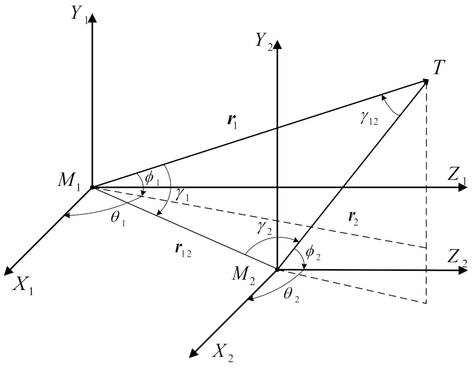
Figure 1. Three-dimensional engagement geometry.
Aerospace 08 00006 g001
Figure 2. Curve of m a x ( σ r ^ ) with γ i j given r i j = 10 km, σ γ = 0.3 .
Aerospace 08 00006 g002
Figure 3. Two-level dynamic cooperative guidance architecture for relative geometry imposing.
Aerospace 08 00006 g003
Figure 4. Three-dimensional interception trajectories under different guidance laws. Solid line: missile1, dashed line: missile2.
Aerospace 08 00006 g004
Figure 5. The separation angle between the cooperative missiles.
Aerospace 08 00006 g005
Figure 6. The curves of the LOS angles. Solid line: actual value, dashed line: commanded value.
Aerospace 08 00006 g006
Figure 7. The curves of the acceleration commands.
Aerospace 08 00006 g007
Figure 8. The measurement errors of the missile-target range. Black dashed line: 100 m.
Aerospace 08 00006 g008
Figure 9. The estimation errors of the missile-target range.
Aerospace 08 00006 g009
Table 1. Initial Conditions.
ModeMissile-1Missile-2Target
position
(m)
x0−50010,000
y−500010,000
z500010,000
velocity
(m/s)
x30030080
y300300−120
z30030040
Table 2. Initial Conditions.
Guidance LawMiss Distance (m)Convergent Time of ϕ (s)Convergent Time of θ (s)RMSE of r (m)
ASMGLMissile10.431230.2804
Missile20.715329.3604
NFTSMGLMissile10.226214.361025.913020.2227
Missile20.384613.196024.493019.4695
FXISMGLMissile10.10154.480010.505016.5124
Missile20.17383.883010.337016.1186
Publisher’s Note: MDPI stays neutral with regard to jurisdictional claims in published maps and institutional affiliations.