1. Introduction
The stall of an axial compressor is characterized by an abrupt change in the flow pattern passing through the compressor, altering its pressure rise capability and leading to flow reversal. This phenomenon, appearing at low mass flow rates, is very dangerous and it has to be avoided as it reduces the engine thrust and can severely damage the compressor.
Consequently, it is necessary to restrict the compressor operating range, avoiding working points characterized by low mass flow rates, but high pressure ratio, due to their excessive proximity to the stability limit line. Several methods to avoid and delay stall inception have been developed in order to increase compressor stall margin. These techniques can be active or passive and their main purpose is to improve the machine stability without affecting the performance at the design point.
Active control methods modify the compressor flow using different types of actuators and feedback control systems. A pulsed air injection is implemented in order to delay the rotating stall mechanism in low speed axial flow compressor. The system is managed by an algorithm which determines the magnitude and phase of the first mode of rotating stall and controls the injection of air in the front of the rotor face [
1].
On the other hand, the aim of passive methods is to change the flow pattern, introducing compressor geometry modifications in order to achieve a stall margin improvement without any external input. Passive methods are simpler, cheaper, lighter and safer compared to the active ones due to the lack of a control system. Different types of passive controls have been explored so far. As the tip leakage vortex interaction with the blade tip clearance flow produces the most critical region of low momentum fluid [
2], several forms of endwall treatments were studied in order to modify the flow field near the compressor case. The first reported work related to compressor stability enhancements was a patent by Wilde [
3], who investigated casing treatments. As reported by Hathaway [
4], there are mainly two types of casing treatments: groove-based or slot-based. In general, the slot-based casing treatment generates the highest stall margin. However, greater efficiency losses were recorded for this configuration compared to the groove-based method. For this reason, groove-based casing treatments are usually preferred.
Grooves are circumferentially continuous cavities cut into the endwall above the rotor tip that modify locally the flow field changing and delaying the stall inception process. Groove-based casing treatments were investigated for the first time by Moore et al. [
5] who analysed several groove configurations stating their effectiveness in improving stall margin of an axial compressor. The way in which the grooves interact with the local flow field in the tip gap is not fully understood. Due to the lack of knowledge about this physical phenomenon, there is no agreement in the literature about how they work, what their optimal shape should be and where they should be located.
Shabbir and Adamczyk [
6] performed numerical simulations in order to understand the flow mechanism that provides the increase in the stall margin. They explained that, for the grooved casing, the net axial force due to the radial transport of axial momentum across the groove and the net axial shear force are equivalent to the net axial pressure force in the tip gap. Further findings and quantitative explanations of this complex flow mechanism were carried out by Legras et al. [
7].
Haixin et al. [
8] showed the influence of the tip clearance depth to the stall process: when the tip gap is small, the stall originates from the trailing edge flow separation; instead, when it is large, the stall starts from the breakdown of the tip leakage vortex. Depending on the different stall mechanism, a mid-chord groove is more effective for the small tip gap configuration, while a leading edge groove works better for a large tip gap configuration.
The shape and the depth of grooves play an important role in the stall margin improvement. Experimental and numerical investigations carried out by Muller et al. [
9] highlighted a strong increment in stall margin and total pressure ratio as the depth of the grooves increases. Furthermore, an efficiency loss is registered for these configurations compared to the smooth wall. Finally, independently from the groove depth, a wider covered part of the rotor chord is to be preferred to delay stall inception. Houghton and Day [
10] conducted a parametric study of the groove location into two different compressors. The results demonstrated two optimal axial positions where the stall margin is maximized: one near the leading edge (10% chord), the other near 50% chord. In the first case, the tip leakage vortex direction is changed by the presence of the groove, leading to a considerable loss of efficiency. According to their results, a stall margin improvement is gained only if spike-type stall inception occurs before and after the grooves are added.
Many numerical studies were performed considering the NASA Rotor 37 transonic axial compressor. Huang et al. [
11] showed the capability of the case treatment to suppress separation of the flow at the trailing edge, delaying the blade tip leakage vortex breakdown to a higher back pressure. The effect of grooves located from 15% to 40% of the chord is a change in the leading edge blade tip leakage vortex trajectory, while grooves from 45% to 85% are able to suppress the trailing edge separation. Sakuma et al. [
12] investigated the effect of single circumferentially grooved casing treatment on the stall margin, taking into account deep and shallow grooves. The maximum improvement in stall margin was achieved with a deep groove located at 20% chord downstream from the leading edge. Mirzabozorg et al. [
13] analysed circumferential shallow grooves with a constant depth (three times the rotor tip clearance), but different width and axial location. According to the computational analysis, the highest stall margin was achieved at a 40% chord axial location with a 40% chord wide groove.
Other CFD analysis demonstrated a higher stall margin improvement using multiple circumferential grooves. In particular, Choi et al. [
14] performed a design optimization of casing grooves implementing the radial basis neural network method and achieving a maximum of 7.3% stall margin improvement in a five-groove configuration. Another design optimization research was carried out by Quin et al. [
15] using the novel mesh technique of the zipper layer. It was found that six optimized shape grooves are able to enhance the stall margin of 0.73% without reducing the peak efficiency value.
The variety of configurations studied and found in the literature about circumferential grooves highlights the design complexity of an effective casing treatment characterized by a high stall margin improvement and a minimum loss of efficiency compared to the smooth wall case (without grooves). This difficulty is given by the big amount of parameters such as the groove shape, depth, width, and axial location that influence this phenomenon, together with a not well understood modification of the flow field at the near-stall point, due to the presence of the groove. This underlines the need for further experimental and computational studies about circumferential casing grooves, aimed at investigating new shapes and configurations.
The purpose of this paper is to analyse the effect of new T-shape grooves on the stability enhancement of the NASA Rotor 37 axial transonic compressor. A computational fluid dynamic approach is used to investigate the stall margin improvement and the efficiency losses. First, a model validation of the smooth wall case is performed by comparing numerical results to experimental data available in the literature to ensure the reliability of the code and the model. Then, a rectangular groove configuration named as the baseline is chosen to investigate in detail the flow field near the blade tip, focusing on the mechanism of stall delay. Finally, the performances of the new T-shape grooves are evaluated and compared to the baseline and to the smooth wall cases.
2. Circumferential Casing Grooves
The performance of a single groove with a fixed axial location cut into the casing above the rotor blade tip is examined in this study. The literature contains many papers which take into account different groove shapes and positions over the rotor blade tip. The independent parameters used to analyse this problem are width, depth, and axial location, and the most common shape is the rectangular one. First, a simple rectangular groove configuration found in the literature is selected as a baseline to investigate the casing treatment effect on the near blade tip flow field and to calculate the stall margin improvement. Then, new T-shape grooves are analysed in order to examine whether better performances can be achieved in terms of stall margin improvement and efficiency variation.
The rectangular configuration, here called the baseline, corresponds to the one presented by Sakuma et al. [
12]. They demonstrated that this specific combination of width, depth, and axial location for a single groove is the most effective, achieving a stall margin of almost 3.5%, one of the highest reported in the literature. For this reason, the aforementioned geometry was chosen as a starting point and a baseline reference to investigate the effectiveness of the new T-shape grooves.
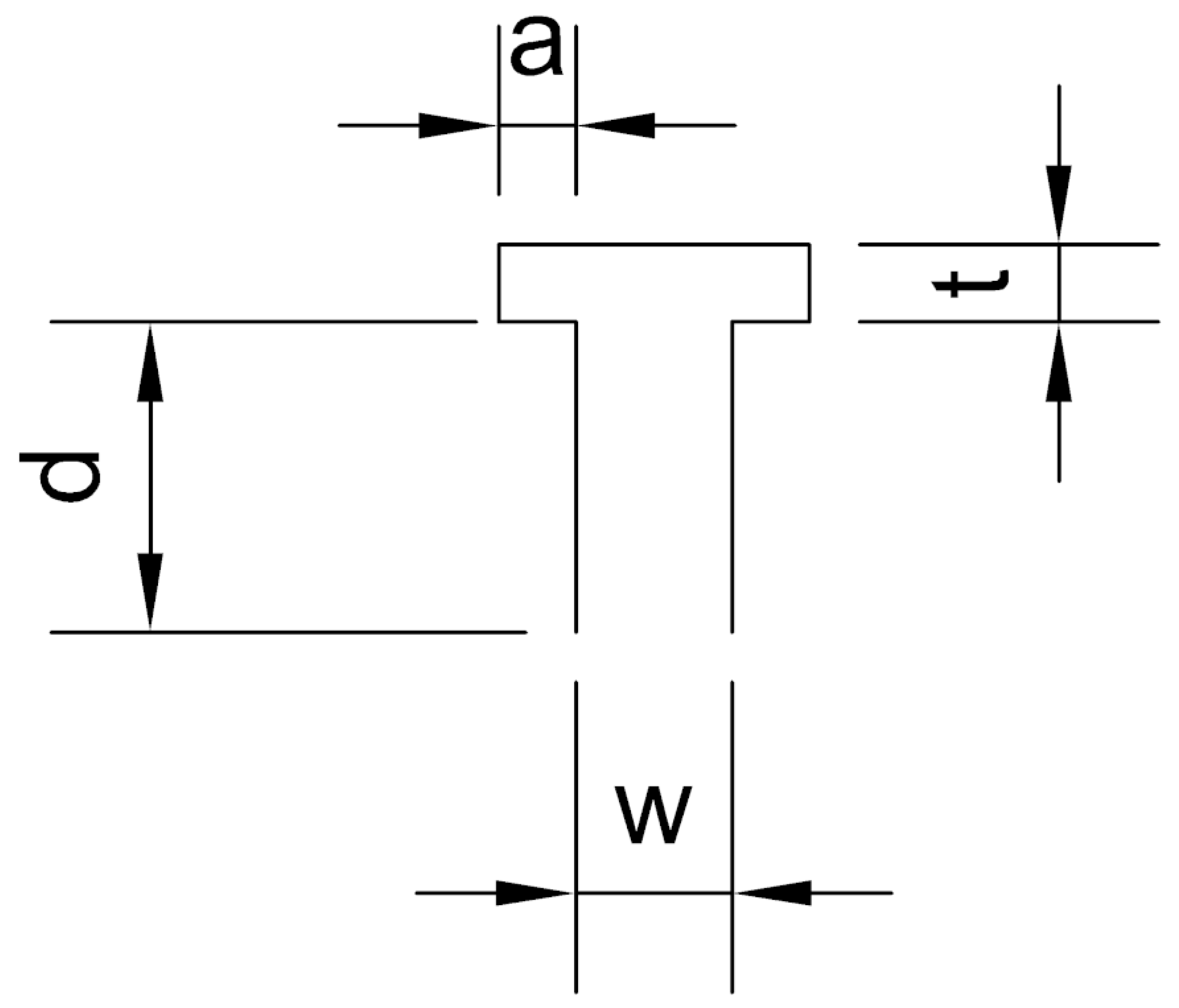
Table 1 and
Figure 1 show the baseline geometry. Axial location refers to the position of the groove corner closer to the leading edge, and it is calculated as a percentage of the blade tip axial chord. The ANSYS Design Modeler was used to create the groove geometry.
Since a single rectangular groove has been exhaustively studied in the literature, new groove shapes are investigated in this paper. A particular T-shape was chosen: it is thought that the upper horizontal arm of the “T” could act as a plenum, reducing instabilities that lead to stall inception. Therefore, this geometry can probably produce a stall margin improvement.
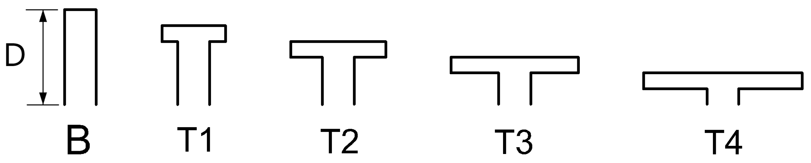
First, four T-shape configurations were investigated: T1, T2, T3, and T4.
Table 2 and
Figure 2 and
Figure 3 show their geometric parameters compared to the baseline (B).
The four groove configurations are similar in that the cross section area is constant and, therefore, the volume of the different grooves is equal to that of the baseline. Furthermore, all four configurations share the same width
w and the same value of
t, while the groove height is gradually decreased by 1/6 of the baseline depth. It has been demonstrated by many papers [
12,
14] that the groove depth plays an important role in the stall margin improvement: the deeper the grooves are, the wider the extension of the compressor operating range is. However, deep grooves need a thicker casing, introducing additional weight to the engine: this should be avoided in aerospace applications.
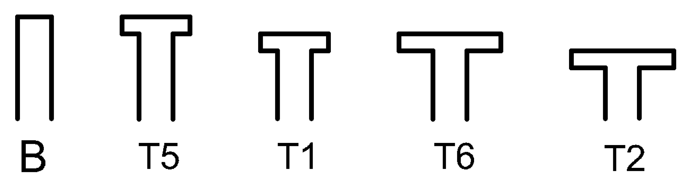
Finally, two other configurations T5 and T6 were investigated. Their geometry is shown in
Figure 4 compared to the baseline and T1, T2 grooves. Different parameters such as the groove depth and the length of the horizontal arm
a are changed, leading to a volume increment of 16,6%. This will allow interesting comparisons, investigating how the dimensions of the upper plenum influence the stall margin parameter.
3. Numerical Methods
3.1. NASA Rotor 37 Specifications
The axial transonic compressor NASA rotor 37 was selected as a test case to study the effect of groove-based casing treatment. It was originally designed and tested by Reid and Moore [
16] as a low ratio inlet stage for an eight-stage core compressor with a 20:1 pressure ratio. It was then retested in isolation by Suder [
17] to avoid the interaction effects generated by the presence of an upstream inlet guide vane or downstream stator blade row. Thanks to the big amount of experimental data and studies available in the literature, this rotor geometry became the test case for CFD code validation and for the investigation of new stability enhancements such as casing treatment. For this reason, NASA rotor 37 geometry was chosen in this paper and the experimental data collected by Suder [
17] were used to perform the code validation.
Following the work by Suder [
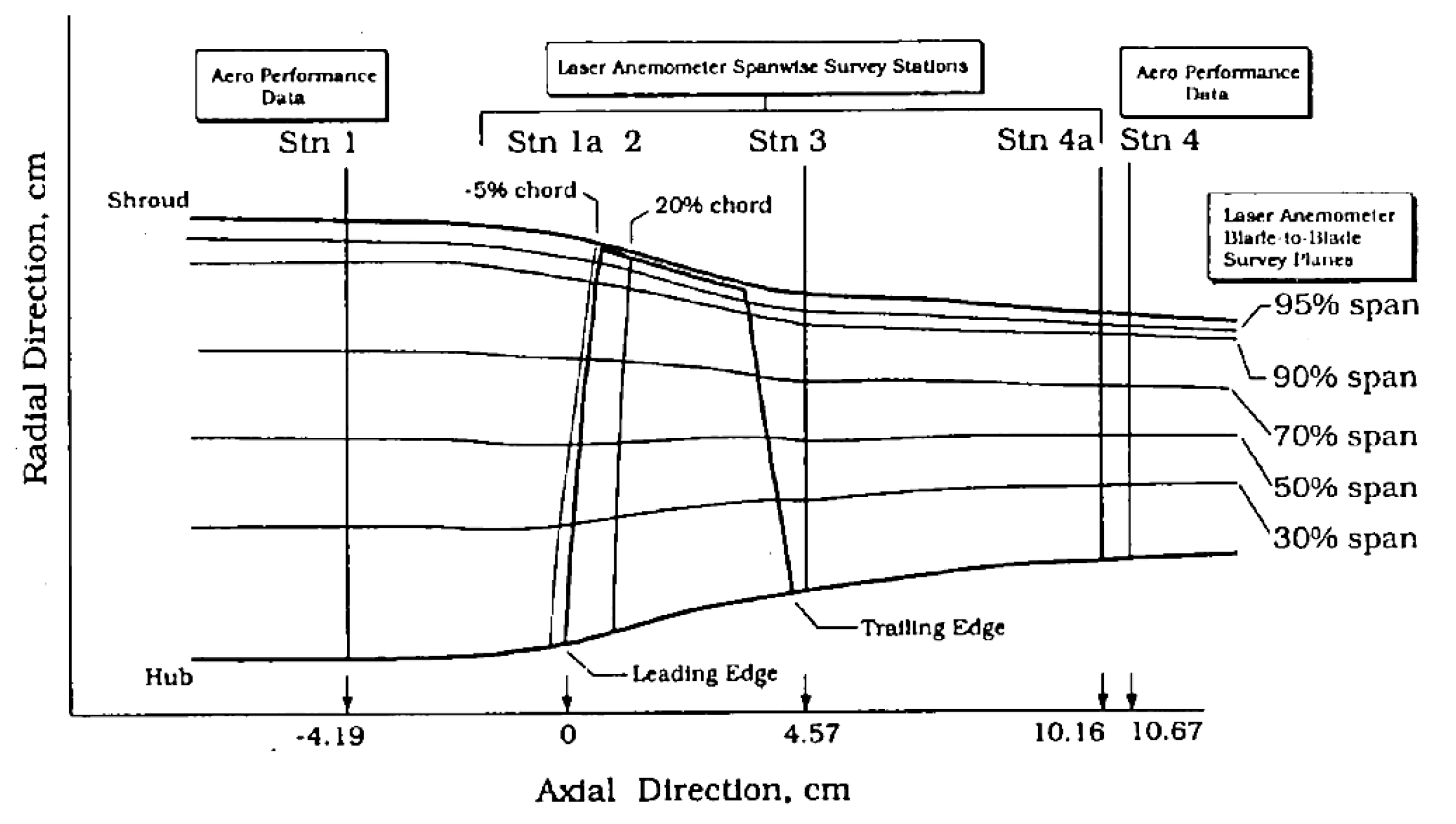
17], the compressor is composed of 36 rotor blades operating at a rotational speed of 17188.7 rpm. As reported in
Table 3, the design point performance is characterized by a mass flow rate of 20.19 kg/s achieving a 2.016 pressure ratio and a 87.7% adiabatic efficiency. The tip clearance is 0.0356 cm (0.47% span), and the near stall point is experimentally determined at 0.925 of the chocking mass flow rate (20.93 kg/s). Referring to
Figure 5, the total inlet pressure and total inlet temperature at station 1 are, respectively, 1 atm and 288.15 K.
3.2. Computational Domain
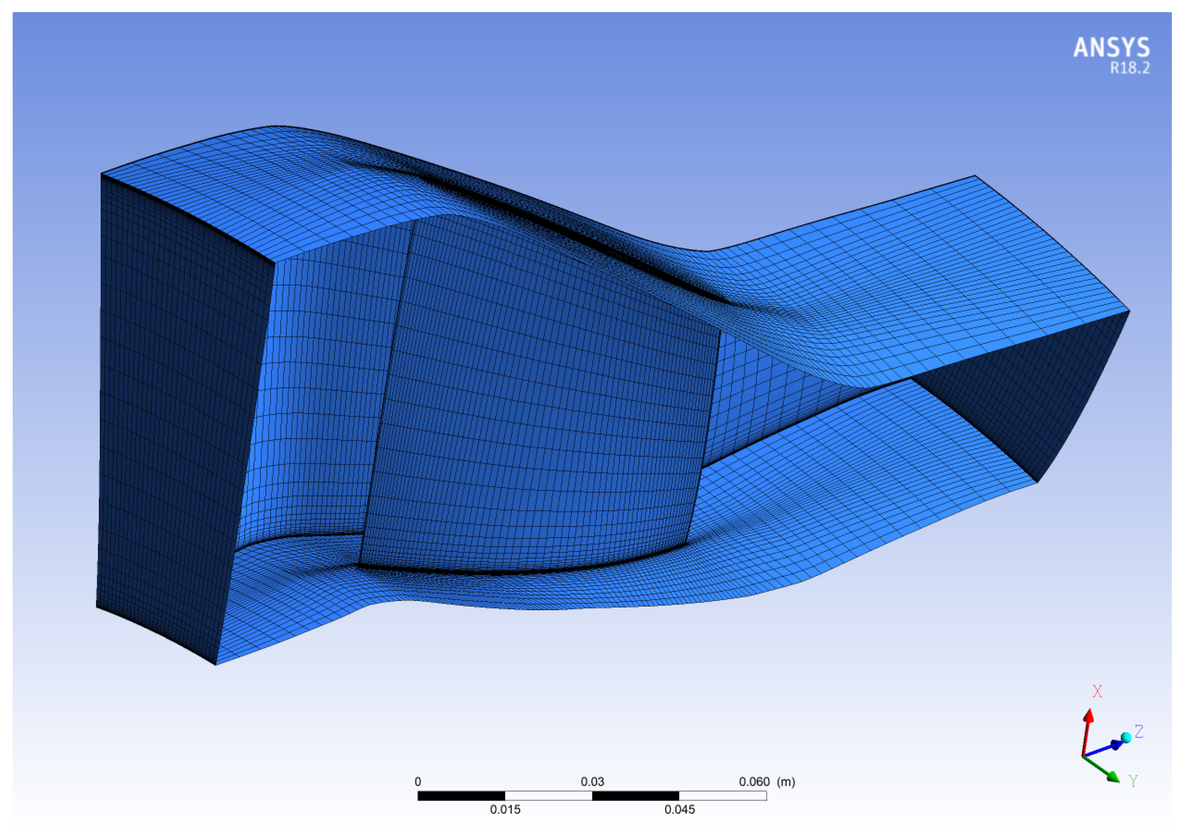
CFD analysis was performed through a three-dimensional RANS approach. The commercial code ANSYS-CFX 18.2 was used to carry out the analysis. The computational domain considered is composed of a single passage of the axial compressor, and it was created using Turbo-Grid: the assumption of a periodic flow field between two blades in the rotational direction is made. Limiting the computational domain to a single passage allows the use of a finer mesh able to resolve the flow in critical regions and, at the same time, maintaining a relatively low CPU cost.
The computational mesh created using Turbo-Grid 17.1 and chosen for the analysis is showed in
Figure 6.
The traditional topology with control points was applied to the passage domain, creating a structured mesh using an H-Grid method. Near the blade surface, an O-type grid was built with a width factor of 0.5 and 17 elements in order to precisely control the mesh distribution in that region. For the mesh portion over the blade tip, an H-Grid not matching topology was set.
The main passage consists of 86 elements alongside the blade surface and 24 in the circumferential direction. The near wall element size was specified by keeping a
and a maximum expansion rate of 1.3 in order to carefully capture the wall shear stress near the blade, the shroud and the hub. A total of 60 elements were spread over the blade span and the tip gap was filled with 20 elements, above the minimum recommended number by Van Zante et al. [
19].
As proposed in many CFD analysis of NASA Rotor 37 [
13,
14], the inlet and the outlet were trimmed at a stream-wise location of −4.19 cm and 10.67 cm respectively, referring to the leading edge position (
Figure 5).
Finally, the total number of mesh elements is 520,000. The dimensions and features of the computational domain are comparable with those described in other papers by Choi et al. [
14] and Mirzabozorg et al. [
13] that considered 480,000 and 471,154 elements, respectively.
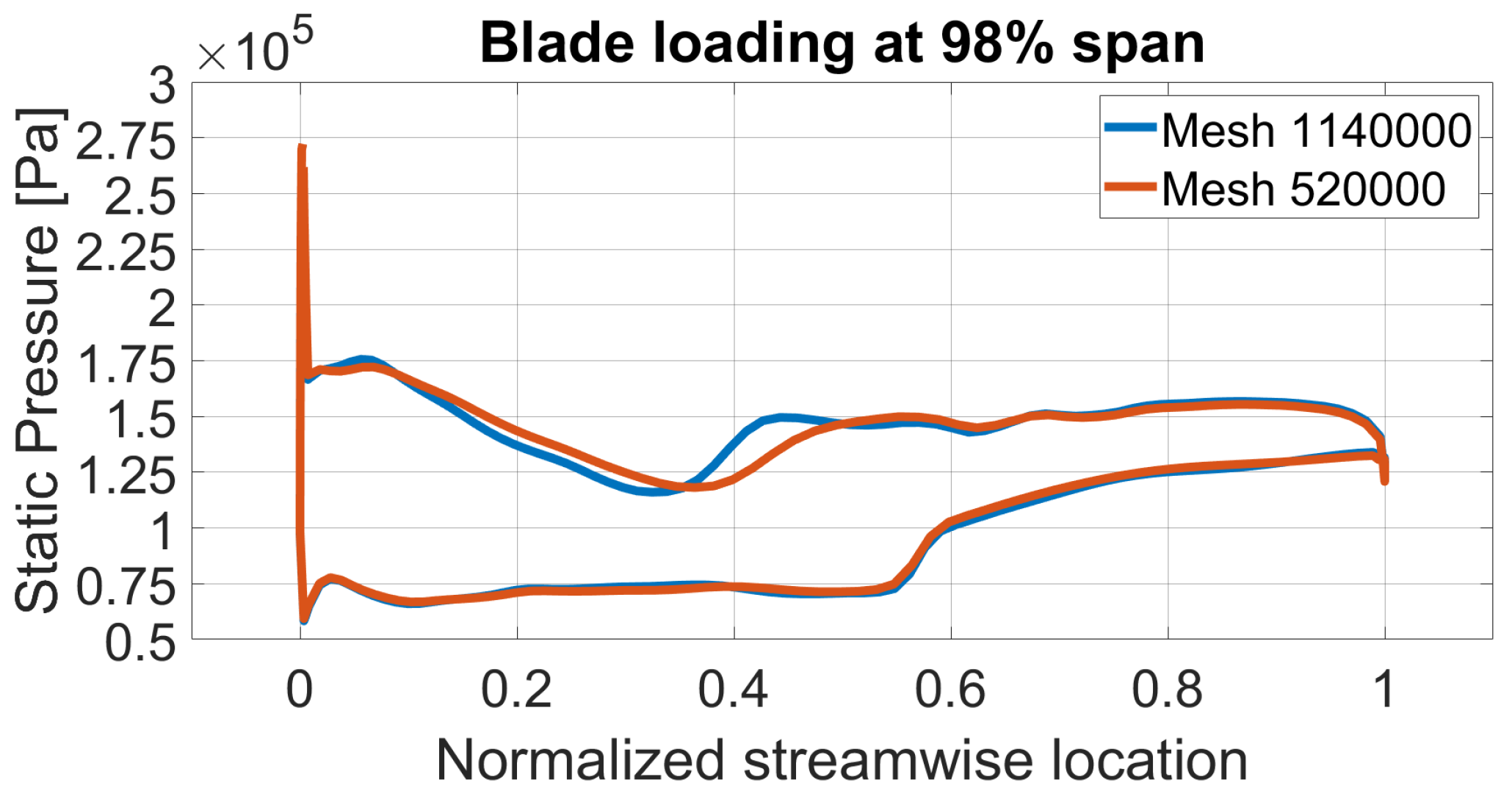
A mesh independence study was carried out to justify the use of this particular mesh, doubling the number of elements to 1,140,000.
Figure 7 shows the blade loading at 20% span: the differences between the two lines are small and the static pressure profiles are almost coincident. Therefore, considering the little discrepancies and the gain in terms of computational time saving, the 520,000 mesh was selected to perform this study.
Since it was not possible to create a single structured mesh including both the blade and the groove domains using Turbo-Grid, a separate mesh for the casing treatment was generated using ICEM CFD. Then, an interface between the two meshes was set in CFX-Pre in order to glue them as a single fluid domain.
First, a structured mesh was created for the baseline including 50 uniform elements in the circumferential direction, and 30 and 40 in the groove width and depth, respectively. The near-wall first node distance was kept equal to
m in order to obtain a
and the near-wall expansion rate was set to 1.3. The mesh dimensions are similar to those presented by Choi et al. [
14], where the grid was constructed with
elements.
T-shape groove meshes were generated using the same method, keeping equal values for the near-wall parameters ( and expansion rate). All the configurations share the same number and distribution of elements at the interface with the passage mesh in order to not modify the interaction between the two domains. This way, comparisons among different configurations are more reliable and reasonable. In addition, the number of elements along the thickness of the horizontal arm (t) was fixed to 20 for all the grooves.
3.3. Computational Setup
ANSYS CFX 18.2 uses a pressure based, coupled implicit algorithm to solve Reynolds-Averaged-Navier–Stokes (RANS) equations. Steady-state simulations were conducted to investigate the compressor performance.
The rotor domain is set as rotating at a speed of 1800 rad/s, and the air is considered as an ideal gas. The total pressure (1 atm) and the total temperature (288.15 K) were set at the inlet, while an averaged static pressure condition is applied over the whole outlet. A rotational periodicity is set as a boundary condition for the sideward surfaces of the passage domain using a 1:1 mesh connection between the two sides. The blade, the hub, and the shroud are considered as no slip smooth adiabatic walls in a rotating (blade and hub) or counter-rotating (shroud) frame type.
The turbulence model considered in this analysis is the k-
based Shear-Stress-Transport (SST). It was designed to give highly accurate predictions of flow separation under adverse pressure gradients, combining the advantages of the k-
formulation near the wall and k-
in the bulk domain [
20]. In addition, a smooth transition between the two models is ensured by a blending function. For these features, the SST model is recommended for accurate boundary layer simulations for turbomachinery.
A logarithmic wall function can be implemented to approximate the velocity distribution near the wall, using empirical formulas without resolving the boundary layer. Therefore, a relatively coarse mesh can be used to capture the shear layer near the wall, saving computational time. On the other hand, a Low-Reynolds-Number method should be implemented to describe in detail the boundary layer profile. In particular, a good numerical resolution is obtained only with a fine mesh near the wall, able to capture the rapid variation in variables. This leads to the need of higher computational resources and CPU time. To obtain the benefits of both approaches, an automatic near-wall treatment is used to model the flow in the near-wall region: for k- based models, this allows for a smooth transition from a low Reynolds number to a wall function formulation.
However, the SST model exaggerates the flow separation from smooth surfaces under the influence of adverse gradients, as observed in all RANS models [
20]. In particular, they underpredict the turbulent stresses in the separating shear layer, leading to overly large separation regions. The problem can be solved using a Reattachment Modification (RM) model, which improves turbulence levels in the shear layer close to the walls, enhancing the SST model [
21]. Therefore, the turbulence model chosen for the simulations is a k-
based SST with a Reattachment Modification model.
Modeling the near wall region in this way does not require a highly refined grid resolution (
) and, therefore, a
was guaranteed over the all domain walls, as recommended in some papers [
14]. For the inlet boundary condition, a medium turbulence (5%) and a length scale equal to the passage domain height were set.
The advection scheme was set to high resolution: with this option, the blend factor value vary throughout the domain, achieving the value of 1 (second-order accuracy) in regions with low variable gradients and 0 (first-order accuracy) in areas where the gradients change sharply [
20]. As the results obtained with the high resolution scheme showed little differences, a first order turbulence scheme was chosen for the robust performance of the CFX-Solver. The simulations were executed using a local parallel setup of a 16 core computer, reducing the solution time from six hours (single core) to 1.5 hours (16 parallel cores).
The groove domain was treated as stationary. In order to transfer the flow field information between the two meshes, a GGI frozen rotor interface available in CFX-Pre was used. This interface option is suitable for simulating adjacent rotating and stationary domains, assuming a fixed relative position between them throughout the calculation. Cevik [
22] used the same setup to investigate the effect of multiple sawtooth grooves.
4. Methodology
Changing the static back pressure at the outlet, a precise mass flow rate was established in the machine, obtaining different rotor performances in terms of pressure ratio, total temperature ratio, and adiabatic efficiency. Using this methodology, the entire working range from stall to the choking point was investigated. Particular attention was paid to analyse the stall inception point: at a certain high static pressure at the outlet, a constant and monotone reduction was observed in the mass flow rate monitor as the iteration number increased. Further exit static pressure increments led to a numerical mass flow rate drop to zero, stating that the stall point was achieved. In order to discriminate the precise mass flow rate at which the stall inception occurs, the following convergence criteria, similar to those proposed by Haixin et al. [
8], were adopted:
- (i)
The inlet mass flow rate variation is less than 0.005 kg/s for 200 steps.
- (ii)
The difference between inlet and outlet mass flow rate is less than 0.5%.
- (iii)
At that time, the adiabatic efficiency variation is less than 0.03% per 100 steps.
Near the stall point, the static pressure at the outlet was increased smoothly with a resolution of 100 Pa: the last converged point following the previous criteria was considered as the compressor stall point. A step of 100 Pa was adopted also by Quin et al. [
15] in their simulations. The same pressure resolution was adopted to investigate the near-peak efficiency point.
Once the entire rotor working line was drawn, stall margin was calculated as follows [
11]:
where
PR is the pressure ratio,
m is the mass flow rate and
peak and
stall refer to the peak efficiency and the near stall point, respectively.
To investigate the effects of the groove on the stall margin and the peak efficiency,
and
were calculated as follows [
13]:
They represent the stall margin improvement and peak adiabatic efficiency variation of the grooved wall case (GW) compared to the smooth wall case (SW).
5. Validation
Comparisons between experimental and computational data were carried out to perform a code validation. Experimental data available in the literature for the NASA Rotor 37 are mainly provided by Suder [
17] and Dunham [
18].
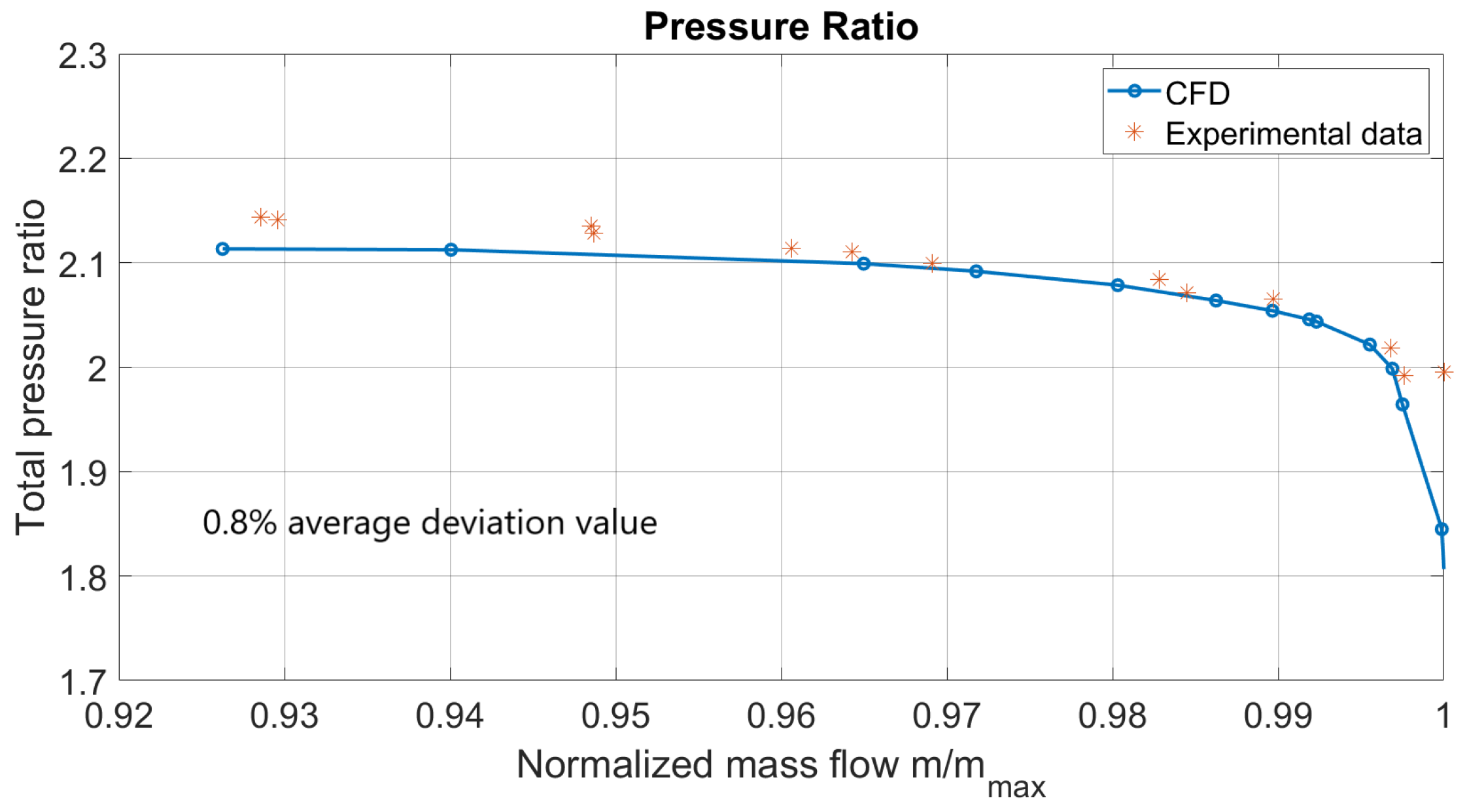
Figure 8 highlights a comparison between the computational results and experimental data [
18]. The CFD analysis is able to predict the compressor performance accurately, generating results which are very close to the experimental data in terms of tendency and absolute values.
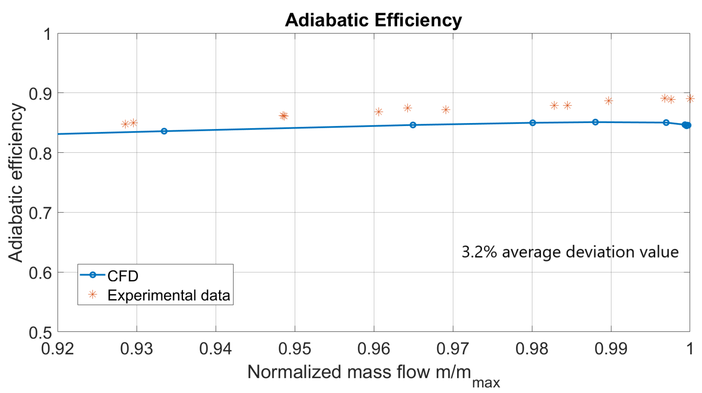
On the other hand,
Figure 9 shows an underestimation of adiabatic efficiency: from this point of view, the code fails to precisely represent the rotor operating conditions. Other papers available in the literature reported this consistent deviation [
13,
14], and the reasons are still unknown [
15]. Despite the underestimation, the efficiency trend agrees with experimental data and the absolute values are comparable to those obtained in other papers.
The simulations predicted a near-stall normalized mass flow rate of 0.926 (
), which is very close to the 0.925 provided by experimental analysis [
17].
The peak efficiency condition corresponding to 98% of the choking mass flow was chosen to evaluate span-wise distributions from the hub to the shroud of pressure ratio, temperature ratio, and adiabatic efficiency. The experimental data are compared to computational profiles obtained using CFX-Post as shown in
Figure 10a–c.
It can be stated that CFD simulations are able to precisely predict span-wise distributions, showing slight differences in terms of trends and discrepancies in the absolute values. The pressure ratio profile is the most accurate, while the adiabatic efficiency distribution displays the greatest deviation. However, the tendency is in agreement with the underestimation of the adiabatic efficiency found in the performance map. The same discrepancies were registered by Ameri [
23] and Boretti [
24] using different computational codes.
Results presented so far highlight the accuracy and the reliability of the computational model. Some deviations from experimental data exist, but they are consistent with those widely reported in the literature.
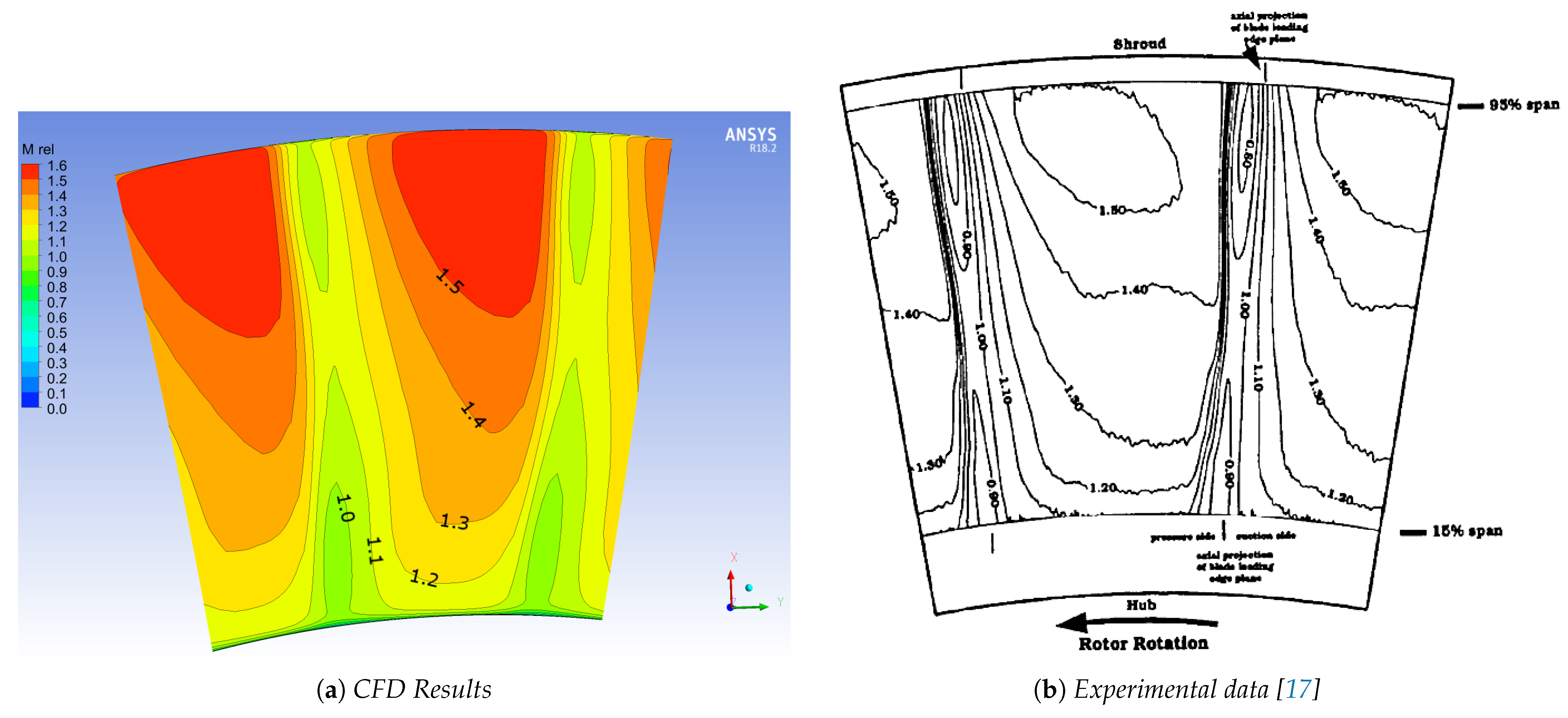
Figure 11 and
Figure 12 show the cross-channel relative Mach number contour plot considering a two blade portion of the circular annulus. The upstream location corresponds to the station 1a (5% of rotor chord), while the downstream location is the station 3 (
Figure 5).
Figure 11 describes the flow field immediately upstream the blade, highlighting the compression wave formed on the pressure surface and the expansion wave grown from the suction side. The contour pattern of the CFD results precisely matches experimental data, showing the same maximum Mach number of 1.5.
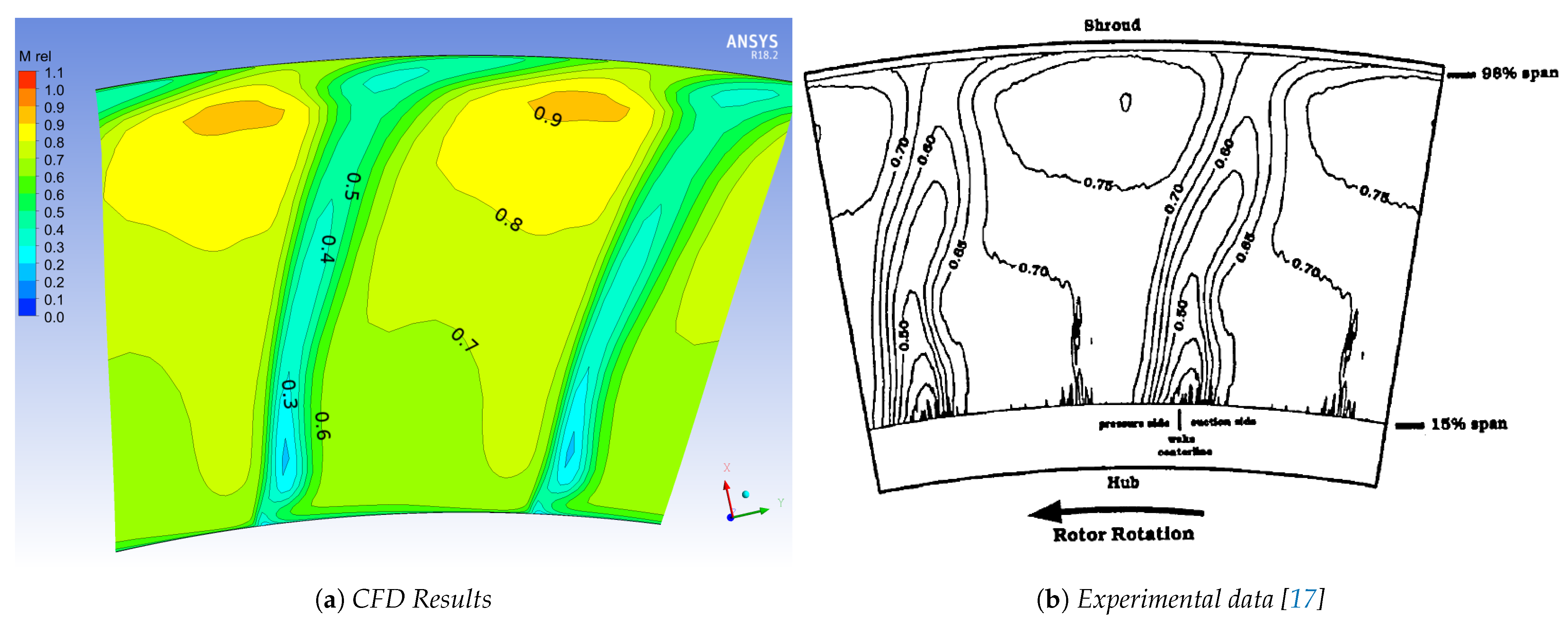
The flow field generated downstream the blade is shown in
Figure 12: it is subsonic and mainly characterized by the rotor wake. The rotor wake can be considered as the central narrow region delimited by the 0.6 contour line, and it extends from the hub to the shroud. In the endwall region, the influence of the tip gap flow modifies and bends the contour lines in this area [
17]. Once more, CFD results are reliable, describing carefully the experimental observations concerning the flow field.
The shock system is highlighted in
Figure 13. A lambda shock, extending from the leading edge to the suction surface of the adjacent blade, is clearly discernible. The shock strength causes the flow to decelerate from Mach 1.4–1.45 to Mach 0.7–0.8. Furthermore, the expansion fan can be observed in the suction side of the blade surface. In this region, the flow suddenly accelerates achieving a Mach number of 1.6. The computational simulations carefully captured the shock wave system with great accuracy, resolving the sharp variation of velocity due to the lambda shock near the suction side and the expansion fan near the blade leading edge.
6. Results and Discussion
In this section, results of all configurations are presented in terms of compressor characteristic curve, stall margin improvement, and adiabatic efficiency variation, and then compared to the smooth wall case. First, the baseline configuration is considered, highlighting the influence of the groove in the flow field near the blade tip. Then, the modification of the tip leakage flow due to the groove is shown and linked to the stall inception delay. Finally, the performances of the T-shape grooves are presented and compared to the baseline and smooth wall cases.
6.1. Tip Flow Modification
The interaction between the tip clearance flow and the main passage flow triggers a rolling-up mechanism that strengthens the tip leakage vortex downstream. At the near-stall point condition, the interaction intensity between the vortex and the shock wave is so severe that the vortex core expands and generates a vortex breakdown zone [
13]. Therefore, a region characterized by a low speed flow is established, blocking the mainstream of the rotor enough to excessively increase the flow angle at the leading edge. This phenomenon leads to the separation of the flow from the blade suction surface, causing the rotor to stall [
15].
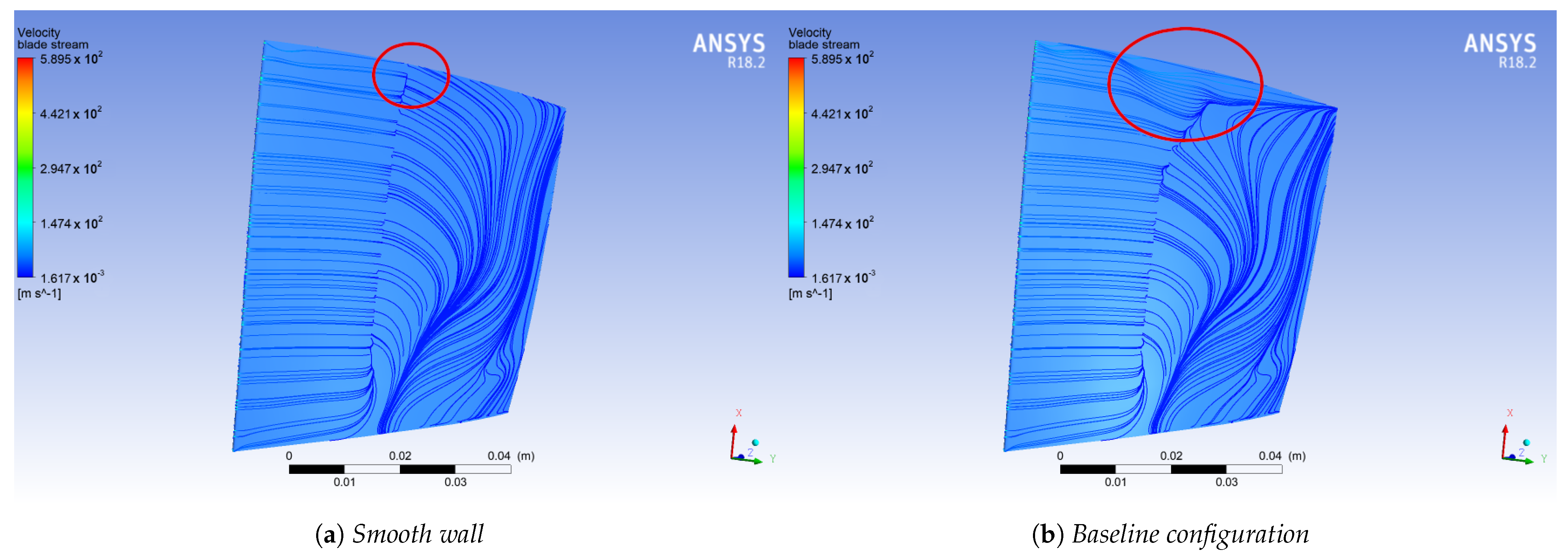
The effects of the groove in the flow field modification are shown in
Figure 14, where the relative Mach number contour at 98% span at the near-stall point of the smooth wall case is represented. The gray area depicts the groove position.
It is evident that the flow field is changed downstream from the groove location: a new stagnation area appears in the mid-passage region. The low flow speed that characterizes this zone is due to the interaction and mixing between the high speed flow exiting the groove domain and the tip leakage vortex. Closer to the blade suction surface, the size of the flow separation is strongly reduced and pushed downstream near the trailing edge: the flow seems to be no longer detached and its speed is increased.
The flow interaction with the passage shock is the main feature of a transonic compressor that triggers the separation on the suction surface, due to the adverse pressure gradient experienced by the boundary layer. If the strength and position of the shock is changed, the stall inception will be delayed. This is what happens when the groove is added.
Figure 15 shows the surface streamlines on the blade suction side at the near-stall point for the smooth wall case.
Focusing on the blade tip region, it is clear that the shock wave is interrupted by the new flow field introduced by the groove and that the separation is suppressed.
It is thought that this particular flow mechanism depends also on the axial position of the groove. The 20% axial location used in this work configurations was not a random choice: it corresponds to a position just upstream from the shock wave interaction with the surface boundary layer in the smooth wall case. This way, the flow exiting the groove is able to modify the shock strength.
6.2. Grooves
Figure 16 shows the rotor characteristic in terms of total pressure ratio versus normalized mass flow rate for all the T-shape configurations compared to the smooth wall and baseline cases. As it can be seen, the addition of a circumferential groove to the compressor case substantially modifies the rotor performance.
The mass flow rate at which the compressor stall occurs is shifted to the left to a lower mass flow rate. However, this benefit is followed by a reduction in the pressure ratio absolute value at the same normalized mass flow rate and a left shift of the choking mass flow rate (20.87 kg/s) for all of the configuration.
Focusing on
Figure 17, the same effects can be seen in the Adiabatic Efficiency graph. In addition, it is evident that an efficiency loss is recorded when the grooves are placed over the blade and that the peak efficiency condition occurs at a lower mass flow rate compared to the smooth wall case. Since the peak efficiency mass flow rate is almost the same for all the groove configurations, the stall margin improvement is mainly influenced by the reduction of the near-stall point mass flow rate.
For each configuration, the stall margin improvement and the efficiency variation were calculated referring to Equations (
2) and (
3).
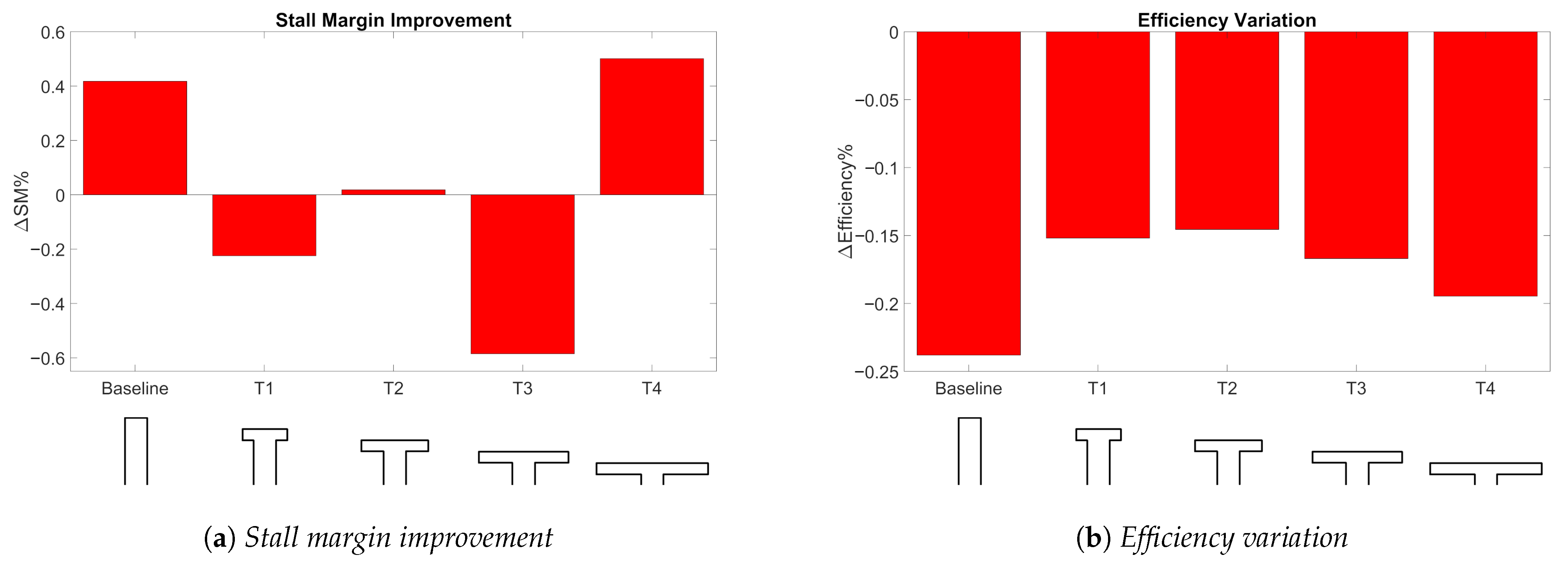
Figure 18a displays the evaluated stall margin improvements for the different T-shape configurations compared to the baseline case.
Although all the configurations have pushed the stall point to lower mass flow rates, only the T2 and T4 configurations are effective, improving the near-stall performance with respect to the smooth wall condition. This happens because the reduction of the stall point mass flow rate is not enough to compensate for the decrease of the peak efficiency mass flow rate triggered by the groove. The stall margin definition takes into account this mechanism, resulting in a curtailment of the compressor operating range for the T1 and T3 configurations. The T4 case shows the maximum value of 0.50% that is slightly higher compared to the baseline performance (0.42%). The baseline stall margin improvement value is quite low compared to the results obtained by Sakuma et al. [
12], who calculated a stall margin improvement of 3.5%. The discrepancy is probably due to different computational settings such as the solver type, the turbulence model, and the method used to glue the main passage and groove meshes.
Figure 18b displays the adiabatic efficiency variation for all configurations. It is evident that the introduction of the grooves produces an efficiency loss: the T2 configuration generates the minimum value, while the baseline the highest. However, the module is always less than 0.25% and, therefore, negligible. Since all the configurations share the same groove width and axial location, the delay of the stall inception is triggered by the same mechanism previously described for the baseline.
Observing
Figure 18a again, some other considerations can be drawn about the stall margin trend. A monotonous reduction of the stall margin was expected moving from the T1 to the T4 configuration and decreasing the groove depth. On the contrary, a non-uniform trend was observed, recording the maximum stall margin value in correspondence with the shallowest groove. An explanation of this tendency could be the fact that all the grooves share the same volume. Moving from a configuration to another, not only the depth, but also the length
a of the horizontal arm change simultaneously. Therefore, the final result is a combination of the effects of the two parameters. It would be wise to investigate in the future the variation of those parameters one by one, to better understand their particular effects on stall margin improvement.
One step further in this direction was made with the configurations T5 and T6. They investigate the effect of a change in the geometrical parameter
a compared to the baseline and T1 configuration, respectively (see
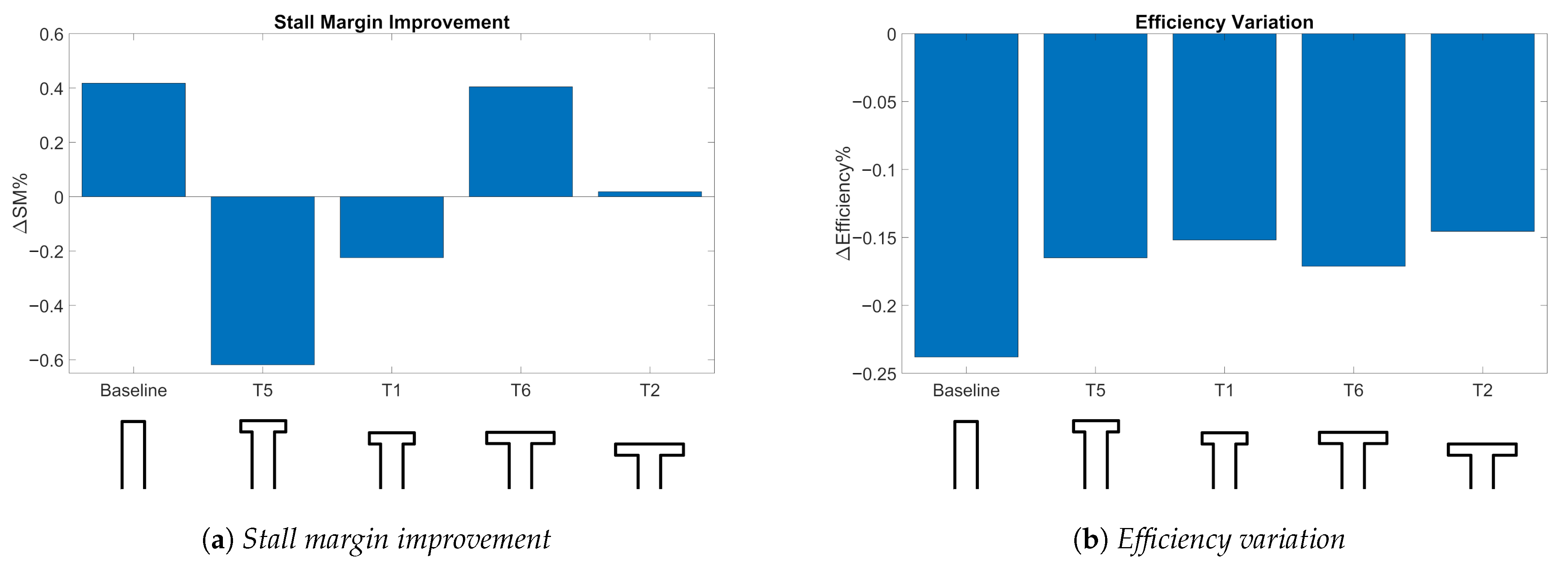
Figure 4). The length of the groove horizontal arm is increased, keeping the same groove depth: the result is a change in the total volume. The performances of the new configurations are displayed in
Figure 19a,b. Configuration T6 shows a high stall margin improvement comparable with the baseline configuration and a lower efficiency variation.
Results are difficult to analyse because they do not reveal a homogeneous trend. Keeping the same groove depth and extending the horizontal arm, a worsening of the stall margin is obtained for the T5 configuration compared to the baseline, while an improvement is recorded for the T6 configuration with respect to T1. Furthermore, maintaining the same value of a and decreasing the groove depth (comparison between T5 and T1), a stall margin improvement occurs in contrast with configurations T6 and T2. Anyway, it seems that a precise value of a defines a particular groove behaviour: T5 and T1 produce a negative stall margin variation, and, on the contrary, T6 and T2 a positive one.
The obtained results have highlighted the fact that the T4 configuration should be chosen to improve the compressor performances. However, the geometry complexity of the T-shape configuration is clearly greater than a rectangular shape, resulting in a more difficult machining and, probably, higher costs of production. Despite these drawbacks, the real advantage is the thickness of the case: using the T4 configuration, the depth of the groove is one third of the baseline. This way, the case will be thinner, resulting in a cheaper and above all lighter compressor, suitable for aerospace applications.
7. Conclusions
The aim of this work was to contribute to a better understanding of how circumferential grooves work and to investigate new potentially effective shapes.
Three-dimensional steady state simulations were carried out using the commercial code ANSYS-CFX. A rectangular groove was initially investigated in order to provide a baseline configuration for further new shapes and to better understand the flow modification generated by the casing treatment. It was demonstrated that the addition of the groove actually shifts the characteristic curve to the left, lowering the mass flow rate at which stall occurs. At the same time, the choking mass flow is reduced and a pressure ratio decrease and efficiency losses are recorded.
The stall margin definition was used to judge the groove performance, taking into account the peak efficiency mass flow rate reduction. The tip leakage vortex, emanating from the leading edge, is weakened and interrupted by the flow exiting the groove. This way, the vortex breakdown is avoided, delaying the stall inception mechanism. Furthermore, 98% span relative Mach number contours highlighted the presence of a new low speed region located in the middle of the passage and generated by the mixing of the two flows. On the other hand, near the blade suction surface, the separation was suppressed by a well attached high momentum flow. Furthermore, it was shown that the effectiveness of the groove can be explained by its effect on neutralizing the shock wave near the blade tip.
Four T-shape configurations were initially considered and designed to have the same volume of the baseline. Stall margin improvement and adiabatic efficiency variation were evaluated for all the configurations, highlighting a not homogeneous trend. Only the T4 configuration displayed a comparable improvement with the baseline, recording a lower efficiency loss. Other two configurations were investigated keeping the groove depth constant and changing the parameter a. It was found that the T6 configuration improves the compressor stall margin, while the T5 configuration is characterized by the worst negative value.
The T4 groove was considered as the best configuration for compressor performance enhancement. Despite its more complex shape, resulting in a more difficult machining and probably higher cost of production, the T4 configuration is the shallowest groove, enabling the use of a thinner compressor case which reduces the total machine weight. For this reason, it is more suitable for light-weight aerospace applications than the other configurations.
The entire work has demonstrated the effectiveness of a passive control method for the enhancement of compressor stability, validating a computational approach to this problem. However, experimental verifications should be performed in order to support computational data and precisely calculate stall margin improvement values for the different configurations. The results’ variability highlights the fact that the physical phenomenon is driven by a large number of parameters, and that they should be carefully studied one by one. In this case, the optimization approach could be a great technique for future studies.


