Abstract
A unified approach to aircraft mission performance assessment is presented in this work. It provides a detailed and flexible formulation to simulate a complete commercial aviation mission. Based on optimal control theory, with consistent injection of rules and procedures typical of aeronautical operations, it relies on generalized mathematical and flight mechanics models, thereby being applicable to aircraft with very distinct configurations. It is employed for an extensive evaluation of the performance of a conventional commercial aircraft, and of an unconventional box-wing aircraft, referred to as the PrandtlPlane. The PrandtlPlane features redundant control surfaces, and it is able to employ Direct Lift Control. To demonstrate the versatility of the performance evaluation approach, the mission-level benefits of using Direct Lift Control as an unconventional control technique are assessed. The PrandtlPlane is seen to be competitive in terms of its fuel consumption per passenger per kilometer. However, this beneficial fuel performance comes at the price of slower flight. The benefits of using Direct Lift are present but marginal, both in terms of fuel consumption and flight time. Nonetheless, enabling Direct Lift Control results in a broader range of viable trajectories, such that the aircraft no longer requires cruise-climb for maximum fuel economy.
1. Introduction
The determination of optimal aircraft trajectories and the quantification of related performance metrics have always been of fundamental interest for all aircraft operators. In particular, commercial aviation stakeholders have in mission performance optimization one of the most natural ways to gain a competitive advantage, by minimizing operative costs and maximizing profits.
In recent years, in order to meet ambitious sustainability goals, increasingly stringent requirements have been imposed on the operational efficiency of present and future aircraft [1,2,3]. Several scientific investigations have employed trajectory analysis and optimization to evaluate the feasibility of achieving such required improvements. A possible approach is to explore innovative mission schedules and air traffic management procedures for current state-of-the-art commercial aircraft [4,5]. However, the well-refined tube-and-wing aircraft configuration seems to have reached its maximum potential, and its efficiency seems stagnant nowadays [6,7,8,9,10]. For this reason, disruptive aircraft configurations have lately received renewed attention as a possible solution towards the sustainable future of commercial aviation [11,12]. With these unconventional aircraft, potential benefits can be achieved in essentially two, non-mutually exclusive ways: a straightforward improvement in aerodynamic or propulsive characteristics and the capability to employ innovative piloting techniques.
The present work focuses on the mission performance analysis and optimization of an innovative box-wing aircraft configuration, referred to as the PrandtlPlane (PrP). The specific version under examination, shown in Figure 1, targets high passenger capacity commercial transport in the short- and medium-range segment, and has been designed within the scope of the Prandtlplane Architecture for the Sustainable Improvement of Future Airplanes (PARSIFAL) project. The box-wing geometry has the highest inherent aerodynamic efficiency amongst lifting surfaces with the same weight and span [13]. The PrP strives to be competitive in future market scenarios by exploiting such property to drastically increase payload capacity w.r.t. its modern competitors, while retaining their overall dimensions. A high aerodynamic efficiency (especially at low speed) and a contained span width are foreseen to have significant impact on relevant performance and operational parameters, such as usability of airport infrastructures (runways and gate slots), smaller number of flights required for an increasing number of passengers, and improved noise impact in proximity of inhabited areas [14].

Figure 1.
PrandtlPlane geometry and top view, with highlighted control surfaces.
The box-wing geometry also allows the presence of redundant control surfaces, and thus offers possibilities for unconventional flight control.
In the case of longitudinal motion, for example, Pure Moment Control can be achieved by appropriately deflecting the front and rear control surfaces in phase opposition. This control strategy makes it possible to generate a net pitch moment with no alteration of total lift. Analogously, Direct Lift Control (DLC) makes it possible to generate a net change in aircraft lift without a change in pitching moment, and can be achieved by simultaneous concordant deflection of the front and rear control surfaces [12,15]. Both of these control strategies can be seen as an extension of Conventional Pitch Control (CPC), for which an elevator deflection generates a tail force far away from the aircraft center of gravity and induces a pitch moment. This comes at the cost of a non-minimum phase behavior and an inherent lag in the longitudinal motion control [16].
When creating a flight mechanics model for unconventional configurations, statistic databases are not representative. For this reason, a completely physics-based, aircraft configuration-agnostic simulation framework has been developed and employed in the present work. This covers all modeling steps required to assess the mission performance of any aircraft configuration, from geometry definition to mission performance evaluation, with selected levels of fidelity. In this way, it is possible to assess the performance of unconventional aircraft configurations, such as the PrP, and compare it to that of other aircraft models in a fair way.
The scientific relevance of the present work lies in the definition, modeling, and simulation of operational mission profiles for any given aircraft model. The focus of the present paper is placed on the abstraction process required to model and link diverse, realistic mission segments within the domain of multi-phase optimal control theory. Particular emphasis is placed on the injection of common piloting techniques, aeronautical practices and regulations, which make the modeled mission realistic from an operational point of view. Finally, with application to an unconventional box-wing aircraft configuration, innovative control methods such as DLC are explored and their impact on the whole mission profile assessed.
The developed framework is employed in a mission performance assessment study with the aim to characterize a selected PrP aircraft model. First, the mission performance of the PrP is compared to that of a prescribed competitor aircraft with conventional geometry, while allowing only classic pitch control. Subsequently, the performance of the PrP is quantified when allowing its redundant control surfaces to achieve DLC, hence enabling the aircraft to modulate its total lift without a change in pitching moment. Results have shown that the PrP configuration under study is competitive in terms of its fuel consumption per passenger. However, this beneficial fuel performance comes at the price of slower flight. The benefits of using DLC are present but marginal, both in terms of fuel consumption and flight time. Nonetheless, enabling DLC results in a broader range of viable trajectories, such that the aircraft no longer requires cruise-climb for maximum fuel economy.
The theoretical background that has served as a starting point for the present research is presented in the following Section 1.1. The paper structure is then outlined in Section 1.2.
1.1. State-of-the-Art Review
The box-wing has been known for a long time to be the “best wing system”, as it minimizes induced drag for a given span and total lift [13]. This property has been confirmed by more recent studies [17,18,19]. While static aerodynamic analyses of box-wing aircraft indicate good induced drag characteristics, no mission performance studies have been conducted yet on an integrated aircraft geometry. For these types of applications, global control optimization techniques deliver the most accurate and comprehensive results.
Originating from the calculus of variations, optimal control theory has become the cornerstone of modern aircraft trajectory optimization [20]. The goal of any optimal control problem is to find the time histories of the states and controls that minimize the cost functional to , while respecting given constraints [21,22,23]. In the most general Bolza formulation, the cost functional is composed of the Mayer end-cost term and the Lagrange running cost , as shown in Equation (1).
Several gradient-based approaches exist for solving such a continuous-time optimal control problem. They are classified on the basis of the set of equations (direct and indirect methods) and the set of variables (shooting and collocation methods) that is discretized [21,24,25,26,27,28,29]. For the present work, a direct collocation approach has been adopted. This provides ease and flexibility in formulating problems and robustness in solving them. Direct collocation methods have been successfully applied to commercial aircraft trajectory optimization, for both conventional mission studies and novel formation flight performance assessments [30,31].
Notably, optimal control applications to mission analysis of unconventional aircraft configurations have not been found in the available scientific literature. A recent mission performance study on an existing commercial aircraft configuration also employs direct collocation methods [26], but makes use of EUROCONTROL’s Base of Aircraft Data (BADA) as its flight mechanics model [32,33]. Such a model is of no use for the performance assessment of unconventional aircraft configurations. Instead, a physics-based flight mechanics model, consisting at least of a set of equations of motion, an aerodynamic model, and a propulsive model, is required.
The equations of motion that are typically used for integral-mission optimization represent the simplified dynamics of a point-mass. Such a reduced-order dynamic model neglects all aspects related to rotational trim, and disregards high-order rotational dynamics due to control effectors [25].
In the optimal control problem formulation, the aircraft lift coefficient is normally used as a control variable together with a classic parabolic drag polar [26,34]. With this approach, the aircraft angle of attack is usually unnecessary for the dynamics integration, and can be disregarded entirely. As a result, its continuity is not taken into account either, such that instantaneous attitude changes and discontinuities can occur. This undesired phenomenon can be remedied by using the aircraft attitude rate as a control variable instead.
To simulate commercial aircraft trajectories in a realistic manner, a wide variety of approaches is available in literature. For example, BADA prescribes a set of speed schedules as a function of altitude in its airline procedure model [32]. Because the aircraft speed schedule is largely fixed, such an approach heavily limits a solver in its freedom to optimize a trajectory within the bounds of regulations applicable to commercial aircraft, such as Certification Specifications or Federal Aviation Regulations. Another approach to realistic operational modeling uses the notion of capture conditions and flight objectives to define flight phases in operational fashion [35]. A more detailed discussion of these concepts is presented in Section 2.1.1.
1.2. Outline
The following Section 2 illustrates the methods that have been employed to formulate and solve the proposed trajectory optimization problems. Afterwards, Section 3 summarizes a validation study with respect to the results of a trajectory optimization problem found in scientific literature. Applications of the proposed approach are then presented in Section 4. In particular, the results of a performance assessment of the PrP with respect to a competitor aircraft are presented in Section 4.1, while the impact of allowing DLC on the performance of the PrP is assessed in Section 4.2. Finally, Section 5 highlights the main findings and contributions presented in this work.
2. Methods
This portion of the present work details the adopted generalized approach to trajectory optimization. Section 2.1 illustrates a robust formulation for a generic trajectory optimization problem, in the framework of optimal control theory. Section 2.2 focuses the attention on the modeling of specific, realistic commercial aviation flight phases and operations. Section 2.3 presents the adopted flight mechanics model. Finally, Section 2.4 highlights the programmatic environment developed to solve the problem numerically.
2.1. Mission Model
A commercial aircraft mission profile is inherently composed of several flight phases with different characteristics. For this reason, multi-phase optimal control methods are naturally applicable to mission performance analysis problems. This section presents a general method to translate an intuitive and realistic aircraft trajectory model into its multi-phase optimal control problem counterpart.
2.1.1. Capture Conditions
To simulate realistic commercial aviation flight procedures, flight phases can be characterized by a certain subset of constant flight parameters, referred to as flight objectives, and flight phase termination conditions, referred to as capture conditions [35]. Flight objectives serve the purpose of modeling classic pilot procedures. Capture conditions ensure the convergence of the whole mission simulation, through proper linkage of flight phases. If a capture variable, i.e., a flight parameter that is “monitored to determine the junction of the current segment with an adjacent one” [35], reaches its threshold value, the capture condition is satisfied and the simulation switches to the new mission phase. Specific capture conditions for several typical flight phases are presented in more detail in Section 2.2.
Although imposing capture conditions and prescribing flight objectives is necessary only for time-stepping, locally optimal trajectory simulations, this is not strictly the case for integral, globally optimal control approaches. Nonetheless, the concepts of capture conditions and flight objectives are an intuitive and realistic representation of real-life operations, and are thus adopted in the current methodology, using them wherever applicable.
2.1.2. Constraints
As explained in Section 1.1, the aircraft flight envelope is limited in several ways by physical considerations. Together with operational limitations, these can be injected in the optimal control framework as various forms of constraints on flight variables.
In the first place, the set of differential-algebraic equations of motion is the most fundamental physical constraint that the system has to comply with. These are referred to as dynamic constraints and synthetically expressed in terms of state and control variables in Equation (2). The actual implementation of such equations is shown in Section 2.3.1:
Additionally, path constraints can be imposed to continuously restrict the trajectory during each mission phase. In general, these constraints can be formulated as in Equation (3), where the inequality constraint can become an equality constraint if equal lower and upper bounds are imposed:
Similarly, bound constraints can be imposed to constrain variables between a fixed minimum and maximum value, at all times. It must be underlined that bounds are mathematically equivalent to path constraints, if the constraint function coincides with the bounded variable. From a numerical solver standpoint, though, they are treated in a substantially different way. Constraints generally increase problem complexity whereas bounds decrease it. The default bound constraints used for the applications presented in this manuscript are reported in Table 1.

Table 1.
Default bound constraints imposed on state and control variables.
In a different manner, phase endpoints constraints can be imposed on time and state variables to constrain them at the interface between two phases. They can be formulated directly, as an explicit prescription of desired values, or indirectly, by defining an event constraint function, as shown in Equation (4):
A specific, indispensable instance of phase endpoints constraints are phase linkage constraints. These ensure that time and states are continuous at phase interfaces, by requiring that the state variables and time should be equal at the end of phase p and at the start of phase :
This result is obtained by modeling as the difference between two phases trajectories at their common interface, and setting both the lower and upper bounds equal to zero. Periodic variables, such as the heading angle, are instead linked by using a sinusoidal function.
The optimal control transcription method adopted for the current work, presented in Section 2.4.2, does not allow setting event constraints as a function of control variables. For this reason, the continuity of the controls at phase interfaces cannot be guaranteed.
Lastly, selected mission boundary conditions are imposed on the aircraft states and controls. These concern the initial condition of the first phase and final condition of the last phase. For commercial aviation missions like all of those presented in the current paper, a mission boundary condition is imposed to ensure that the overall distance flown at the end of the mission equals the specified mission range. Another mission boundary condition ensures that the aircraft arrives at its destination at its Zero Fuel Mass (ZFM). In this way, the aircraft is driven to burn all of the available fuel by the end of the mission. This means that regulatory contingency fuel requirements are disregarded. The initial takeoff mass of the aircraft is determined accordingly by the solver, and limited by the imposed upper bound Maximum Takeoff Mass (MTOM) value.
2.1.3. Cost Functional
The mission cost functional is set to minimize a linear combination of the total flight time and fuel consumption, both good indicators of an aircraft Direct Operating Costs [31]. By defining a Cost Index (CI) as in Equation (8), and prescribing its value for a given mission, the monetary impact of fuel usage can be traded off against that of turnaround time [26]. The overall mission cost can then simply be determined as in Equation (9).
A null CI will drive the trajectory to its minimum-fuel solution. Contrarily, the trajectory will tend to its minimum-time solution as the CI tends to infinity. Finally, a unit CI will result in a trajectory which minimizes both fuel usage and mission time with equal importance. In the remainder of the article, these three trajectories are referred to, respectively, as efficient, fast, and balanced.
2.2. Mission Phase Stereotypes
On the highest level, a nominal commercial aviation mission can be divided into a takeoff, climb, cruise, approach, and landing phase [26]. Additionally, a critical mission profile may also include a holding (or loitering) phase, and a diversion phase to another airport [36]. On a more-detailed level, each of those phases can be in turn broken down into more specific, shorter flight segments.
In order to easily create a consistent, well-posed mission profile model for optimal control problem formulations, typical flight operations and piloting schedules have been formalized in a set of phase stereotypes. These are specific mission segments definitions and implementations, based on only few top-level parameters, which collect and couple all relevant sets of constraints and capture conditions relative to each phase. Their formulation is synthetically presented in Table 2.

Table 2.
Mission phase stereotypes synopsis.
Climb and descent are substantially mirrored phases, the latter terminating at a specified Final Approach Point (FAP). Cruise stereotypes can be used to assemble a variable number of level flight segments connected by step climb segments. Their length and duration are flexibly determined on the basis of the other mission phases, in order to match the prescribed total mission range.
2.3. Flight Mechanics Model
The PrP has been designed within the PARSIFAL project for a range of 4000 km, in the attempt to address the forecast increase in air passenger demand in this range segment [44]. With a passenger capacity about double that of an Airbus A320, and with the same wingspan, the PrP is intended to use existing airport infrastructure due to its compliance with the International Civil Aviation Organization 4C aerodrome specification [45], thereby relieving pressure on congested airports. Because of its vast popularity over similar range segments, the Airbus A320 has been identified as the main competitor of the PrP. An equivalent common research aircraft model, the CeRAS Short Range - Version 01 (CSR-01) [46], has been used in the present work for performance comparison. A selection of some top-level design parameters of both the PrP and CSR-01 is shown in Table 3.

Table 3.
Top-level design requirements of the PrandtlPlane and CSR-01 aircraft.
Any powered aircraft flight mechanics and performance model is composed of at least three main components. The following Section 2.3.1 presents the equations of motion that constitute the physics core of the developed flight simulation framework. The aerodynamic model is then discussed in Section 2.3.2 and the propulsive model is the subject of Section 2.3.3. Lastly, some considerations on the proposed choice of state and control variables are presented in Section 2.3.4.
2.3.1. Equations of Motion
The aircraft is modeled as a point mass flying over a flat and non-rotating Earth model. The International Standard Atmosphere model is adopted, together with the assumption of constant gravitational acceleration and still air. An important implication of the point mass assumption is that aircraft rotational dynamics, such as pitch equilibrium, cannot be modeled. This assumption is necessary to contain the computational complexity of the simulation, and is justified for mission analysis simulations [25]. Adopting a flat Earth approximation is also acceptable as long as the purpose of the investigation is to assess and compare aircraft performances on a generic mission profile, rather than studying real-world point-to-point navigation problems.
Equations of motion are derived in a Cartesian, topocentric reference frame [20,47]. The aircraft attitude and instantaneous trajectory are calculated using a formulation based on the air path reference frame [48]. This is proven to be more accurate and less computationally demanding than an approach based on the Euler angles [47]. The latter can easily be calculated from the body rotational rates using the classic kinematic auxiliary equations [49]. The adopted equations of motion are reported, in vector format, in Equation (10). Further details behind the choice of state and control variables, and their impact on computational efficiency, are given in Section 2.4.
These equations can easily be simplified to describe particular types of flight. For example, coordinated flight is obtained by setting , level flight is enforced by setting , and 2D flight in a vertical plane can be obtained by constraining and . In a similar way, the ground reaction forces are calculated for the on-ground flight phases by solving for vertical and transverse equilibrium, , while they are automatically set to zero in phases in which the aircraft is in flight.
The system of dynamic equations is closed by expressing aerodynamic and reaction forces as functions of the angle of attack, angle of side-slip, the Mach number, and the body angular rates. The engine thrust and fuel consumption are functions of the altitude, Mach number, and the normalized throttle setting. These models are explored more in depth in the following sections.
2.3.2. Aerodynamic Model
A vast baseline aerodynamic dataset has been generated for both the PrP and the CSR-01, in the form of look-up tables, by making use of the Vortex Separation Aerodynamics (VSAERO) panel method code [50]. Aerodynamic forces are expressed as the following superposition of effects:
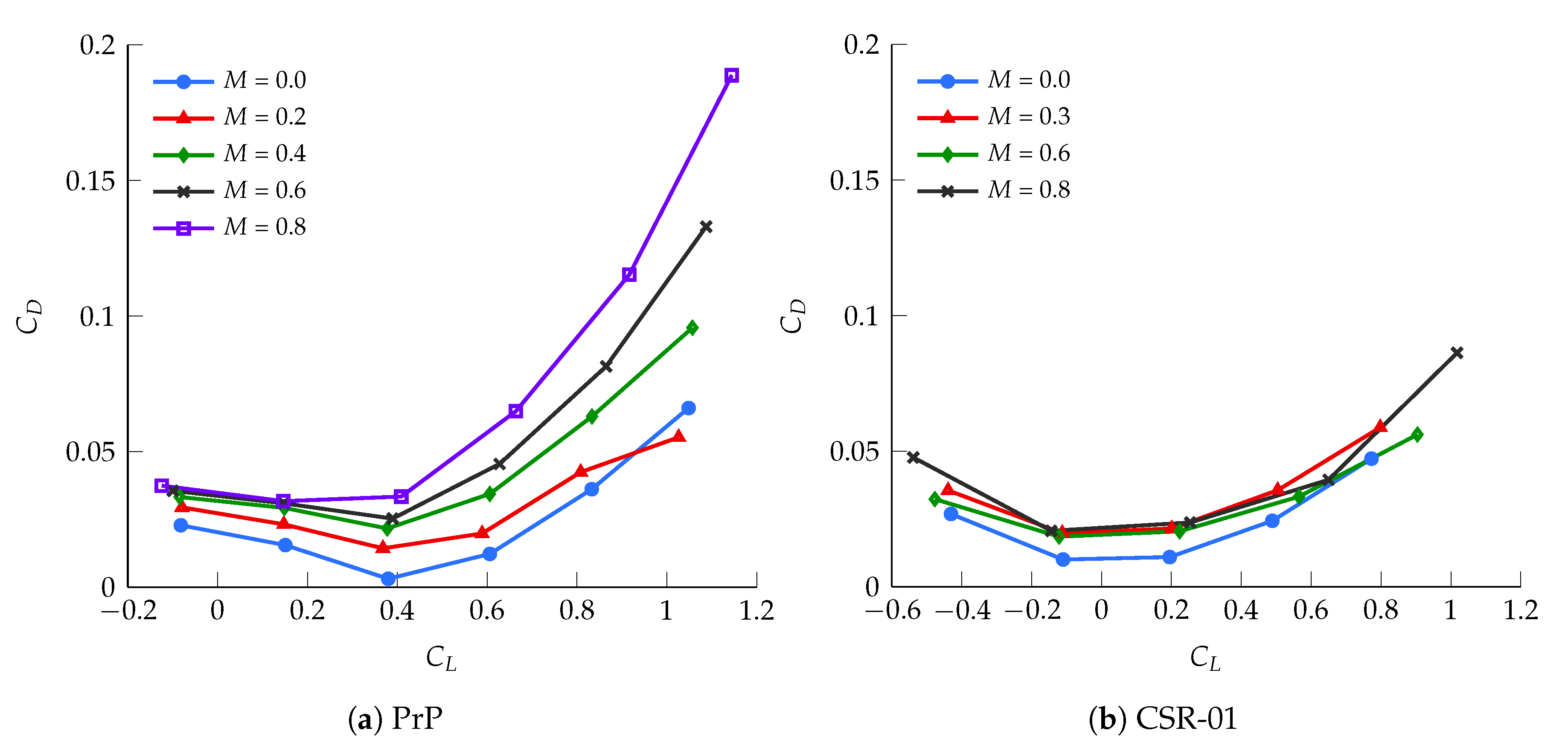
Anticipating the requirements for the optimal control problem solver, presented in Section 2.4.2, the tabular data have subsequently been interpolated using a twice continuously differentiable spline function. The final clean lift and drag polars of the PrP and CSR-01, corresponding to the first term in Equation (11), are shown in Figure 2.
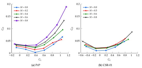
Figure 2.
The lift-drag polar of the (a) PrP and (b) CSR-01 as a function of Mach number.
A constant lift and drag coefficient increase due to high-lift devices deployment is added to the tabular data during the takeoff and landing mission phases. The lift coefficient increase at a given angle of attack is assumed to be , on the basis of a conservative representation of the values reported in [51]. The same value is taken for the PrP and the CSR-01. For the former, preliminary VSAERO lift coefficient data due to flaps indicate that this value is feasible. For the latter, existing references indicate that this value is reasonable and even somewhat conservative [52]. In a similar fashion, the drag increase due to high-lift devices is taken for both as [52].
In order to allow trajectory control in terms of DLC, control surface deflections of the PrP have to be mapped to a corresponding lift and drag coefficient increment, and . To accurately capture drag effects in compressible flow, a fully empirical relation is implemented [53]. It expresses the 2D incremental lift coefficient and the corresponding 2D incremental drag coefficient of a flat plate, due to a trailing edge plain flap deflection, as a function of the product between the Mach number and the flap deflection, . A quadratic fit through the experimental data points and a linear fit through the ones are implemented. The 3D aerodynamic coefficients corresponding to each control surface are then obtained by scaling by the ratio between the flapped wing area and the aircraft reference area, as shown in Equation (12).
Finally, an additional, penalizing vortex drag term is added to account for 3D induced drag effects, as shown in Equation (13) [54]. The span efficiency factor is assigned a value of , which characterizes the box-wing configuration according to [19]. Although representing the airfoil by a flat plate is a crude approximation, it is not the aim of this work to model the control surface transonic aerodynamics in detail. The purpose of this model is to have a realistic and balanced approximation of the attainable control lift and the associated drag penalty.
2.3.3. Propulsive Model
The engine model is created using an in-house, component-based gas turbine analysis tool, referred to as GTpy [55]. The tool evaluates design and off-design engine performance by coupling to the Gas turbine Simulation Program [56], and completely sizes the engine interior and exterior shape by using the TASOPT methodology [57]. The resulting dataset consists of look-up tables that express engine thrust and specific fuel consumption as a function of h, M, and .
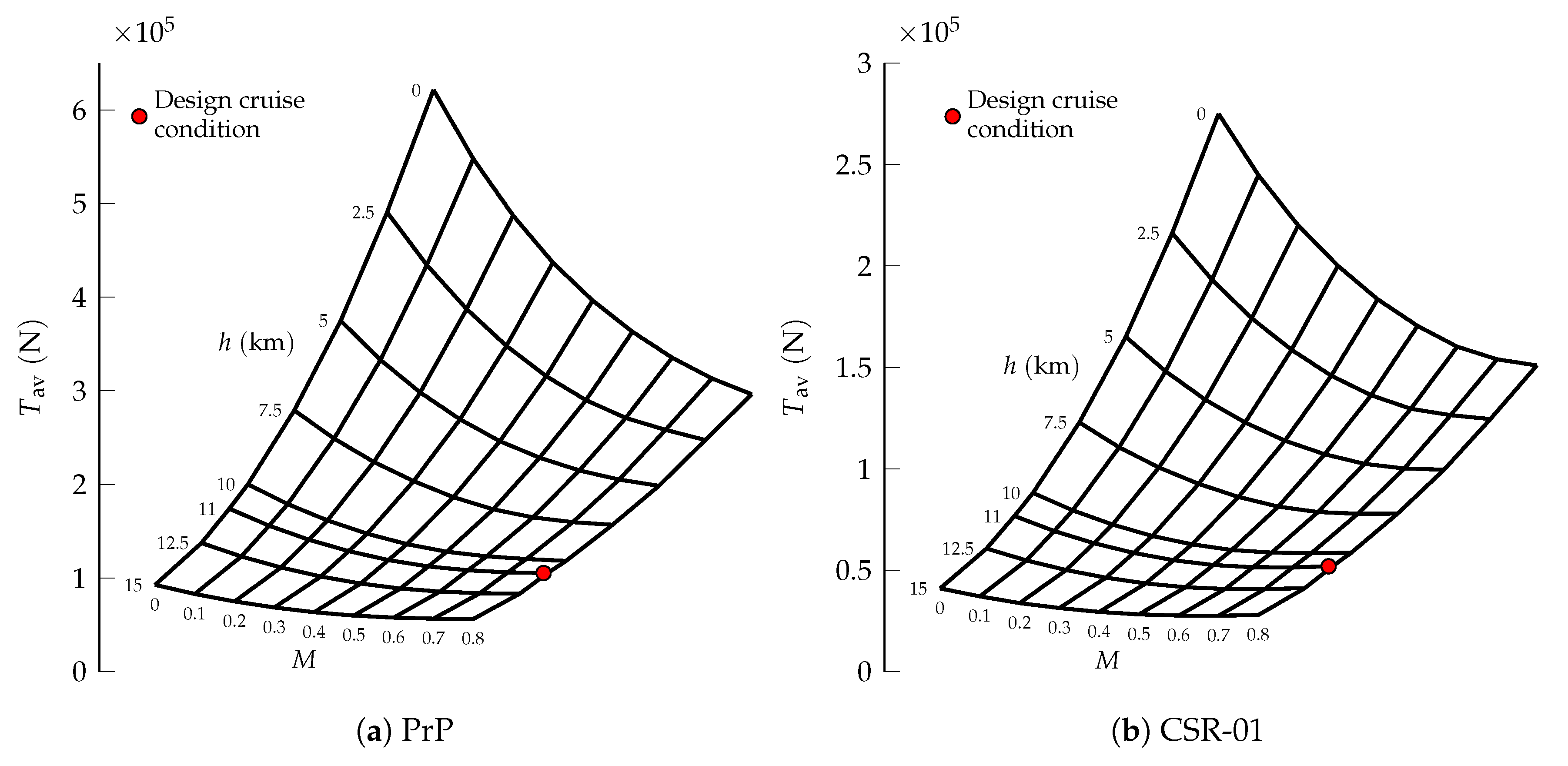
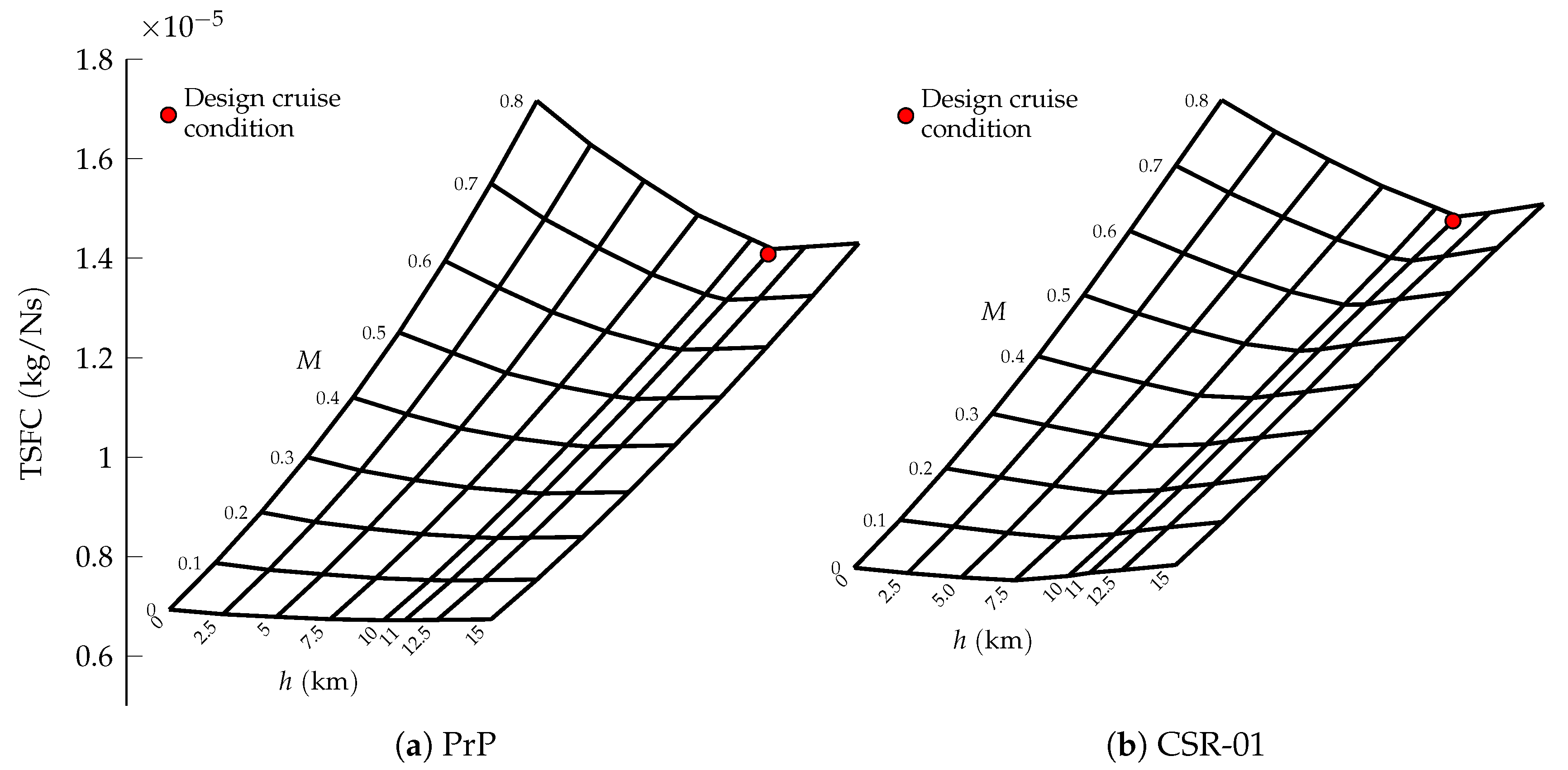
Whilst the PrP has been designed with a tailor-made propulsive system, the CSR-01 has been equipped with a modern CFM LEAP-1 engine model [58]. The total available thrust and Thrust Specific Fuel Consumption (TSFC) maps at maximum throttle are shown for both aircraft in Figure 3 and Figure 4. The maximum thrust available for the PrP is about double the one available for the CSR-01, in light of the similar difference in weight between the two aircraft. Both engine models feature a Bypass Ratio equal to 11, with comparable TSFC.
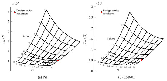
Figure 3.
Maximum available thrust carpet plots for the (a) PrP and (b) CSR-01.
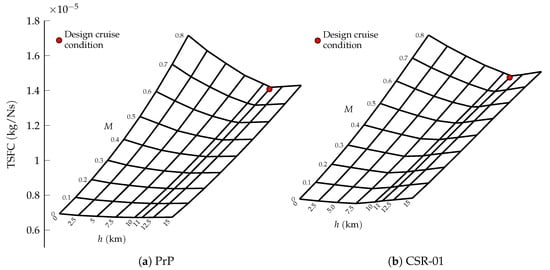
Figure 4.
Thrust specific fuel consumption carpet plots at max thrust for the (a) PrP and (b) CSR-01.
2.3.4. Control Variables
The selected set of states and control variables is reported in Table 4.

Table 4.
Selected grouping of flight parameters into states and controls.
While the states remain unchanged for both application studies on CPC and DLC, the controls are expanded, for the latter, by including the PrP control surface deflections. In particular, the ones corresponding to all of the control surfaces highlighted in Figure 1, except for the rudders. The control surfaces are free to move independently, without any explicit gearing or ganging, with the only constraint being symmetry about the aircraft symmetry plane. This results in four additional, independent control variables.
With this control vector, and together with the aerodynamic model presented in Equation (12), the control surfaces grant the aircraft additional degrees of freedom to modulate its lift, at the expense of extra drag. Because the aircraft is intended as a point mass, no geometry information such as moment arms or positions w.r.t. the aircraft center of gravity are used in the present model. Therefore, the control surface deflections have no impact on rotational dynamics or trim. They have to be intended as an optional, additional deflection to be superimposed to the deflection needed to achieve the required body rotational rates p, q, r.
These rates, in their turn, are actually used to control the aircraft attitude at all times. Preferring these over the attitude angles allows to prevent the insurgence of instantaneous discontinuities in the aircraft attitude time histories. This is easily done by setting appropriate bounds on p, q, r themselves. Additionally, this choice is advantageous as the body rates have an explicit impact on the aerodynamic model described in Section 2.3.2, and hence eliminate the need for computationally costly matrix transformations (e.g., to obtain them from the Euler angular rates). On the other hand, bang–bang control can occur in light of the linear dependence of aerodynamic forces on the body rotational rates, presented in Equation (11). In order to discourage this very unusual control strategy for commercial aviation, the excessive control penalization term shown in Equation (14) is added to the objective functional of Equation (1):
The constant is a measure of the severity of the control penalization. Generally, setting a very small value for suffices, for it makes the objective function non-linear in the controls. As a result, the impact of on is negligible [59].
2.4. Simulation Environment
The in-house developed simulation tools and the already available optimization solvers employed for the current analysis are briefly presented in the following Section 2.4.1 and Section 2.4.2, respectively, with insight on the whole mission simulation execution flow.
2.4.1. In-House Development
For both aircraft under study, the aircraft geometry model is created in the Multi Model Generator (MMG), an in-house developed Knowledge Based Engineering toolbox [60,61]. The geometry is imported from structured input sources [62,63] or other existing models, and processed by exploiting the Open Cascade library [64]. The MMG encodes automatic, aircraft configuration-agnostic modeling and meshing capabilities, which can be interfaced with selected solvers for the extensive aerodynamic characterization of the aircraft required for flight mechanics studies.
Together with the propulsive, mass and inertial models, the resulting aerodynamic database is imported in the Performance, Handling Qualities and Loads Analysis Toolbox (PHALANX). This is a nonlinear flight mechanics simulation and analysis toolbox, which integrates data and sub-models from various aeronautical disciplines to generate a complete flight mechanics model of the aircraft.
PHALANX is developed in MATLAB®/Simulink and it is aircraft configuration-agnostic and data-driven, meaning that its fidelity depends on the data and formulations used in the sub-models. This allows PHALANX to operate consistently at different stages of the aircraft design process. The physics model, in particular, allows for explicitly writing the desired equations of motion, as in the present work, or can revolve around a Simscape Multibody Dynamics core. The latter allows modeling and simulation of systems dynamics without the need to explicitly write the analytical equations of motion.
The toolbox has been used in the past for the positioning and sizing of control surfaces of the PrP [65,66], and the analysis and simulation of novel aircraft configurations like the Blended Wing Body [67] and the Delft University Unconventional Configuration (DUUC), featuring the propulsive empennage concept [68]. In the present work, PHALANX also serves the purpose of a frame environment which contains the execution flow of the optimal control transcription solver and the Nonlinear Programming (NLP) optimizer, as explained in the next section.
2.4.2. Solvers and Execution Flow
To solve the trajectory optimization problem outlined so far, the commercial optimal control transcription software General Purpose Optimal Control Software (GPOPS-II) has been used. This software employs a Legendre-Gauss-Radau direct pseudospectral (orthogonal) collocation method and serves as an optimal control transcription program with built-in mesh refinement and error quantification [69]. At the lowest level, the open-source Interior Point Optimizer (IPOPT) is used as NLP optimization program [70].
If the entire mission is restricted to 2D motion, the redundant equations of motion are automatically removed, globally resulting in fewer degrees of freedom and hence a computationally lighter problem. If 3D flight should not be neglected entirely, 2D constraints can be locally imposed on selected mission phases, as mentioned in Section 2.1.2.
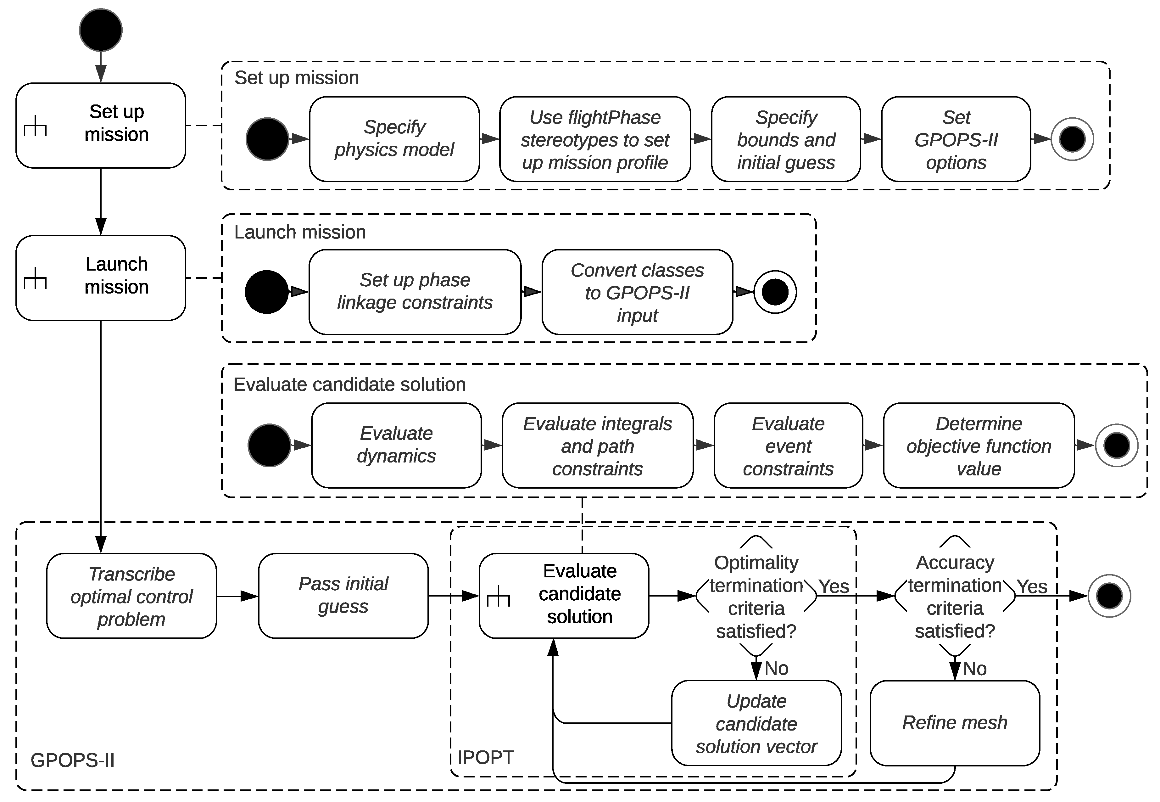
A schematic overview of the execution flow of the simulation framework is shown in Figure 5. This Unified Modeling Language (UML) activity diagram also shows which parts of the program are owned by which software application, keeping in mind that the whole flow is contained in PHALANX.
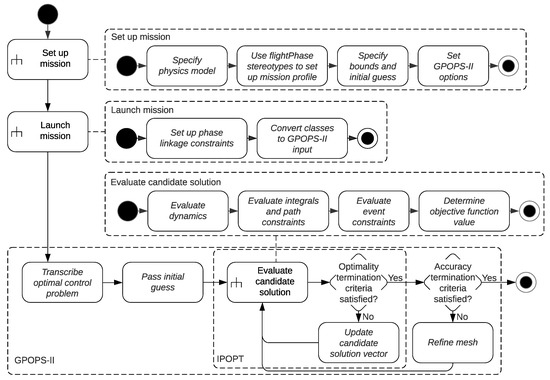
Figure 5.
A UML activity diagram of the trajectory optimization program in PHALANX.
3. Validation
Validation of the framework is performed by replicating the multi-phase trajectory optimization problem found in [51]. This reference study simulates an Airbus A320 flying for minimum fuel from Madrid-Barajas to Berlin-Schönefeld airport, in still air, using BADA 3.6 as an aircraft performance model.
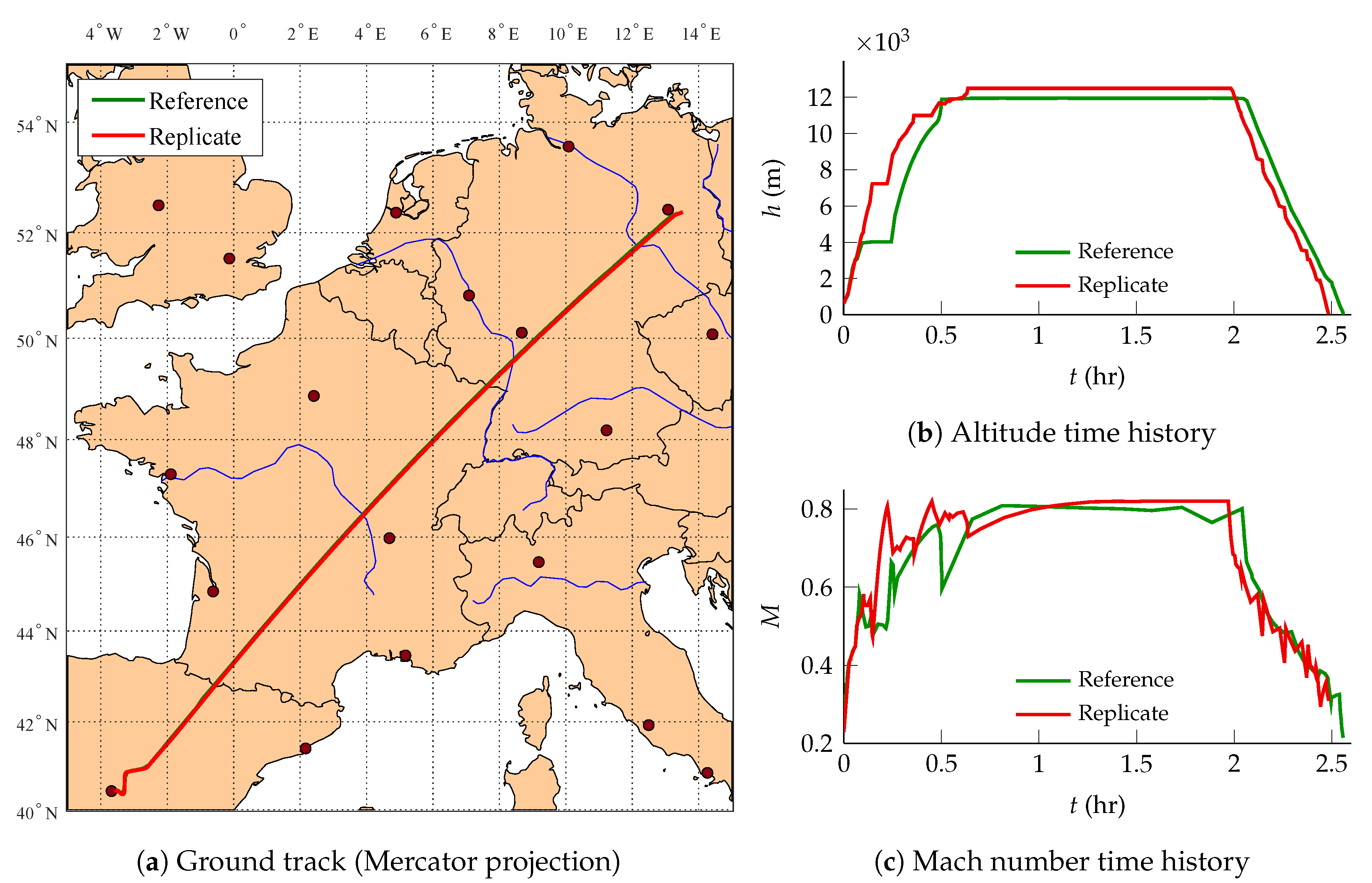
The ground tracks of the reference and replicate trajectories are shown in the Mercator-projected map of Figure 6a, together with the altitude and Mach number time histories of Figure 6b,c, respectively. They are all satisfactorily comparable, but do not overlap exactly. Figure 6b shows that the altitude profile of the replicate trajectory deviates noticeably from the reference one. The former achieves better fuel savings partly by climbing to higher altitudes earlier, whereas the latter is somewhat hesitant in climbing. Figure 6c shows that, in both cases, the aircraft nears its limit, imposed by the underlying BADA operational model.
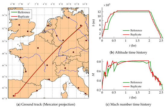
Figure 6.
Comparison between the reference and replicate missions (a) ground tracks, (b) altitude time histories, and (c) Mach number time histories.
A numerical comparison of the top-level performance metrics is presented in Table 5. It is seen that these metrics agree reasonably well and the replicate study is even able to perform slightly better than the reference one. In light of this, the framework is assumed to be validated.

Table 5.
Comparison of optimal top-level performance metrics of the validation mission setups.
4. Results
In the following sub-sections, the performance of the PrP and of the CSR-01 is compared and discussed on the basis of multiple case studies. All case studies are characterized by 2D flight, for which the equations of motion are obtained by setting y, , , p, r equal to zero, and , in order to make the aircraft fly in the x-direction. In every case study, both aircraft fly the same mission profile, defined by Table 2. In particular, the following values are assigned: . During ground roll phases, the rolling friction coefficient is assumed to be constant and equal to 0.02 [71].
4.1. Conventional Pitch Control Performance
Section 4.1.1 deals with presenting the design mission optimal trajectories of both aircraft for several CIs. Then, a maximum-range mission is simulated in Section 4.1.2, to analyze the aircraft off-design performances. Finally, a top-level performance metrics overview is given in Section 4.1.3.
4.1.1. Design Range
The design range requirement is fulfilled by imposing that the distance travelled at the final time instant is . Figure 7 displays the efficient, balanced, and fast trajectories for the PrP and CSR-01, respectively.

Figure 7.
Design mission profile for the (a) PrP and (b) CSR-01, for different CIs.
For its fuel efficient trajectory (), the CSR-01 maintains its initial cruise altitude nicely, whereas the PrP seems to postpone its cruise at the imposed altitude of 11 km. This indicates that the fuel-optimal cruise altitude of the PrP is actually lower than 11 km. Further studies (not reported here for brevity) leaving the initial cruise altitude free to be determined by the optimizer, have confirmed this hypothesis and found an optimal cruise altitude of km.
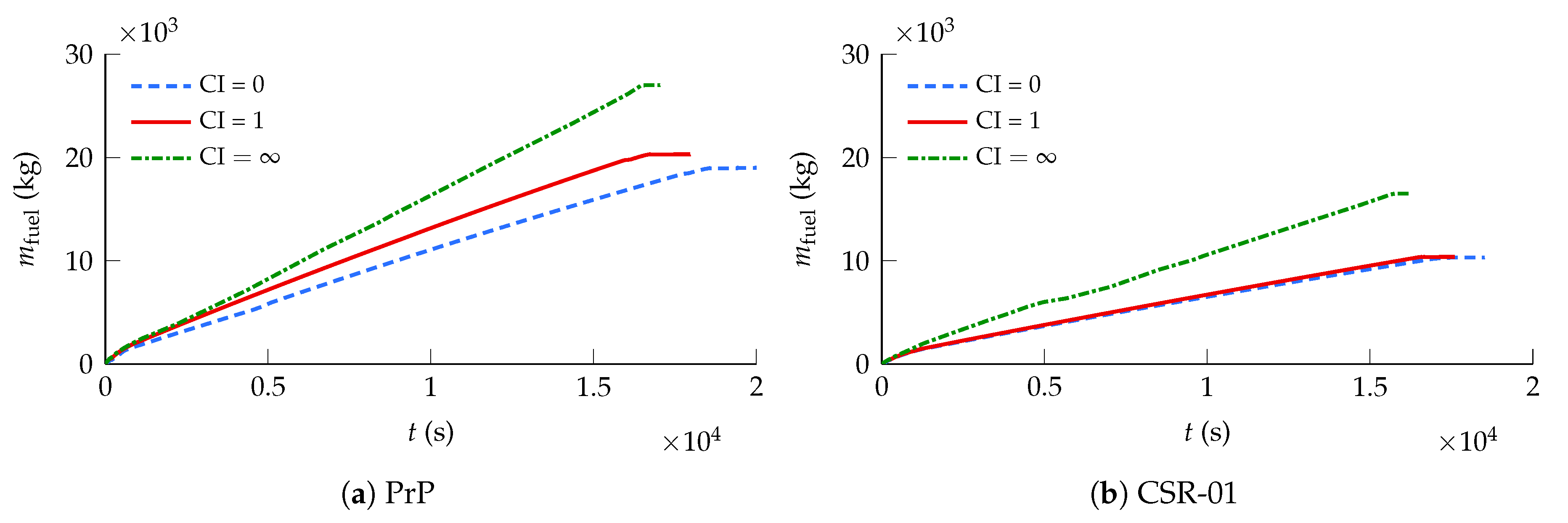
For the balanced trajectory (), the PrP makes use of one step climb, whereas the CSR-01 maintains its initial altitude throughout cruise. The reason for this different behavior can be sought in the fuel consumption. While the mission duration is comparable for both aircraft, the PrP burns approximately double the amount of fuel of the CSR-01, as illustrated in Figure 8. Therefore, a unit CI puts different optimization emphasis for each aircraft. The PrP is driven to a slightly more fuel-efficient trajectory, whereas the CSR-01 tends towards a faster mission. Hence, the PrP climbs during cruise for fuel economy, whilst the CSR-01 seeks greater temporal gain.
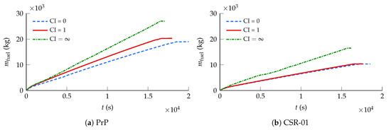
Figure 8.
Design mission fuel consumption for the (a) PrP and (b) CSR-01, for different CIs.
The fast trajectory () drives both aircraft to a low altitude in order to maximize their true airspeed. This happens despite the imposed initial cruise altitude of h = 11 , and is particularly noticeable for the CSR-01. In light of the higher speed of sound at lower altitude and the imposed M < M constraint, flying at a lower altitude increases the maximum attainable flight speed, thereby minimizing mission time. The optimal cruise altitude at which the aircraft establish their trajectory is determined by their respective fuel capacities; both aircraft namely expend all their fuel on the 4000 km minimum-time mission. This means that the aircraft take off at their respective MTOMs because of the imposed terminal state boundary condition = ZFM.
As shown in Figure 9, both aircraft obviously seek the upper limit when flying their fast trajectories. Interestingly, but somewhat unexpectedly, the efficient trajectory of the PrP is flown at a significantly lower Mach number than the one chosen by the CSR-01.

Figure 9.
Design mission Mach number for the (a) PrP and (b) CSR-01, for different ci.
4.1.2. Harmonic Range
For the harmonic mission profile, i.e., the mission that maximizes the range at maximum payload, no boundary condition is imposed on the final position . Instead, the objective function is defined as to maximize the range. In this analysis, therefore, no distinction is made between efficient, balanced, or fast strategies.
The 2D trajectories of the PrP and CSR-01 are shown in Figure 10a, in which the range advantage of the CSR-01 is clearly recognizable. Unsurprisingly, the trends in the altitude profiles show striking resemblance to those in the design mission minimum-fuel trajectories. After all, both maximum-range and minimum-fuel missions seek to maximize the Specific Air Range. The same resemblance holds for the Mach number time histories, shown in Figure 10b; whereas the CSR-01 flies at or near its design cruise Mach number for fuel-economic travel, the PrP flies notably slower. Both aircraft make full use of their fuel capacity at maximum payload. A summary of the performance metrics of the PrP and CSR-01 corresponding to the harmonic range mission is shown in Table 6.

Figure 10.
Harmonic mission performance comparison between the PrP and CSR-01.

Table 6.
The harmonic range performance of the prp w.r.t. the csr-01.
4.1.3. Top-Level Mission Performance Summary
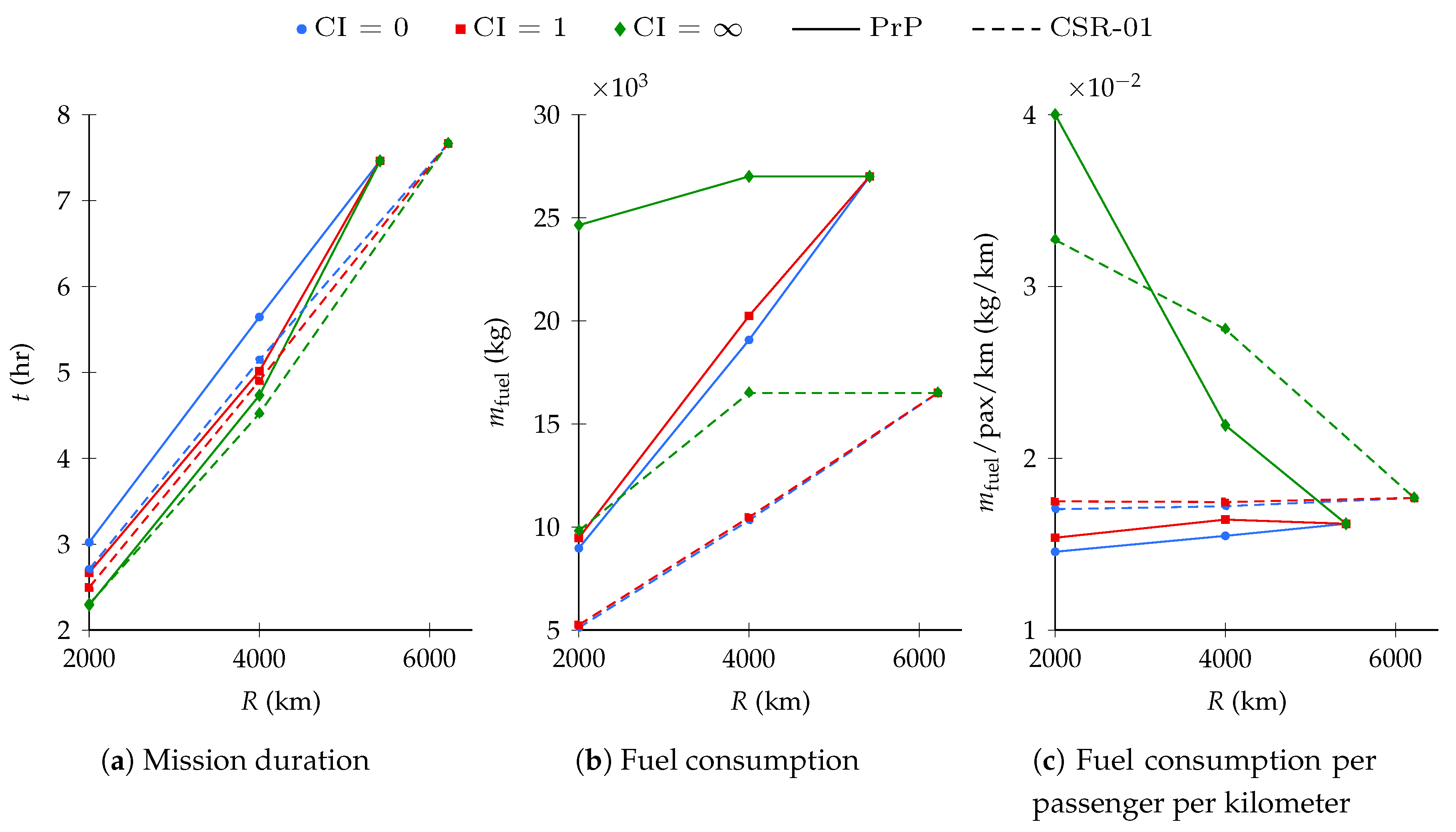
The top-level performance metrics of an additional 2000 mission simulation, the details of which are not reported to promote brevity, are aggregated to those presented in the previous sections and summarized here. The time and fuel performance of both aircraft is shown in Figure 11a,b for several ranges and CIs, as well as the fuel burn per passenger-kilometer reported in Figure 11c.
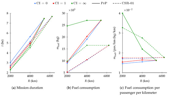
Figure 11.
Top-level mission performance of the PrP and CSR-01 as a function of CI and range.
By flying for minimum time, the PrP is able to decrease its mission duration by nearly 16.2% at the cost of over 41.5% more fuel, with respect to the 4000 km minimum fuel mission. Likewise, the CSR-01 consumes nearly 60% more fuel to fly a 12.1% faster mission. It is thus clear that the fast missions have little application for real life commercial airliners. Indeed, marginal temporal gain induces an enormous fuel expense for both aircraft.
Earlier findings according to which the PrP tends to fly slower than its competitor are confirmed. The CSR-01 has about 10% higher speed on the minimum fuel missions. With the minimum time strategy, its average speed is comparable to that of the PrP on the 2000 km range mission, over 4.5% higher on the 4000 km mission, and nearly 12% higher on the maximum range mission.
Whereas the fuel consumption of the PrP is obviously higher in absolute terms, the PrP carries over twice as many passengers as the CSR-01. The PrP outperforms the CSR-01 in terms of fuel consumption per number of passengers. At a fuel consumption of approximately 15 /pax/, the PrP is 14.5% more efficient than its competitor on the short-range minimum fuel mission, 10v on the design range minimum fuel mission, and nearly 8.5% on the maximum range mission.
In summary, the CSR-01 is more versatile than the PrP due to its higher maximum range. On the other hand, the PrP does confirm the expected performance for which it was conceived and designed: more efficient flights in the short and medium range segment.
4.2. Direct Lift Control
The performance benefits obtained when allowing DLC as a means of attitude control are presented in this section. Such solutions are expected to be at least as good as the ones obtained with CPC. After all, the conventionally controlled optimal trajectory, without deflecting any control surfaces, is still a valid solution to the trajectory optimization problem with DLC enabled.
The altitude profiles and the Mach number of the DLC-controlled missions do not differ substantially from the regularly controlled ones, and are not reported for brevity. In addition, during most mission phases, control surface deflections are highly oscillatory, such that meaningful interpretation of the results is hindered. Therefore, the interpretation of the results will be limited to the cruise phase, as shown in Figure 12. In this phase, it is interesting to note how the aircraft does not deflect the control surfaces excessively. For all three mission strategies, they subtly and continuously decrease in order to adjust for the aircraft weight variation.

Figure 12.
(a) control surface deflections and (b) angle of attack of the PrP using DLC—details of the cruise phase for different CIs.
Only a single movable deflection per mission is visible in Figure 12a because the aircraft deflects all of its movables simultaneously and by the same amount, at all times. This is intuitively explainable in light of the fact that no movable-specific aerodynamics have been implemented in the aerodynamic model, except for a factor scaling the attainable CL and CD per movable. Because no aerodynamic moments are modeled as a function of control surface deflections, the primary effect of the latter is the incremental lift-to-drag ratio, which is equal for all control surfaces for a given deflection.
In its efficient trajectory, the aircraft uses control surface deflections to increase its aerodynamic efficiency. As the aircraft burns fuel and loses weight over time, it decreases the movables deflections to decrease the required incremental lift. At the same time, the Mach number decreases and the angle of attack remains reasonably constant, as shown in Figure 12b.
In the fast trajectory, the aircraft uses the additional controls to generate and progressively increase downforce. At the cost of a slight control drag penalty, decreasing total lift by means of control surfaces limits the angle of attack variation required to maintain constant altitude at constant Mach number.
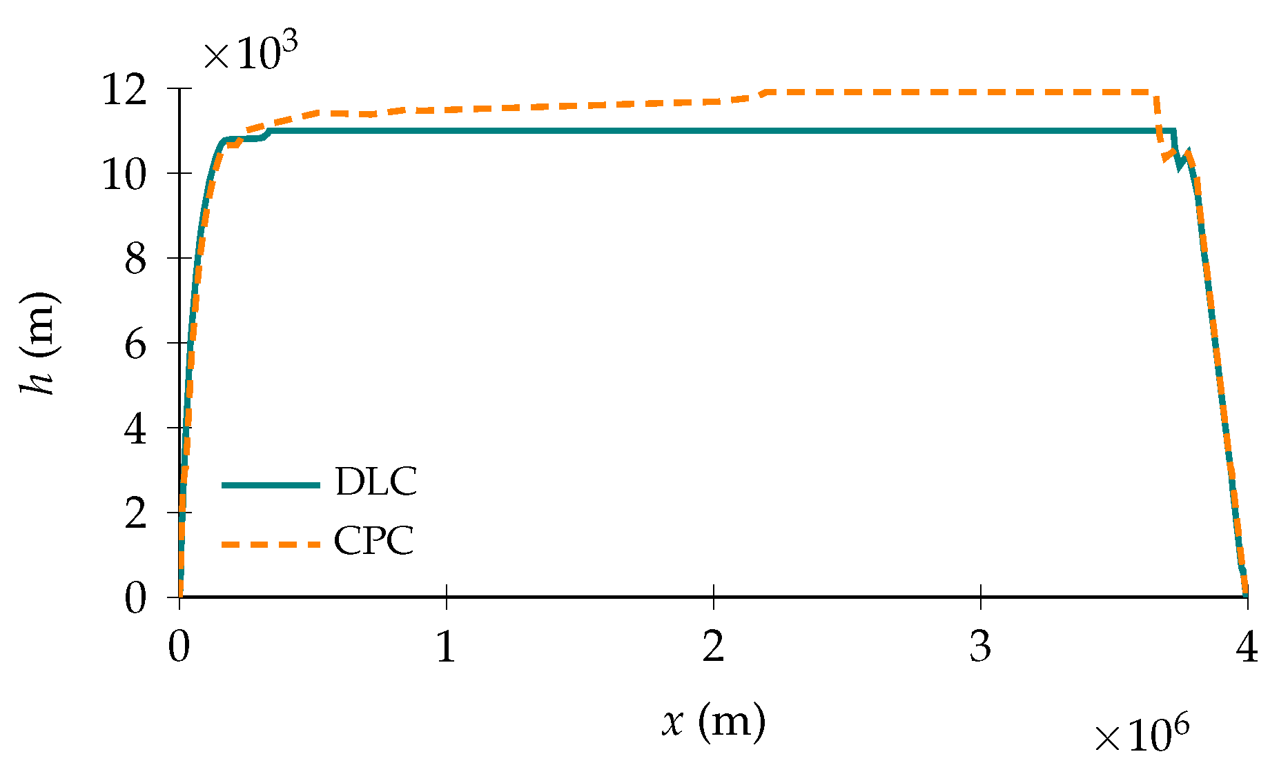
An interesting phenomenon is observed in the altitude profile of a cruise phase simulation in which no constraint is imposed on the minimum or maximum Rate of Climb (RoC). In case of CPC, the aircraft optimal trajectory results in a gradual cruise-climb, which is not compliant with the most common air traffic procedures. With DLC enabled, instead, the aircraft no longer tries to gradually climb during cruise, as illustrated in Figure 13. Including the control surface deflections in the problem formulation gives the aircraft an alternative way to optimize the cruise phase. DLC, in particular, proves as a valid control strategy to deal with the progressive aircraft weight decrease, such that cruise-climb is no longer a necessity for fuel economy.
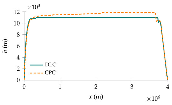
Figure 13.
Comparison of PrP mission profiles with different control strategies and unconstrained RoC during the cruise phase, for a unit CI.
In terms of top-level performance metrics, the aircraft gains only marginally by enabling DLC. On the efficient mission, the fuel consumption is decreased by nearly 0.6%; on the balanced mission, by about 2.5%. The flight time is negligibly decreased by seconds with respect to the regularly controlled fast mission. Table 7 shows a numerical summary of the design mission performance of the PrP when using DLC with respect to its performance when using CPC. In light of the aerodynamic and control surface model used, though, these results should be interpreted with appropriate caution. Additionally, the discretization error due to the numerical resolution of the trajectory optimization problem has not been assessed and has therefore also not been mitigated.

Table 7.
The design mission performance of the prp using dlc w.r.t. its performance using cpc.
5. Conclusions
A unified approach to commercial aviation mission performance assessment has been presented in this work. Special emphasis has been placed on realistic aircraft mission modeling in the framework of multi-phase optimal control theory. Accounting for all the steps, from assembling a complete flight mechanics model to calculating the optimal trajectory, the implemented approach is completely configuration-agnostic, and therefore applicable to aircraft with very distinct geometries.
A first case study has been presented, which compares the mission performance of a box-wing aircraft, referred to as the PrandtlPlane (PrP), to a conventional aircraft with a similar design range, the CeRAS Short Range - Version 01 (CSR-01). With only slight adaptations to the problem setup, missions have been analyzed for various ranges and flight strategies. The analysis has shown that the PrP outperforms its competitor in terms of fuel consumption per number of passengers, although this comes at the price of a significantly shorter harmonic range.
A second case study has been designed to quantify the impact of unconventional control methods on mission performance. Using a simple approximation to model the incremental lift and drag of the PrP as a result of deflecting its control surfaces, the PrP was enabled to use its Direct Lift Control (DLC) capabilities. Using control surfaces to subtly vary the aircraft equivalent camber during cruising, the performance benefits are basically marginal. The projected mission time savings are in the order of seconds, and hence negligible. The fuel savings per passenger per kilometer with respect to its fuel-optimal design mission are estimated to be 0.6%.
Future research may be aimed at testing the assumptions according to which rotational equilibrium is automatically verified and pitch maneuvers are actually achievable with the available control power. Additionally, a more sophisticated model for the incremental lift and drag due to control surface deflections might lead to new insights in the potential benefits of using DLC. Finally, a quantification of the numerical discretization error could be relevant to acquire more confidence in the assessed impact of DLC on top-level mission performance metrics.
Author Contributions
Conceptualization, S.d.W., C.V., and F.O.; methodology, S.d.W. and C.V.; software, S.d.W. and C.V.; validation, S.d.W.; formal analysis, S.d.W.; investigation, S.d.W.; resources, S.d.W., C.V., and F.O.; data curation, S.d.W. and C.V.; writing—original draft preparation, S.d.W. and C.V.; writing—review and editing, S.d.W., C.V.; visualization, S.d.W. and C.V.; supervision, C.V., and F.O.; project administration, S.d.W. All authors have read and agreed to the published version of the manuscript.
Funding
The research presented in this paper has been carried out in the framework of the PARSIFAL (Prandtlplane ARchitecture for the Sustainable Improvement of Future AirpLanes) research project, which has been funded by the European Union within the Horizon 2020 Research and Innovation Program (Grant Agreement No. 723149).
Conflicts of Interest
The authors declare no conflict of interest. whitelineroman whitelinegreek whitelinesub
Abbreviations
The following abbreviations are used in this manuscript:
| Acronyms | |
| BADA | Base of Aircraft Data |
| CAS | Calibrated Airspeed |
| CI | Cost Index |
| CPC | Conventional Pitch Control |
| CSR-01 | CeRAS Short Range - Version 01 |
| DLC | Direct Lift Control |
| FAP | Final Approach Point |
| MMG | Multi Model Generator |
| MO | Maximum Operative |
| MTOM | Maximum Takeoff Mass |
| NLP | Nonlinear Programming |
| OEM | Operational Empty Mass |
| PARSIFAL | Prandtlplane Architecture for the Sustainable Improvement of Future Airplanes |
| PHALANX | Performance, Handling Qualities and Loads Analysis Toolbox |
| PrP | PrandtlPlane |
| RoC | Rate of Climb |
| TSFC | Thrust Specific Fuel Consumption |
| UML | Unified Modeling Language |
| VSAERO | Vortex Separation Aerodynamics |
| ZFM | Zero Fuel Mass |
| Symbols | |
| Roman letters | |
| A | aspect ratio |
| b | wing span |
| constraint function | |
| C | generic constant or coefficient |
| drag coefficient | |
| zero-lift drag coefficient | |
| pressure drag coefficient factor | |
| lift coefficient | |
| D | drag |
| e | span efficiency factor |
| f | state dynamic equations |
| F | force |
| g | gravitational acceleration |
| h | altitude |
| cost functional | |
| Lagrange running cost term | |
| L | lift |
| lower bound | |
| m | mass |
| M | Mach number |
| n | number of mission phases |
| N | reaction normal force |
| p | roll rate |
| q | pitch rate |
| r | yaw rate |
| R | mission range |
| S | wing area |
| t | time |
| T | thrust |
| upper bound | |
| V | velocity |
| x | eastward coordinate |
| y | northward coordinate |
| Greek letters | |
| angle of attack | |
| angle of sideslip | |
| flightpath angle | |
| generic difference | |
| deflection angle | |
| aerodynamic angle of roll | |
| control variable vector | |
| state variable vector | |
| normalized throttle setting | |
| Mayer endpoint cost term | |
| heading angle | |
| angular velocity vector | |
| Subscripts | |
| ae | aerodynamic |
| av | available |
| cr | cruise |
| f | final |
| gd | ground |
| i | initial |
| rot | rotation |
| rw | runway |
| Subscripts | |
| * | optimal |
| p | phase |
References
- Darecki, M.; Edelstenne, C.; Enders, T.; Fernandez, E.; Hartman, P.; Herteman, J.P.; Kerkloh, M.; King, I.; Ky, P.; Mathieu, M.; et al. Flightpath 2050 europes vision for aviation. Off. Eur. 2011. [Google Scholar] [CrossRef]
- Gittens, A.; Poole, J.; de Juniac, A.; Liu, F.; Pie, J. Aviation Benefits. Report, ICAO, AI, CANSO, IATA, ICCAIA. 2017. Available online: https://www.icao.int/sustainability/Documents/AVIATION-BENEFITS-2017-web.pdf (accessed on 15 June 2020).
- Airbus SAS. Global Market Forecast Cities, Airports & Aircraft 2019–2038; Airbus: Blagnac, France, 2019. [Google Scholar]
- Alam, S.; Nguyen, M.; Abbass, H.; Lokan, C.; Ellejmi, M.; Kirby, S. Multi-aircraft dynamic continuous descent approach methodology for low-noise and emission guidance. J. Aircr. 2011, 48, 1225–1237. [Google Scholar] [CrossRef]
- ICAO. Continuous Descent Operations (CDO) Manual, 1st ed.; ICAO: Montréal, QC, Canada, 2010. [Google Scholar]
- Liu, Y.; Elham, A.; Horst, P.; Hepperle, M. Exploring vehicle level benefits of revolutionary technology progress via aircraft design and optimization. Energies 2018, 11, 166. [Google Scholar] [CrossRef]
- Frediani, A.; Cipolla, V.; Rizzo, E. The PrandtlPlane Configuration: Overview on Possible Applications to Civil Aviation. In Variational Analysis and Aerospace Engineering: Mathematical Challenges for Aerospace Design; Springer: Berlin/Heidelberg, Germany, 2012; pp. 179–210. [Google Scholar]
- Frediani, A.; Cipolla, V.; Abu Salem, K.; Binante, V.; Picchi Scardaoni, M. On the preliminary design of PrandtlPlane civil transport aircraft. In Proceedings of the 7th Eucass Conference, Milan, Italy, 3–6 July 2017. [Google Scholar]
- Okonkwo, P.; Smith, H. Review of evolving trends in blended wing body aircraft design. Prog. Aerosp. Sci. 2016, 82, 1–23. [Google Scholar] [CrossRef]
- Martinez-Val, R.; Schoep, E. Flying wing versus conventional transport airplane: The 300 seat case. Proc. Inst. Mech. Eng. Part J. Aerosp. Eng. 2000, 221. [Google Scholar] [CrossRef]
- Faggiano, F.; Vos, R.; Baan, M.; Van Dijk, R. Aerodynamic Design of a Flying V Aircraft. In Proceedings of the 17th AIAA Aviation Technology, Integration, and Operations Conference, Denver, CO, USA, 5–9 June 2017. [Google Scholar] [CrossRef]
- Cavallaro, R.; Demasi, L. Challenges, Ideas, and Innovations of Joined-Wing Configurations: A Concept from the Past, an Opportunity for the Future. Prog. Aerosp. Sci. 2016, 87, 1–93. [Google Scholar] [CrossRef]
- Prandtl, L. Induced Drag of Multiplanes; Report NACA-TN-182; NACA: Pasadena, CA, USA, 1924. [Google Scholar]
- Parsifal Project. Available online: https://parsifalproject.eu/ (accessed on 31 August 2020).
- Voskuijl, M.; de Klerk, J.; van Ginneken, D. Flight Mechanics Modeling of the PrandtlPlane for Conceptual and Preliminary Design. In Variational Analysis and Aerospace Engineering: Mathematical Challenges for Aerospace Design; Springer: Boston, MA, USA, 2012; pp. 435–462. [Google Scholar]
- Pinsker, W. The Control Characteristics of Aircraft Employing Direct-Lift Control; Report 0114703299; HM Stationery Office: London, UK, 1970. [Google Scholar]
- Frediani, A.; Montanari, G. Best Wing System: An Exact Solution of the Prandtl’s Problem. In Variational Analysis and Aerospace Engineering; Variational Analysis and Aerospace Engineering; Springer: New York, NY, USA, 2009; pp. 183–211. [Google Scholar]
- Demasi, L.; Monegato, G.; Rizzo, E.; Cavallaro, R.; Dipace, A. Minimum induced drag theorems for joined wings, closed systems, and generic biwings: Results. In Proceedings of the 56th AIAA/ASCE/AHS/ASC Structures, Structural Dynamics, and Materials Conference, Kissimmee, FL, USA, 5–9 January 2015; p. 0698. [Google Scholar]
- McMasters, J.H.; Paisley, D.J.; Hubert, R.J.; Kroo, I.; Bofah, K.K.; Sullivan, J.P.; Drela, M. Advanced Configurations for Very Large Subsonic Transport Airplanes; Report; NASA: Pasadena, CA, USA, 1996.
- Vinh, N.X. Optimal Trajectories in Atmospheric Flight. In Studies in Astronautics; Elsevier: Amsterdam, The Netherlands, 1981; Book Section 3; pp. 47–62. [Google Scholar]
- Betts, J.T. Practical Methods for Optimal Control and Estimation Using Nonlinear Programming; Siam: Philadelphia, PA, USA, 2010; Volume 19. [Google Scholar]
- Bryson, A.E. Applied Optimal Control: Optimization, Estimation and Control; Routledge: London, UK, 2018. [Google Scholar]
- Kirk, D.E. Optimal Control Theory: An Introduction; Courier Corporation: North Chelmsford, MA, USA, 2012. [Google Scholar]
- Betts, J.T. Survey of numerical methods for trajectory optimization. J. Guid. Control. Dyn. 1998, 21, 193–207. [Google Scholar] [CrossRef]
- Fisch, F. Development of a Framework for the Solution of High-Fidelity Trajectory Optimization Problems and Bilevel Optimal Control Problems. Ph.D. Thesis, Technische Universität München, München, Germany, 2011. [Google Scholar]
- Soler, M.; Olivares, A.; Staffetti, E. Multiphase Optimal Control Framework for Commercial Aircraft Four-Dimensional Flight-Planning Problems. J. Aircr. 2015, 52, 274–286. [Google Scholar] [CrossRef]
- Becerra, V.M. Practical Direct Collocation Methods for Computational Optimal Control. In Modeling and Optimization in Space Engineering; Springer: Berlin/Heidelberg, Germany, 2012; pp. 33–60. [Google Scholar]
- Von Stryk, O.; Bulirsch, R. Direct and indirect methods for trajectory optimization. Ann. Oper. Res. 1992, 37, 357–373. [Google Scholar] [CrossRef]
- Hargraves, C.R.; Paris, S.W. Direct trajectory optimization using nonlinear programming and collocation. J. Guid. Control. Dyn. 1987, 10, 338–342. [Google Scholar] [CrossRef]
- Betts, J.T.; Cramer, E.J. Application of direct transcription to commercial aircraft trajectory optimization. J. Guid. Control. Dyn. 1995, 18, 151–159. [Google Scholar] [CrossRef]
- Hartjes, S.; van Hellenberg Hubar, M.E.G.; Visser, H.G. Multiple-Phase Trajectory Optimization for Formation Flight in Civil Aviation. In Advances in Aerospace Guidance, Navigation and Control; Dołęga, B., Głębocki, R., Kordos, D., Żugaj, M., Eds.; Springer: Cham, Switzerland, 2018; pp. 389–405. [Google Scholar]
- Nuic, A. User manual for the Base of Aircraft Data (BADA) revision 3.10. Atmosphere 2010, 2010, 10–45. [Google Scholar]
- Nuic, A.; Poles, D.; Mouillet, V. BADA: An advanced aircraft performance model for present and future ATM systems. Int. J. Adapt. Control. Signal Process. 2010, 24, 850–866. [Google Scholar] [CrossRef]
- Wu, D.; Zhao, Y. Optimization and sensitivity analysis of climb and descent trajectories for reducing fuel burn and emissions. In Proceedings of the 11th AIAA Aviation Technology, Integration, and Operations (ATIO) Conference, including the AIAA Balloon Systems Conference and 19th AIAA Lighter-Than-Air Systems Technology (LTA) Conference, Virginia Beach, VA, USA, 20–22 September 2011; p. 6879. [Google Scholar]
- Zhao, Y.; Slattery, R.A. Capture conditions for merging trajectory segments to model realistic aircraft descents. J. Guid. Control. Dyn. 1996, 19, 453–460. [Google Scholar] [CrossRef][Green Version]
- Visser, H.G. Terminal area traffic management. Prog. Aerosp. Sci. 1991, 28, 323–368. [Google Scholar] [CrossRef]
- European Aviation Safety Agency. Certification Specifications for Large Aeroplanes CS-25A19; EASA: Cologne, Germany, 2017. [Google Scholar]
- Federal Aviation Administration. Federal Aviation Regulation, Part 91: General Operating and Flight Rules, Section 117: Aircraft Speed; FAA: Washington, DC, USA, 2020.
- Gagné, J.; Murrieta, A.; Botez, R.M.; Labour, D. New method for aircraft fuel saving using Flight Management System and its validation on the L-1011 aircraft. In Proceedings of the 2013 Aviation Technology, Integration, and Operations Conference, Los Angeles, CA, USA, 12–14 August 2013; p. 4290. [Google Scholar]
- Patrón, R.S.F.; Botez, R.M.; Labour, D. New altitude optimisation algorithm for the flight management system CMA-9000 improvement on the A310 and L-1011 aircraft. Aeronaut. J. (1968) 2013, 117, 787–805. [Google Scholar] [CrossRef]
- International Civil Aviation Organization. Rules of the Air; ICAO: Montréal, QC, Canada, 2005. [Google Scholar]
- Federal Aviation Administration. Instrument Procedures Handbook, FAA-H-8083-16B, Chapter 2: En Route Operations; FAA: Washington, DC, USA, 2020.
- Federal Aviation Administration. Airplane Flying Handbook, FAA-H-8083-3B, Chapter 8: Approaches and Landings; FAA: Washington, DC, USA, 2020.
- Deutsches Zentrum für Luft- und Raumfahrt; Delft University of Technology; Skybox Engineering. Report on Socio-Economic Scenarios and Expectations; Report, DLR; University of Pisa: Pisa, Italy, 2017. [Google Scholar]
- International Civil Aviation Organization. International Standards and Recommended Practices: Annex 14 to the Convention on International Civil Aviation: Aerodromes. Aerodrome Design and Operations; International Civil Aviation Organization: Montreal, QC, Canada, 2004. [Google Scholar]
- Risse, K.; Schäfer, K.; Schültke, F.; Stumpf, E. Central Reference Aircraft data System (CERAS) for research community. Ceas Aeronaut. J. 2016, 7, 121–133. [Google Scholar] [CrossRef]
- Fogarty, L.E.; Howe, R.M. Computer mechanization of six-degree of freedom flight equations. Simulation 1968, 11, 187–193. [Google Scholar] [CrossRef]
- Ruijgrok, G. Elements of Airplane Performance; VSSD: Delft, The Netherlands, 2009. [Google Scholar]
- Phillips, W.F.; Hailey, C.E.; Gebert, G.A. Review of Attitude Representations Used for Aircraft Kinematics. J. Aircr. 2001, 38, 718–737. [Google Scholar] [CrossRef]
- Nathman, J.K. VSAERO 7.9: A Computer Program for Calculating the Nonlinear Aerodynamic Characteristics of Arbitrary Configurations; Stark Aerospace, Inc.: Washington, DC, USA, 2016. [Google Scholar]
- Soler, M.; Olivares, A.; Staffetti, E.; Cegarra, J. Multi-phase optimal control applied to 4D business trajectory strategic planning in air traffic management. In Proceedings of the 1st International Conference on Application and Theory of Automation in Command and Control Systems, Barcelona, Spain, 26–27 May 2011; pp. 68–78. [Google Scholar]
- Sun, J.; Hoekstra, J.M.; Ellerbroek, J. Aircraft Drag Polar Estimation Based on a Stochastic Hierarchical Model. In Eighth SESAR Innovation Days; University of Salzburg: Salzburg, Austria, 2018. [Google Scholar]
- Chung, K.M. Aerodynamic characteristics of deflected surfaces in compressible flows. J. Aircr. 2004, 41, 415–418. [Google Scholar] [CrossRef]
- Traub, L.W. Unified approximation for nonparabolic drag polars. J. Aircr. 2007, 44, 343–346. [Google Scholar] [CrossRef]
- Proesmans, P. Preliminary Propulsion System Design and Integration for a Box-Wing Aircraft Configuration, A Knowledge Based Engineering Approach. Master’s Thesis, Delft University of Technology, Delft, The Netherlands, 2019. [Google Scholar]
- Visser, W.P. Generic Analysis Methods for Gas Turbine Engine Performance: The development of the gas turbine simulation program GSP. Ph.D. Thesis, Technische Universiteit Delft, Delft, The Netherlands, 2014. [Google Scholar]
- Greitzer, E.M.; Bonnefoy, P.A.; de la Rosa Blanco, E.; Dorbian, C.S.; Drela, M.; Hall, D.K.; Hansman, R.J.; Liebeck, R.H.; Lovegren, J.; Mody, P.; et al. N+3 Aircraft Concept Designs and Trade Studies. Volume 2; Appendices-Design Methodologies for Aerodynamics, Structures, Weight, and Thermodynamic Cycles; Report; NASA Glenn Research Center: Pasadena, CA, USA, 2010.
- Safran Aircraft Engines. Available online: https://www.safran-aircraft-engines.com/commercial-engines/single-aisle-commercial-jets/leap/ (accessed on 31 August 2020).
- Hartjes, S.; Visser, H. Optimal Control Approach to Helicopter Noise Abatement Trajectories in Nonstandard Atmospheric Conditions. J. Aircr. 2019, 56, 43–52. [Google Scholar] [CrossRef]
- La Rocca, G.; Van Tooren, M. Enabling distributed multi-disciplinary design of complex products: A knowledge based engineering approach. J. Des. Res. 2007, 5, 333–352. [Google Scholar] [CrossRef]
- Raju Kulkarni, A.; Varriale, C.; Voskuijl, M.; La Rocca, G.; Veldhuis, L.L.M. Assessment of Sub-Scale Designs for Scaled Flight Testing. In AIAA Aviation Forum and Exposition; American Institute of Aeronautics and Astronautics: Reston, VA, USA, 2019. [Google Scholar]
- Rizzi, A.; Zhang, M.; Nagel, B.; Böhnke, D.; Saquet, P. Towards a Unified Framework using CPACS for Geometry Management in Aircraft Design. In Proceedings of the AIAA Aerospace Sciences Meeting, Nashville, TN, USA, 9–12 January 2012. [Google Scholar] [CrossRef]
- Alder, M.; Moerland, E.; Jepsen, J.; Nagel, B. Recent Advances in Establishing a Common Language for Aircraft Design with CPACS. In Proceedings of the Aerospace Europe Conference 2020, Bordeaux, France, 25–28 February 2020. [Google Scholar]
- Open Cascade SAS. Available online: https://www.opencascade.com/ (accessed on 31 August 2020).
- Van Ginneken, D.A.J.; Voskuijl, M.; van Tooren, M.J.L.; Frediani, A. Automated Control Surface Design and Sizing for the Prandtl Plane. In Proceedings of the 6th AIAA Multidisciplinary Design Optimization Specialist Conference, Orlando, FL, USA, 12–15 April 2010. [Google Scholar]
- Varriale, C.; Raju Kulkarni, A.; La Rocca, G.; Voskuijl, M. A Hybryd, Configuration-Agnostic Approach to Aircraft Control Surface Sizing. In Proceedings of the 25th International Congress of the Italian Association of Aeronautics and Astronautics (AIDAA), Rome, Italy, 9–13 September 2019. [Google Scholar]
- Voskuijl, M.; La Rocca, G.; Dircken, F. Controllability of Blended Wing Body Aircraft. In Proceedings of the 26th Congress of International Council of the Aeronautical Sciences, Anchorage, AK, USA, 14–19 September 2008. [Google Scholar]
- Varriale, C.; Hameeteman, K.; Voskuijl, M.; Veldhuis, L. A Thrust-Elevator Interaction Criterion for Aircraft Optimal Longitudinal Control; AIAA Aviation Forum and Exposition: Reston, VA, USA, 2019. [Google Scholar]
- Patterson, M.A.; Rao, A.V. GPOPS-II: A MATLAB software for solving multiple-phase optimal control problems using hp-adaptive Gaussian quadrature collocation methods and sparse nonlinear programming. Acm Trans. Math. Softw. (Toms) 2014, 41, 1. [Google Scholar] [CrossRef]
- Wächter, A. Short Tutorial: Getting Started With Ipopt in 90 Minutes. In Dagstuhl Seminar Proceedings; Naumann, U., Schenk, O., Simon, H.D., Toledo, S., Eds.; Schloss Dagstuhl-Leibniz-Zentrum fuer Informatik: Dagstuhl, Germany, 2009. [Google Scholar]
- Hull, D.G. Fundamentals of Airplane Flight Mechanics; Springer: Berlin/Heidelberg, Germany, 2007. [Google Scholar]
© 2020 by the authors. Licensee MDPI, Basel, Switzerland. This article is an open access article distributed under the terms and conditions of the Creative Commons Attribution (CC BY) license (http://creativecommons.org/licenses/by/4.0/).


