1. Introduction
A series of research activities have been carried out all over the world in the recent years to meet the challenges of ambitious reduction in CO
2, NOx, and noise emission set by aviation authorities, such as in Flightpath 2050 [
1]. Among which one notable effort is the German Cluster of Excellence SE²A (Sustainable and Energy Efficient Aviation). The SE²A program is based on the previous joint research project “Energy System Transformation in Aviation, EWL [
2]” that has been initiated between 2016 and 2018 in Germany to identify and investigate possible unconventional energy systems that can be used for civil transport aircraft in combination with game-changing aircraft configurations and airframe technologies. The SE²A project aims at investigating the influence of new technologies as well as new operational scenarios on the sustainability of future transport aircraft. It has been inspired by a lot of relevant work that has been carried in recent decades; some are mentioned in the following.
A blended wing body (BWB) concept for long-range commercial aircraft could lead to a fuel saving of 27% as compared to a conventional A380-like tube-and-wing (TAW) configuration, according to the research of Boeing [
3]. Since the first appearance of the BWB as a potential future commercial aircraft configuration, a lot of research related to the BWB has been done. Okonkwo and Smith [
4] provided a summary of achievements in the design of the BWB and its benefits as compared to conventional aircraft. Xu and Kroo [
5] investigated the benefits of load alleviation and natural laminar flow and they concluded that the combination of these two technologies to a Boeing 737-800 aircraft could bring a fuel saving of 18%. NASA-MIT D8 “DoubleBubble” concept with boundary layer ingestion (BLI) and active load alleviation has conducted a fuel burn reduction of 70.87% as compared to a B737-800 baseline concept [
6,
7]. NASA Hybrid Wing Body (HWB) concept (with N + 3 airframe technology packages, such as BLI and distributed propulsion system) has conducted a fuel burn reduction of 54% as compared to a 777-200LR baseline [
6,
7]. The “Advanced Truss-Braced Wing” concept proposed by NASA and MIT with hybrid-electric propulsion has a 70% fuel burn reduction at a very low range condition [
8]. Saeed et al. from Cambridge University have designed a flying wing concept with laminar flow control and concluded that with 84% of the total wetted area being laminarised, they have achieved a 70% fuel savings when neglecting the system penalties [
9].
Within the EWL project, several aircraft have been initially designed to represent technology integrator for these new technologies. In particular, the following technologies have been selected via system-level studies [
2].
Active Flow Control: the function of this technology is to actively suck the air from the aircraft outer surface to delay the transition of the boundary layer. The skin of each aircraft component is split into two segments: a porous sheet and an inner sheet that supports the outer sheet. The inner sheet has orifices that suck the air from the boundary layer and delay transition. In each chamber, an individual pressure is adjusted by the throttle orifices, so that the pressure difference between the outside and the chamber delivers the locally desired amount of mass flow through the surface.
Figure 1 shows a schematic image of the skin layout and the AFC system for a wing section. The applied technology in this project is based on [
10,
11], which describes numerical approaches with active laminar flow control and also describes current progress in this technology.
Active Load Alleviation: the wing active load alleviation consists of several technologies that actively reduce bending moment experienced by the wing, so the limit load factor for the aircraft can be reduced and, consequently, the wing weight is reduced. Previously, researchers have approached the design of active load alleviation systems in different ways. For example, [
12,
13,
14] looked at the alleviation technology from the aircraft design and MDO perspective; [
15] looked at active load alleviation from the control system perspective; and, [
16] demonstrated the experimental results of high aspect-ratio wing wind-tunnel test with active load alleviation while using piezoelectric control.
Boundary Layer Ingestion (BLI): in this technology, the jet engines are integrated with the aircraft body in such a way that the boundary layer of the aircraft body is ingested into the engines, which improves Specific Fuel Consumption (SFC). Extensive information about the current state of the BLI modeling, analysis, and its benefits from the aircraft design standpoint are provided in [
17,
18,
19,
20,
21]. In addition to BLI, ultra-high bypass ratio turbofan engines that further improve fuel consumption [
22] are assumed in this project.
New Materials and Structure Concepts: novel structural concepts and materials are developed to improve the aircraft structure in terms of stiffness and weight. Bishara et.al. [
23] describes advanced structural design with the integration of active flow control, which is particularly important for the presented research. Besides, aeroelastic tailoring is also considered in this project.
The focus of the current manuscript is to present the multi-fidelity design and analysis of one of the reference aircraft, i.e., a long-range BWB aircraft, which is used to demonstrate the benefits of combining the above-mentioned technologies for improving the fuel consumption of transport aircraft. The studies performed in [
2] determined the initial configuration of the aircraft and estimated geometric properties that are based on mission requirements and several trade studies, such as the wing aspect ratio, taper, sweep, and thickness. This study focuses on aircraft mission analysis and optimization while using a multi-fidelity approach. In this manuscript, first, the methods and tools that are used to carry out the overall aircraft design and optimization are briefly described. Subsequently, a more complete description of analysis methods and the outcome of the initial (conceptual) design of the BWB aircraft are presented. Finally, an aerodynamic shape optimization method and its results are presented.
2. Methods and Tools
As mentioned before, the goal of this research is to investigate the influence of the new technologies mentioned above on the fuel consumption of a long-range BWB. To achieve this goal, a multi-fidelity design optimization is performed in order to design a long-range BWB aircraft equipped with the mentioned technologies. Three open-source tools were used in this research. The overall assessment of the aircraft was executed while using the Stanford University Aerospace Vehicle Environment (SUAVE) [
24]. Aerodynamic analysis and optimization of the aircraft were executed while using the SU2 Computational Fluid Dynamics (CFD) code [
25]. The SUAVE code was connected to the OpenVSP code [
26] for automatic CAD modeling and CFD-mesh generation for SU2 from the aircraft geometry defined in SUAVE.
3. Conceptual Design and Assessment of the BWB Aircraft
3.1. Top Level Aircraft Requirements and Initial Design
Table 1 lists the top-level aircraft requirements of the reference long-range aircraft SE²A-LR, which were derived from the same category transport aircraft such as Boeing 777/787 or Airbus A330/350.
The initial design of SE²A-LR is based on the EWL project [
2], where the thrust to weight ratio and wing loading values were determined by top-level aircraft requirements and design specifications derived from existing long-range transport aircraft, such as Boeing 777. The outer wing of the BWB SE²A-LR was designed via optimizing planform parameters, such as wing aspect ratio, leading-edge sweep, thickness to chord ratio, and taper ratio for the objective function of MTOW for a flight range of 15,000 km while using the NOMAD optimizer [
27]. The center body of SE²A-LR was designed to carry 300 passengers using a multi-bubble concept. The supercritical DLR F15 airfoils were used for the initial design with different thickness to chord ratios at the center body and outer wing sections. The three-dimensional (3D) view of the initial design and comparison of geometric planforms between the SE²A-LR and B777 and their wing properties are shown in
Figure 2 and
Figure 3, respectively.
It has to be noted that, for the initial design of SE²A-LR, hybrid laminar flow control (80% of the blended wing area is laminarised), boundary layer ingestion (5% improvement in propulsive efficiency due to boundary layer ingestion), advanced structure design with composite materials (20% structure weight reduction as compared to baseline), as well as active load alleviation technologies (load factor is reduced to 1.5 g) were included [
2].
Table 2 gives a summary of the new airframe technologies applied to the reference long-range aircraft SE²A-LR [
10,
12,
22,
23].
Lateral–Directional stability and control are carried by two winglets that feature rudders. The tails were sized based on static stability requirements presented in [
28]. Based on [
28], and are required for sufficient stability of the BWB. The aerodynamic derivatives required for static stability analysis and tail sizing were computed using the Vortex Lattice code AVL [
29]. For the SE²A-LR, and are computed equal to and respectively at the cruise conditions. This satisfies sufficient stability requirements.
Table 3 provides a summary of the geometric parameters of the SE²A-LR wing.
SE²A-LR features four engines located on top of the top of the inboard wing portion close to the wing trailing edge, as shown in
Figure 2. Safran CFM 56-7B22 engines were selected for the aircraft based on the required thrust.
Table 4 shows the specifications of CFM 56-7B22.
3.2. Assessment of the Benchmark Aircraft and the Initial Design Using SUAVE
Because the initial design of the BWB aircraft in the EWL project has been done with an in-house tool (different from SUAVE), in the first step, we assessed the initial configuration of the SE
2A-LR, including the game-changing technologies in SUAVE, which is an open-source, object-oriented aircraft design environment programmed in Python language with good flexibility, composability, and extensibility [
24,
31]. It enables multi-fidelity analyses of arbitrary aircraft and propulsion systems (both conventional and unconventional aircraft concepts as well as propulsion systems). The performance of desired components in SUAVE is calculated using individual design or analysis modules with multiple fidelities for different cases. For aerodynamics, both build-up methods (including AVL Vortex Lattice code for induced drag calculation), and higher-fidelity CFD approach (SU2 as solver and OpenVSP for CFD meshes) are used. The interfaces with Gmsh for generating a mesh for SU2 are also available in SUAVE [
32]. Currently, empirical and statistical methods or surrogates are used for structure and weight estimation. A modular “energy network” has been implemented in SUAVE based on analytical methods that are used for both gas-turbine and electric energy systems (electric motor, fuel cells, batteries, etc.). The aircraft mission in SUAVE is analyzed by iteratively solving the equations of motion with a segment-based architecture [
24]. By comparing SUAVE analysis results for Boeing 737–800, Embraer E-190, Concorde, and Boeing SUGAR Ray BWB with literature, the SUAVE tool has shown good accuracy for a wide range of transport aircraft [
24]. The aircraft geometry in SUAVE is described using representative parameters that can be used for simple aerodynamic/structural analyses, such as VLM and Beam Theory. By using additional geometry converter, such as OpenVSP, the aircraft geometry parameterization in SUAVE can be further used to generate CFD meshes for high fidelity aerodynamic studies [
33].
Initial assessment using SUAVE was performed using a low/medium fidelity model, where AVL was used for induced drag, and semi-empirical formulations were applied to estimate parasitic, compressibility, and miscellaneous drag. The detailed Operating Empty Weight (OWE) mass breakdown was also estimated while using semi-empirical formulations within SUAVE. The results were comparable with those of the EWL project [
2].
Appendix A summarizes SUAVE analysis for B777 and SUAVE simulation results for the SE²A-LR concept.
Table 5 shows the comparison between SE²A-LR and baseline B777, a similar mission for which was also simulated using SUAVE. From this table, one can observe that the new BWB aircraft MTOW was reduced by 58.5%, and block fuel was reduced by 73.6% as compared to the Boeing 777. Aerodynamics performance, especially the L/D, has been significantly improved due to the BWB configuration and laminar flow control technology. During the mission, L/D reaches the value of 48.0, while the B777 model reaches L/D of 21. If the SE²A-LR concept is compared against existing BWB concepts summarized in [
34], significant improvements in aerodynamic efficiency are also observed. As predicted by [
34,
35], the range of maximum L/D does not exceed 28 for existing BWB concepts, see
Figure 4. Therefore, the improvement of aerodynamic efficiency of the SE²A-LR when compared to the most efficient BWB is equal to 71.4%. Such a difference between the aerodynamic efficiency of two BWB aircraft is the result of an extended laminar flow up to 80% of the chord. In addition to that, the fuel efficiency of the SE²A-LR was compared to the BWB aircraft that was presented in [
36], which has been designed for similar top-level requirements. However, the BWB of [
36] was designed without considering the novel control technologies of SE²A. Due to this fact, the difference in fuel efficiency between the BWB in [
36] and the SE²A-LR was equal to 73.6%.
Appendix A provides details of the mission analysis of SE²A-LR, including the information of altitude and weight changes through flight mission as well as the velocity data along the flight mission. It has been noticed that there are some deviations between the results of the initial analysis of SE²A-LR and the analysis using SUAVE, as shown in
Table 5. Such a difference appeared due to a more detailed mission analysis approach in SUAVE when compared to the in-house tool, which presents a more accurate estimate of potential fuel savings of the BWB.
4. High Fidelity Aerodynamic Analysis
A higher fidelity aerodynamic analysis and optimization was performed after the initial analysis of SUAVE using low to medium fidelity methods. For high fidelity aerodynamic analysis, a Stanford University Unstructured (SU2) CFD tool [
25] was used. In SU2, the finite volume method is employed to discretize the Euler and RANS equations, with both explicit and implicit methods available for time integration. Using the Free-Form Deformation (FFD) technique, SU2 computes the deformation of two-dimensional (2D) and 3D geometries within the computational mesh. Besides, the adjoint implementation of the Euler and the Navier–Stokes equations enables efficient gradient-based aerodynamic shape optimization using SU2. More details on SU2 can be found in the literature [
25,
37].
The NASA OpenVSP tool [
26] is used to link SUAVE and SU2. In OpenVSP, the aircraft geometry is described in XML format, which can be easily connected to high fidelity analysis tools, such as SU2. For example, the surface triangulations in OpenVSP can be read by the open-source Gmsh tool with MSH output format. More recently, OpenVSP has also enabled the capability of creating CFD and FEM mesh directly from geometry data (.VSP3 file). Additional information on OpenVSP is available in references [
12]. Via an automatic link between SUAVE and SU2, as illustrated in
Figure 5, the aerodynamic performance of the aircraft was evaluated using Euler analysis in SU2 (induced and wave drag) in order to improve the accuracy of the analysis. The low-fidelity flat plate analogy [
38] method was used for the viscous drag estimation.
To extract the compressibility drag from Euler analysis, the following formulation was used
where
is the drag component due to compressibility and
is the drag at
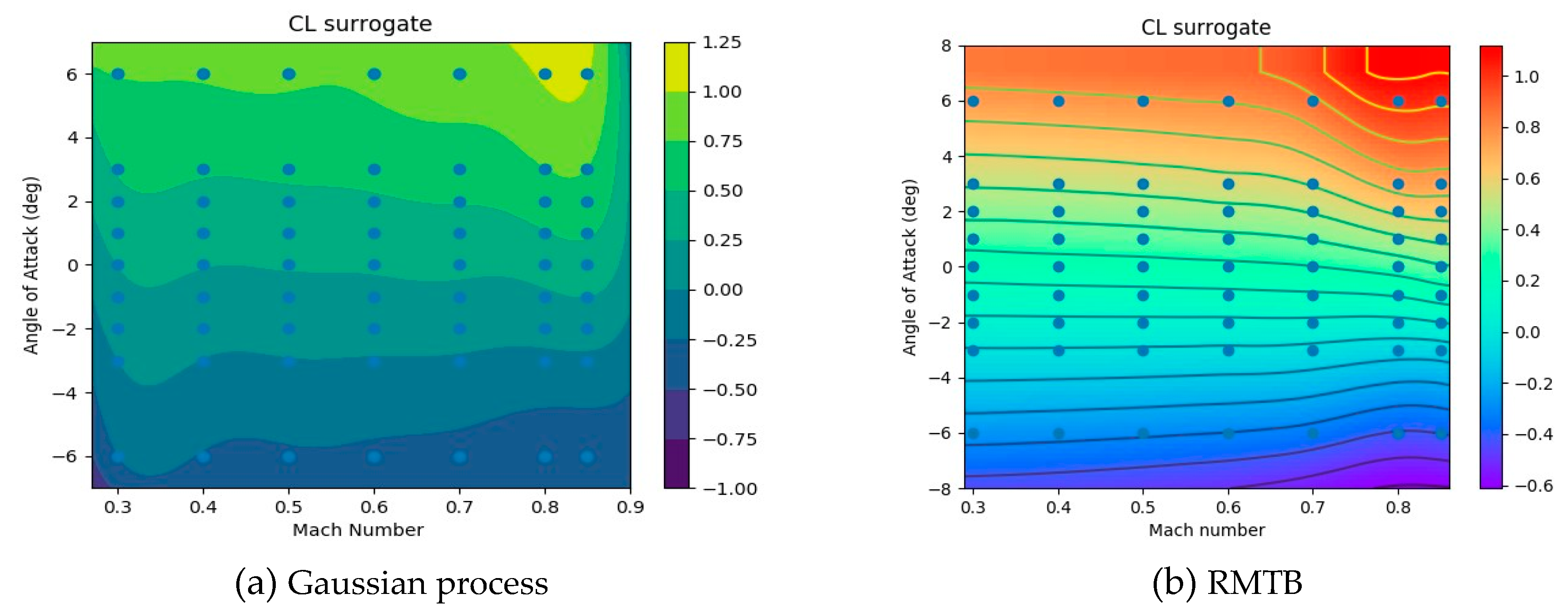
M = 0.3, the Mach number where compressibility effects are negligible. An additional SUAVE script was written to extract compressibility drag from SU2 and include it in the analysis as a surrogate. For the surrogate model, instead of the default Gaussian process surrogate model in SUAVE, the Surrogate Modeling Toolbox (SMT) developed by the MDO lab of the University of Michigan [
39] was integrated in SUAVE. The RMTB B-spline method was used to fit the data. The SMT-toolbox was chosen because of its superior fitting capabilities when compared to the default Gaussian process method with SUAVE. A comparison of the lift and compressibility drag coefficients between the two methods are shown in
Figure 6 and
Figure 7. From these figures, one can observe that the RMTB method presents much better flexibility to accurately fit both lift and drag compared to the Gaussian process.
The aerodynamic results that were calculated with SU2 were used to build up surrogates for SUAVE overall aircraft aerodynamic performance estimation.
Figure 8 shows the airframe geometry and an example CFD mesh of half of the SE²A-LR aircraft geometry. It is important to note that the effect of winglets is excluded in the present CFD analysis. Such a decision was made due to limitations in the definition of the FFD-box (see
Section 5) and to adequately compare planforms before and after the aerodynamic optimization. It is assumed that the winglet aerodynamic problem will be directly solved during the next design iteration and the wing optimal planform will be updated again.
A mesh convergence analysis has been performed to accurately capture the compressibility effect. The results of the drag coefficient sensitivity to mesh resolution at zero angle-of-attack and
M = 0.85 are shown in
Table 6. Here, an extrapolated value was estimated using the following procedure.
The computational domain volume is assumed as
where
is the number of cells and
is the average cell side length. Subsequently, the surface cell area is described as
It is assumed that, as long as it is proportional to, it is also proportional to. Therefore, an ideal can be estimated by approaching the number of cells to infinity.
From the mesh convergence analysis, 660,528 cells were used to combine accuracy and minimize the computational costs.
Figure 9 shows the aircraft pressure coefficient contours at the cruise conditions using this mesh. A surrogate model using the RMTB method was created for drag based on the SU2 analysis in order to evaluate the aircraft performance in SUAVE.
From this figure, one can observe that strong shock waves along the aircraft span on both the upper and power surfaces of the BWB aircraft, which results in large compressibility drag. Such behavior has not been captured by the low-fidelity analysis. In the low-fidelity analysis, a semi-empirical formulation was used to calculate drag due to compressibility. Although semi-empirical methods provide good accuracy without computational costs, they may have limitations when the analysis is done for an unconventional configuration. Consequently, the higher aircraft drag predicted by SU2 increased the fuel required to complete the mission by 24.1%. Therefore, the difference in fuel efficiency between the SE²A-LR, and B777 became equal to 10.6%, i.e., the new BWB aircraft has higher fuel consumption that Boeing 777.
Table 7 shows a modified comparison between the SE²A-LR aircraft and B777 weights and fuel efficiency while using the higher-fidelity analysis.
Appendix A presents details of the mission analysis using the results of the higher fidelity aerodynamic analysis.
5. Aerodynamic Shape Optimization
To mitigate losses that are created by compressibility drag, a discrete adjoint aerodynamic shape optimization using SU2 was performed. For the present optimization problem, the SLSQP algorithm available through the Python interface Scipy [
40] was used. Only a single-point optimization for an average cruise condition was considered. The objective function was to minimize the aircraft drag, subjected to geometric constraints for 10 selected sections along with the aircraft. A Free-From Deformation Box (FFD) with 15 × 11 × 2 (total of 330) control points was used to modify the geometry at every optimization iteration.
Table 8 shows the optimization problem statement and
Figure 10 shows the geometric representation of the FFD and constrained sections.
The lift coefficient constraint is based on an average lift coefficient during the cruise. The thicknesses of the initially selected airfoils satisfied the required volume for both passenger and fuel, however, it was found that such a choice was conservative. The reduction of maximum thickness by 20% still satisfies volume requirements for fuel and passengers (although it negatively influenced the structural weight). Therefore, the thickness constraints for the optimization were defined to avoid getting a thickness reduction of more than 20% when compared to the initial design. Finally, a constraint of leading-edge radii reduction not exceeding 20% was imposed to avoid the possibilities of sharp-edge sections generation.
Figure 11 shows a comparison between the initial and optimized designs. From this figure, one can observe that the shock wave strength was substantially reduced, which caused a reduction in inviscid drag by 77%. However, because the optimization has thickness constraints, shock waves have not been completely removed, so the compressibility drag is not equal to zero.
Figure 12 shows a comparison of lift distributions between initial and final designs and elliptical lift distribution. The results show that the optimized geometry approached elliptical lift distribution when compared to the initial design which has a significant portion of lift produced by the fuselage and a mid-span loaded wing. However, from the structural perspective, elliptical lift distribution does not give the benefits from the structural point of view. Qin et al. [
41] show that an elliptical/triangular lift distribution provides the best combination of minimum drag achievements and structural weight benefits. Present optimization has not captured this trend due to the absence of structural optimization coupling. Coupled aero-structural optimization will be performed during the next design iteration.
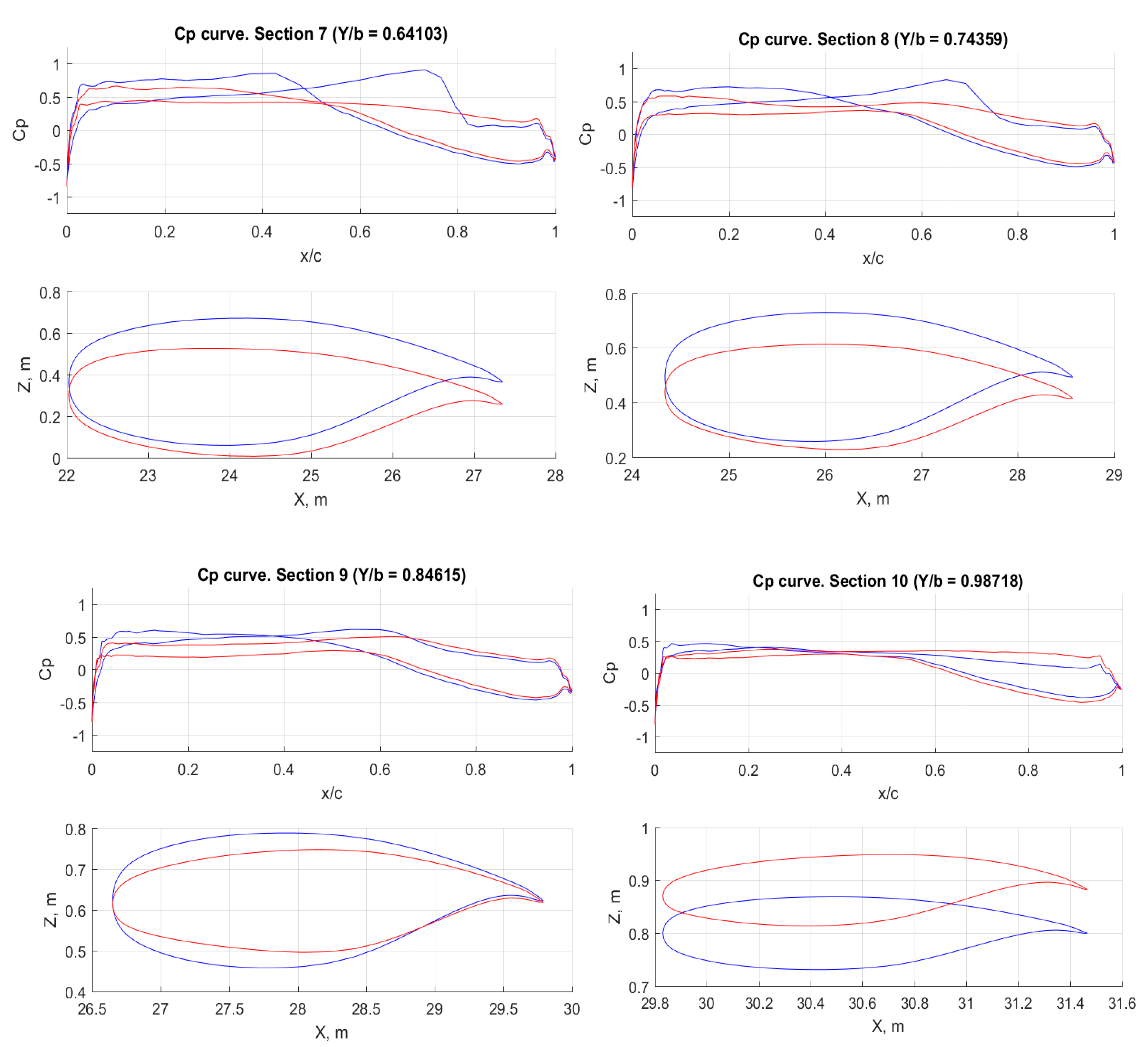
Figure 13 demonstrates the distribution of pressure coefficient along 10 control sections of the geometry. The blue lines show initial sections, while the red lines illustrate the modifications after optimization. From this figure, the smoothening of all the pressure distributions can be observed. Besides, three trends can be observed: first of all, the maximum thickness of the inboard sections has not been substantially reduced, although a 20% reduction of thickness was allowed for all sections. The airfoil maximum thickness moved towards the leading edge making the aft part thinner. On the other hand, more significant thickness reduction is observed towards the wingtip. Second, the optimized wing demonstrates a 1 deg washout and increase the flight angle-of attack from −1.68 deg to −0.82 deg to reduce the shock wave strength, but still satisfying the lift coefficient requirements. Finally, a minor increase in the wing dihedral is observed.
6. Validation of the Drag Estimation Method using the Mixed Fidelity Model
Because the Euler method is based on an inviscid flow assumption, its results lack the viscous drag. Although the lower fidelity method based on the flat plate analogy was used to compute the friction drag and add it to the inviscid drag of the Euler analysis, the accuracy of such a multi-fidelity method needs to be checked. For this purpose, a series of RANS analysis of the optimized geometry at the cruise Mach number of 0.85 at 35,000 ft for a fully turbulent wing was performed at different angles of attack. A mixed mesh that combines quadrilateral cells at the boundary layer and pyramid cells everywhere else was created while using Pointwise [
42] software package.
Figure 14 shows the mesh of half of the airplane. The mesh has seven-million cells, while the boundary layer was sized for Y+ of 1. SU2 was used for the Navier–Stokes equations solutions with the Spallart–Almaras turbulence model.
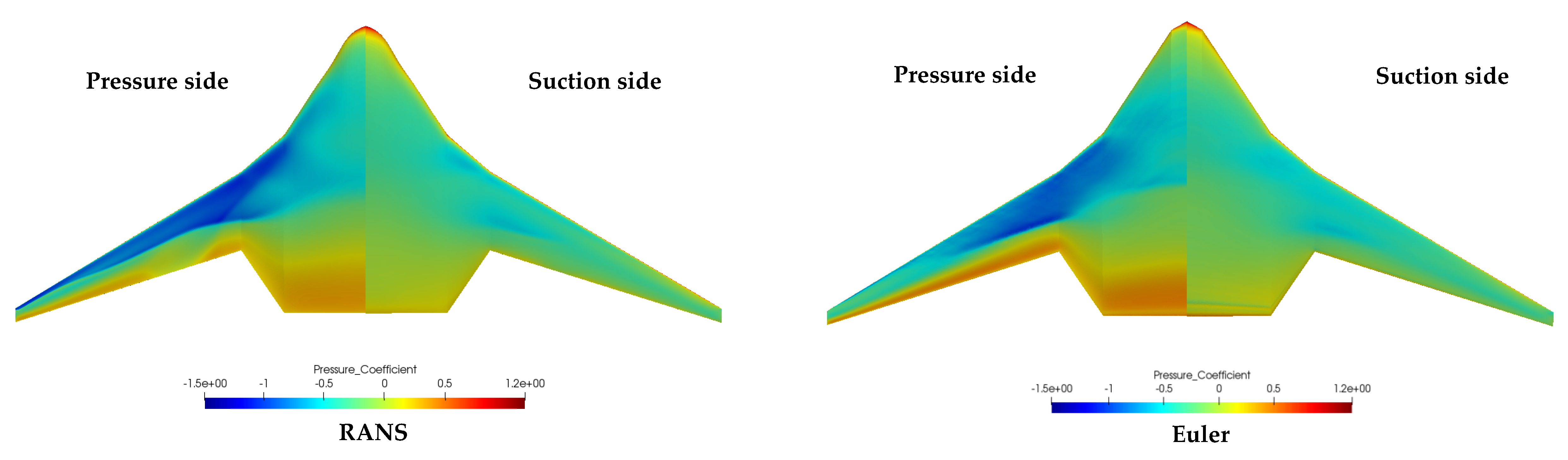
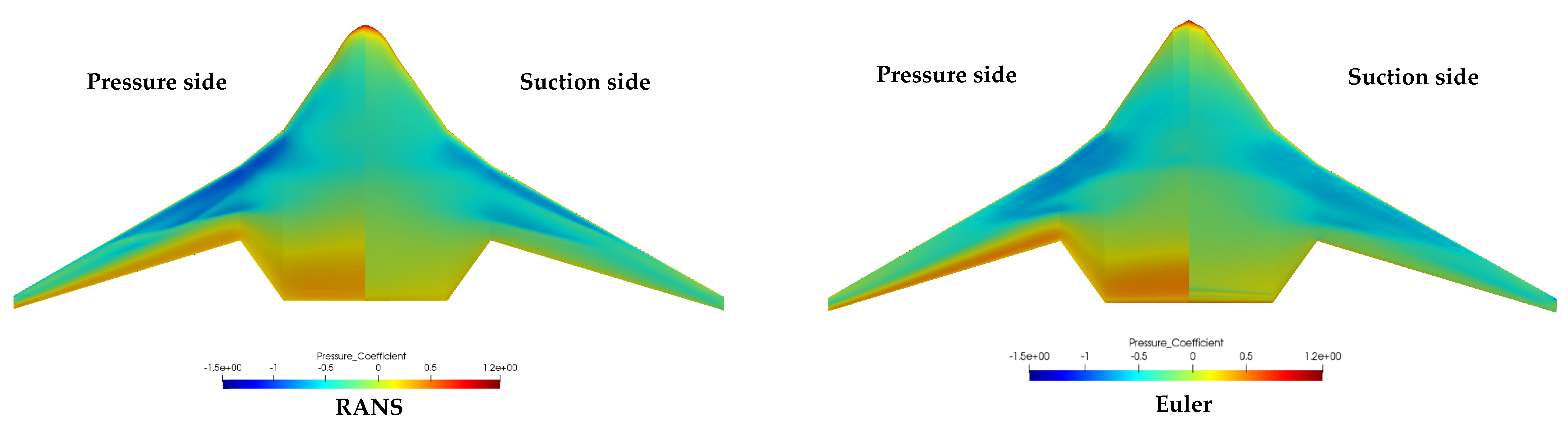
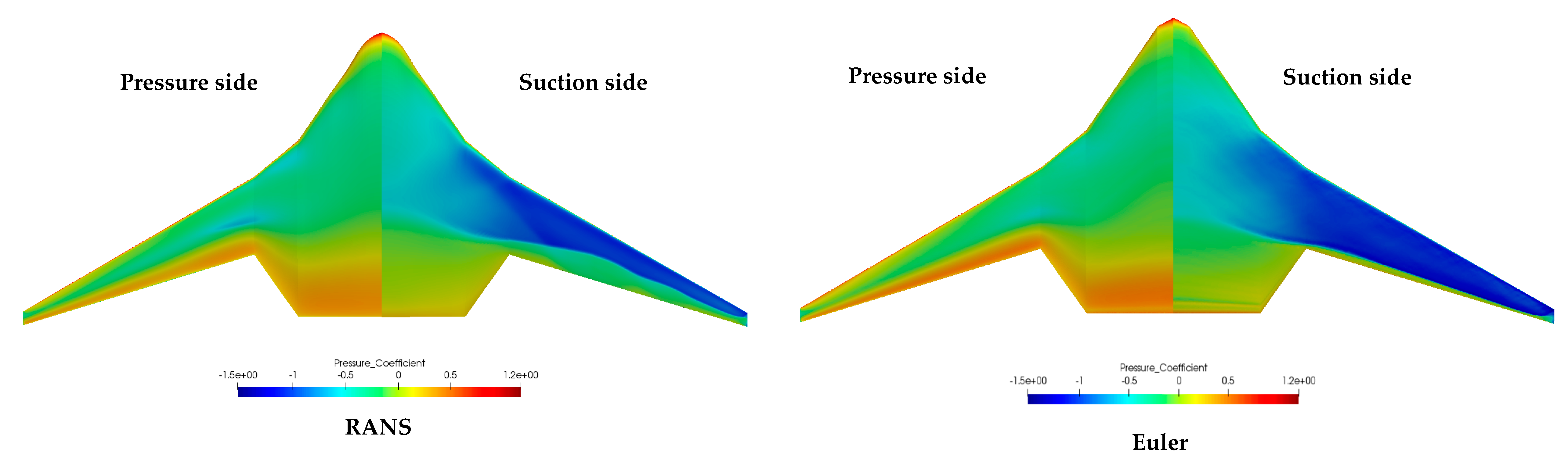
Appendix A gives a summary of the pressure coefficient comparison between the Euler and the RANS solutions.
Figure 15 shows a comparison of aerodynamic data between the RANS and the combined Euler and semi-empirical solutions.
The results show multiple trends. First, the RANS lift curve has a lower lift magnitude at a similar angle of attack when compared to the Euler solution. That is the cause of differences in pressure distribution and estimation of the shock wave strength. A similar trend was observed in [
43] for the lift curve, where the lift coefficients at low angles of attack were similar with 0.5 deg difference between the experimental data and Euler solutions. After the angle of attack of 1 deg, the RANS lift curve starts showing non-linear behavior due to the generation of strong shock waves on the wing suction side. Such a trend is also observed for Euler solutions, but the Euler solution also does not simulate shock-induced separation, which happens in the RANS case; therefore, the reduction in the lift is lower in Euler compared to RANS.The drag polar shows that at low lift coefficient, the drag coefficient of RANS matches well with the Euler solutions plus the friction drag from flat plate analogy. However, deviations after the lift coefficient of 0.2 starts appearing. There is a good match between Euler (and friction drag) and RANS solution in drag polar until the lift coefficient of 0.5, but the drag polar of RANS then rises more rapidly due to the shock-induced separation. A similar increase in drag happens for lift coefficients below -0.1. The range of the whole mission lift coefficients falls between 0.1 and 0.35, while the cruise segment is completed at lift coefficients between 0.12 and 0.2. For such a range, a combination of Euler results with the flat plate analogy shows sufficient accuracy for capturing the aircraft aerodynamics and estimating its mission performance.
7. Mission Performance Analysis of an Optimized Geometry
After a single-point optimization, the mission was calculated again to obtain modified results with the account of high-fidelity aerodynamics.
Appendix A shows this simulation results, while
Table 9 provides a comparison of relative changes among low/medium fidelity, high-fidelity analysis of the initial aircraft and optimized high-fidelity results with respect to B777 results
The results show substantial improvements in mission analysis. However, improvements that are caused by new technologies do not match the low-fidelity analysis. Fuel efficiency improvement does not exceed 61% for the analysis while using higher fidelity tools. In addition, maximum L/D reduced from 50.5 to 39.5, which also demonstrates an increase in aircraft total drag. This shows that higher fidelity analysis plays an important role in initial stages of design and it should not be avoided if the design considers unconventional configurations.
Although the results demonstrate substantial improvement in aircraft performances, there are still uncertainties in the results, which will be addressed in future works. Limitations of analysis are driven by the uncertainty of expected technological benefits and their real performance. It was assumed that 80% of the wing will be laminar. However, no additional power required for the suction system was considered in the current analysis. Moreover, the effects of surface irregularities, such as landing gear doors, access panels, windows, etc., have not been considered. They might substantially reduce the laminarization of the vehicle or require unacceptable power for the suction system. In addition, the suction system weight was not considered at the moment due to a lack of information regarding the power required to suck the boundary layer from the wing. Other technologies, such as active load alleviation, boundary layer ingestion, and advanced structure concepts, also lack any surrogate data, which will be developed later under this research program.
8. Conclusions
The present manuscript describes a multi-fidelity design approach to design a fuel-efficient BWB aircraft. Multiple novel technologies have been integrated at the conceptual design phase to increase the aircraft efficiency and minimize negative environmental impact: active flow control (boundary layer suction), active load alleviation, boundary layer ingestion, and new materials and structure concepts. The presented approach was used to design a long-range BWB aircraft.
A multi-fidelity approach has been used to increase design accuracy. The SUAVE aircraft design environment with the integration of novel technologies module was used for mission analysis, OpenVSP and Gmesh were used for geometry modeling and mesh generation, and AVL and SU2 were used for aerodynamic analysis. Euler equations CFD analysis was used to minimize the computational costs and capture transonic aerodynamic effects.
A low/medium fidelity approach (using AVL for CFD) has shown significant improvement in fuel efficiency of a potential long-range aircraft—almost 76% increase in fuel efficiency as compared to B777. However, mission analysis using SU2 demonstrated a substantial increase in drag due to compressibility that has not been captured by the lower fidelity analysis. A large increase in drag reduced fuel efficiency by 10.6% as compared to B777.
High-fidelity discrete-adjoint aerodynamic shape optimization using SU2 was performed to minimize the adverse effects of the wave drag. FFD approach was used to modify the aircraft geometry, and an SLSQP algorithm was used for optimization. The objective function was to reduce drag for an average cruise condition and geometric constraints of a maximum thickness not being less than 80% when compared to the initial design. The results showed a reduction of inviscid drag by 77% as compared to the initial configuration.
The validation of the combination of Euler surrogate data and the flat plate analogy was also performed and the results used in SUAVE were compared to RANS simulations for cruise conditions. The results show sufficient accuracy between two methods for low lift coefficients. In addition, the cruise segment is performed at similar low angles of attack, so the method is sufficiently accurate to simulate the flight mission.
A modified mission analysis with an optimized aircraft and higher fidelity aerodynamic analysis significantly improved the fuel efficiency as compared to the initial design: the fuel efficiency changed from +10.6% to −59.2% when compared to B777. However, an optimized solution did not match the lower fidelity analysis, which indicates the desire to introduce higher fidelity tools as early as possible in the conceptual design stage to have more accuracy during the design of unconventional aircraft configurations.
Future work will focus on multiple tasks. First, a new design iteration with focus on stability and control, weights and balance, and system layouts will be performed. Second, the refinement of drag coefficient estimation needs to be performed: RANS analysis with embedded porous wall boundary condition responsible for the boundary layer suction will be performed, and new surrogate drag values will be obtained and used in SUAVE to more accurately determine potential fuel savings. In addition, surrogate models of structural weigh reduction, boundary layer ingestion, and active load alleviation will be implemented in SUAVE to more accurately estimate the potential benefits of novel technologies. Finally, an improved technique for the FFD definition will be implemented in SU2 to more uniformly distribute control points along with the aircraft geometry and increase the accuracy and flexibility of the shape optimization.
The present manuscript only covers very preliminary results based on the methods developed in the first stage of the project. The major concerns include the actual capabilities of investigated technologies. Changes in technology assumptions may significantly affect aircraft performance and fuel savings. The design will face multiple iterations with progressively increasing levels of design and analysis accuracy, fidelity, and depth.
Author Contributions
Conceptualization, S.K., Y.L., A.E.; methodology, S.K., Y.L., A.E.; software, S.K., Y.L.; validation, S.K.; formal analysis, S.K.; investigation, S.K.; writing—original draft preparation, S.K., Y.L.; writing—review and editing, A.E.; visualization, S.K.; supervision, A.E.; funding acquisition, A.E. All authors have read and agreed to the published version of the manuscript.
Funding
We would like to acknowledge the funding by the Deutsche Forschungsgemeinschaft (DFG, German Research Foundation) under Germany’s Excellence Strategy—EXC 2163/1-Sustainable and Energy Efficient Aviation—Project-ID 390881007. Furthermore, we acknowledge support by the Open Access Publication Funds of the Technische Universität Braunschweig.
Conflicts of Interest
The authors declare no conflict of interest.
Appendix A. Summary of SUAVE Analysis for All Analyzed Cases
Table A1.
Weight break-down of B777 calculated using SUAVE.
Table A1.
Weight break-down of B777 calculated using SUAVE.
| Mass Items | Unit | Value |
|---|
| Maximum Take-off Weight (MTOW) | kg | 347,452.0 |
| Operating Weight Empty (OWE) | kg | 157,432 |
| Wing | kg | 53,959 |
| Fuselage | kg | 29,032 |
| Empennage | kg | 7896.0 |
| Propulsion group | kg | 28,530 |
| Landing gear | kg | 13,898 |
Systems (including opt. and furn.)
Breakdown of system mass | kg | 24,117 |
| Control systems | kg | 2691 |
| APU | kg | 953 |
| Hydraulics | kg | 1386 |
| Instruments | kg | 363 |
| Avionics | kg | 408 |
| Optionals | kg | 3810 |
| Electrical | kg | 1769 |
| Air conditioner | kg | 2041 |
| Furnish | kg | 10,696 |
Figure A1.
Aerodynamic performance of B777.
Figure A1.
Aerodynamic performance of B777.
Figure A2.
Mission performance of B777.
Figure A2.
Mission performance of B777.
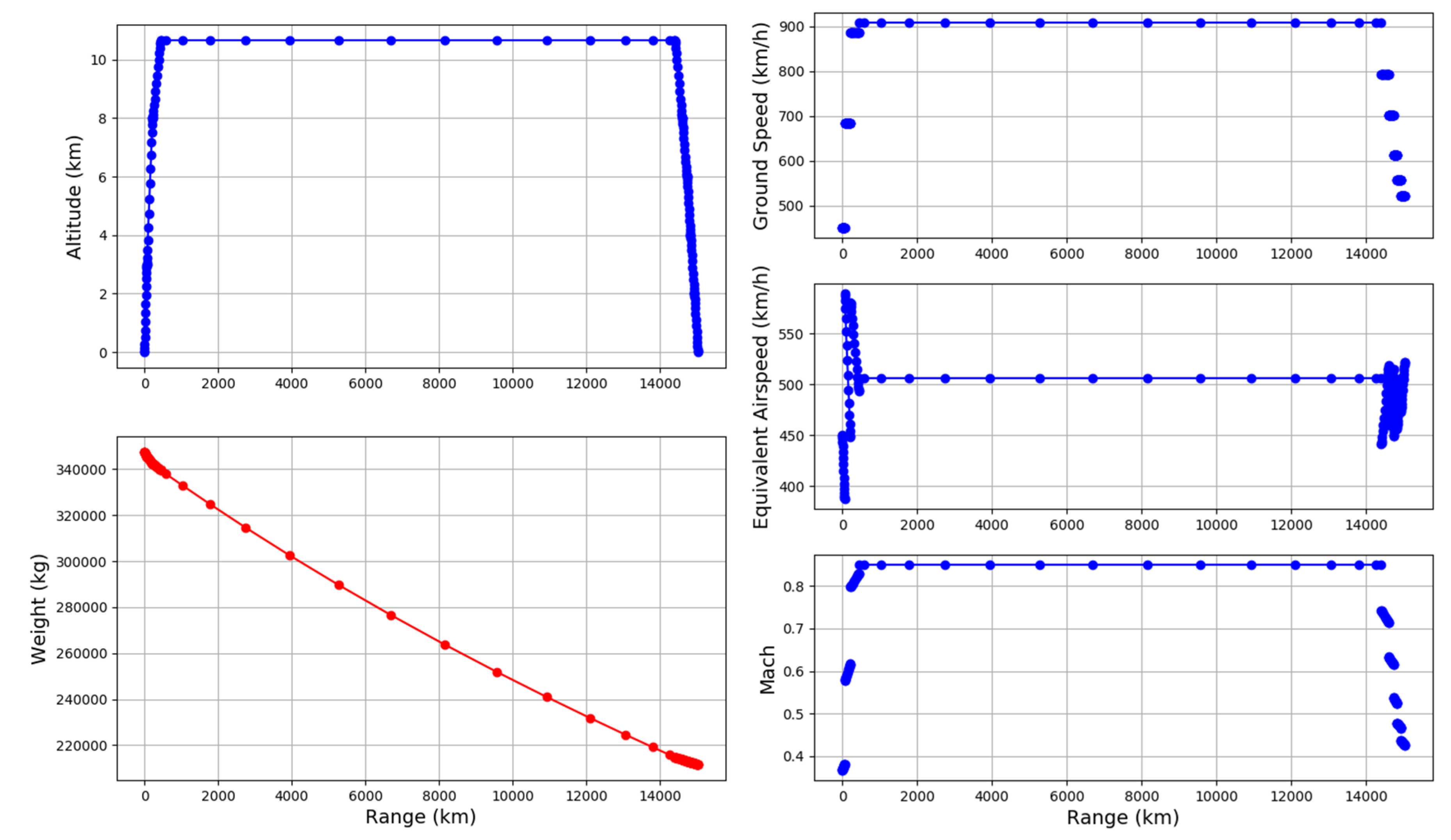
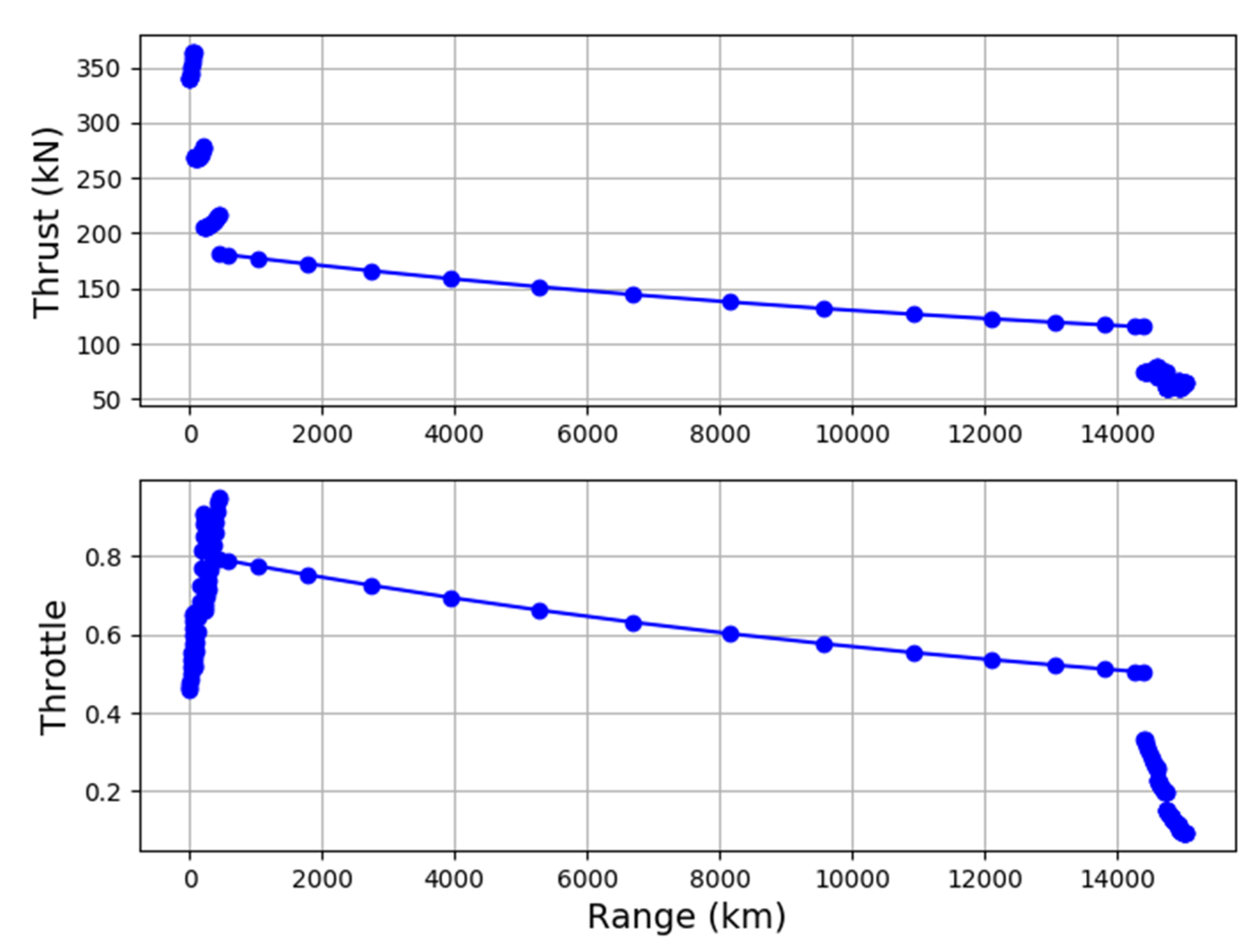
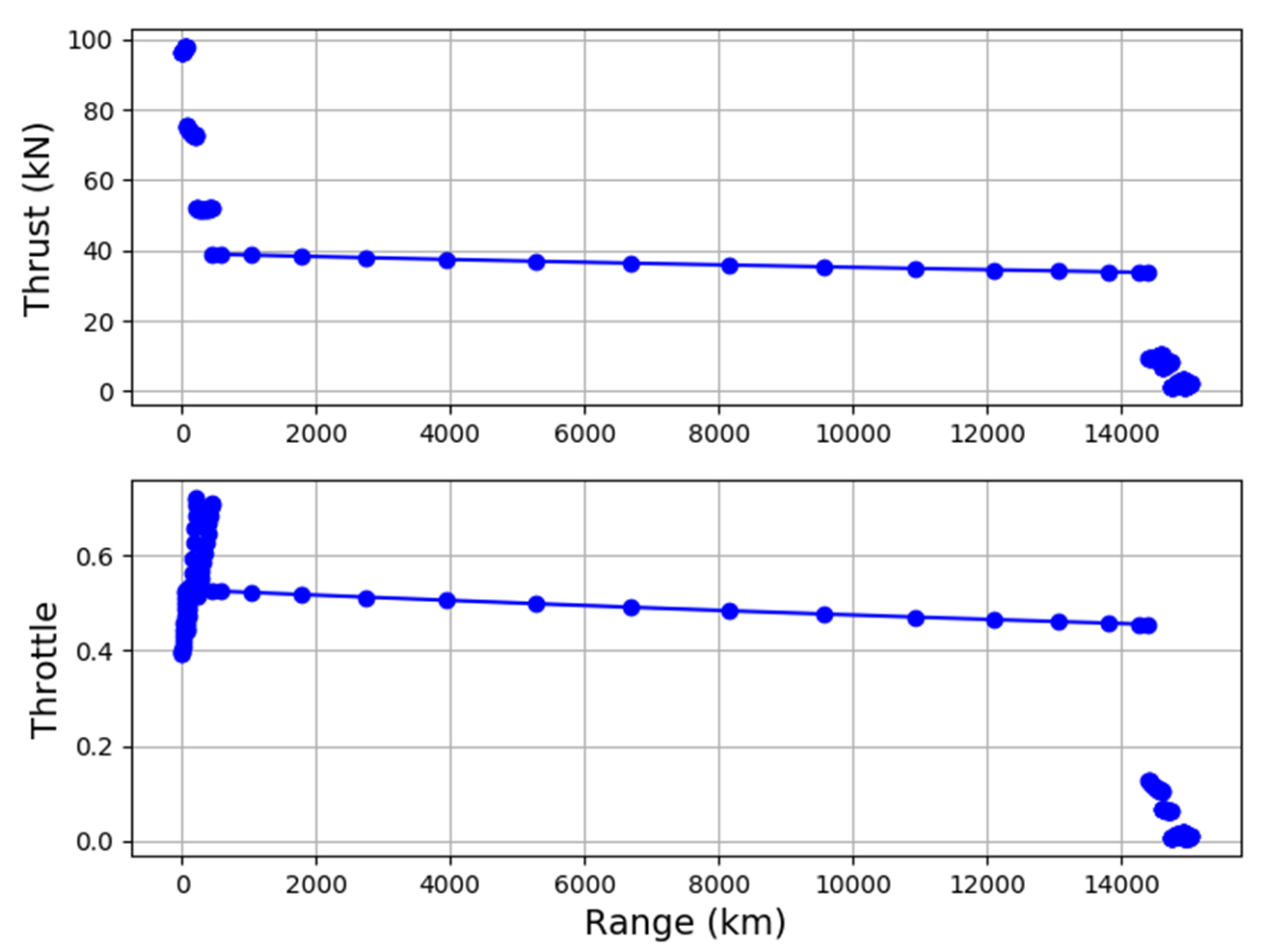
Figure A3.
Thrust and throttle settings of SE²A-LR.
Figure A3.
Thrust and throttle settings of SE²A-LR.
Table A2.
Initial Weight break-down of SE²A-LR calculated using SUAVE.
Table A2.
Initial Weight break-down of SE²A-LR calculated using SUAVE.
| Mass Items | Unit | Value |
|---|
| Operating Weight Empty (OWE) | kg | 82,484 |
| Wing | kg | 10,930 |
| Fuselage | kg | 32,441 |
| Propulsion group | kg | 11,057 |
| Landing gear | kg | 5699 |
Systems (including opt. and furn.)
Breakdown of system mass | kg | 22,357 |
| Control systems | kg | 1489 |
| APU | kg | 953 |
| Hydraulics | kg | 828 |
| Instruments | kg | 363 |
| Avionics | kg | 408 |
| Optionals | kg | 3810 |
| Electrical | kg | 1769 |
| Air conditioner | kg | 2041 |
| Furnish | kg | 10,696 |
Figure A4.
Aerodynamic performance of SE²A-LR.
Figure A4.
Aerodynamic performance of SE²A-LR.
Figure A5.
Mission performance of SE²A-LR.
Figure A5.
Mission performance of SE²A-LR.
Figure A6.
Thrust and throttle settings of SE²A-LR.
Figure A6.
Thrust and throttle settings of SE²A-LR.
Figure A7.
Aerodynamic performance of SE²A-LR calculated using SUAVE for higher-fidelity analysis.
Figure A7.
Aerodynamic performance of SE²A-LR calculated using SUAVE for higher-fidelity analysis.
Figure A8.
Mission performance of SE²A-LR.
Figure A8.
Mission performance of SE²A-LR.
Figure A9.
Thrust and throttle settings of SE²A-LR.
Figure A9.
Thrust and throttle settings of SE²A-LR.
Table A3.
Weight break-down of SE²A-LR calculated using SUAVE after optimization.
Table A3.
Weight break-down of SE²A-LR calculated using SUAVE after optimization.
| Mass Items | Unit | Value |
|---|
| Operating Weight Empty (OWE) | kg | 88,318 |
| Wing | kg | 12,180 |
| Fuselage | kg | 33,412 |
| Propulsion group | kg | 13,594 |
| Landing gear | kg | 6774 |
Systems (including opt. and furn.)
Breakdown of system mass | kg | 22,357 |
| Control systems | kg | 1489 |
| APU | kg | 953 |
| Hydraulics | kg | 828 |
| Instruments | kg | 363 |
| Avionics | kg | 408 |
| Optionals | kg | 3810 |
| Electrical | kg | 1769 |
| Air conditioner | kg | 2041 |
| Furnish | kg | 10,696 |
Figure A10.
Aerodynamic performance of SE²A-LR.
Figure A10.
Aerodynamic performance of SE²A-LR.
Figure A11.
Mission performance of SE²A-LR.
Figure A11.
Mission performance of SE²A-LR.
Figure A12.
Thrust and throttle settings of SE²A-LR.
Figure A12.
Thrust and throttle settings of SE²A-LR.
Figure A13.
Pressure coefficients for RANS and Euler simulations at AoA = −2 deg.
Figure A13.
Pressure coefficients for RANS and Euler simulations at AoA = −2 deg.
Figure A14.
Pressure coefficients for RANS and Euler simulations at AoA = -1 deg.
Figure A14.
Pressure coefficients for RANS and Euler simulations at AoA = -1 deg.
Figure A15.
Pressure coefficients for RANS and Euler simulations at AoA = 0 deg.
Figure A15.
Pressure coefficients for RANS and Euler simulations at AoA = 0 deg.
Figure A16.
Pressure coefficients for RANS and Euler simulations at AoA = 1 deg.
Figure A16.
Pressure coefficients for RANS and Euler simulations at AoA = 1 deg.
Figure A17.
Pressure coefficients for RANS and Euler simulations at AoA = 2 deg.
Figure A17.
Pressure coefficients for RANS and Euler simulations at AoA = 2 deg.
References
- Flightpath 2050-Europe’s Vision for Aviation: Advisory Council for Aeronautics Research in Europe; EUROPEAN COMMISSION: Brussels, Belgium, 2011.
- Liu, Y.; Elham, A.; Horst, P.; Hepperle, M. Exploring Vehicle Level Benefits of Revolutionary Technology Progress via Aircraft Design and Optimization. Energies 2018, 11, 166. [Google Scholar] [CrossRef]
- Liebeck, R.H. Design of the Blended Wing Body Subsonic Transport. J. Aircr. 2004, 41, 10–25. [Google Scholar] [CrossRef]
- Okonkwo, P.; Smith, H. Review of evolving trends in blended wing body aircraft design. Prog. Aerosp. Sci. 2016, 82, 1–23. [Google Scholar] [CrossRef]
- Xu, J.; Kroo, I. Aircraft Design with Active Load Alleviation and Natural Laminar Flow. J. Aircr. 2014, 51, 1532–1545. [Google Scholar] [CrossRef]
- Greitzer, E.M.; Bonnefoy, P.A.; DelaRosaBlanco, E.; Dorbian, C.S.; Drela, M.; Hall, D.K.; Hansman, R.J.; Hileman, J.I.; Liebeck, R.H.; Lovegren, J.; et al. N+ 3 Aircraft Concept Designs and Trade Studies. Volume 2: Appendices-Design Methodologies for Aerodynamics, Structures, Weight, and Thermodynamic Cycles; NASA/CR—2010-216794/VOL2; NASA: Washington, DC, USA, 2010.
- Greitzer, E.M.; Bonnefoy, P.A.; DelaRosaBlanco, E.; Dorbian, C.S.; Drela, M.; Hall, D.K.; Hansman, R.J.; Hileman, J.I.; Liebeck, R.H.; Levegren, J.; et al. N+ 3 Aircraft Concept Designs and Trade Studies; NASA: Washington, DC, USA, 2010; Volume 1.
- Bradley, M.K.; Droney, C.K. Subsonic Ultra-Green Aircraft Research Phase II: N+ 4 Advanced Concept Development: NASA/CR-2012-217556; NASA: Washington, DC, USA, 2012. [Google Scholar]
- Saeed, T.I.; Graham, W.R. Design Study for a Laminar-Flying-Wing Aircraft. J. Aircr. 2015, 52, 1373–1385. [Google Scholar] [CrossRef]
- Beck, N.; Landa, T.; Seitz, A.; Boermans, L.; Liu, Y.; Radespiel, R. Drag Reduction by Laminar Flow Control. Energies 2018, 11, 252. [Google Scholar] [CrossRef]
- Risse, K.; Stumpf, E. Conceptual Aircraft Design including Hybrid Laminar Flow Control. CEAS Aeronaut. J. 2014, 5, 333–343. [Google Scholar] [CrossRef]
- Bussemaker, J.H. Wing Optimization with Active Load Control. Master’s Thesis, Faculty of Aerospace Engineering, Flight Performance, and Propulsion, TU Delft, Delft, The Netherlands, 2018. [Google Scholar]
- Xu, J. Aircraft Design with Active Load Alleviation and Natural laminar Flow. Ph.D. Thesis, Department of Aeronautics & Astronautics, Stanford University, Stanford, CA, USA, 2014. [Google Scholar]
- Rossow, C.-C.; von Geyr, H.; Hepperle, M. The 1g-Wing, Visionary Concept or Naive Solution? DLR-IB-AS-BS-2016-121; DLRInterner Bericht: Braunschweig, Germany, 2016. [Google Scholar]
- Liu, X.; Sun, Q. Gust Load Alleviation with Robust Control for a Flexible Wing, Shock and Vibration; ID 1060574; Hindawi Publishing Corporation: London, UK, 2016; Volume 2016. [Google Scholar] [CrossRef][Green Version]
- Ying, B.; Changchum, X. Gust load alleviation wind tunnel tests of a large-aspect-ratio flexible wing with piezoelectric control. Chin. J. Aeronaut. 2017, 30, 292–309. [Google Scholar]
- Blumenthal, B.; Elmiligui, A.; Geiselhart, K.; Campbell, R. Computational Investigation of a Boundary-Layer-Ingestion Propulsion System. J. Aircr. 2018, 55, 1141–1153. [Google Scholar] [CrossRef]
- Uranga, A.; Drela, M.; Greitzer, E.; Hall, D.; Tichener, N.; Lieu, M.; Siu, N.; Casses, C.; Huang, A. Boundary Layer Ingestion Benefit of the D8 Transport Aircraft. AIAA J. 2017, 55, 3693–3708. [Google Scholar] [CrossRef]
- Zhang, J.; Kang, W.; Yang, L. Aeroynamic benefits of boundary layer ingestion for distributed propulsion configuration. Aircr. Eng. Aerosp. Technol. 2019, 91, 1285–1294. [Google Scholar] [CrossRef]
- Gray, J.; Martins, J. Coupled Aeropropulsive Design Optimization of Boundary Layer Ingestion Propulsor. Aeronaut. J. R. Aeronaut. Soc. 2018, 123, 1–19. [Google Scholar]
- Budziszewski, N.; Friedrichs, J. Modelling of a Boundary Layer Ingesting Propulsor. Energies 2018, 21, 708. [Google Scholar] [CrossRef]
- Giesecke, D.; Lehmler, M.; Friedrichs, J.; Blinstrub, J.; Bertsch, L.; Heinze, W. Evaluation of ultra-high bypass ratio engines for an over-wing aircraft configuration. GPPS J. 2018. [Google Scholar] [CrossRef]
- Bishara, M.; Horst, P.; Madhusoodanan, H.; Brod, M.; Daum, B.; Rolfes, R. A Structural Design Concept for a Multi-Shell Blended Wing Body with Laminar Flow Control. Energies 2018, 11, 383. [Google Scholar] [CrossRef]
- Lukaczyk, T.W.; Wendorff, A.D.; Colonno, M.; Economon, T.D.; Alonso, J.J.; Orra, T.H.; Ilario, C. SUAVE: An Open-Source Environment for Multi-Fidelity Conceptual Vehicle Design. In Proceedings of the 16th AIAA/ISSMO Multidisciplinary Analysis and Optimization Conference, American Institute of Aeronautics and Astronautics, Dallas, TX, USA, 22–25 June 2015. [Google Scholar]
- Economon, T.D.; Palacios, F.; Copeland, S.R.; Lukaczyk, T.W.; Alonso, J.J. SU2: An Open-Source Suite for Multiphysics Simulation and Design. AIAA J. 2016, 54, 828–846. [Google Scholar] [CrossRef]
- Fredericks, W.; Antclif, K.; Costa, G.; Deshpande, N.; Moore, M.; Miguel, E.S.; Snyder, A. Aircraft Conceptual Design Using Vehicle Sketch Pad. In Proceedings of the 48th AIAA Aerospace Sciences Meeting including the New Horizons Forum and Aerospace Exposition, Orlando, FL, USA, 4–7 January 2010. [Google Scholar]
- Abramson, M.A.; Audet, C.; Couture, G.; Dennis John, E., Jr.; Le Digabel, S.; Tribes, C. The NOMAD Project. 2014. Available online: http://www.gerad.ca/nomad (accessed on 6 June 2020).
- van Dommelen, J.; Vos, R. Conceptual Design and Analysis of a Blended-Wing-Body Aircraft. SAGE J. 2014. [Google Scholar] [CrossRef]
- Drela, M.; Youngeren, H. AVL-Athena Vortex Lattice code. MIT Aero Astro. Proc IMechE Part G J. Aerosp. Eng. 2014, 228, 2452–2474. [Google Scholar]
- Safran CFM 56-7B22 Engine Specifications. Available online: https://www.safran-aircraft-engines.com/commercial-engines/single-aisle-commercial-jets/cfm56/cfm56-7b (accessed on 6 June 2020).
- Botero, E.M.; Wendorff, A.; MacDonald, T.; Variyar, A.; Vegh, J.M.; Lukaczyk, T.W.; Alonso, J.J.; Orra, T.H.; da Silva, C.I. SUAVE: An Open-Source Environment for Conceptual Vehicle Design and Optimization. In Proceedings of the 54th AIAA Aerospace Sciences Meeting, American Institute of Aeronautics and Astronautics, San Diego, CA, USA, 4–8 January 2016. [Google Scholar]
- MacDonald, T.; Botero, E.; Vegh, J.M.; Variyar, A.; Alonso, J.J.; Orra, T.H.; da Silva, C.R.I. SUAVE: An Open-Source Environment Enabling Unconventional Vehicle Designs through Higher Fidelity. In Proceedings of the 55th AIAA Aerospace Sciences Meeting, American Institute of Aeronautics and Astronautics, Grapevine, TX, USA, 9–13 January 2017. [Google Scholar]
- MacDonald, T.; Clarke, M.; Botero, E.M.; Vegh, J.M.; Alonso, J.J. SUAVE: An Open-Source Environment Enabling Multi-Fidelity Vehicle Optimization. In Proceedings of the 18th AIAA/ISSMO Multidisciplinary Analysis and Optimization Conference, Denver, CO, USA, 5–9 June 2017. [Google Scholar]
- Chen, Z.; Zhang, M.; Chen, Y.; Sang, W.; Tan, Z.; Li, D.; Zhang, B. Assessment on critical technologies for conceptual design of blended-wing-body civil aircraft. Chin. J. Aeronaut. 2019, 32, 1797–1827. [Google Scholar] [CrossRef]
- Kozek, M.; Schirrer, A. Modeling and Control for a Blended Wing Body Aircraft; Springer International Publishing: Berlin, Germany, 2015; ISBN 978-3-319-10791-2. [Google Scholar]
- Peifeng, L.; Binqian, Z.; Yingchun, C.; Changsheng, Y.; Yu, L. Aerodynamic Design Methodology for Blended Wing Body Transport. Chin. J. Aeronaut. 2012, 25, 508–516. [Google Scholar]
- Palacios, F.; Economon, T.D.; Aranake, A.; Copeland, S.R.; Lonkar, A.K.; Lukaczyk, T.W.; Manosalvas, D.E.; Naik, K.R.; Padron, S.; Tracey, B.; et al. Stanford University Unstructured (SU2): Analysis and Design Technology for Turbulent Flows. In Proceedings of the 52nd Aerospace Sciences Meeting, American Institute of Aeronautics and Astronautics, Harbor, MD, USA, 13–17 January 2014. [Google Scholar]
- Gudmundsson, S. General Aviation Aircraft Design: Applied Methods and Procedures; Butterworth-Heinemann: Oxford, UK, 2013; ISBN 0123973295. [Google Scholar]
- Bouhlel, M.A.; Hwang, J.T.; Bartoli, N.; Lafage, R.; Morlier, J.; Martins, J.R.R.A. A Python surrogate modeling framework with derivatives. Adv. Eng. Softw. 2019, 135, 102662. [Google Scholar] [CrossRef]
- Pauli, V.; Ralf, G.; Travis, E.O.; Matt, H.; Tyler, R.; David, C.; Evgeni, B.; Pearu, P.; Warren, W.; Jonathan, B.; et al. SciPy 1.0: Fundamental Algorithms for Scientific Computing in Python. Nat. Methods 2020, in press. [Google Scholar]
- Qin, N.; Vavalle, A.; le Moigne, A.; Laban, M.; Hackett, K.; Weinerfeit, P. Aerodynamic Studies for Blended Wing Body Aircraft. In Proceedings of the 9th AiAA/ISSMO Symposium on Multidisciplinary Analysis and Optimization, Atlanta, GA, USA, 4–6 September 2002. [Google Scholar]
- Pointwise Mesh Generation Software. Available online: https://www.pointwise.com/ (accessed on 6 June 2020).
- Hicks, R.; Cliff, S.; Melton, J.; Langhi, R.; Goodsell, A.; Robertson, D.; Moyer, S. Euler and Potential Experiment/CFD Correlations for a Transport and Two Delta-Wing Configurations, NASA Technical Memorandum 102208; NASA: Washington, DC, USA, 1990.
Figure 1.
Schematic views of the active suction system [
10].
Figure 1.
Schematic views of the active suction system [
10].
Figure 2.
Three-dimensional (3D) view of the initial reference long-range blended wing body (BWB) aircraft.
Figure 2.
Three-dimensional (3D) view of the initial reference long-range blended wing body (BWB) aircraft.
Figure 3.
Geometric comparison between long range aircraft SE²A-LR and B777 outer wings planforms [
2].
Figure 3.
Geometric comparison between long range aircraft SE²A-LR and B777 outer wings planforms [
2].
Figure 4.
Summary of maximum L/D for various types of aircraft [
32].
Figure 4.
Summary of maximum L/D for various types of aircraft [
32].
Figure 5.
Sequential build-up from Stanford University Aerospace Vehicle Environment (SUAVE) geometry and to SU2 CFD analysis.
Figure 5.
Sequential build-up from Stanford University Aerospace Vehicle Environment (SUAVE) geometry and to SU2 CFD analysis.
Figure 6.
Comparison between the RMTB and Gaussian process surrogates for the compressibility drag coefficient.
Figure 6.
Comparison between the RMTB and Gaussian process surrogates for the compressibility drag coefficient.
Figure 7.
Comparison between the RMTB and Gaussian process surrogates for the compressibility drag coefficient.
Figure 7.
Comparison between the RMTB and Gaussian process surrogates for the compressibility drag coefficient.
Figure 8.
Airframe geometry of SE²A-LR aircraft visualized in OpenVSP.
Figure 8.
Airframe geometry of SE²A-LR aircraft visualized in OpenVSP.
Figure 9.
Pressure coefficient contours of lower (left) and upper (right) aircraft surfaces. (α = 0°, M = 0.85).
Figure 9.
Pressure coefficient contours of lower (left) and upper (right) aircraft surfaces. (α = 0°, M = 0.85).
Figure 10.
Free-Form Deformation (FFD) Box (red) and control sections (blue) of the SE²A-LR aircraft geometry.
Figure 10.
Free-Form Deformation (FFD) Box (red) and control sections (blue) of the SE²A-LR aircraft geometry.
Figure 11.
Pressure coefficient contours of the upper aircraft surfaces for initial and optimized configurations.
Figure 11.
Pressure coefficient contours of the upper aircraft surfaces for initial and optimized configurations.
Figure 12.
Comparison of lift distribution between initial and optimized designs.
Figure 12.
Comparison of lift distribution between initial and optimized designs.
Figure 13.
Pressure coefficient and geometry sections. Blue curves represent the initial design and red curves represent the optimized design.
Figure 13.
Pressure coefficient and geometry sections. Blue curves represent the initial design and red curves represent the optimized design.
Figure 14.
CFD mesh for the RANS simulation.
Figure 14.
CFD mesh for the RANS simulation.
Figure 15.
Aerodynamic performance comparison between RANS and Euler with the flat plate analogy for the skin friction drag.
Figure 15.
Aerodynamic performance comparison between RANS and Euler with the flat plate analogy for the skin friction drag.
Table 1.
Top-level aircraft requirements of reference long-range aircraft Sustainable and Energy Efficient Aviation-LR (SE²A-LR).
Table 1.
Top-level aircraft requirements of reference long-range aircraft Sustainable and Energy Efficient Aviation-LR (SE²A-LR).
| Parameter | Unit | Value |
|---|
| Design range | NM | 8099 |
| Design passenger number | - | 300 |
| Cruise Mach number | - | 0.85 |
| Maximum Mach number | - | 0.92 |
| Cruise altitude | m | 10,600 |
| Take-off field length (TOFL) | m | <2200 |
| Landing distance | m | <1966 |
Table 2.
A summary of new airframe technologies applied to reference long-range aircraft SE²A-LR.
Table 2.
A summary of new airframe technologies applied to reference long-range aircraft SE²A-LR.
| SE²A Technology | Assumption |
|---|
| Active Laminar Flow Control | 80% of the aircraft area is laminarized |
| Advanced structures | 20% structure weight reduction |
| Active Load Alleviation | Limit load factor of 1.5 |
| Boundary layer ingestion | 5% improvement in propulsive efficiency |
Table 3.
Wing and vertical tail geometric properties.
Table 3.
Wing and vertical tail geometric properties.
| Geometric Parameter | Wing | Winglet |
|---|
| Span (m) | 57.80 | 3.00 |
| AR (m) | 7.40 | 2.00 |
| Taper ratio (m) | 0.065 | 1.00 |
| Root chord (m) | 30.60 | 1.5 |
| Quarter chord outer wing sweep (deg) | 20.00 | 30.00 |
Table 4.
Safran CFM 56-7B22 engine specifications [
30].
Table 4.
Safran CFM 56-7B22 engine specifications [
30].
| Engine Specifications | CFM 56-7B22 |
|---|
| Length (cm) | 250.8 |
| Width (cm) | 211.8 |
| Height (cm) | 182.9 |
| Dry weight (kg) | 2386.0 |
| Take-off thrust (kN) | 91600 |
| Take-off Thrust-specific fuel consumption (g/kN/s) | 10.1 |
Table 5.
Comparison of key aircraft parameters of reference long-range aircraft SE²A-LR and B777.
Table 5.
Comparison of key aircraft parameters of reference long-range aircraft SE²A-LR and B777.
| Parameter | SE²A-LR (In-House Tool) | SE²A-LR (SUAVE) | B777 | Relative Change Wrt B777 (%) |
|---|
| MTOW (kg) | 132,268.0 | 144,308.0 | 347,452.0 | −58.5 |
| OWE (kg) | 78,472.0 | 82,484.0 | 145,150.0 | −44.2 |
| L/Dmax | 45.5 | 48.0 | 21.0 | 127.0 |
| Cruise average L/D | 38.33 | 34.0 | 18.5 | 83.8 |
| Block fuel (kg) | 24,623.0 | 28,824.0 | 109,290.0 | −73.6 |
| Sea level static thrust (kN) | 400.0 | 442.3 | 1026.0 | −56.9 |
| Fuel Efficiency (kg/seat/100 km) | 0.55 | 0.64 | 2.72 | −76.5 |
Table 6.
Mesh convergence study for the cruise configuration in SU2 (α = 0 deg, M = 0.85).
Table 6.
Mesh convergence study for the cruise configuration in SU2 (α = 0 deg, M = 0.85).
| Mesh Number | Cell | CD | Error (%) |
|---|
| 1 | 343,612 | 0.01733 | 9.02 |
| 2 | 660,528 | 0.01673 | 5.25 |
| 3 | 835,000 | 0.01670 | 5.03 |
| 4 | 1,012,683 | 0.01665 | 4.72 |
| Extrapolation | ∞ | 0.01590 | 0.00 |
Table 7.
Comparison of key aircraft parameters of reference long range aircraft SE²A-LR and B777 using high-fidelity analysis.
Table 7.
Comparison of key aircraft parameters of reference long range aircraft SE²A-LR and B777 using high-fidelity analysis.
| Parameter | SE²A-LR (SUAVE-SU2) | B777 | Relative Change (%) |
|---|
| MTOW (kg) | 255,859.0 | 347,452.0 | −26.4 |
| OWE (kg) | 87,170.0 | 145,150.0 | −39.9 |
| L/Dmax | 43.0 | 21.0 | 104.8 |
| Cruise average L/D | 5.0 | 18.5 | −71.0 |
| Block fuel (kg) | 135,681.0 | 109,290.0 | 24.1 |
| Fuel Efficiency (kg/seat/100 km) | 3.01 | 2.72 | 10.6 |
Table 8.
Objective function definition.
Table 8.
Objective function definition.
| | Function/Variable | Description | Quantity |
|---|
| minimize | | Drag coefficient | |
| With respect to | | FFD control point z-coordinate | 330 |
| Subject to | | Lift coefficient constraint | 1 |
| | | Max thickness constraint for a given section | 10 |
| | | Leading-edge radius constraint for a given section | 10 |
Table 9.
Comparison of relative changes in key aircraft parameters with respect to B777.
Table 9.
Comparison of relative changes in key aircraft parameters with respect to B777.
| Parameter | Initial SE²A-LR Low Fidelity (%) | Initial SE²A-LR High Fidelity (%) | Optimized SE²A-LR High Fidelity (%) |
|---|
| MTOW (kg) | −58.5 | −26.4 | −51.1 |
| OWE (kg) | −44.2 | −39.9 | −39.2 |
| L/Dmax | 127.0 | 104.8 | 109.5 |
| Average cruise L/D | 83.8 | −71.0 | 21.6 |
| Block fuel (kg) | −73.6 | 24.1 | −55.5 |
| Fuel Efficiency (kg/seat/100 km) | −76.5 | 10.6 | −60.3 |
© 2020 by the authors. Licensee MDPI, Basel, Switzerland. This article is an open access article distributed under the terms and conditions of the Creative Commons Attribution (CC BY) license (http://creativecommons.org/licenses/by/4.0/).


