Article

Computational Evaluation of Aerodynamic Loading on Retractable Landing-Gears

by
Giuliano De Stefano
1,*,
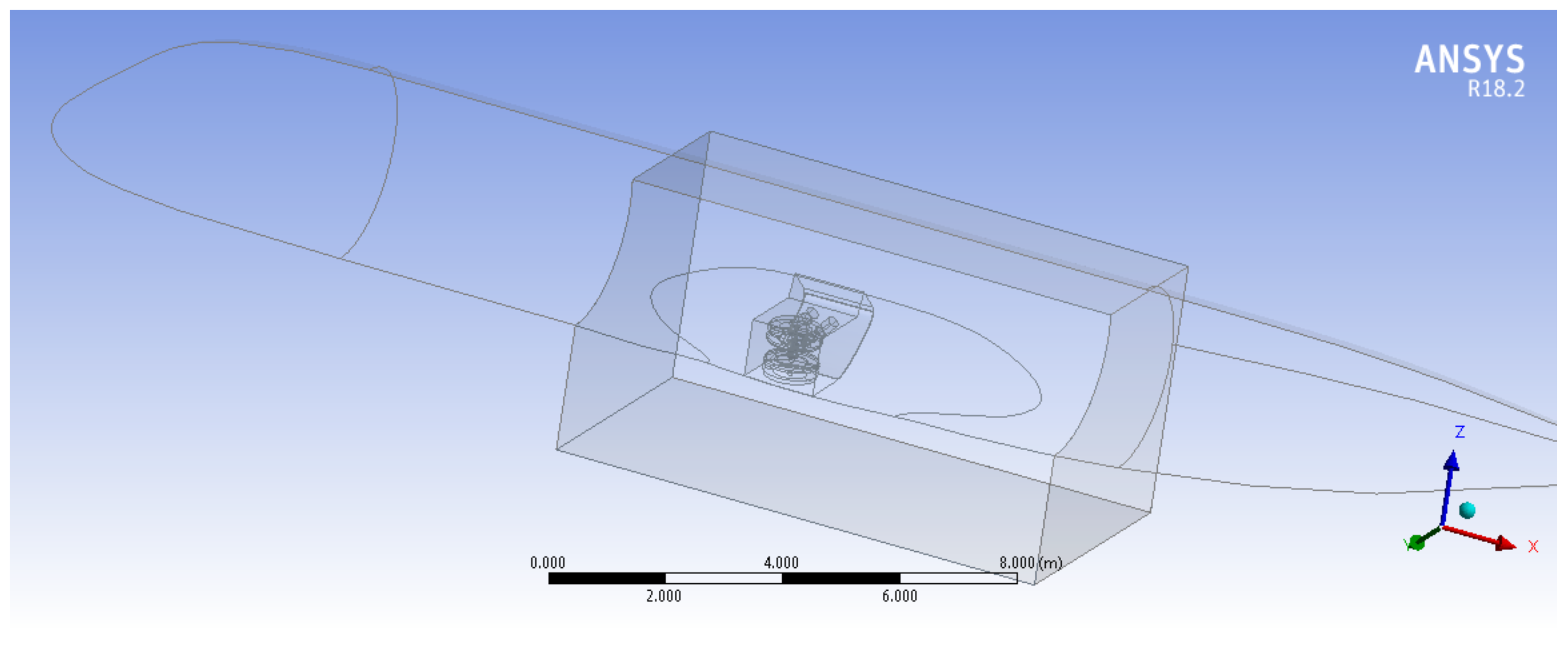
Nunzio Natale
1,
Giovanni Paolo Reina
2 and
Antonio Piccolo
3
1
Engineering Department, University of Campania Luigi Vanvitelli, Via Roma 29, 81031 Aversa, Italy
2
Altran Italy, Strada del Drosso 33, 10135 Torino, Italy
3
Leonardo Aircraft Company, 80038 Pomigliano d’Arco, Italy
*
Author to whom correspondence should be addressed.
Aerospace 2020, 7(6), 68; https://doi.org/10.3390/aerospace7060068
Submission received: 21 April 2020 / Revised: 15 May 2020 / Accepted: 26 May 2020 / Published: 29 May 2020

Abstract

:
Computational fluid dynamics is employed to evaluate the mean aerodynamic loading on the retractable landing-gears of a regional transport commercial aircraft. The mean turbulent flow around simplified landing-gear systems including doors is simulated by using the Reynolds-averaged Navier–Stokes approach, where the governing equations are solved with a finite volume-based numerical method. Using a dynamic meshing method, the computational grid is automatically and continuously adapted to the time-changing geometry, while following the extension/retraction of the landing-gear systems. The temporal evolution of the aerodynamic forces on both the nose and the main landing-gears, along with the hinge moments of the doors, is numerically predicted. The proposed computational modeling approach is verified to have good practical potential when compared with reference experimental data provided by the Leonardo Aircraft structural loads group.

1. Introduction

Retractable landing-gears are highly critical subsystems of commercial aircraft. They must be accurately designed to have minimum weight and volume, together with high performance and a long life, while meeting all the prescribed regulatory and safety requirements. Along with experimental studies, landing-gear design and development can be drastically improved by means of preliminary computer simulations, which reduce the cost of further studies and the risk of late design fixes. Among the different methodologies that are employed for this purpose, Computational Fluid Dynamics (CFD) analysis has been becoming more and more important. In fact, CFD has been strongly emerging as an effective tool for industrial aerodynamics research [1,2], where CFD simulations are being used to understand the flow physics around rudimentary landing-gears, e.g., [3,4].
The numerical simulation of the turbulent flow around retractable landing-gears, due to the presence of a number of moving bluff bodies with different sizes and shapes, is very challenging [5,6]. The turbulent wakes behind the different parts need to be simulated, along with the interaction of the wakes generated by upstream components impinging on downstream ones. The complex airflow can lead to large fluctuations in the aerodynamic forces acting, for instance, on the landing-gear doors, and the resulting unsteady loads can cause serious issues when lowering/retracting the landing-gear systems. CFD techniques can be used to simulate the flow field around these complex systems in order to determine the time history of the unsteady forces, while the predicted mean loads can be used as input for the aircraft structures’ design. For instance, CFD calculations can provide the preliminary estimation of the hinge moments of the landing-gear doors, which helps to size the hydraulic actuators for the release/retraction of the system. In the framework of industrial aerodynamics, the studies that are typically conducted make use of the Finite Volume (FV) discretization approach, supplied with Reynolds-averaged Navier–Stokes (RANS) turbulence modeling procedures, e.g., [7,8]. Typically, an eddy viscosity-based diffusion term is introduced into the momentum equations to mimic the effects of turbulence, while solving additional evolution equations for the turbulence variables. In this study, dealing with complex geometries and unsteady flow configurations, the more sophisticated unsteady RANS method is utilized [9,10,11].
The main goal of the present work is the computational evaluation of the mean aerodynamic loads on a retractable tricycle-type landing-gear that is commonly used for regional transport commercial aircraft. The analysis focuses on the validation of the proposed computational modeling approach with the distinctive feature of using a real-case landing-gear geometry, as provided by the Leonardo Aircraft researchers, rather than rudimentary models, as is typically done. The simulation of the turbulent flow field around simplified models of both the nose and main landing-gear systems is carried out using a dynamically adaptive unstructured grid that is automatically modified in time, while following the extension/retraction of the landing-gear systems. The numerical simulations are conducted using the solver ANSYS Fluent, which is commonly and successfully employed for building virtual wind tunnels in industrial aerodynamics research [12,13,14,15,16]. The present results are validated by comparison with reference experimental data that are provided by the industrial aerodynamicists.
The remainder of this manuscript is organized as follows. In Section 2, the overall computational modeling approach is introduced. The results of the numerical simulations that are performed for different flight conditions are presented and discussed in Section 3, while the validation against empirical industrial data is conducted in Section 4. Finally, some concluding remarks are given in Section 5.

2. Computational Modeling

In this section, the overall computational modeling and simulation approach is introduced. After presenting the proposed methodology, the geometric models of the landing-gear systems under examination are made known. The numerical meshing technique and the turbulence modeling approach that are used are briefly described.

2.1. Methodology

The design and development of retractable landing-gear systems require the knowledge of the aerodynamic loads associated with the time-dependent positions of their various components. However, given the motion laws of the different parts, the overall geometric configuration can be related to a single angular position, say θ , representing, for instance, the rotation angle of the landing-gear strut. Since the present research focuses on the validation of the proposed computational modeling approach, having the advantage of using a real-case landing-gear geometry rather than a rudimentary model, the speed of deployment/retraction is considered given and known. The motion of realistic landing-gear systems of a small commercial aircraft is faithfully reproduced in the numerical simulations by utilizing the time and position data provided by the industrial research partner. Depending on the simulated flight conditions, the aerodynamic loading is determined for different relative wind directions, that is for different angles of attack, say α , and sideslip, say β . The definition of these angles is illustrated in Figure 1, where the side and plan views of the aircraft under study are depicted, with V representing the relative wind velocity.
By assuming α and β as independent variables with a reduced range of variation, whereas θ = θ ( t ) , the following linear approximation, for a general loading coefficient C N , is considered:
C N ( α , β , θ ( t ) ) C N 0 ( t ) + C N α ( t ) α + C N β ( t ) β ,
where C N 0 ( t ) = C N ( 0 , 0 , θ ( t ) ) . The partial derivatives C N α ( t ) and C N β ( t ) have to be evaluated for suitable values of angles of attack and sideslip. This way, the unsteady aerodynamic loading is completely characterized by the three time-dependent parameters C N 0 , C N α , and C N β . To determine these coefficients numerically by using a virtual wind tunnel, one possibility would consist of performing a number of different calculations with different values of ( α ; β ) , for some prescribed instantaneous configurations of the landing-gear system, say for θ i = θ ( t i ) ( i = 1 , , n ). In the simplest scenario, for each chosen position, once a computation with zero angles of attack and sideslip has been conducted to estimate C N 0 , two additional calculations would suffice to approximate C N α and C N β as fractional incremental ratios.
In this work, alternatively, numerical flow simulations with moving boundaries are conducted for given couples ( α ; β ) , where the body-fitted numerical grids are continuously modified during the calculation, following the motion of the different components of the landing-gear systems. The present dynamic approach allows the numerical solution to follow more closely the unsteady flow evolution and, thus, to represent better the time history of the stresses acting on the various bodies surfaces and, in particular, on the landing-gear doors. Moreover, even considering the time needed for the mesh generation and the pre-processing phase, a substantial savings of computational time is achieved by using the dynamic meshing technique with respect to the equivalent number of static computations.

2.2. Geometric Models

The present study focuses on the computational evaluation of the aerodynamic loading on a retractable tricycle-type landing-gear of a small commercial aircraft. The geometry of both simplified systems under investigation, namely the nose landing-gear (NLG) and the main landing-gear (MLG), is introduced in the following. Starting from the complex geometries that are provided by the Leonardo Aircraft structural loads group, the present geometric models are simplified to make the computational cost of the numerical simulations affordable. However, in order to achieve a meaningful comparison with reference experimental data, the main features of the original models are maintained, differently from similar studies where rudimentary landing-gears were investigated [17,18]. The aerodynamic flow is described in a Cartesian coordinate system ( x , y , z ), where the three directions correspond to the roll, pitch, and yaw axes of the aircraft, respectively.

2.2.1. NLG Geometry

The three-dimensional geometric model for the NLG calculations is based on the generic nose structure of a short-range narrow fuselage aircraft with an NLG compartment. The landing-gear is assumed to retract fully forward and upward into the fuselage during flight. In this case, the computational domain corresponds to a square prism whose height (45 m long) is aligned with the fuselage symmetry axis, while the side length of the transverse square section is 30 m long. The fuselage model, which is cut at about a quarter of its total length, has a diameter of 3.45 m. The reduced model for the NLG system is comprised of a bay with a couple of opening/closing large front doors, a couple of opening small rear doors, a landing-gear strut, rotatable between stowed and deployed positions, and two wheels. The different parts of the system are shown in Figure 2, for both stowed and deployed positions. The rotation axes of each door and gear strut are precisely defined, along with the corresponding laws of rotation. In particular, the axis of rotation of the gear strut is parallel to the y-axis, those of the rear doors are parallel to the x-axis, whereas the front doors rotate around axes with the prescribed direction in the ( x , y ) plane. The different rotation laws are consistently assigned such that the synchronous movements of the different parts are correctly reproduced. During the deployment of the gear, which lasts for 10 s, the front doors are opened and then closed, while the rear doors are opened and stay open, with a final value of the opening angle that is 90 .

2.2.2. MLG Geometry

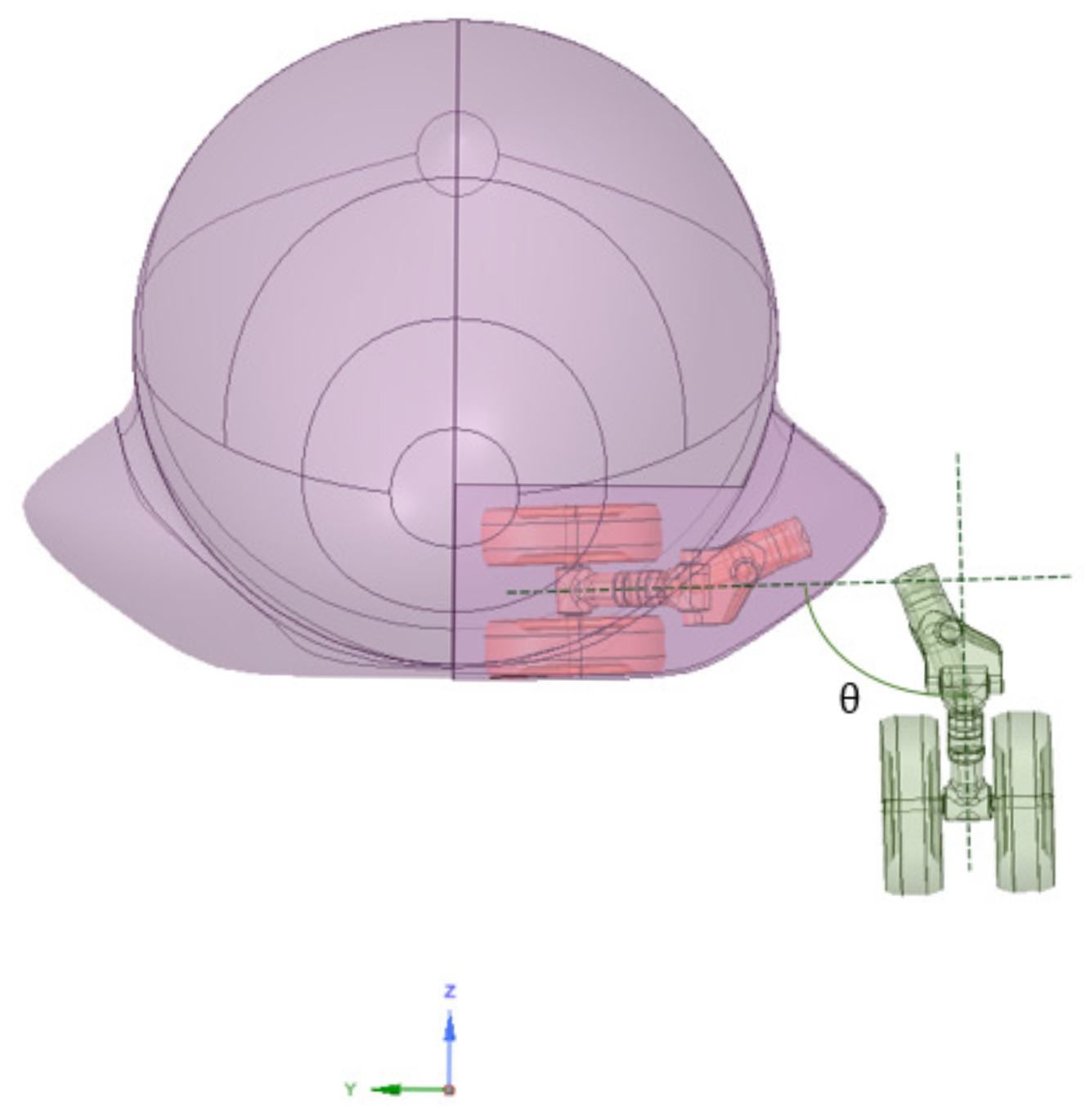
The three-dimensional geometric model for the MLG calculations is based on the same fuselage structure used for the NLG, where the entire fuselage body is taken into account. The MLG system consists of two specular components that fully retract inboard into the aircraft fuselage, while rotating around axes that are parallel to the x-axis. The reduced model for each of the two identical parts is comprised of a bay with an opening/closing door, a gear strut rotatable between stowed and deployed positions, and two wheels. Differently from the NLG, which is equipped with additional bay doors, the MLG wheels are not covered and remain exposed even when fully retracted, as is typical of short-range, regional airliners with short landing-gears and, thus, limited space between the fuselage and the ground. In Figure 3, one of the two identical MLG components is shown, in stowed position. The complete deployment of the MLG system lasts for 10 s, consistent with the NLG lowering time. The exact correspondence between the instantaneous NLG and MLG configurations is given and known, based on available time and position data. The instantaneous position of the MLG system is represented by the rotation angle of the gear strut θ , as illustrated in Figure 4. Note that, while the final position of the landing-gear strut corresponds to θ = 90 , the opening angle for the MLG doors achieves a maximum opening angle of 124 , when the system is fully deployed. For the MLG simulation, the computational domain is represented by a square prism whose height (130 m long) is aligned with the fuselage symmetry axis, while the side length of the cross-section is 60 m long. It is worth noting that, for the calculations with zero sideslip angle, half of the above computational domain is actually employed, while imposing a symmetry condition at the plane y = 0 . For the simulations with non-zero sideslip angle, the mesh mirroring procedure is exploited to build the whole FV grid.

2.3. Dynamic Meshing

The use of the dynamic meshing approach allows obtaining accurate time-dependent results because the computational grid varies in time consistently with the changing positions of the different moving parts [19,20]. In order to avoid the deterioration of the mesh quality and/or the degeneration of existing FV cells, due to the geometry modification, two different methods are used, which are referred to as smoothing and remeshing. The former technique consists of moving the interior nodes of the mesh, without changing their number and connectivity, where appropriate. The latter technique allows for the local update of the mesh by either adding or deleting cells, where the boundary displacement would be otherwise too large with respect to the local mesh size. Following previous studies for bluff body flows [14], the remeshing and the diffusion-based smoothing techniques are simultaneously used in the present research. The computational cost of such a dynamic approach is high due to the requirement of fine grids and small time steps, in order to ensure both the desired numerical accuracy and the stability of the calculation. However, the application of the dynamic meshing procedure is not needed in the whole computational domain, but only in flow regions that are expected to be actually influenced by the deployment/retraction of the landing-gear systems, while opening/closing the doors and moving the different system components. Therefore, computational sub-domains where the dynamic meshing is effective are properly defined, with the FV grids in the rest of the computational domains staying unaltered. Practically, these space regions must contain the bays, the doors, and the landing-gear structures, regardless of the instantaneous system configurations. For the present numerical simulations, these sub-zones are shown in Figure 5, for both landing-gear systems. Initially, two unstructured meshes are generated in the two different sub-domains, while imposing the grid conformity at the interfaces between them. For instance, the overall numerical grid for the NLG simulation with non-zero sideslip angle involves about two million computational cells, with the maximum skewness factor being equal to 0.85 , which ensures the good quality of the FV mesh. Due to the dynamic meshing approach, the latter parameter is directly controlled during the calculations.
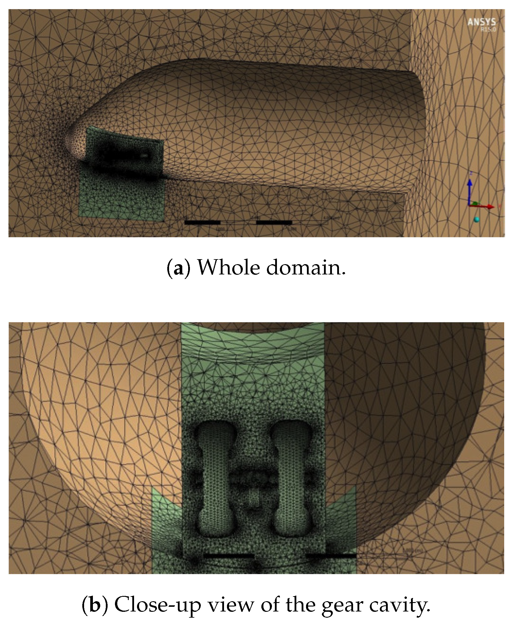
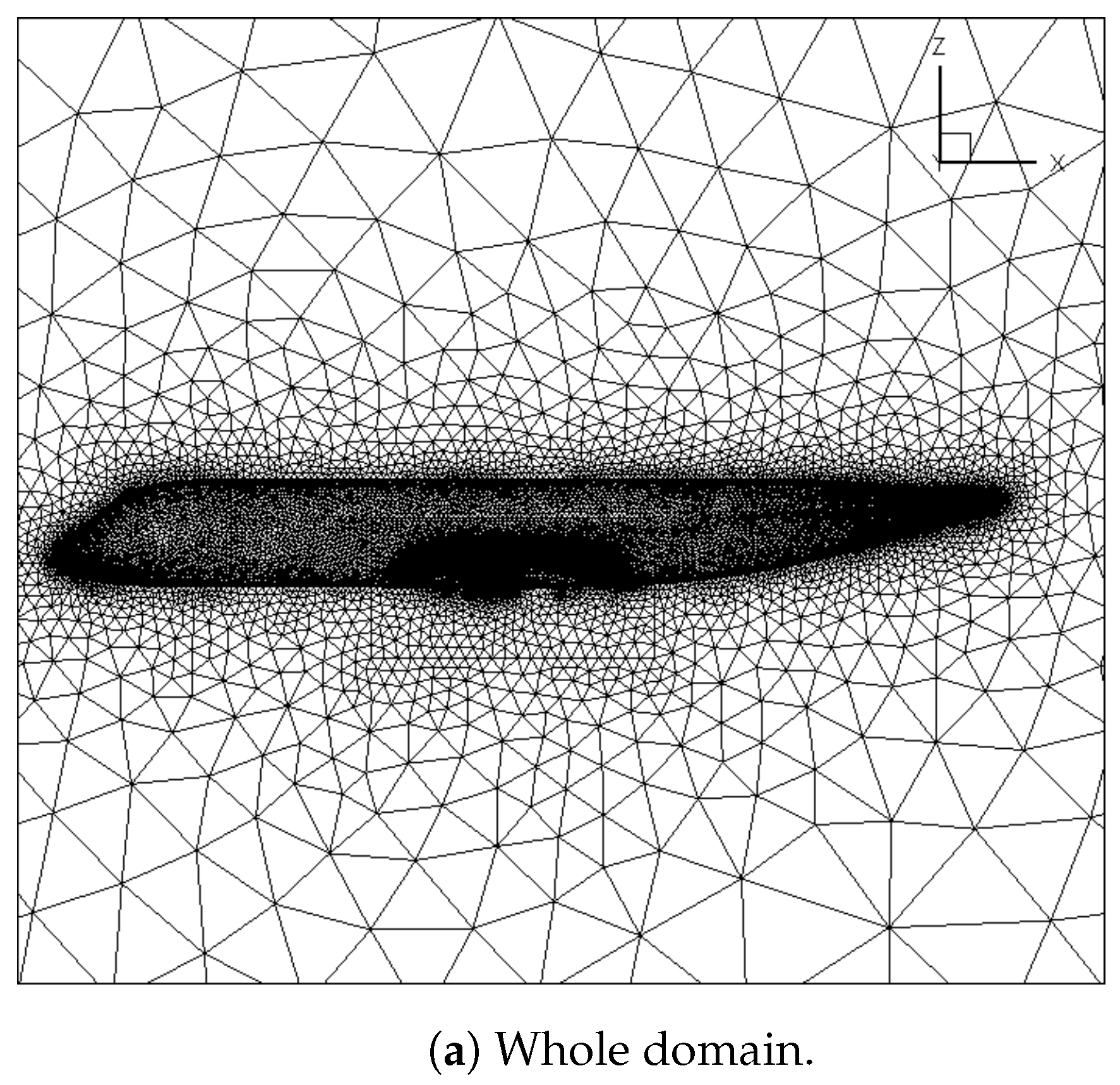
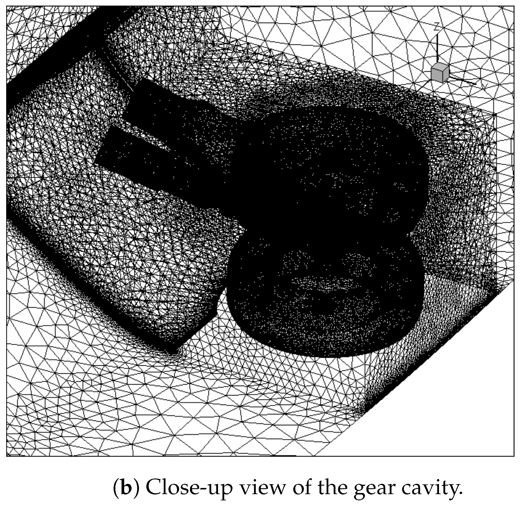
A global view of the initial grid, which corresponds to the stowed NLG system, along with a close-up view of the mesh inside the gear cavity, is shown in Figure 6. The different background color that is used allows for the easy visualization of the two different sub-domains, where the dynamic meshing is either active or not. Similar considerations can be made for the MLG model. The initial grid, which corresponds to the stowed MLG system, is illustrated in Figure 7, where a global view at the symmetry plane is reported, along with the close-up view of the landing-gear cavity. For instance, the computational grid used for the MLG simulation with non-zero sideslip angle is made up of about five million FV cells, with a maximum skewness of 0.81 , as is controlled.

2.4. Turbulence Modeling

The aerodynamics of the landing-gears is predicted by solving the RANS governing equations, which describe the mean turbulent flow field around the aircraft. In this work, the one-equation Spalart–Allmaras (SA) model [7] is used, where the closure is achieved by solving an additional evolution equation for a modified eddy viscosity variable. Due to the complex geometry flow under investigation, the turbulent boundary layer is modeled using a wall-function approach, where semi-empirical correlations are employed instead of resolving the near-wall region. This way, the wall boundary conditions are implemented so that relatively coarser meshes can be used in the FV calculations. The equations governing the RANS models, which are not reported here for brevity, can be found, for instance, in Wilcox [21]. The unsteady RANS method is commonly used for the simulation of both incompressible and compressible aerodynamic flows, e.g., [8,11]. Here, the governing equations are solved in the computational domains described above, imposing velocity inlet and pressure outlet boundary conditions.

3. Results and Discussion

A number of different calculations were conducted with freestream velocity directions that mimic realistic flight conditions at Mach number 0.27 . In the following, the results corresponding to three baseline configurations of particular interest are shown and discussed, for both landing-gear systems. Together with the configuration with zero angles of attack and sideslip (I), two other configurations were considered, with either α = 4 (II) or β = 5.7 (III), to examine the effect of increasing these angles. The six different calculations that are presented in this work are summarized in Table 1, along with the corresponding number of FV cells. The mesh resolution that was used represented a fair compromise between numerical accuracy and computing time, as empirically found through a grid independency study. As the present computational model employed a dynamic meshing procedure, a preliminary analysis was conducted for a limited number of frozen geometries, corresponding to different positions of the landing-gear systems, by using three different static grids with different resolution. The FV mesh was naturally refined in the landing-gear zones, with the overall number of computational cells resulting in being the same order as for similar studies [22,23]. The mean aerodynamic loads are reported only for the deployment phase. In fact, as practically demonstrated by the simulation of the retraction phase, the loading evolution for a complete cycle (opening/closing) showed a substantially specular behavior.

3.1. NLG Simulation

For the NLG configuration, the flow Reynolds number based on the wheels diameter was Re = 3.6 × 10 6 . The sufficiently small integration time step of 5 × 10 4 s was prescribed in order to maintain a Courant–Friedrichs–Lewy (CFL) number of unitary order and, thus, to achieve an accurate and time consistent numerical solution. As for the computational time, for example, the flow simulation for the NLG–I case took about three days on a parallel workstation that employed 12 Intel Xeon Gold 2.2 GHz processors. For each flow configuration, in order to obtain meaningful initial conditions, a steady solution for the initial geometry, corresponding to the stowed position of the landing-gear with all the doors closed, was first performed. Starting from this preliminary solution, due to the dynamic meshing approach, the FV grid that was actually employed automatically varied in time, while following the system deployment. This is apparent from inspection of Figure 8, where the instantaneous meshes at four subsequent time instants during the lowering phase, which were t = 3 , 6, 8 and 10 s, are drawn in the clockwise order. The views reported in the figure corresponded to the symmetry plane of the computational domain. Apparently, the continuous rotations of the doors and the landing-gear rod affected the spatial distribution of grid points. The mesh quality was actually maintained during the simulation as demonstrated by the maximum value of the skewness that was controlled. In fact, the use of the diffusion-based smoothing technique allowed for the optimal grid evolution, which avoided excessive mesh thickening.
To illustrate the numerical solution, the instantaneous distributions of the pressure and the skin friction coefficients on the different moving parts of the NLG system are reported in Figure 9 and Figure 10, respectively. Here, the gauge pressure and the wall shear stresses were non-dimensionalized by the dynamic pressure of the air stream, namely q ref = 1 2 ρ V 2 , with ρ being the freestream air density. The contours corresponding to the four doors, the gear leg, and the wheels are depicted at the same time instants considered in Figure 8.
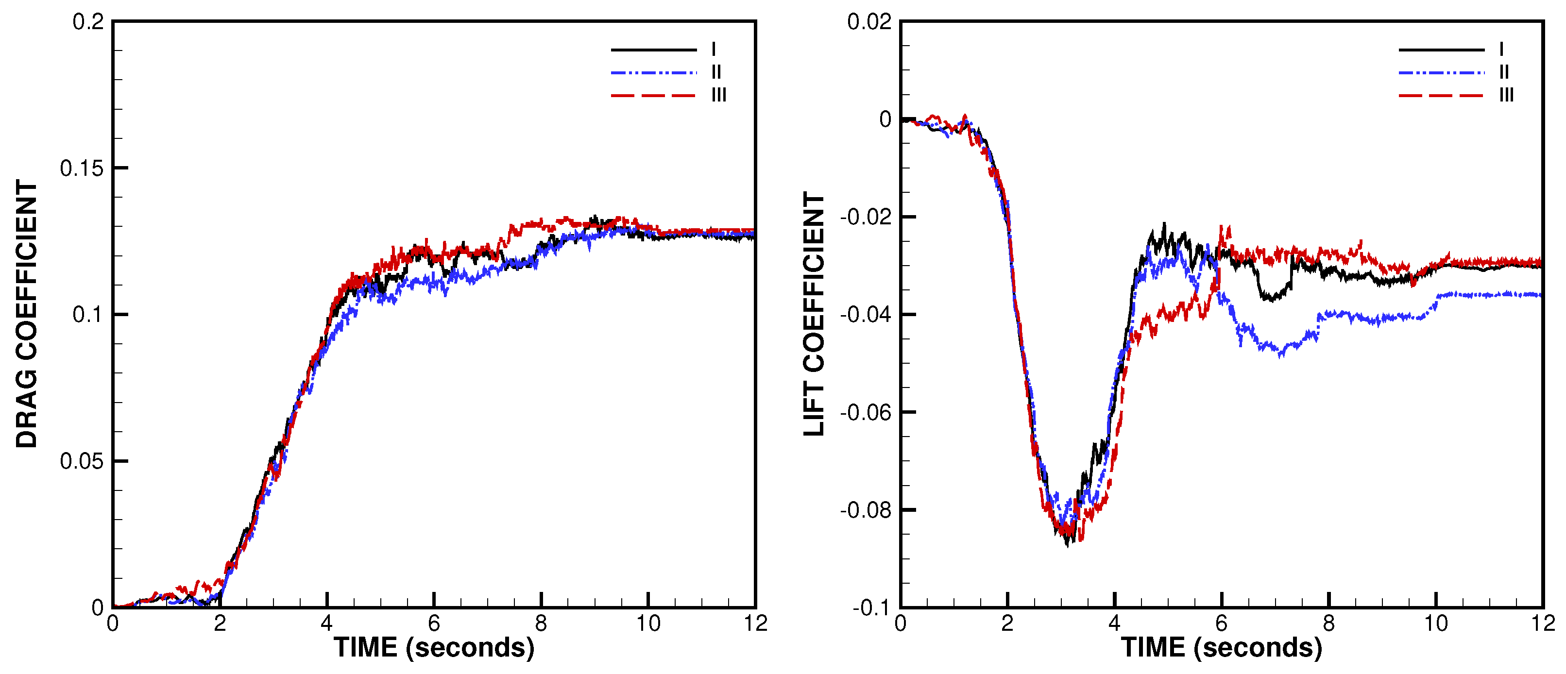
As the system deployed, the stress distributions variation led to the existence of time-dependent aerodynamic loading on the different moving parts. The time histories of the mean loads on the landing-gear strut and wheels are reported in Figure 11, in terms of force coefficients, for the three different simulations NLG–I, II, and III. The drag and lift coefficients are defined as C D = D / ( q ref A ref ) and C L = L / ( q ref A ref ) , where D and L are the components of the mean aerodynamic force acting along and perpendicular to the relative wind direction, respectively, while A ref stands for the unitary surface area. Apparently, the aerodynamic force appeared as soon as the gear strut left the cavity at t 2 s, and rose with the gear leg rotation and the doors opening. While the drag component monotonically increased, achieving its maximum value when the gear strut and wheels were completely immersed in the oncoming flow, the lift force showed a more complex behavior. After the initial rise, the intensity of the negative lift diminished. This was mostly due to the changing position of the large front doors that were resealed, while directly affecting the exposure of the system to the main air stream. Furthermore, the lift component approached a final value that depended on the angle of attack. As expected, once the deployment phase of NLG terminated at t = 10 s, the aerodynamic forces maintained practically steady values.
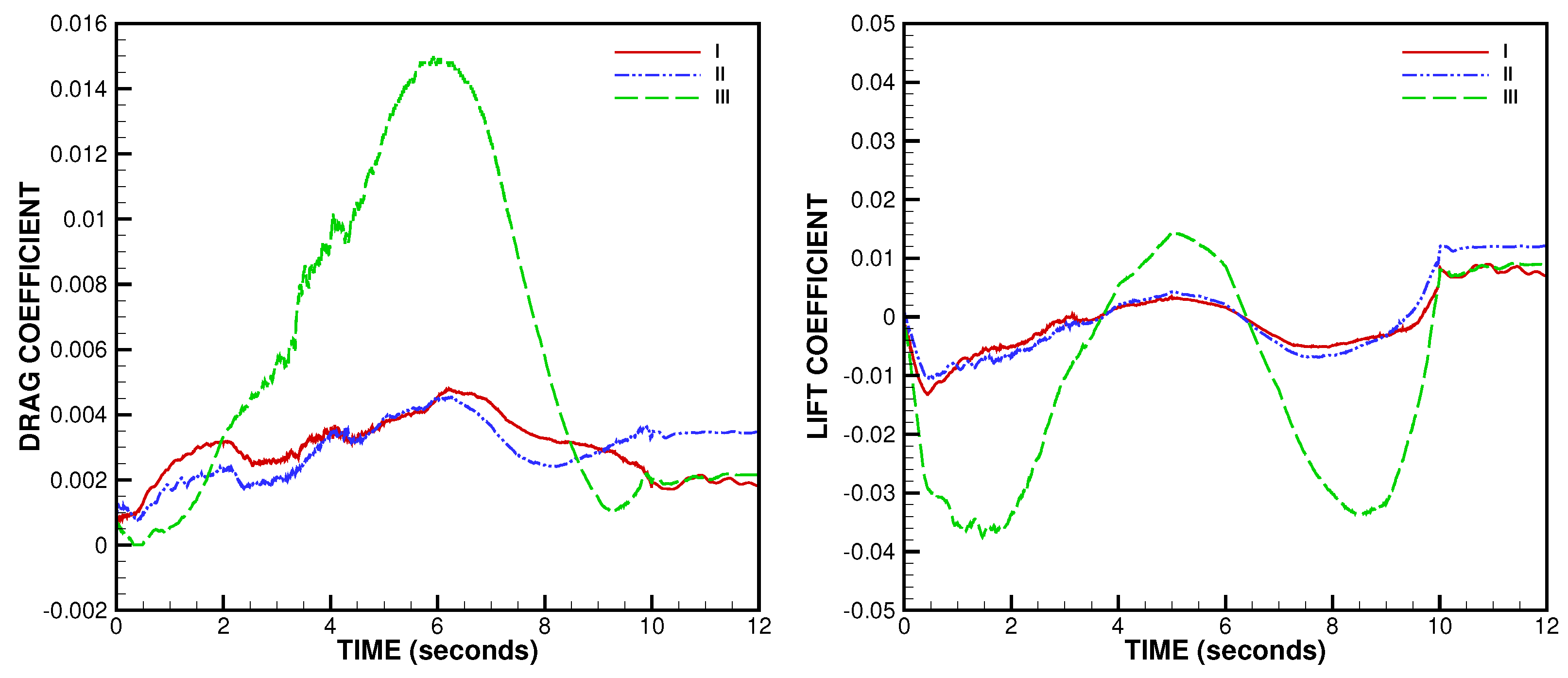
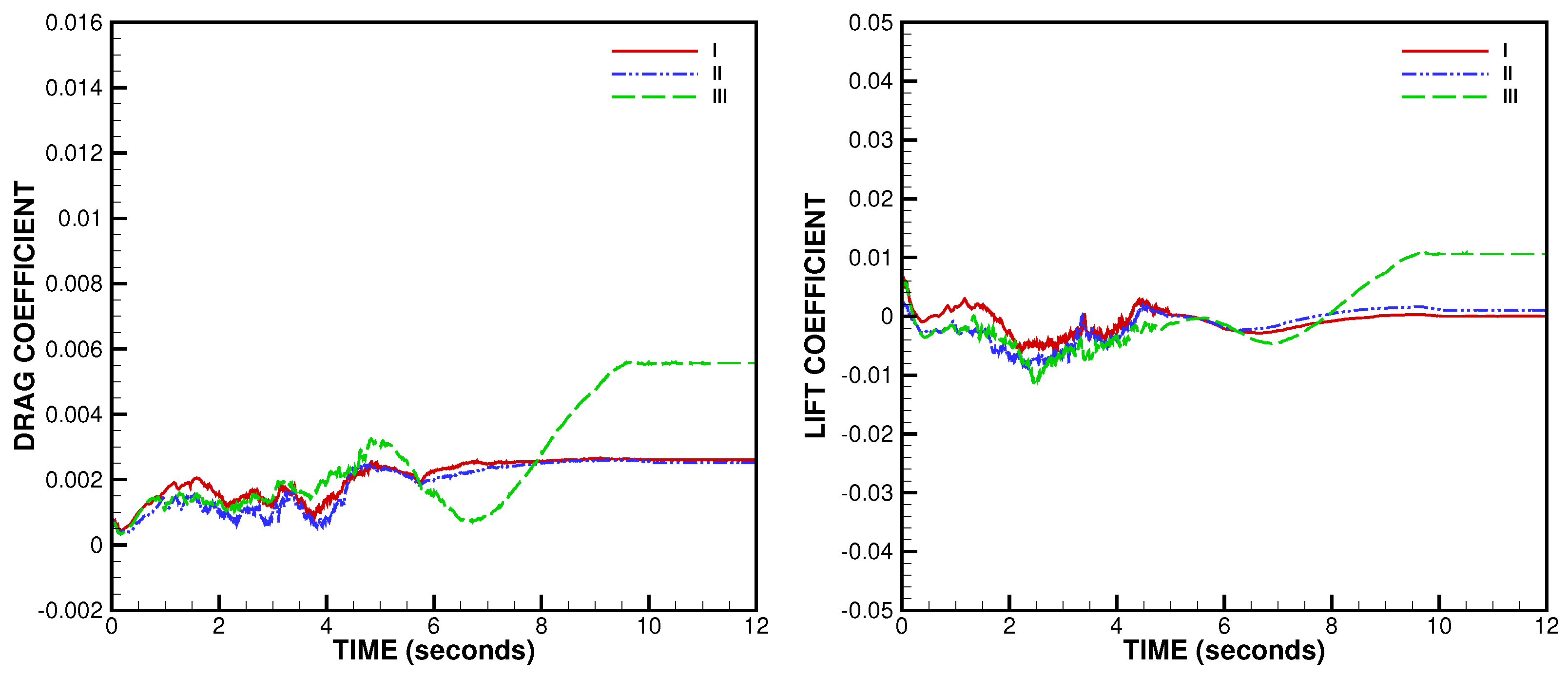
The time histories of the mean aerodynamic forces acting on large front and small rear NLG doors are reported in Figure 12 and Figure 13, respectively. The right doors (as seen by the pilot) were considered because, given the relative wind velocity vector in the case NLG-III, which had a positive component along the y-axis, higher aerodynamic loading occurred for the downwind doors with respect to the upwind ones. Here, for the sake of clarity, two different scales were adopted for the two different force coefficients. The aerodynamic loads on the doors showed a complex behavior due to the complex fluid dynamic scenario, which involved massively separated flows. For the simulations NLG-I and II, with zero sideslip angle, the drag force on the doors, which was almost aligned with the main air stream, resulted in being relatively low, due to the their small friction area and thinness, which led to the existence of reduced wakes. Looking at the solution NLG-III, the sideslip angle showed a remarkable influence, for both front and rear doors. For the downwind front door, in particular, the aerodynamic loading achieved a relatively high level when the door was completely open. As for the final forces, the difference between the front doors, which were closed, and the rear doors, which remained open, was evident.

3.2. MLG Simulation

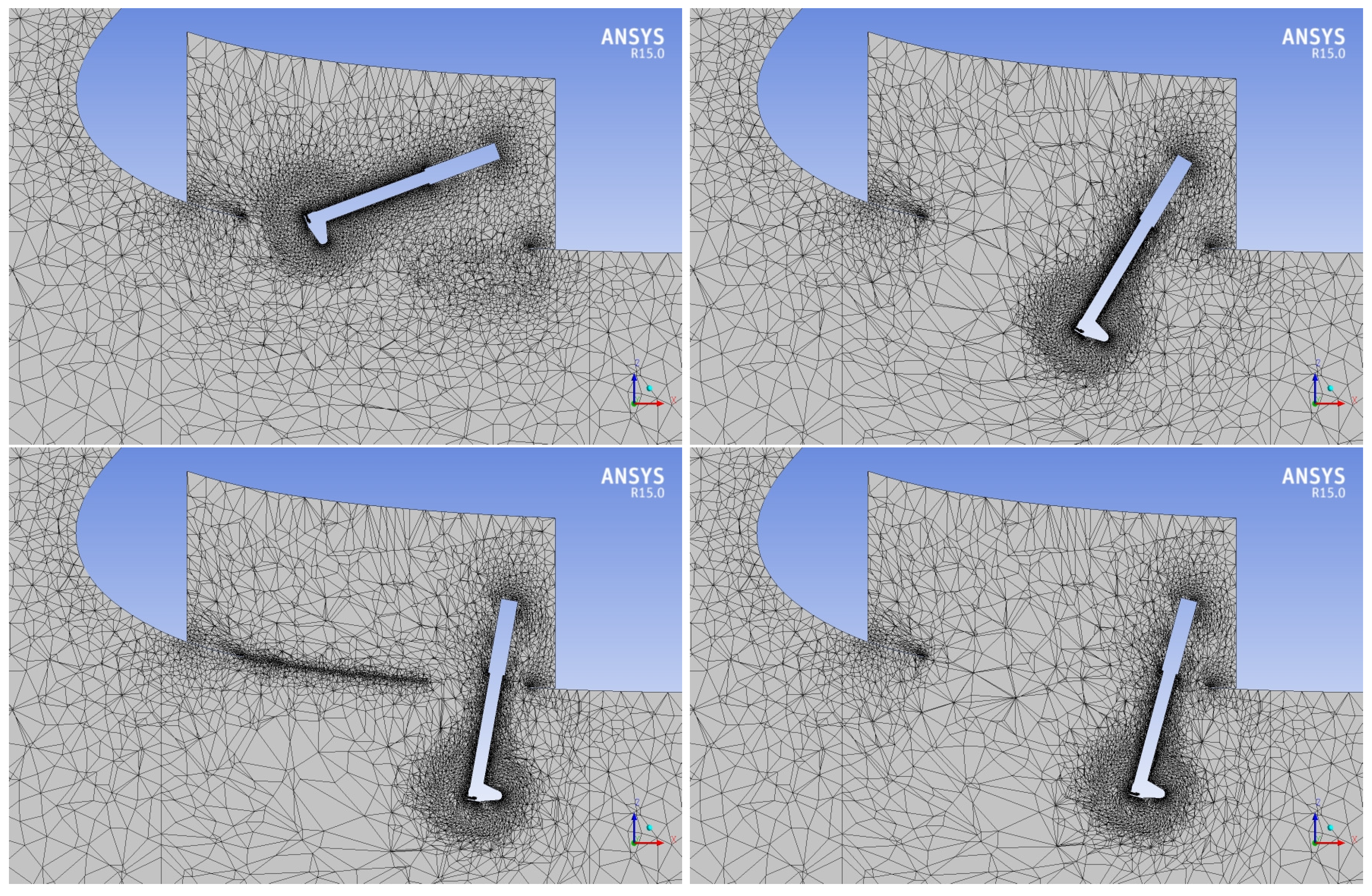
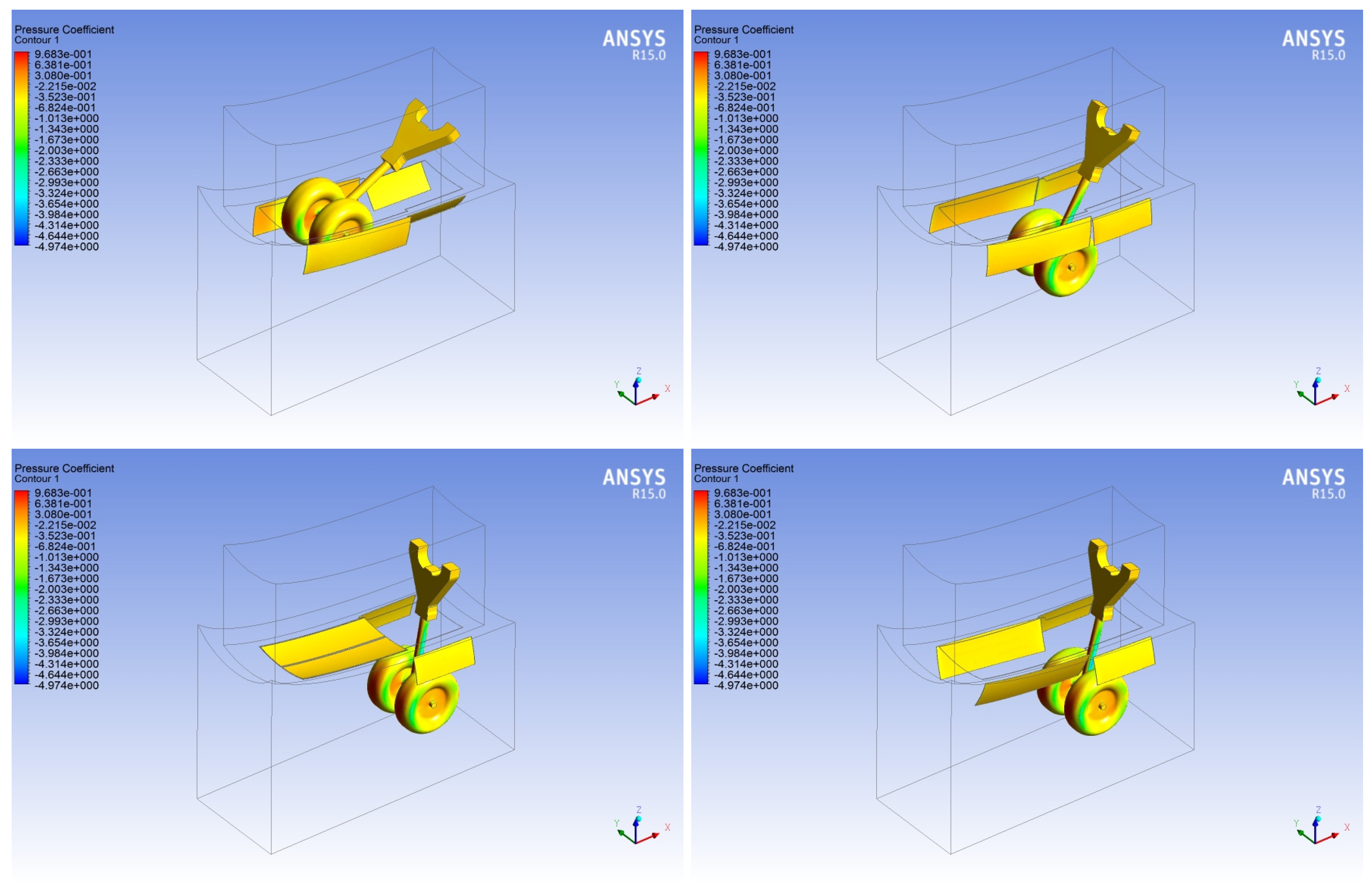
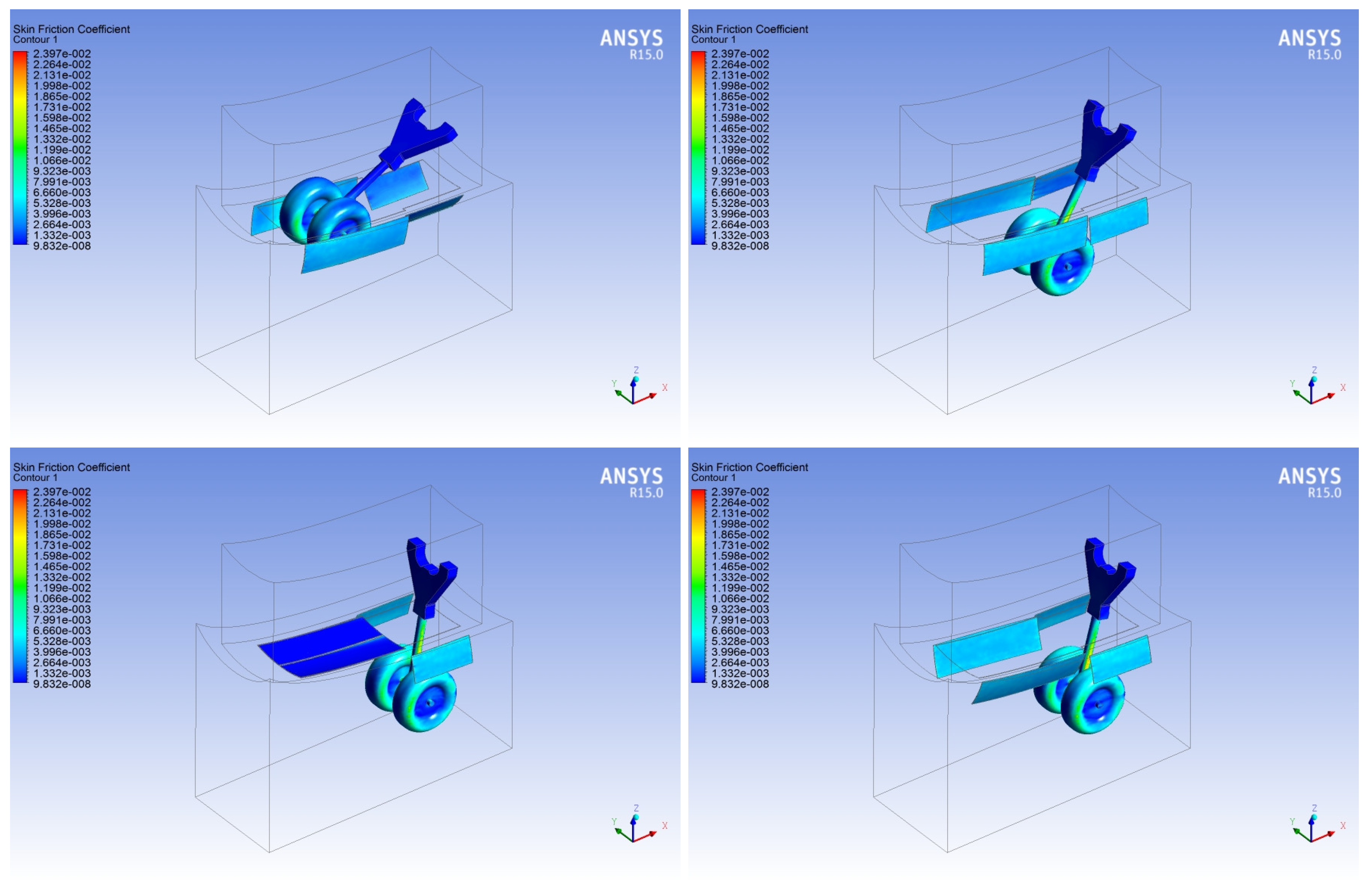
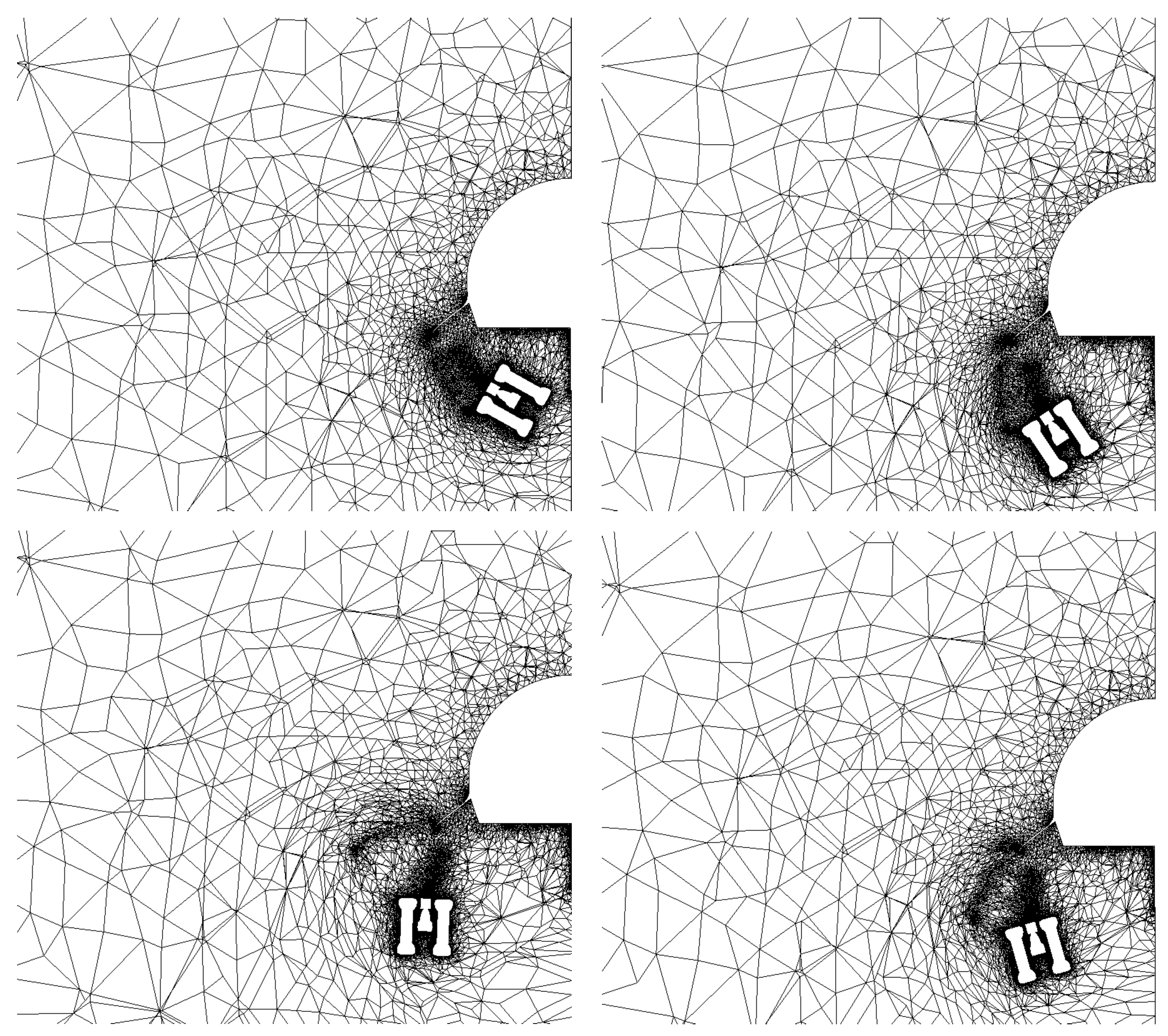
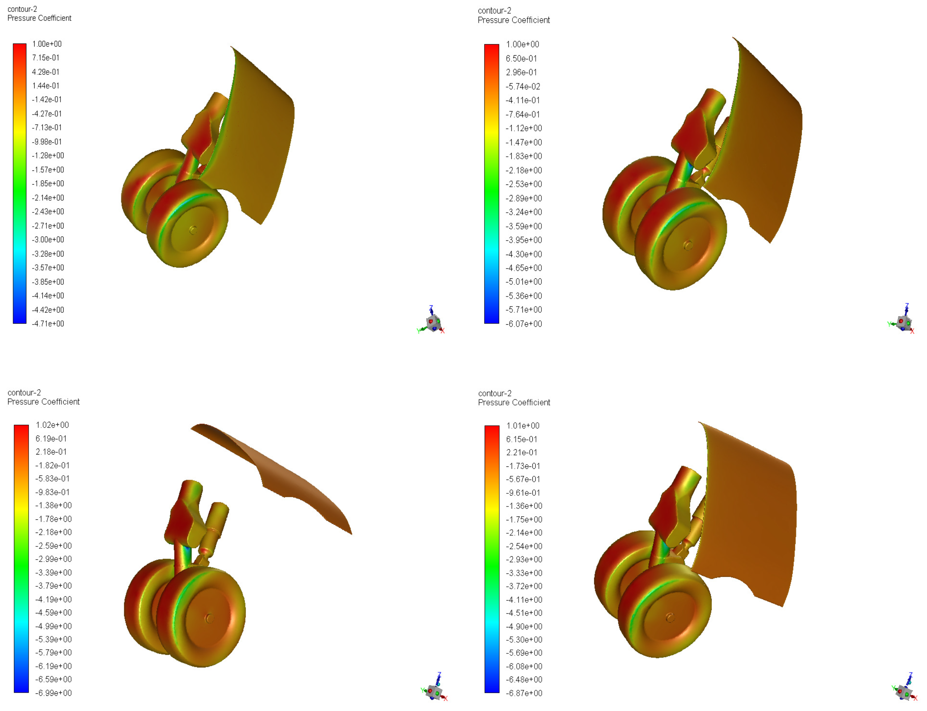
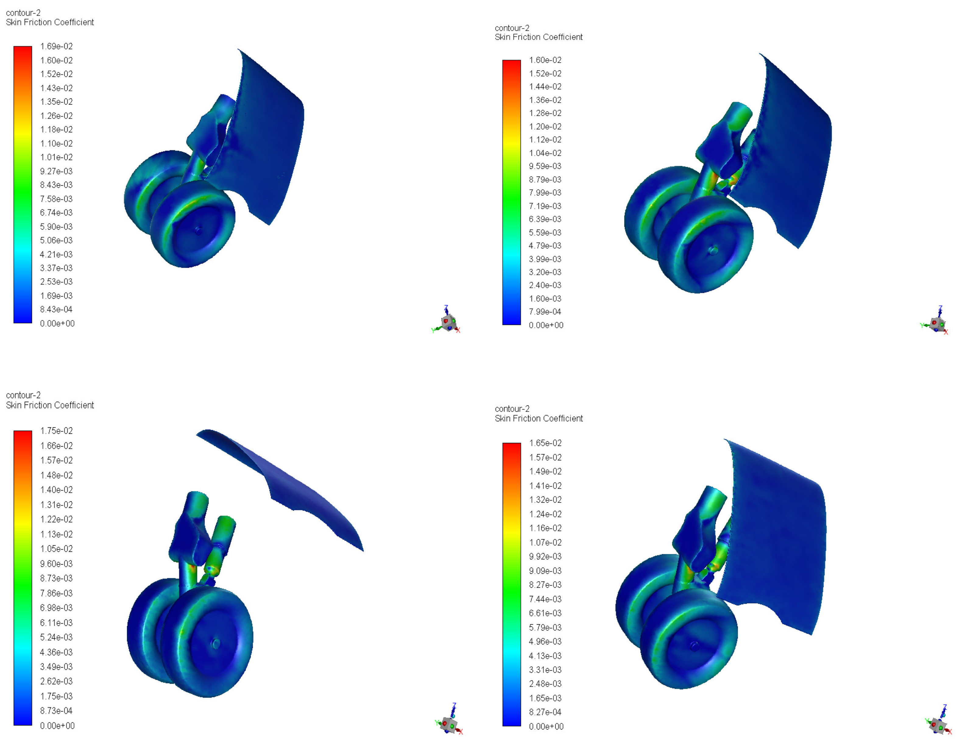
Given the distance between the two systems, the MLG aerodynamics was assumed independent of the NLG wake evolution, so that the MLG simulation could be independently conducted. However, as previously discussed, there existed a one-to-one correspondence between the instantaneous positions of the two different systems. For the MLG simulation, three baseline computations with the same different air stream velocity directions as for the NLG simulation are presented. Here, the flow Reynolds-number based on the wheels diameter was Re = 5.7 × 10 6 . The unsteady RANS equations were solved with an integration time step of 2.5 × 10 3 s. The whole calculation, which was conducted by employing the same parallel workstation utilized for the NLG simulation, took about eight days for the MLG–I case, for example. For each of the three configurations, a steady solution for the initial geometry, corresponding to the stowed position of the landing-gear with doors closed, was first performed. The time-dependency of the spatial mesh was apparent from inspection of Figure 14, where the instantaneous FV grids at four subsequent time instants during the deployment, which were t = 3 , 6, 8 and 10 s, are reported in clockwise order. Note that the two-dimensional views shown in this figure correspond to a cut operated in the computational domain at x = 0 . The corresponding instantaneous distributions of pressure and skin friction coefficients on the different parts of the MLG system are drawn in Figure 15 and Figure 16, respectively.
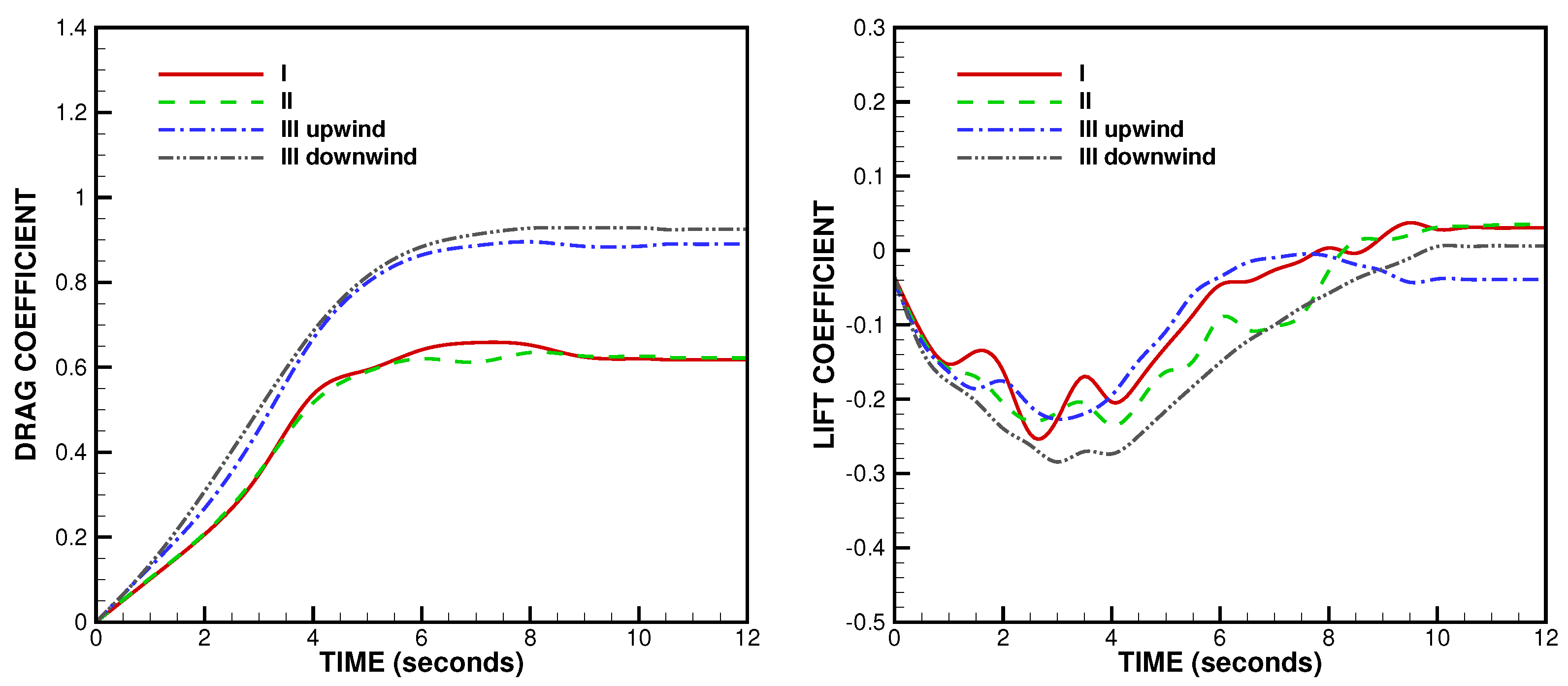
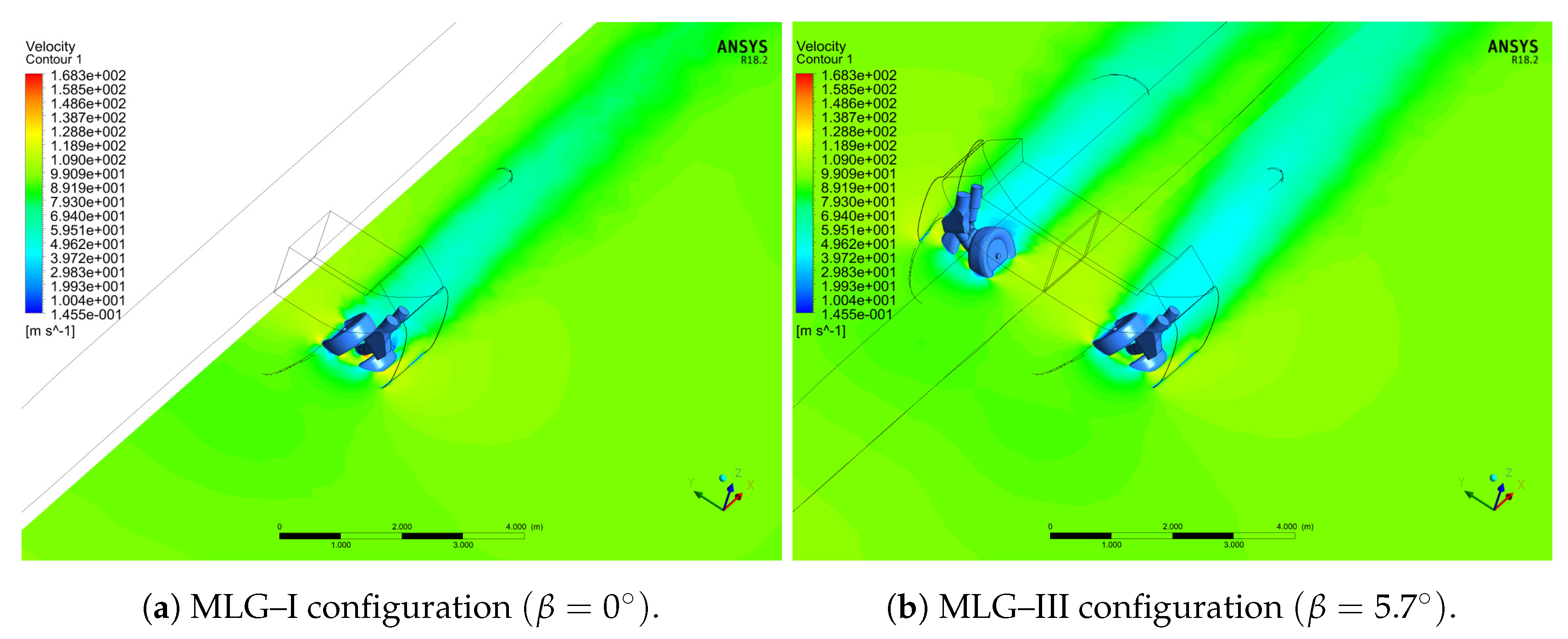
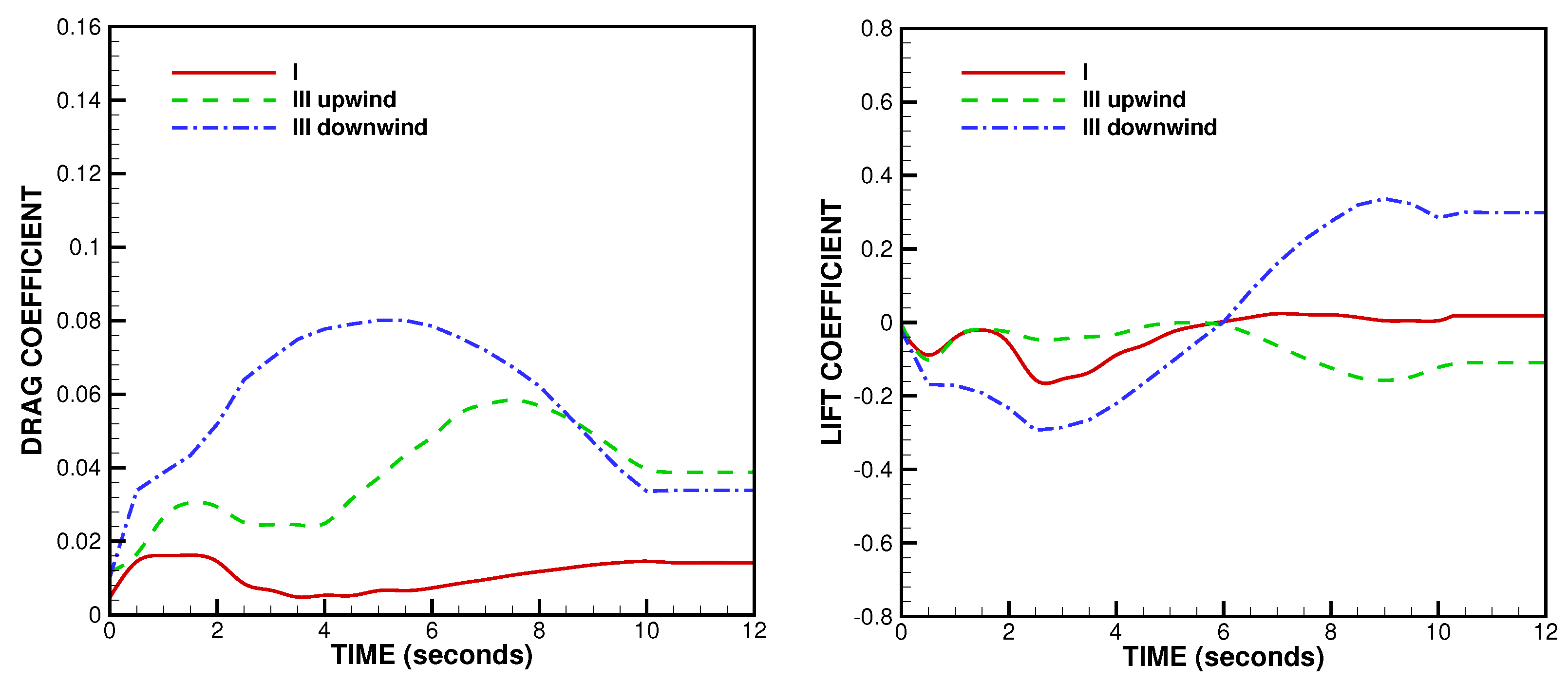
The time histories of the mean aerodynamic loads on the MLG structure, including strut and wheels, are reported in Figure 17, in terms of force coefficients per unit reference area, for the three different simulations MLG–I, II, and III. In the latter case, due to the flow asymmetry, the two different components of the MLG system were separately considered. During the lowering phase, the drag increased with the rotation of the gear leg, achieving its maximum value at t 6 s, when the system was completely immersed in the oncoming flow. The sideslip angle was demonstrated to have a great effect also in this case. The increased drag force for the MLG–III case could be attributed to the enlarged wake and related pressure drag, as illustrated in Figure 18, where the comparison between MLG–I and III calculations is presented in terms of mean velocity contours at a given time instant. As for the lift force component, its intensity first increased and then decreased, being influenced by the changing position of the large doors. As expected, once the deployment phase for MLG had terminated at t = 10 s, both forces maintained practically steady values.
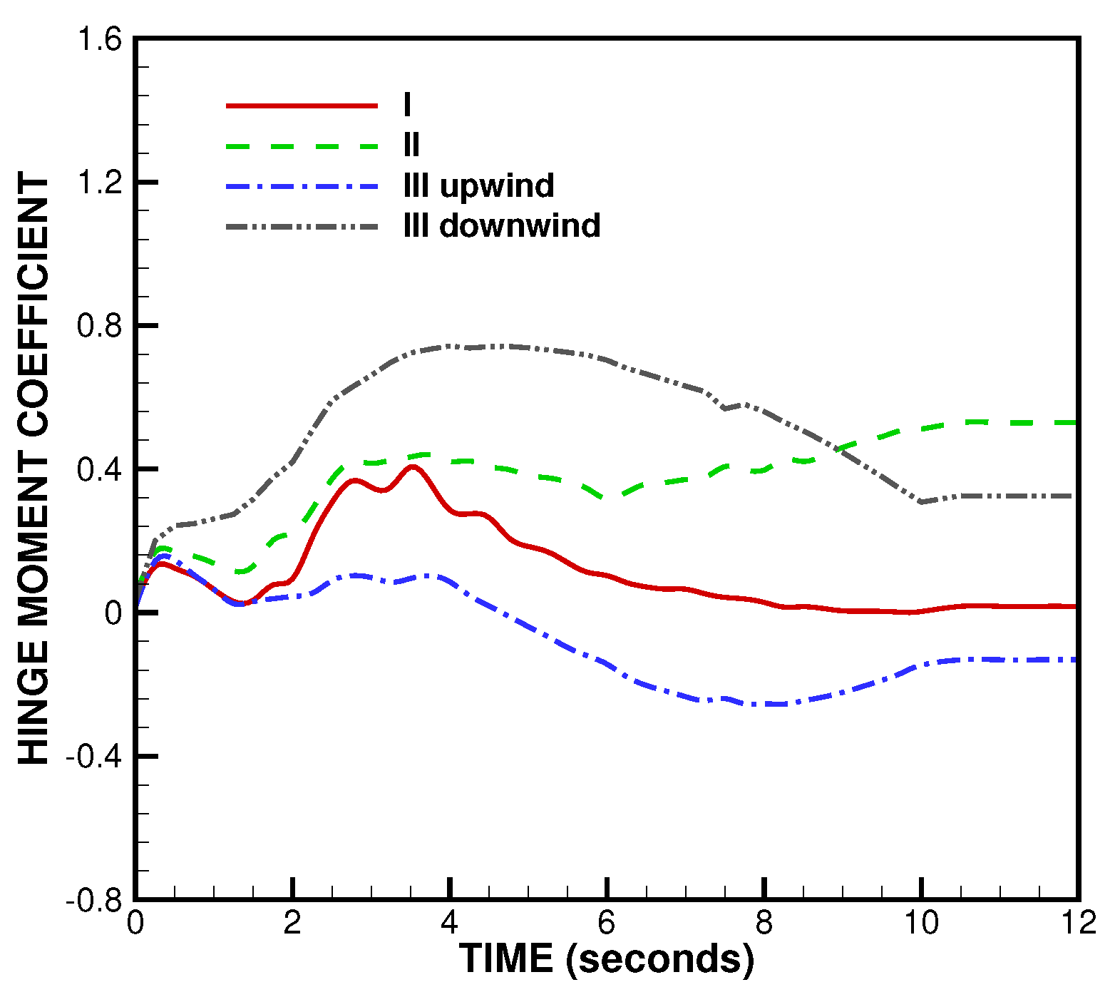
The time history of the hinge moment of the doors, which was the component of the moment of the aerodynamic force along the rotation axis, is presented in Figure 19, for the three baseline calculations. Note that the hinge moment was assumed positive in the direction of opening of the doors. It can be seen that, initially, the hinge moment was minimal. This fact was due to the presence of gaps along the doors, as well as uncovered wheels, which allowed for the balance of the pressure force acting on the outer surface and that exerted by the fluid occupying the MLG bay. As the landing-gear deployed, with the opening of the doors and the consequent circulation of fresh air inside the landing-gear bay, the pressure level on the inner surface and, thus, the hinge moment of the doors increased. Looking at the effect of the angle of attack α , the hinge moment augmented with this parameter, as was apparent by making a comparison between the results of simulations MLG–I ( α = 0 ) and II ( α = 4 ) . As for the solution MLG–III, since it corresponded to a crosswind from left to right ( β > 0 ) , the hinge moment was different for the two different MLG components. Specifically, the aerodynamic load on the downwind right door was more relevant and the hinge moment took higher values than those achieved for both cases, MLG-I and II, with zero sideslip. Therefore, the effect of increasing the sideslip angle resulted in being the most noticeable, as confirmed by looking at the drag and lift force coefficients for the doors reported in Figure 20. The important role of the sideslip angle was also emphasized in similar studies [22,23]. Due to the significant value of the lift force acting on the downwind door, apparently, the large MLG doors could be also viewed as small additional wings for the aircraft. Finally, it should be noted that no safety factors were applied in obtaining the present results. However, depending on the specific uses of the predicted aerodynamic loads, suitable safety factors could be employed.

4. Validation

In order to validate the proposed computational evaluation procedure, the present CFD results were compared to corresponding data predicted by the Leonardo Aircraft structural loads group, during the preliminary design phase of a new regional transport commercial aircraft. The reference data were obtained through empirical extrapolation by using geometrical shape scaling parameters, along with proper combinations of α and β , which were selected among various significant flight conditions of engineering interest. The different configurations were expressed in terms of different aircraft weights and center of gravity excursions, load factors, flap positions, and speeds, which were pertinent to the aircraft model under examination.
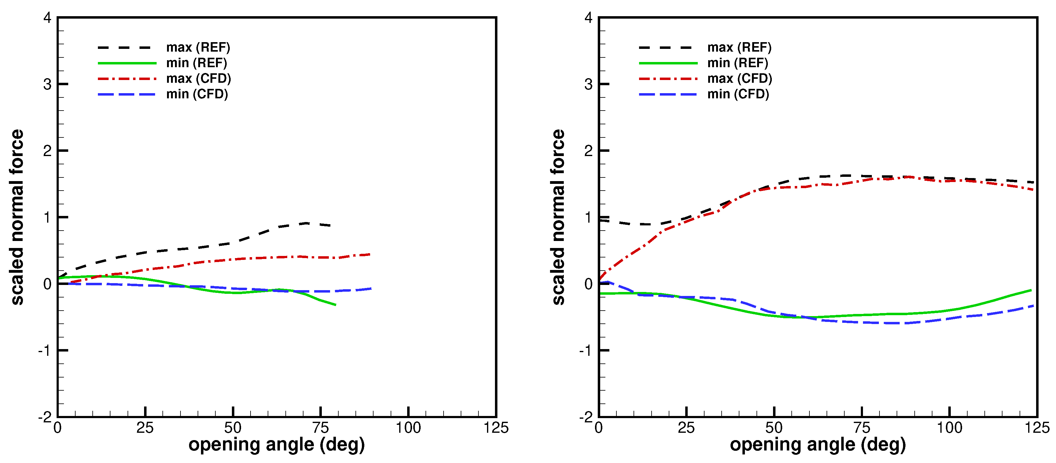
To make a meaningful comparison with reference data, the predicted normal force acting on the doors was determined from the knowledge of the corresponding numerical hinge moments, given the landing-gear geometry. The normal force coefficient was obtained by employing the simplified linear model represented by Equation (1). Namely, a number of CFD calculations corresponding to a subset of the flight parameter combinations considered by the empirical industrial method were conducted for determining the coefficients C N 0 , C N α , and C N β . These simulations used FV grid resolutions similar to those reported in Table 1. As a result, in Figure 21, the maximum and minimum values for the scaled normal forces acting on the landing-gear doors are reported, along with the envelopes of the empirical data, against the opening angle, for the two different landing-gear systems under investigation. The maximum and the minimum loadings were numerically predicted, for instance, for ( α ; β ) = ( 9 ; 15 ) and ( 0 ; 12 ) , respectively. However, the limit values were also obtained for other combinations of angles of attack and sideslip. It is worth stressing that these results are shown in non-dimensional form, without expressly indicating the reference values, because the empirical data were not classified for public diffusion.
As far as NLG was concerned, the industrial data were provided up to a rotation angle of about 80 , whereas the angle of rotation of the doors for fully deployed configuration was actually 90 . The minimum values predicted through the computational modeling approach were fully acceptable, with the absolute error resulting of order 0.1 in the chosen scale. The maximum values were clearly underestimated, where the discrepancy could achieve the value of 0.4 , for large opening angles. Considering that positive normal forces tended to pull the doors outward, maximum values corresponded to aerodynamic suction forces exerted by the air stream, due to lower pressure levels on the outer than the inner side of the doors. The present calculations seemed able to predict the correct sign, but not the intensity of the maximum pressure difference.
For MLG, the comparison between CFD and reference data appeared quite successful for both extrema, the absolute error resulting of order 0.1 , except for the maximum normal force in the range of low opening angles, say, less than 15 . In fact, the present calculations provided maximum normal force that practically vanished with the opening angle. That was consistent with analogous results found in [22], by means of both numerical simulations and wind tunnel tests, for similar commercial aircraft landing-gear geometries, with either β = 0 or 5 . On the contrary, according to reference data, significant positive values were taken by the normal force for small opening angles. This discrepancy was likely to be attributed to the fact that the present simulations did not reproduce all the different experimental configurations, on which the empirical industrial data were based. These configurations were in fact expressed in terms of a number of different flight parameters, some of which were not pertinent to the proposed computational modeling framework. Moreover, the CFD results were also affected by the approximation of the adopted geometrical models, which were simplified with respect to the real ones. That was particularly effective in the NLG case, because of the relatively lower aerodynamic loadings. Further investigation is required to examine the performance of the present CFD method to accurately predict the pressure level inside the landing-gear bays, as well as the effects of the air leakage through the existing gaps when the doors are sealed.

5. Conclusions

The present study was intended as a proof-of-concept, namely the preliminary development of a CFD-based prediction tool in the aerodynamic design of retractable landing-gears for a regional transport commercial aircraft. Different from similar studies, where the CFD predictions were obtained for generic and rudimentary landing-gear geometries, this work dealt with simplified models directly derived from real geometries provided by industrial researchers. Dynamic mesh calculations were performed for both the nose and the main landing-gear systems, with the aim of demonstrating the practical potential of the proposed methodology. The computational analysis of the aerodynamic loads on retractable landing-gears and doors was performed in different operating conditions for the opening/closing cycle. The acceptable agreement with the empirical data made available by the industrial aerodynamics researchers in terms of normal forces was achieved. There remains the possibility of developing more sophisticated computational models, which can be employed depending on the particular application and level of accuracy that is required.

Author Contributions

Data curation, N.N. and A.P.; investigation, N.N. and G.P.R.; methodology, G.D.S. and N.N.; resources, G.D.S.; supervision, G.D.S.; validation, N.N., G.P.R., and A.P.; visualization, N.N. and G.P.R.; writing, original draft preparation, G.D.S.; writing, review and editing, G.D.S. All authors read and agreed to the published version of the manuscript.

Funding

Program POR CAMPANIA FESR 2014/2020 funds managed by Italian Campania Region, promoter DAC (Campania Aerospace Technological District), project SCAVIR (Advanced Configurations Studies for an Innovative Regional Aircraft).

Acknowledgments

Authors would like to thank Leonardo Aircraft Company for providing the landing-gear data.

Conflicts of Interest

The authors declare no conflict of interest.

Abbreviations

The following abbreviations are used in this manuscript:
CFDComputational Fluid Dynamics
FVFinite Volume
RANSReynolds-Averaged Navier–Stokes
NLGNose Landing Gear
MLGMain Landing Gear
CFLCourant–Friedrichs–Lewy number

References

  1. Johnson, F.T.; Tinoco, E.N.; Yu, N.J. Thirty years of development and application of CFD at Boeing Commercial Airplanes. Comput. Fluids 2005, 34, 1115–1151. [Google Scholar] [CrossRef] [Green Version]
  2. Spalart, P.R.; Venkatakrishnan, V. On the role and challenges of CFD in the aerospace industry. Aeronaut. J. 2016, 120, 209–232. [Google Scholar] [CrossRef] [Green Version]
  3. Imamura, T.; Hirai, T.; Amemiya, K.; Yokokawa, Y.; Enomoto, S.; Yamamoto, K. Aerodynamic and aeroacoustic simulations of a two-wheel landing-gear. Procedia Eng. 2010, 6, 293–302. [Google Scholar] [CrossRef] [Green Version]
  4. Spalart, P.R.; Mejia, K.M. Analysis of experimental and numerical studies of the rudimentary landing-gear. In Proceedings of the 49th AIAA Aerospace Sciences Meeting including the New Horizons Forum and Aerospace Exposition, Orlando, FL, USA, 4–7 January 2011. [Google Scholar]
  5. De Stefano, G.; Vasilyev, O.V. Wavelet-based adaptive simulations of three-dimensional flow past a square cylinder. J. Fluid Mech. 2014, 748, 433–456. [Google Scholar] [CrossRef] [Green Version]
  6. De Stefano, G.; Nejadmalayeri, A.; Vasilyev, O.V. Wall-resolved wavelet-based adaptive large-eddy simulation of bluff-body flows with variable thresholding. J. Fluid Mech. 2016, 788, 303–336. [Google Scholar]
  7. Spalart, P.R.; Allmaras, S.R. A one-equation turbulence model for aerodynamic flows. In Proceedings of the 30th AIAA Aerospace Sciences Meeting and Exhibit, Reno, NV, USA, 6–9 January 1992. [Google Scholar]
  8. Ge, X.; Vasilyev, O.V.; De Stefano, G.; Hussaini, M.Y. Wavelet-based adaptive unsteady Reynolds-averaged Navier–Stokes simulations of wall-bounded compressible turbulent flows. AIAA J. 2020, 58, 1529–1549. [Google Scholar]
  9. Fröhlich, J.; von Terzi, D. Hybrid LES/RANS methods for the simulation of turbulent flows. Prog. Aerosp. Sci. 2008, 44, 349–377. [Google Scholar] [CrossRef]
  10. Langtry, R.B.; Spalart, P.R. Detached eddy simulation of a nose landing-gear cavity. Solid Mech. Appl. 2009, 14, 357–366. [Google Scholar]
  11. De Stefano, G.; Vasilyev, O.V.; Brown-Dymkoski, E. Wavelet-based adaptive unsteady Reynolds-averaged turbulence modeling of external flows. J. Fluid Mech. 2018, 837, 765–787. [Google Scholar] [CrossRef]
  12. Mo, J.-O.; Choudhry, A.; Arjomandi, M.; Kelso, R.; Lee, Y.-H. Effects of wind speed changes on wake instability of a wind turbine in a virtual wind tunnel using large eddy simulation. J. Wind Eng. Ind. Aerodyn. 2013, 117, 38–56. [Google Scholar] [CrossRef] [Green Version]
  13. Escobar, J.A.; Suarez, C.A.; Silva, C.; López, O.D.; Velandia, J.S.; Lara, C.A. Detached-eddy simulation of a wide-body commercial aircraft in high-lift configuration. J. Aircr. 2015, 52, 1112–1121. [Google Scholar] [CrossRef]
  14. Reina, G.P.; De Stefano, G. Computational evaluation of wind loads on sun-tracking ground-mounted photovoltaic panel arrays. J. Wind Eng. Ind. Aerodyn. 2017, 170, 283–293. [Google Scholar] [CrossRef]
  15. Rapagnani, D.; Buompane, R.; Di Leva, A.; Gialanella, L.; Busso, M.; De Cesare, M.; De Stefano, G.; Duarte, J.G.; Gasques, L.R.; Morales Gallegos, L.; et al. A supersonic jet target for the cross section measurement of the 12C(α, γ)16O reaction with the recoil mass separator ERNA. Nucl. Instrum. Meth. Phys. Res. B 2017, 407, 217–221. [Google Scholar] [CrossRef]
  16. Benaouali, A.; Kachel, S. Multidisciplinary design optimization of aircraft wing using commercial software integration. Aerosp. Sci. Technol. 2019, 92, 766–776. [Google Scholar] [CrossRef]
  17. Hedges, L.S.; Travin, A.K.; Spalart, P.R. Detached-eddy simulations over a simplified landing-gear. J. Fluids Eng. 2002, 124, 413–420. [Google Scholar] [CrossRef]
  18. Xiao, Z.; Liu, J.; Luo, K.; Huang, J.; Fu, S. Investigation of flows around a rudimentary landing-gear with advanced detached-eddy-simulation approaches. AIAA J. 2013, 51, 107–125. [Google Scholar] [CrossRef]
  19. Rhee, S.H.; Koutsavdis, E.K. Unsteady marine propulsor blade flow—A CFD validation with unstructured dynamic meshing. In Proceedings of the 33rd AIAA Fluid Dynamics Conference and Exhibit, Orlando, FL, USA, 23–26 June 2003. [Google Scholar]
  20. Snyder, D.O.; Koutsavdis, E.K.; Anttonen, J.S.R. Transonic store separation using unstructured CFD with dynamic meshing. In Proceedings of the 33rd AIAA Fluid Dynamics Conference and Exhibit, Orlando, FL, USA, 23–26 June 2003. [Google Scholar]
  21. Wilcox, D.C. Turbulence Modeling for CFD, 3rd ed.; DCW Industries, Inc.: La Canada, CA, USA, 2006. [Google Scholar]
  22. Pavlenko, O.V.; Chuban, A.V. Numerical investigation of the hinge moments of the nose landing-gear doors in a passenger aircraft in the process of opening. TsAGI Sci. J. 2016, 47, 513–523. [Google Scholar] [CrossRef]
  23. Pavlenko, O.V.; Chuban, A.V. Determining hinge moments of the main landing-gear fuselage door by means of numerical flow simulation. TsAGI Sci. J. 2018, 49, 781–792. [Google Scholar] [CrossRef]
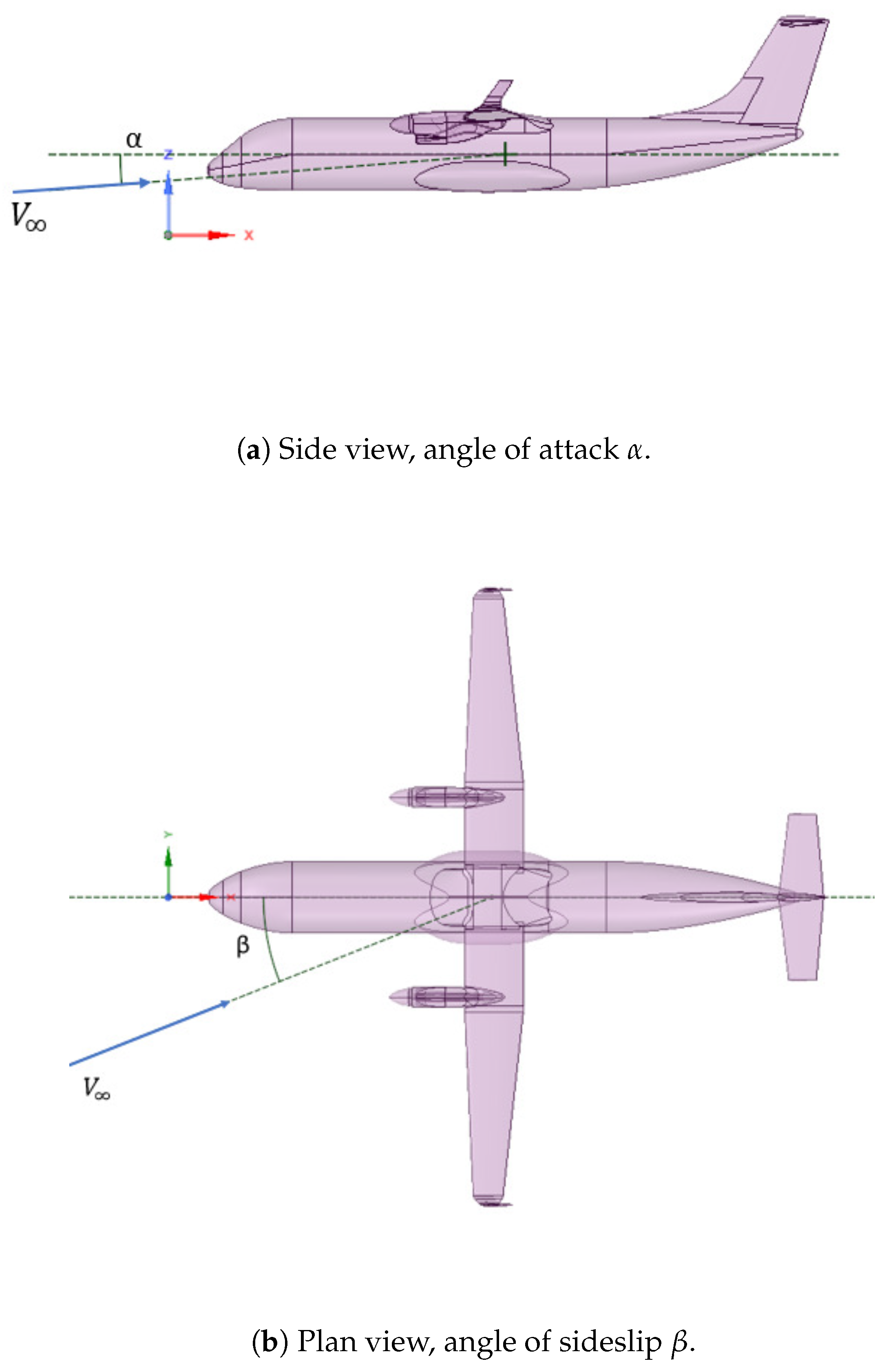
Figure 1. Aircraft side and plan views, angles of attack, and sideslip.
Aerospace 07 00068 g001
Figure 2. NLG: simplified geometric model.
Aerospace 07 00068 g002aAerospace 07 00068 g002b
Figure 3. MLG: simplified geometric model including bay, door, gear strut, and wheels.
Aerospace 07 00068 g003
Figure 4. MLG: angular position of the gear strut, from stowed to deployed configuration.
Aerospace 07 00068 g004
Figure 5. Computational sub-domains with active dynamic meshing.
Aerospace 07 00068 g005
Figure 6. NLG: initial computational mesh.
Aerospace 07 00068 g006
Figure 7. MLG: initial computational mesh.
Aerospace 07 00068 g007aAerospace 07 00068 g007b
Figure 8. NLG: computational mesh during the lowering phase (clockwise).
Aerospace 07 00068 g008
Figure 9. NLG: pressure distribution during the lowering phase (clockwise), for the case NLG–I.
Aerospace 07 00068 g009
Figure 10. NLG: skin friction distribution during the lowering phase (clockwise), for the case NLG–I.
Aerospace 07 00068 g010
Figure 11. NLG: time history of drag and lift coefficients for the gear strut and wheels.
Aerospace 07 00068 g011
Figure 12. NLG: time history of drag and lift coefficients for the downwind front door.
Aerospace 07 00068 g012
Figure 13. NLG: time history of drag and lift coefficients for the downwind rear door.
Aerospace 07 00068 g013
Figure 14. MLG: computational mesh during the lowering phase (clockwise).
Aerospace 07 00068 g014
Figure 15. MLG: pressure distribution during the lowering phase (clockwise), for the case MLG-I.
Aerospace 07 00068 g015
Figure 16. MLG: skin friction distribution during the lowering phase (clockwise), for the case MLG-I.
Aerospace 07 00068 g016
Figure 17. MLG: time history of drag and lift coefficients for the gear structure.
Aerospace 07 00068 g017
Figure 18. MLG: mean velocity contours at a given time instant.
Aerospace 07 00068 g018
Figure 19. MLG: time history of hinge moment coefficient for the doors.
Aerospace 07 00068 g019
Figure 20. MLG: time history of drag and lift coefficients for the doors.
Aerospace 07 00068 g020
Figure 21. Extrema of the scaled normal force on the doors for (left) NLG and (right) MLG simulations.
Aerospace 07 00068 g021
Table 1. Summary of different calculations presented with the number of FV cells.
Case α β # Cells
NLG–I1 M
NLG–II1 M
NLG–III5.7°2 M
MLG–I 2.5 M
MLG–II 2.5 M
MLG–III5.7°5 M