Abstract
Helicopter Emergency and Medical Service (HEMS) vehicles require a specially configured cabin that supports the quick transport of a rescue team to the site of an emergency and return of patients back to a full capacity hospital, while sustaining the patients’ health using specifically designed, but otherwise state-of-the-art life-support equipment. The effectiveness and safety of the service may be challenged by the vibratory level, which could be improved by optimally positioning the affected subjects within the cabin. However, the bare dynamical response of the airframe can lead to erroneous evaluation of vibration performance, since pilots, crew, patients, and medical equipment dynamically interact with the helicopter through their interfaces with the structure. Therefore, layout optimization of a HEMS vehicle for low vibration requires the capability to efficiently analyze a large set of candidate coupled helicopter-interface-subject configurations, reaching a suitable trade-off between model detail and computational cost. This work presents an effective vibration rating of medical helicopters to support vibration hazard reduction by minimization of cabin interior accelerations. The tool is able to model high-fidelity rotorcraft aeroservoelasticity, easily connect formulations representing the dynamics of humans, equipment, and their interfaces, and calculate the vibration performance of the resulting coupled models. The approach is applied to a medium-weight helicopter to find its lowest vibration HEMS configuration. It is demonstrated that the optimal positioning of HEMS subjects can significantly reduce vibration hazard and improve operation safety, nearly as effectively as the application of vibration attenuation solutions with a fixed cabin layout.
1. Introduction
Rotorcraft can operate in remote areas, where no airstrip is available and even where ground contact is not possible, thanks to their capability to hover or fly at very low airspeed, longitudinally and even sidewards, with the unique capability of taking-off and landing vertically (VTOL). Helicopter Emergency and Medical Service (HEMS) exploits this capability and provides effective and fast means of patient rescue, evacuation, and transportation. The clinical benefits of using helicopters in emergency medical service are well known and reported in literature (see, for example, Refs. [1,2,3]). However, the VTOL capability provided by rotors with high-speed rotating blades comes at the cost of poor vibration performance [4], which degrades comfort and safety. HEMS is not an exception and the people and equipment inside are affected, which are explained next.
1.1. HEMS Subjects and Related Risks
The health care equipment, pilots, patients, flight attendants, and medical crew are referred to as subjects of HEMS in this work. Each HEMS subject has specific response, posture, work-load, and vibration rating characteristics, thus each has specific potential safety and health risk increments.
1.1.1. Crew
HEMS operations are almost always operated with flight crew who are responsible for rescue and patient care. In short-term exposure, e.g., during a single rescue flight, vibration adversely affects rescue and health care tasks served to the patient, since stress level and cognitive task difficulty is likely to increase with vibration [5], thus reduced crew performance threatens patient safety. In the long term, crew are persistently exposed to vibrations, which frequently leads to back pain and contributes to several other health issues including digestive problems, higher blood pressure, and stress-related symptoms [6]. The usual posture is sitting and vibrations parallel to the spine, i.e., approximately in the vertical direction, are the main disturbing factor.
1.1.2. Pilots
The posture of the pilots is the same as that of the crew; therefore, the propagation of vibration and its consequences are similar in the long term. For example, in a recent survey, pilots reported that vibrations influenced their low-back and shoulder problems as a result of nerve compression and vertebrae misalignment [7,8]. Additionally, adverse effects of vibration are directly a flight safety problem for several reasons. First, whole-body vibration degrades visual acuity due to eye motion [9]. Second, vibrations on control sticks can degrade handling qualities [10]. More severely, the biodynamics of the pilot can couple with the vehicle vibrations, transmitting involuntary control inputs, which may cause closed loop instability in an otherwise stable system [11]. This coupling is more likely to happen when pilot workload is increased [12]. In fact, HEMS usually operate complex missions and are often required to perform the operation with tight margins whatever the flight condition is [13]. In particular flight conditions, bad weather, high-speed cruise, and night flight [14,15] may increase the pilot workload. Therefore, unless appropriate design mitigation actions are taken, vibration-induced adverse rotorcraft pilot coupling phenomena are more likely to happen in HEMS operations.
1.1.3. Patient
The mechanism of vibration transfer on a recumbent person is different than that of a seated occupant. The body is supported on a larger area than in the case of crew. However, the forces distributed along the body bend the spine, and may additionally cause rotation of the joints, especially of the neck. Furthermore, vibration of patients is not only a comfort problem, but also puts extra stress on them. It is reported that an increased vibrational level degrades the physiological and psychological condition [16], eases bleeding in patients with pelvic fractures [17], and has stressful effects on infants [18]. Therefore, vibrations can have drastic consequences on a patient’s health in HEMS, where persistent vibrations always exist.
1.1.4. Medical Equipment
High vibration levels affect reliability of any on-board equipment [19] and, as a result, reduce the availability of the vehicle. Similarly, medical equipment in HEMS also needs attention since some are vibration sensitive, especially those who carry numerous electronics on board, such as an automated external defibrillator [20]. Therefore, device functionality and handling can be adversely affected by vibrational levels, which can further increase the vibration hazards on the patient during pre-hospital care.
1.2. Vibration Rating
The evaluation of vibration hazard risks on HEMS subjects requires an accurate estimation of the accelerations received by each subject on-board. Therefore, HEMS vibration rating is not only a matter of measuring or calculating vibrations transmitted by the structure, but also a process that needs to take into account the dynamical characteristic of each subject. Vibration levels acting on engineered systems, such as medical equipment, can be sufficiently defined by acceleration amplitude and frequency. However, the human body senses vibration through visual, vestibular, somatic, and auditory systems, and combine all the signals to perceive the vibration level [6]. Therefore, the perception of vibration does not always correspond to the acceleration magnitude. For this reason, the actual acceleration needs to be scaled using empirical multipliers. In order to guide engineers, whole body vibration standards are developed. The most used ones are BS-6841 [21], ISO-2631 [22], NASA Ride Quality (RQ) [23], and Intrusion Index (II) [24]. Being more general, already applied to HEMS vibration assessment [25] and better reflecting the helicopter crew ratings [26,27], ISO-2631 is followed here.
In ISO-2631, human perception of vibration depends on the posture of the human body and excitation frequency. The first one is a function of how the vibration is transmitted to the human body. The multiplying factors in the three directions mentioned in ISO-2631 for seated, standing, and recumbent postures are reported in Table 1. The second factor, frequency weighting, is used to convert a nominal vibration amplitude in to the corresponding perceived level [6]. Figure 1 presents the ISO-2631 version of a human body frequency weighting. The plots include the cases of planar () and vertical () accelerations at the seat surface, acceleration of the seat back () that of motion sickness (), of body rotation (), and of the head of a recumbent person (). To understand the relation of the frequency weights with regard to HEMS rotorcraft, a shaded area indicating the typical range of main rotor excitation [28] is added to Figure 1. Special attention deserves the recumbent person, since the head sensitivity shows the highest possible sensitivity, which stays at its maximum level within the entire frequency range of interest. In comparison, the sensitivity of a seated human in vertical direction () drops from its maximum to about one third in the same frequency range.

Table 1.
ISO 2631-1 multiplying factors.
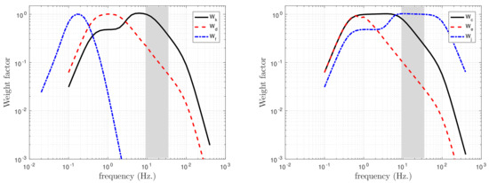
Figure 1.
Weighting factors of ISO-2631 standard with typical helicopter /rev frequency range is shaded. : seat-surface vertical direction, : seat-surface horizontal and lateral directions, : motion sickness, : seat-back, : rotational, : head of a recumbent person.
1.3. Scope
Much of the HEMS literature associated with vibrations is related to health and operational aspects. Recent advances include designing proper manikins for vibration evaluation [29], flight testing of HEMS operations [25,26], and simulating the supine posture of the patient’s body [30]. The studies focus on the experimental and numerical vibration analysis of the patient. However, the patient is only one of the concerns, although perhaps the most important, of HEMS safety as discussed above. Thus, an overall vibration evaluation of HEMS is still missing in literature. In addition, none of the mentioned studies provides clear indications about how to configure HEMS cabin interiors to minimize the effects of vibrations. Given their severe consequences, it is mandatory to effectively design HEMS cabin interior and the relative allocation of subjects.
HEMS cabin interior design by trial and error is not feasible when a large number of configurations is possible. Therefore, engineers have to rely on high-fidelity engineering models for a general solution of the problem (see Ref. [31] for a detailed history of rotorcraft specific methods). This is especially critical if experimenting is costly or unsafe, as in the case of HEMS. The present work addresses the absence of a proper method in the helicopter industry by presenting a novel approach for the accurate assessment of the overall vibration level of HEMS, including also vibration regulations such as ISO-2631. Using a fast and easy assembly of different HEMS layouts with the baseline vehicle, cabin interior design of HEMS configurations can be optimized to minimize the overall vibrational level.
2. Method
Achieving an optimum cabin layout design for HEMS missions cannot be considered a localized and independent task. While suffering from the same issues that are critical also for transport helicopters, several additional considerations arise. First of all, the length of a stretcher is usually above 2 , which is often comparable with the cabin width or length; thus, airframe deformation can induce different accelerations at different locations along the stretcher. This, in turn, may produce different responses at different parts of the patient’s body, which is less likely to occur for a seated occupant. Furthermore, equipment used in HEMS missions can be heavy, depending on the desired level of life support capability. Long and bulky equipment can interact with the airframe at multiple points; its impact on vehicle dynamics might not be negligible. Finally, the distribution of patient–stretcher and equipment, along with that of seated occupants, can easily spoil the symmetry of the structure. This is less critical in transport missions, where the distribution of occupants tends to be more uniform. As a result, the success of a modeling and analysis framework in HEMS vibration rating depends on:
- vehicle subcomponents (rotors, fuselage, etc.) formulated within their most natural modeling and analysis environment, which helps component engineers to focus on their task;
- high/uniform-fidelity overall modeling through sub-component assembly, thus a comprehensive analysis model is achieved within a shorter time;
- the capability of adding load paths between arbitrary structural points, which makes the definition of more accurate vibration performance formulations possible;
- exporting proper output models compatible for mounting medical equipment, human biodynamic models and corresponding interfaces, to support vehicle coupling with HEMS subjects;
- the capability of calculating the performance of the coupled design solutions, without the need to modify and reassemble the detailed baseline helicopter model, thus allowing engineers to find the optimum configuration among a variety of arrangements of medical equipment, recumbent patient, and seating occupants.
MASST (Modern Aeroservoelastic State Space Tools), is an aeroservoelastic simulation environment developed at Politecnico di Milano, which provides an efficient trade-off between complexity and versatility. Thanks to its proven vibration analysis capabilities [11,32], MASST satisfies the above criteria of the HEMS vibration rating. This section introduces MASST and explains how external dynamical models can be added to achieve a coupled system of the vehicle with crew, patient, and equipment, and describes how the resulting output is turned into vibration assessment functions.
2.1. Aeroservoelastic Rotorcraft Model
MASST analyzes compact, yet complete modular models of linearized aeroservoelastic systems [33,34]. Models are built from subcomponents collected using well-known, reliable and possibly state-of-the-art sources, which are blended together in a versatile mathematical environment. The equations of motion of the system are cast as first-order time differential equations. Each component is assembled in an overall model using the Craig–Bampton’s Component Mode Synthesis (CMS) approach [35]. The problem is formulated as a linear system in state-space form:
Vector contains the states of the system, contains the system output, the inputs and matrices , , and , matrices define the system. Considering the cases where system (Section 2.1) is asymptotically stable, it is possible to transform it into a transfer function between input and output vectors:
where s is the Laplace variable. Of course, in Equation (2), only controllable and observable states of Equation (1) are represented, but the asymptotic stability requirement ensures no problems with any remaining states.
The approximation represented by Equation (2) is valid whenever a linear approximation of a nonlinear system can be considered acceptable. The output response is proportional to the input and the matrices governing the system are constant. This assumption of linearity may cause under or over-estimation of the response in some cases, especially when limit or excessive loads are considered. When vibrations are the objective, the loads are normally well below limit operation static loads. Therefore, the linearity assumption can be considered valid in terms of load-response relations of a trimmed plant. However, in some cases, the system behaves linearly, but its parameters or the configuration of the helicopter change in time. These cases can still be handled efficiently in MASST, since matrices , , , can be highly parametric. The model in a generic configuration is interpolated from the corresponding linear models evaluated in the space of the parameters, such as rpm, advance ratio, weight, and center of mass position.
A virtual sensor and force, i.e., the capability to extract the kinematics of a point in space and apply the conjugated loads, can be defined at any physical FE-like node of the rotorcraft model. This is possible since each structural component model, including the airframe and the rotors, is represented by a Reduced Order Model (ROM) obtained using an appropriate generalized coordinate set, usually a combination of normal vibration modes and static shapes used to improve the description of lumped loads effects. The displacements and rotations of each node can be recovered through those shapes as functions of the state space vector, which contains the generalized coordinates of each structural component. Similarly, forces and moments can be defined on each node and introduced as generalized forces in the state space model. Vibrations at the sensor locations, as functions of the excitation forces, are evaluated in the state space formulation of the model. Moreover, the baseline high-fidelity model can be easily modified by assembling an additional dynamical system in the form of a feedback loop introducing the corresponding forces that depend on the kinematics exposed by the virtual sensors and thus augmenting the model with the dynamics of the added components, as explained in the next section.
2.2. Formulation of HEMS Subjects
The dynamical models of the HEMS subjects can be formulated using any suitable technique, considering the level of complexity, the available input data, and computational resources. Whichever technique is preferred, the model needs to be formulated in state-space form to be compatible with the previously described formulation of MASST, i.e.,:
in which vector contains the internal state of the subjects, and are their state-space matrices. The input of each subject is actually the output vector of the vehicle model, , whereas the output of the subject is the vector of the forces the subject applies to the vehicle. The notation can be made more compact by considering the transfer functions between the problem-specific input and outputs:
2.3. Combining Helicopter and Subjects
The vehicle and the subjects form a coupled system. The interface between the subjects and the vehicle feeds the subjects’ dynamic forces and moments , induced by the vibrations , back into the airframe model; in fact, the subjects’ dynamics might affect the magnitude of the induced acceleration. The accumulation of these modified accelerations might alter the overall comfort level as the number of passengers/crew increases, or heavy and asymmetrically positioned medical equipment is considered. Especially for a HEMS adaptation of a helicopter, the combined effect of human biodynamics, seat, and stretcher dynamics and the dynamics of the helicopter can only be evaluated during repeated trials and optimization. For this purpose, the use of a high-fidelity coupled model is essential for accuracy. However, the cost associated with the assembly of a detailed model of the entire vehicle, including the dynamic models of the subjects, is often not affordable when the number of trials increase. For this reason, an effective design method could take advantage of a platform for high-fidelity aeroservoelastic modeling of rotorcraft, which should allow the vibration engineer to modify the dynamics of a baseline plant by adding equipment, stretcher, and human feedback models, but without the need to re-assemble the baseline vehicle model when the configuration is modified.
MASST can export models with proper force-sensor relations such that feedback loops of the arbitrary type can be added to a nominal model. In a general sense, the dynamical models of equipment, stretcher, and human body can be considered as feedback elements that operate from the output of virtual sensors and produce the corresponding input as external forces. According to Figure 2:
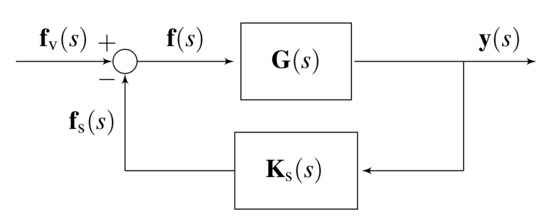
Figure 2.
Block diagram representation of the base vehicle, , and subject feedback, .
- The input for the helicopter model is defined as the vibratory forces and moments applied at any airframe point and/or on the rotors. Typically, these loads originate from main and tail rotors and are transferred to the fuselage through the rotor hubs.
- The output of the helicopter model is chosen as the sensors of position, velocity, and acceleration of any airframe point, or rotor point in multiblade coordinates; thus, it is a linear function of the state and input of the model.
- The subjects create a feedback loop between the sensors corresponding to the motion and the forces exerted by the subjects () at their attachment points,such that the total force can be expressed as , where the negative feedback convention is used. The transfer matrix represents the synthesis of the subject’s state-space representation described in Section 2.2.
Then, the response of the modified system is obtained as:
where matrix is the dynamic compliance matrix of the MASST high fidelity tool given in Equation (2) ( is the output of the baseline helicopter model, with ). The gain matrix can be easily formulated using force–response relationships of the attached device or human vibration model. Once this relation is defined, the dynamics of the human subjects, stretcher, and medical equipment may be coupled with the helicopter model, regardless of their level of complexity.
2.4. Processing Vibration Signals
Acceleration at a generic point is expressed in time domain (t) as:
which refers to the acceleration of HEMS subjects. In order to apply frequency weights, a discrete Fourier transform () is performed:
where is the acceleration vector in the frequency domain:
After applying frequency (Figure 1) and direction weights (Table 1), the frequency-weighted acceleration is formally obtained as:
which can be truncated for practical reasons, depending on the relative magnitudes of each harmonic. The ratings are given in terms of root mean square of the magnitude of the weighted acceleration over the exposure time T:
Note that frequency weightings are defined for human subjects; in case of medical equipment, they are set to unity, unless provided by the manufacturer.
2.5. Vibration Index
To achieve a quantitative vibration rating, the root mean square value of frequency-weighted accelerations of HEMS subjects is considered along with the human sensitivity multipliers and relative importance weights of the subjects. A vector is defined, which includes the root mean square (rms) magnitudes of the frequency weighted accelerations of each subject:
where is the frequency-weighted acceleration of the ith pilot for (typically 1 or 2); is the acceleration of the ith crew member for (usually 1, 2 or more); is the acceleration of the ith patient for (typically 1, occasionally 2); is the acceleration of the ith equipment for (usually of the same order of magnitude of the other parameters). Then, the vibration index (VI) is defined as a weighted quadratic matrix multiplication:
The weight matrix is block diagonal; it consists of the relative costs given to the different groups of subjects:
where , , , and represent the costs given to pilots, crew, patients, and equipment vibration, respectively. The selection of these values is not arbitrary, since they can significantly influence the outcome. For example, an identity matrix, gives equal weight to each subject. Alternatively, the VI can be biased towards one type of subject, say patient, for instance, by setting a higher value to its cost than that of others. While selecting a proper , trying several alternatives or perturbing the individual costs can help judging the initial selection and evaluate the sensitivity of the VI.
3. HEMS Model
This section explains how a proper HEMS vibration analysis model is built on top of a high-fidelity baseline helicopter model by adding properly selected HEMS subjects. The same model is used in Section 4 when the method is demonstrated.
3.1. Baseline Helicopter
The high-fidelity baseline helicopter model is built based on data representative of a generic, medium weight (6.5 ton) helicopter with a conventional articulated 5 blade main rotor and tail rotor configuration. A snapshot of the physical kinematic variables of the helicopter model is shown in Figure 3. The model includes:
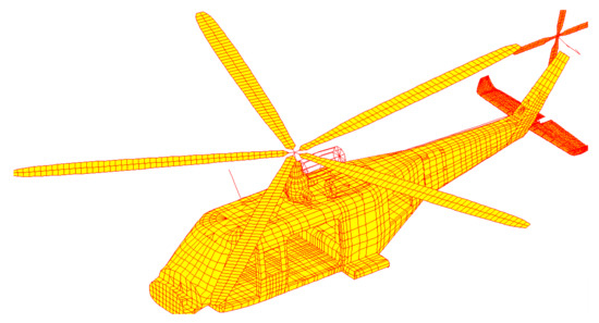
Figure 3.
Physical degrees of freedom of the baseline helicopter model.
- six rigid body degrees of freedom;
- the airframe stability derivatives, calculated from the aerodynamic look-up tables of the fuselage, horizontal and vertical tail using CAMRAD/JA (a comprehensive rotorcraft analysis software [36]), which are required to capture the low-frequency flight mechanics behavior of the helicopter;
- the elastic bending and torsion modes of the airframe in a frequency range up to 50 Hz to include modes up to twice the rotor excitation frequency of 25 Hz. The modes are extracted from a NASTRAN (a popular Finite Element solver) detailed finite element model which. The model is characterized by more than 30,000 nodes and 17,000 elements. The elements include beams (for the main and tail rotor blades and main skeleton of the fuselage), shells (for the fuselage skin), and bricks (for non-structural parts);
- proportional structural damping, which is superimposed in MASST to the airframe portion of the model
- main and tail rotor aeroelastic models, computed using CAMRAD/JA and characterized by two bending modes (the first in lead-lag and the second in flap, typical of soft in-plane articulated rotors) plus one torsion mode (related to the control chain compliance), formulated in multiblade coordinates. The models represent the rotors at a specific maximum load flight condition. However, MASST allows for including multiple models (parametrized for example by flight speed, density, etc.), and find the corresponding model at a prescribed condition by means of interpolation.
- an axial dynamic inflow model, based on Pitt–Peters’ formulation (Ref. [37]) acting on the main rotor;
- the transfer functions of the main and tail rotor servoactuators, directly formulated in Matlab/Simulink, considering servo-valve and dynamic compliance [38]; a matrix of gear ratios is used to convert the linear actuator displacements into collective and cyclic commands;
- the nodes and coordinates for the sensors and the forces, which correspond to physical degrees of freedom, are directly defined in MASST.
3.2. Occupant in Sitting Posture
Pilots, medical, and rescue crew, and passengers usually travel in a helicopter in sitting posture. Vibrations are transmitted to the body by the seat surface, footrest, and handles. The human body reacts to those vibration sources, resulting in acceleration levels different from that of the cabin floor. A simplified approach of studying biodynamic response to vibratory input is to post-process measured accelerations at the contact interface (see Ref. [39] for a detailed summary of whole body vibration experiments). However, this precludes feeding back the dynamic forces produced by the subject to the vehicle dynamics, a task that requires a mathematical model of the vehicle.
The lumped parameter, finite element and multibody dynamics modeling techniques have gained acceptance in human biodynamics, mainly differing in the level of detail, versatility, and required input data [40]; all of them can be handled within MASST [41]. To present an example of the infrastructure for vibration rating, a lumped human model is considered in this work, since nonlinear and more complex models do not lead to significant changes when whole body vibration is calculated at the seat surface [41]. Among many others [42], the model proposed by Wan and Schimmels [43] is a classical four degree of freedom lumped model of human body vibration with linear springs and dampers that idealize the connections between the body parts.
The sitting subjects are generally connected to the cabin floor by a seat and a cushion. The seat is described as a mass, which is supported by a suspension composed of a spring and a damper. The cushion can significantly alter the comfort of an occupant [44], and hence is included as a massless spring-damper. The seat–cushion parameters are adapted from a helicopter application [45]. The combined seat–human system, as illustrated in Figure 4, is excited through the seat support by the floor motion . The equations of the seating occupant are cast in the form of Equation (3) and added to the baseline helicopter model. The numerical values of the parameters are reported in Table 2.
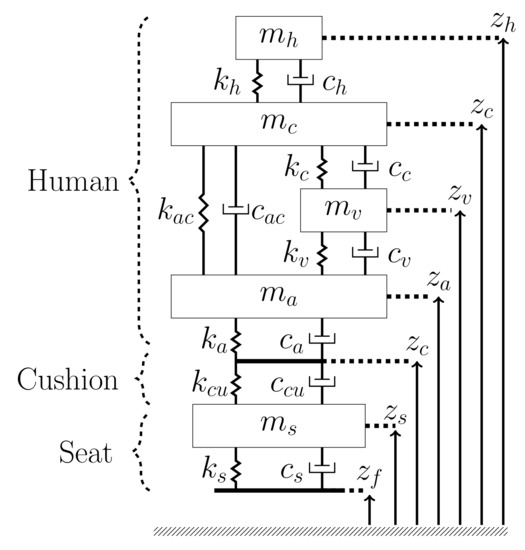
Figure 4.
Wan–Schimmels lumped pilot model [43] sitting on a cushion supported by a lumped seat–cushion model [45].

Table 2.
Numerical values for the Wan–Schimmels Model [43] and seat–cushion model [45].
The vertical accelerations are measured at the seat surface, as suggested in ISO-2631. It is worth mentioning that the proposed methodology can support increasingly complex biodynamics models [41], and respond to recent considerations about the comfort and health degradation due to vibrations of other body parts. For example, head accelerations [46] can be critical in helicopters due to the increasing use of helmets and night vision systems [47].
3.3. Patient
The usual form of patient transportation is by securing them in a lying position on a stretcher. In this posture, the loads change along the human body due to the deformation of the airframe, which excites the patient through the surface of the stretcher, bending the skeleton, and rotating the articulations. Therefore, the formulation of the patient–stretcher model should include bending and rotation of body segments [48].
Similar to the formulation of the seated occupant, a model for the lying patient can be developed using the lumped parameter, finite element, and multibody dynamics approaches Although nonlinear and more complex models for the recumbent patient may lead to different values of acceleration for the subject, no comparison is available. Therefore, a lumped model obtained from the literature is used for the recumbent human biodynamics without loss in generality, since the proposed framework can handle increasingly complex biodynamic models. As presented in Figure 5, the patient body is formulated based on an inclined 9 degree of freedom model [49], which reduces to six degrees of freedom when the subject is lying horizontally and only vibrations perpendicular to the stretcher plane are considered. The model degrees of freedom consist of translation and rotation of head (, ), upper body (, ), and lower body (, ). The connections between each degree of freedom are modeled as springs and dampers. The upper and lower body have additional flexibility along the frontal axis, whereas the head is rigid.
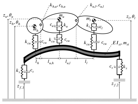
Figure 5.
A 6-DOF recumbent human biodynamic model, resting on a cushion supported by an elastic stretcher.
The stretcher is composed of a cushion and litter; it can significantly change vibration exposure compared to a patient lying on a rigid floor [50]. The patient’s body rests on a massless cushion which is modeled as a 1-DOF spring and damper distributed all over the litter, having the same properties that of the seat (, ). The litter is modeled as a one-dimensional Euler–Bernoulli beam, formulated using the finite element method. It has a uniform cross section and is supported by a spring and damper suspension at the two ends, which uses the same values of the seat. The flexural rigidity and mass distribution are estimated using a simplified geometry of the steel frame given in Figure 6 and a mass of litter with the external dimensions reported in Ref. [51]. Uniform mass distribution is assumed; the thickness of the circular bars is estimated from the mass and the external dimensions of the litter.
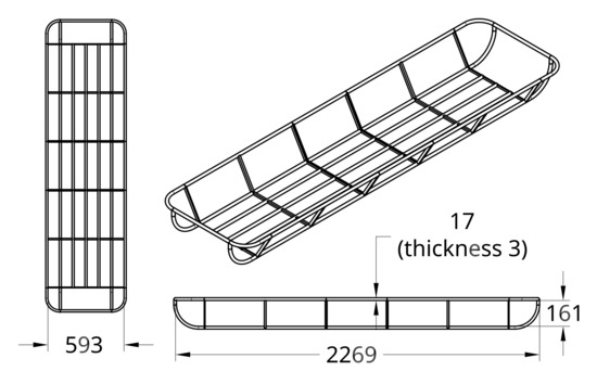
Figure 6.
A simple metal frame idealization representative of an evacuation litter for the estimation of flexural rigidity.
The stretcher is assumed to be attached to the cabin floor at the two ends using elastic supports, which are assumed identical to those of the seat–cushion data (, ) given in Table 2. The combined patient–cushion–stretcher system is excited through the motion of the floor at the connection points ( and ). The patient–stretcher coupled equations are cast in the form of Equation (3) and added to the baseline helicopter model. The numerical values used in this work are reported in Table 3.

Table 3.
Parameters of recumbent person and its interface.
3.4. Medical Equipment
Although more complex finite element models can be handled by the proposed approach, a rigid model resting over two elastic supports is considered in this work for the medical equipment. As shown in Figure 7, the body has rotational and translational degrees of freedom and is assumed to be excited through the cabin floor. The equations of the rigid equipment equations are cast in the form of Equation (3) and added to the baseline helicopter model. The stiffness and damping values of the support and cushion, (, ), are assumed to be equal to those of the seat data given in Table 2. The assumed data are specified in Table 4.
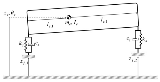
Figure 7.
Assumed geometry of a rigid medical equipment on supports.

Table 4.
Parameters of the rigid equipment.
3.5. Vibration Source
Rotor loads, fuselage aerodynamics, engine, and transmission contribute to the vibrations in the cabin [28]. Among those, main rotor loads at the blade passage frequency ( or in a non-dimensional form as /rev, for being the number of blades and is the rotor angular speed.) are intrinsically and persistently produced when in non-axial flow conditions, e.g., in forward flight. Their amplitude usually exceeds by far any other source of vibration. For this reason, the magnitude of /rev can be considered as the main criterion of vibration performance assessment in helicopters [27], which is also reported for HEMS [26]. Therefore, without loss in generality, the main rotor is considered as the only source of vibratory loads in this work, although noticing that an arbitrary number of vibration sources can be handled by the proposed method. In order to define a realistic vibratory load case, measured values representative of the axial elongations of the gearbox suspension struts of a medium-weight helicopter at at a blade passage frequency of is used. The data measured at different flight conditions are converted into equivalent hub loads. The most critical forces acting on the main rotor hub are estimated by comparing the magnitude of the forces in the struts. The corresponding values are reported in Table 5 relative to take-off weight (TOW).

Table 5.
Maximum estimated hub force components at /rev frequency relative to take-off weight. The phase of the excitation force was not available, and assumed to be zero in the analysis.
3.6. Vibration Attenuation Devices
Active and passive vibration attenuation device implementation is still extensively used by the helicopter industry to achieve favorable vibrational levels [28]. Active systems are used for producing counter-acting vibratory loads, whereas semi-active and passive systems are preferred to isolate the vibration sources and components. The proposed cabin layout optimization aims at the same goal; therefore, the application of the method proposed in this work can be tested against a similar helicopter model, modified with a conventional vibration alleviation solution. For this purpose, a passive spring-mass device in parallel to the gearbox struts is selected. The device is composed of a beater mass located between two springs, which are mounted at the two terminals of the struts, as presented in Figure 8. The mass–spring pair is tuned for the stiffness of the gearbox struts added to the baseline helicopter in the form given in Section 2.2.
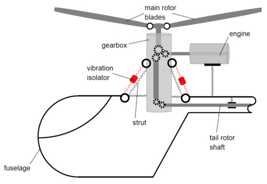
Figure 8.
Mass–spring vibration isolators on gearbox struts.
4. Analysis, Results, and Discussion
This section demonstrates the benefits of using a modeling environment for HEMS missions in vibration rating estimation, and presents how to achieve an optimal HEMS cabin interior layout adaptation of an existing rotary-wing platform.
4.1. Configuration Optimization
To demonstrate the optimization of HEMS cabin interior design, eight possible structural locations for mounting seats, a stretcher, and a piece of medical equipment are defined, as illustrated in Figure 9. The objective is to find the optimal configuration of those eight locations. The constraints reported below are considered:

Figure 9.
Distribution and Labels of cabin attachment points.
- each seat shall be mounted on a single point, two for the pilot and co-pilot, and two for the crew;
- the seats of pilot and co-pilot are fixed at 1L and 1R; both are always considered occupied and included in the optimization;
- the stretcher is aligned laterally (which is safer in case of crash [52]), and shall be mounted on the floor at its two ends;
- the equipment shall be aligned longitudinally, and mounted on two points, one of which adjacent to the head of the patient;
- The crew shall sit adjacent to the equipment and to each other.
These constraints result in the possible configurations reported in Figure 10. The baseline helicopter is assumed to carry only pilot and co-pilot.
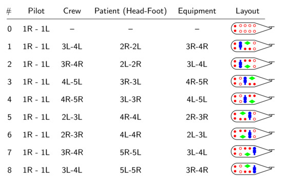
Figure 10.
Assumed possible configurations used to demonstrate the vibration rating of a medical helicopter.
It is assumed that there are two pilots, two medical and rescue crew, one patient lying on a stretcher, and one piece of medical equipment. The output vector includes the variables and consists of frequency-weighted vertical accelerations of these subjects:
where and is the acceleration of each pilot at the seat surface; and is the acceleration of each crew at the seat surface; is the average of the sum of the acceleration at the cushion surface under the head, upper body, and lower body segments; is the acceleration of the center of gravity of the equipment. The objective function of the optimization is referred to as vibration index (VI):
where:
To illustrate the sensitivity of the relative weights on the vibration performance, four values of the cost matrix are used. The pilots are present in all optimization cases and always included in the cost matrix. However, an independent pilot-focused optimization is not included since the pilot seat locations cannot be modified. Consequently, the cost matrices that affect the other elements are reported in Table 6. They respectively give equal cost to all elements (1), or focus on patient (2), crew (3), or equipment (4). An on–off approach is used by setting the weights either to 1 or 0, while those weights can take any value. The first cost matrix is used for a comparative study of the eight mentioned HEMS configurations of Figure 10. The other ones are used to show how the choice of the cost matrix changes the least vibratory solution.

Table 6.
Cost matrices used in demonstration.
The proposed approach is suitable for a broad variety of optimization techniques, since it can handle arbitrary parametric and topological modifications to a baseline plant. However, in the present case, the total number of configurations is limited. Therefore, brute-force optimization is preferred, which guarantees an absolute minimum. In other words, the objective function in Equation (16) is simply calculated for all the possible configurations of Figure 10, and the resulting values are compared to find the optimum solution.
Finally, it should be noted that additional constraints can be applied on individual accelerations, for example setting a limit to pilot seat acceleration, or, instead of using a single VI, a multi-objective optimization can be formulated. Such improvements are possible and should be used when necessary, since they can significantly change the optimum layout. However, within the scope of this work, we preferred an overall VI formula without any individual constraints on subjects.
4.2. Results and Discussion
Figure 11 presents the vibration index () and the acceleration of each subject for the eight possible configurations defined in Figure 10 for equally weighted subjects of: (i) the baseline helicopter, referred to as “nominal”, and (ii) one modified by adding the vibration absorber of Section 3.6, referred to as “modified”. All results are normalized with those of the nominal one. Since an increased means a higher overall vibratory level, for both the nominal and the modified plant, configuration 7 shows the smallest VI for the defined HEMS mission, whereas configuration 4 is the least successful.
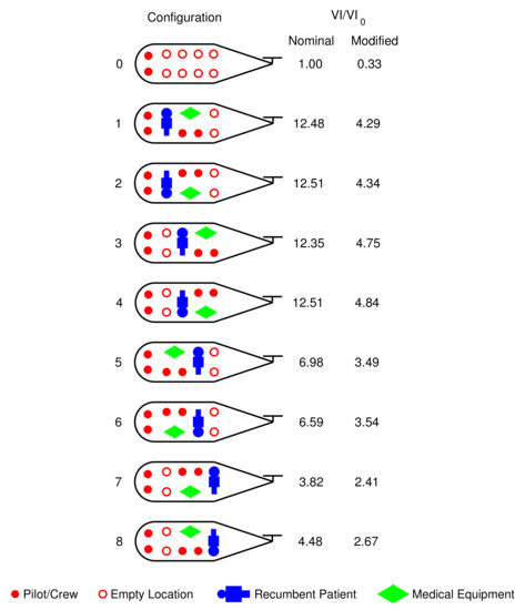
Figure 11.
Vibration index of the possible configurations of crew, patient stretcher, and equipment of nominal plant and modified plant with mass-spring absorber when all subjects are given equal weight. Results are normalized with respect to the nominal baseline configuration.
The effect of the vibration alleviation device is remarkable. The vibration index in the modified helicopter is always significantly less than in the nominal design for the same cabin layout. However, an interesting conclusion can be drawn in favor of cabin layout design: optimizing the cabin layout without the cost (design, weight, maintenance, etc.) of adding a vibration alleviation device can lead to lower overall vibrational level than simply applying vibration alleviation devices with a prescribed cabin layout. For example, configuration No. 7 of the nominal helicopter has lower vibrational level than configuration No. 4 of the modified helicopter, and similar considerations apply to all configurations from No. 1 to No. 4 of the modified helicopter. Moving the patient one row aft is at least as effective as adding a vibration alleviation device on a prescribed HEMS configuration. This shows that the proposed method can either save the cost associated with adding a vibration alleviation device, or lead to lower vibration when simultaneously designing cabin interior and vibration alleviation devices.
Figure 12 shows the best configurations when an alternative use is made of the subject weights: when the different costs of Table 6 are applied in the evaluation of the vibration index of the nominal and modified helicopters, the optimal HEMS layout changes. The baseline and best (“Equal weights”) configurations of Figure 11 are repeated for comparison. For the nominal plant, there appears a tendency to place the subject under consideration in the last row. However, as can be seen in the “Two crew” case, this does not happen for the modified plant. Moreover, one subject can dominate the others, as can be inferred from the identical layouts that resulted for “Equal weights” and “Patient” optimizations in the nominal plant.
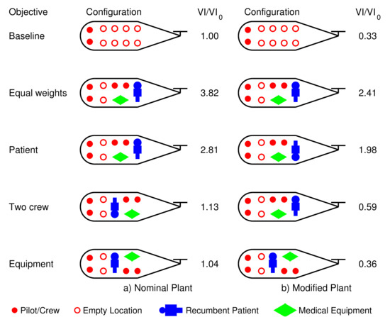
Figure 12.
The subject-focused HEMS layouts with least vibration indices of nominal plant and modified plant with mass-spring absorber. Results are normalized with respect to nominal baseline configuration.
The presence of a vibration absorber changes the optimal configurations achieved using different objectives. However, the modified plant with an absorber has a lower overall VI as compared to the nominal one regardless of the objective. The optimal layouts obtained for nominal and modified plants are not necessarily the same, as can be seen for the two-crew only case shown in Figure 12. This shows how, if both layout optimization and the inclusion of vibration devices are planned for HEMS, it would be better to optimize the layout in the presence of the vibration device to achieve the least possible VI.
The accelerations of the individual points are not included in the results, since the scope is to achieve an overall reduction in vibration. However, it should be emphasized that an overall objective, such as the VI of Equation (16), can result in an increase of the acceleration for individual subjects. This aspect needs attention if there are prescribed limits for any of the subjects, which can be a requirement set by HEMS operators in case of human patients or operators of medical equipment. In case such limits have to be considered, constraints on individual responses can be defined or a multi-objective optimization problem should be considered instead of a single VI.
5. Conclusions
This work presented the use of an aeroservoelastic analysis framework for evaluating vibration rating of medical helicopters and helping to achieve least vibrating HEMS configurations. The rotorcraft community, significantly HEMS rotorcraft manufacturers and operators, can benefit from this novel approach and the reported findings to achieve lower levels of vibration in emergency medical service operations. In brief, the proposed method presents the following advantages over standard rotorcraft analysis tools:
- it provides a high-fidelity analysis tool for rotorcraft, assembling subcomponents which are modeled in their most natural platform, which is instrumental for accurate estimation of vibrations;
- without spoiling and re-assembling the baseline helicopter model, the dynamical models of typical HEMS occupants and components can be included in the vibration analysis, their position can be modified, and vibration performance formulations can be fine-tuned. This reduces the set-up time and speeds up the optimization process of a HEMS configuration;
- a large number of possible HEMS configurations can be quickly evaluated; hence, optimum solution is found, and the effects of differently weighting each subject’s accelerations can be investigated effectively;
- different types of helicopters, unconventional HEMS configurations, and complex dynamical models of humans, equipment, seats, and stretchers can be easily handled;
The method is illustrated using a model representative of a 6.5 ton medium-weight helicopter and standard models for seating occupants’ vibratory response, seats compliance, dynamics of a recumbent patient on an elastic stretcher, and rigid equipment on flexible mounts. From the numerical results, the following suggestions can be made to reduce vibration related hazards in HEMS:
- the larger the number of HEMS configurations allowed by the cabin structure increases, the more likely it is to achieve a low-vibration HEMS cabin layout;
- the relative weights of HEMS subjects can yield different cabin layouts; therefore, the relative importance of the subjects should be carefully defined;
- for HEMS, optimizing the cabin layout can be as effective as mounting vibration absorbers, but without the related weight penalty and maintenance cost;
- The application of vibration attenuation devices in HEMS is effective the most when accompanied by the cabin interior layout design, since they may have comparable impact.
Author Contributions
Conceptualization, A.T. and P.M.; Formal analysis, A.T. and V.M.; Funding acquisition, G.Q. and P.M.; Investigation, A.T.; Methodology, V.M., G.Q., and P.M.; Software, G.Q.; Supervision, G.Q. and P.M.; Validation, A.T.; Writing—original draft, A.T.; Writing—review & editing, A.T., V.M., G.Q., and P.M. All authors have read and agreed to the published version of the manuscript.
Acknowledgments
This work received partial support from the Leonardo Helicopter Division. The authors particularly acknowledge Leonardo Helicopter Division for providing part of the data used in the analysis.
Conflicts of Interest
The authors declare no conflict of interest.
References
- Floccare, D.J.; Stuhlmiller, D.F.E.; Braithwaite, S.A.; Thomas, S.H.; Madden, J.F.; Hankins, D.G.; Dhindsa, H.; Millin, M.G. Appropriate and Safe Utilization of Helicopter Emergency Medical Services: A Joint Position Statement with Resource Document. Prehospital Emerg. Care 2013, 17, 521–525. [Google Scholar] [CrossRef]
- Sullivent, E.E.; Faul, M.; Wald, M.M. Reduced Mortality in Injured Adults Transported by Helicopter Emergency Medical Services. Prehospital Emerg. Care 2011, 15, 295–302. [Google Scholar] [CrossRef]
- Ausserer, J.; Moritz, E.; Stroehle, M.; Brugger, H.; Strapazzon, G.; Rauch, S.; Mair, P. Physician staffed helicopter emergency medical systems can provide advanced trauma life support in mountainous and remote areas. Injury 2017, 48, 20–25. [Google Scholar] [CrossRef]
- Watkinson, J. Art of the Helicopter; Elsevier, Butterworth-Heinemann: Oxford, UK, 2004. [Google Scholar]
- Ljungberg, J.K.; Neely, G. Stress, subjective experience and cognitive performance during exposure to noise and vibration. J. Environ. Psychol. 2007, 27, 44–54. [Google Scholar] [CrossRef]
- Mansfield, N. Human Response to Vibration; CRC Press: Boca Raton, FL, USA, 2005. [Google Scholar]
- Harrer, K.L.; Yniguez, D.; Maria, M.M.; Ellenbecker, D.; Estrada, N.; Geiger, M. Whole Body Vibration Exposure for MH-60S Pilots; Naval Medical Center San Diego (NMCSD): San Diego, CA, USA, 2005. [Google Scholar]
- Chafé, G.S.; Farrell, P.S.E. Royal Canadian Air Force CH-146 Griffon Aircrew 2014 Spinal Musculoskeletal Trouble Survey; Scientific Report DRDC-RDDC-2016-R179; DRDC–Toronto Research Centre: Toronto, ON, Canada, 2016. [Google Scholar]
- Griffin, M.J. Eye Motion during Whole-Body Vertical Vibration. Hum. Factors 1976, 18, 601–606. [Google Scholar] [CrossRef]
- Masarati, P.; Quaranta, G.; Gennaretti, M.; Serafini, J. An Investigation of Aeroelastic Rotorcraft-Pilot Interaction. In Proceedings of the 37th European Rotorcraft Forum, Paper No. 112. Vergiate/Gallarate, Italy, 13–15 September 2011. [Google Scholar]
- Quaranta, G.; Tamer, A.; Muscarello, V.; Masarati, P.; Gennaretti, M.; Serafini, J.; Colella, M.M. Rotorcraft Aeroelastic Stability Using Robust Analysis. CEAS Aeronaut. J. 2014, 5, 29–39. [Google Scholar] [CrossRef]
- Muscarello, V.; Masarati, P.; Quaranta, G.; Lu, L.; Jump, M.; Jones, M. Investigation of Adverse Aeroelastic Rotorcraft-Pilot Coupling Using Real-Time Simulation. In Proceedings of the American Helicopter Society 69th Annual Forum, Paper No. 193. Phoenix, AZ, USA, 21–23 May 2013. [Google Scholar]
- Special Investigation Report on Emergency Medical Services Operations; Aviation Special Investigation Report PB2006-917001; National Transportation Safety Board: Washington, DC, USA, 2006.
- Baker, S.P.; Grabowski, J.G.; Dodd, R.S.; Shanahan, D.F.; Lamb, M.W.; Li, G.H. EMS Helicopter Crashes: What Influences Fatal Outcome? Ann. Emerg. Med. 2006, 47, 351–356. [Google Scholar] [CrossRef]
- Hinkelbein, N.J.; Schwalbe, H.V.G. Helicopter emergency medical services accident rates in different international air rescue systems. Open Access Emerg. Med. 2010, 45–49. [Google Scholar] [CrossRef]
- Kubo, M.; Terauchi, F.; Aoki, H.; Matsuoka, Y. An investigation into a synthetic vibration model for humans:: An investigation into a mechanical vibration human model constructed according to the relations between the physical, psychological and physiological reactions of humans exposed to vibration. Int. J. Ind. Ergon. 2001, 27, 219–232. [Google Scholar] [CrossRef]
- Carchietti, E.; Cecchi, A.; Valent, F.; Rammer, R. Flight Vibrations and Bleeding in Helicoptered Patients with Pelvic Fracture. Air Med. J. 2013, 32, 80–83. [Google Scholar] [CrossRef]
- Björn-Markus, K.; Marie, L.; Markus, L.; Marcus, K.; Ronnie, L.; Stellan, H.; Urban, W.; van den Berg, J. Sound and vibration: Effects on infants’ heart rate and heart rate variability during neonatal transport. Acta Paediatr. 2011, 101, 148–154. [Google Scholar] [CrossRef]
- Veca, A. Vibration Effects on Helicopter Reliability and Maintainability; TM 73-11; NASA: Washington, DC, USA, 1973. [Google Scholar]
- Wu, J.; Zhang, R.R.; Radons, S.; Long, X.; Stevens, K.K. Vibration analysis of medical devices with a calibrated FEA model. Comput. Struct. 2002, 80, 1081–1086. [Google Scholar] [CrossRef]
- Measurement and Evaluation of Human Exposure to Whole-Body Mechanical Vibration; Technical Report BS-6841; British Standard Institution: London, UK, 1987.
- ISO. ISO Mechanical Vibration and Shock-Evaluation of Human Exposure to Whole-Body Vibration; Technical Report ISO2631-1; ISO: Geneva, Switzerlands, 1997. [Google Scholar]
- Leatherwood, J.D.; Clevenson, S.A. A Design Tool for Estimating Passenger Ride Discomfort within Complex Ride Environments. J. Hum. Factors Ergon. Soc. 1980, 22, 291–312. [Google Scholar] [CrossRef]
- Anonymous. Requirements for Rotorcraft Vibration Specifications, Modeling and Testing; ADS-27A; US Army AMCOM: Redstone Arsenal, AL, USA, 2006. [Google Scholar]
- Smith, S.D.; Chervak, M.S.; Steinhauer, M.B. Special Investigation Report on Emergency Medical Services Operations; Technical Report AFRL-RH-WP-TR-2014-0053; Air Force Research Laboratory: Wright-Patterson AFB, OH, USA, 2014. [Google Scholar]
- Chen, Y.; Ghinet, S.; Price, A.; Wickramasinghe, V.; Grewal, A. Evaluation of Aircrew Whole-Body Vibration Exposure on a Canadian CH-147F Chinook Helicopter. J. Am. Helicopter Soc. 2017, 62, 1–11. [Google Scholar] [CrossRef]
- Rath, T.; Fichter, W. A Closer Look at the Impact of Helicopter Vibrations on Ride Quality. In Proceedings of the AHS 73rd Annual Forum, Fort Worth, TX, USA, 9–11 May 2017. [Google Scholar]
- Johnson, W. Rotorcraft Aeromechanics; Cambridge University Press: Cambridge, UK, 2013. [Google Scholar]
- Acosta, K.K.S. The Comparison of Two Supine Manikins and the Use of a Shock and Vibration Isolation System for Litter Patients in Air Medical Support. Master’s Thesis, The University of Nevada, Las Vegas, NV, USA, 2015. [Google Scholar]
- Khaksar, Z.; Anavatti, S.; Ceruti, A.; Shankar, K. The Simulation of Vibration at the Supine Patient’s Body in HEMS. In Proceedings of the 9th Australasian Congress on Applied Mechanics, Sydney, Australia, 27–29 November 2017. [Google Scholar]
- Johnson, W. A History of Rotorcraft Comprehensive Analyses; TP 2012-216012; NASA: Washington, DC, USA, 2012. [Google Scholar]
- Tamer, A.; Muscarello, V.; Masarati, P.; Quaranta, G. Evaluation of vibration reduction devices for helicopter ride quality improvement. Aerosp. Sci. Technol. 2019, 95, 105456. [Google Scholar] [CrossRef]
- Masarati, P.; Muscarello, V.; Quaranta, G. Linearized Aeroservoelastic Analysis of Rotary-Wing Aircraft. In Proceedings of the 36th European Rotorcraft Forum, Paris, France, 7–9 September 2010; p. 099. [Google Scholar]
- Masarati, P.; Muscarello, V.; Quaranta, G.; Locatelli, A.; Mangone, D.; Riviello, L.; Viganò, L. An Integrated Environment for Helicopter Aeroservoelastic Analysis: the Ground Resonance Case. In Proceedings of the 37th European Rotorcraft Forum, Vergiate/Gallarate, Italy, 13–15 September 2011; pp. 177.1–177.12. [Google Scholar]
- Craig, R.R., Jr.; Bampton, M.C.C. Coupling of Substructures for Dynamic Analysis. AIAA J. 1968, 6, 1313–1319. [Google Scholar] [CrossRef]
- Johnson, W. CAMRAD/JA, A Comprehensive Analytical Model of Rotorcraft Aerodynamics and Dynamics; Johnson Aeronautics Version; Johnson Aeronautics: Palo Alto, CA, USA, 1988. [Google Scholar]
- Pitt, D.M.; Peters, D.A. Theoretical Prediction of Dynamic-Inflow Derivatives. Vertica 1981, 5, 21–34. [Google Scholar]
- Merritt, H.E. Hydraulic Control Systems; John Wiley & Sons: New York, NY, USA, 1967. [Google Scholar]
- Rakheja, S.; Dong, R.; Patra, S.; Boileau, P.E.; Marcotte, P.; Warren, C. Biodynamics of the human body under whole-body vibration: Synthesis of the reported data. Int. J. Ind. Ergon. 2010, 40, 710–732. [Google Scholar] [CrossRef]
- Mohajer, N.; Abdi, H.; Nahavandi, S.; Nelson, K. Directional and sectional ride comfort estimation using an integrated human biomechanical-seat foam model. J. Sound Vib. 2017, 403, 38–58. [Google Scholar] [CrossRef]
- Tamer, A.; Zanoni, A.; Muscarello, V.; Cocco, A.; Quaranta, G.; Masarati, P. Biodynamic Modeling Techniques for Rotorcraft Comfort Evaluation. Aerotec. Missili Spaz. 2019. [Google Scholar] [CrossRef]
- Bai, X.X.; Xu, S.X.; Cheng, W.; Qian, L.J. On 4-degree-of-freedom biodynamic models of seated occupants: Lumped-parameter modeling. J. Sound Vib. 2017, 402, 122–141. [Google Scholar] [CrossRef]
- Wan, Y.; Schimmels, J.M. Optimal seat suspension design based on minimum simulated subjective response. J. Biomech. Eng. 1997, 119, 409–416. [Google Scholar] [CrossRef] [PubMed]
- Ciloglu, H.; Alziadeh, M.; Mohany, A.; Kishawy, H. Assessment of the whole body vibration exposure and the dynamic seat comfort in passenger aircraft. Int. J. Ind. Ergon. 2015, 45, 116–123. [Google Scholar] [CrossRef]
- Choi, Y.T.; Wereley, N. Biodynamic Response Mitigation to Shock Loads Using Magnetorheological Helicopter Crew Seat Suspensions. J. Aircr. 2005, 42, 1288–1295. [Google Scholar] [CrossRef]
- Rahmatalla, S.; DeShaw, J. Predictive discomfort of non-neutral head–neck postures in fore–aft whole-body vibration. Ergonomics 2011, 54, 263–272. [Google Scholar] [CrossRef]
- Law, A.H.; Beatty, H.E.W.; Keillor, J.; Wickramasinghe, V. Pilot Head and Neck Response to Helicopter Whole Body Vibration and Head-Supported Mass. In Proceedings of the AHS 73rd Annual Forum, Fort Worth, TX, USA, 9–11 May 2017. [Google Scholar]
- Rahmatalla, S.; DeShaw, J.; Barazanji, K. Biodynamics of supine humans and interaction with transport systems during vibration and shocks. J. Low Freq. Noise Vib. Act. Control. 2019, 38, 808–816. [Google Scholar] [CrossRef]
- Cho, Y.; Yoon, Y.S. Biomechanical model of human on seat with backrest for evaluating ride quality. Int. J. Ind. Ergon. 2001, 27, 331–345. [Google Scholar] [CrossRef]
- DeShaw, J.; Rahmatalla, S. Predictive discomfort of supine humans in whole-body vibration and shock environments. Ergonomics 2016, 59, 568–581. [Google Scholar] [CrossRef]
- Lifesaving Systems Corp. Online Catalog. Available online: http://lifesavingsystems.com/store/lifesaving_catalog/mobile/index.html#p=5 (accessed on 9 February 2020).
- Weinberg, W.T. Aircraft Litter Retention Design Criteria; Technical Report AD632457; USAAVLABS: Fort Eustis, VA, USA, 1990. [Google Scholar]
© 2020 by the authors. Licensee MDPI, Basel, Switzerland. This article is an open access article distributed under the terms and conditions of the Creative Commons Attribution (CC BY) license (http://creativecommons.org/licenses/by/4.0/).