Article

Detection and Prognosis of Propagating Faults in Flight Control Actuators for Helicopters

Department of Mechanical and Aerospace Engineering, Politecnico di Torino, 10129 Torino, Italy
*
Author to whom correspondence should be addressed.
Aerospace 2020, 7(3), 20; https://doi.org/10.3390/aerospace7030020
Submission received: 20 December 2019 / Revised: 29 January 2020 / Accepted: 24 February 2020 / Published: 26 February 2020
(This article belongs to the Special Issue Fault Detection and Prognostics in Aerospace Engineering)

Abstract

:
Recent trend in the aeronautic industry is to introduce a novel prognostic solution for critical systems in the attempt to increase vehicle availability, reduce costs, and optimize the maintenance policy. Despite this, there is a general lack of literature about prognostics for hydraulic flight control systems, especially looking at helicopter applications. The present research was focused on a preliminary study for an integrated framework of fault detection and failure prognosis tailored for one of the most common architectures for flight control actuation. Starting from a high-fidelity dynamic model of the system, two different faults were studied and described within a dedicated simulation environment: the opening of a crack in the coils of the centering springs of the actuator and the wear of the inner seals. Both failure modes were analyzed through established models available in the literature and their evolution simulated within the model of the actuator. Hence, an in-depth feature selection process was pursued aimed at the definition of signals suitable for both diagnosis and prognosis. Results were then reported through an accuracy-sensitivity plane and used to define a prognostic routine based on particle filtering techniques. The more significant contribution of the present research was that no additional sensors are needed so that the prognostic system can be potentially implemented for in-service platforms.

1. Introduction

Aeronautic systems are the most frequent cause of unpredicted interruptions of aircraft availability, and a relevant fraction of failures can be traced down to the actuation devices. The development of novel prognostic techniques for such systems, aimed at enabling condition-based maintenance policies, is hence of significant interest within the optics of reducing aircraft downtimes and its associated costs, optimizing the logistics of spare parts, and increase as much as possible the aircraft availability. The latter is of particular interest for helicopters, which have been the subject of studies on advanced health monitoring since the beginning of the research on prognostics [1]. Helicopters come with some interesting characteristics that make them a natural choice for prognostics-related studies. On-board equipment tends to degrade faster than their counterparts in the fixed-wing vehicle due to the extremely stressful vibratory environment, resulting in lower values of mid-time-between failures. The literature on prognostics and health management (PHM) on helicopters has so far been centered around the structural monitoring of the power transmission elements, conveying the mechanical energy produced by the engine to the main and tail rotors [2,3].
Little-to no references can be found on flight control systems, and most of the prognostics works on flight control systems are made on electromechanical actuators [4,5]. While some information could be deducted from a few papers pursuing PHM for the hydraulic actuation technologies most commonly adopted for large passengers’ aircraft [6,7], the architecture of the flight control actuator usually employed in a helicopter is starkly different from those used in fixed-wing configurations. As such, not only different failure modes may arise or not be present, while similar degradations could lead to different effects on actuator behavior. At the same time, some features proven for fixed-wing flight control actuators could be incomputable on helicopters due to the different sensors set usually equipped on the actuation system [8].
We presented in this paper a first study on the prognosability of flight control systems for helicopters, based on the classical configuration of hydraulic actuation with mechanical feedback and stability and control augmentation systems (SCAS). At first, the architecture of the actuator was introduced, and the function of each component underlined. A paramount step to pursue a rigorous study of the system behavior under nominal and degraded health conditions is the definition of a statistically representative database of data [9]. In the absence of a long and expensive experimental campaign, we chased this objective through a high-fidelity physical model of the system, whose underlying equations were experimentally validated, comprehensive of theoretically inferred degradations model. Hence, extensive simulation campaigns counting more than 100 simulations each were performed, both in healthy and faulty conditions, following the approach already used by authors in [7]. It permitted to generate a statistically-representative number of simulations under different, growing levels of degradation that granted to build a reference database for the prognostic analysis. In order to pledge the statistical variance of the results, all of the possible uncertainty sources (i.e., electrical disturbances on the servovalves’ current and LVDT’s voltage and uncertainties on fluid properties and spring geometry) were characterized and inserted within the simulation model. Hence, features for each considered fault mode were selected based on accuracy and sensitivity criteria [10]. The selected features were used within a data-driven framework based on an advanced declination of particle filtering to pursue fault detection and prognosis. Results were, hence, investigated through traditional metrics of the PHM field.

2. System Configuration and Physical Model

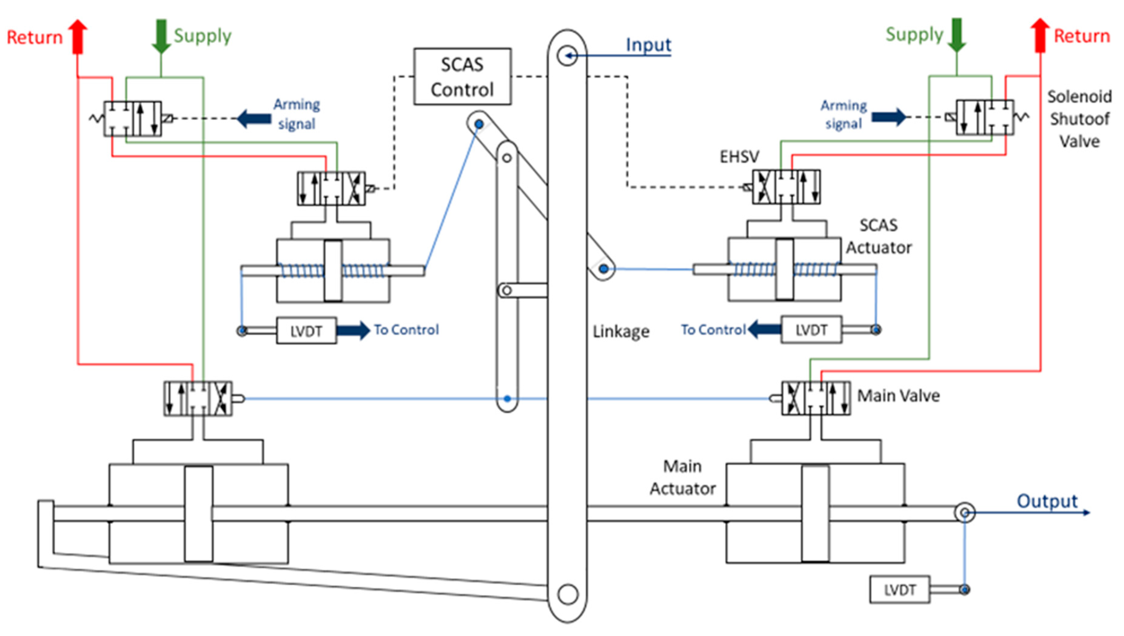
2.1. System Configuration

The reference architecture for the study presented in this paper is depicted in Figure 1, where one of the actuators controlling the collective and the cyclic pitch of the main rotor is represented. The pilot input acted on the central linkage that established the position of the main control valves spool. The main control valves commanded the tandem hydraulic actuator, which was connected to the stationary swashplate, while the position feedback of the hydraulic actuator was purely mechanical and exercised through the linkage. Two SCAS actuators acted on the linkage as well; controlled through two servovalves, the SCAS actuators had limited authority over the position of the main actuator, and their main use was to stabilize the helicopter when subjected to particularly demanding aerodynamic conditions, such as low-height hovering, flight nearby vertical walls, heavy gusts environment, and so forth. As shown in Figure 1, SCAS actuators had two centering springs, which kept the actuator in a neutral position in the absence of command. Each SCAS was equipped with at least one LVDT used to measure the rods’ positions and to close the control loop. Given this traditional architecture, the avionics only collected the signals associated with the servovalve currents and the SCAS actuator position. Any PHM system would have, hence, to deal with the low number of available signals.

2.2. Physical Model

A high-fidelity physical model was developed, and a complex set of differential equations was implemented in order to reproduce the dynamical behavior of the system. The aim was carried out both in healthy and faulty conditions. The healthy physical model of the actuator was derived from the experimentally validated set of equations provided by authors in [11]. The models describing the presence and the progression of a few selected fault cases were instead defined ex-novo. In particular, two of the most critical failure modes affecting the SCAS actuator were studied—the opening of a crack in one of the centering spring and the wear of the inner seals of the hydraulic actuator.

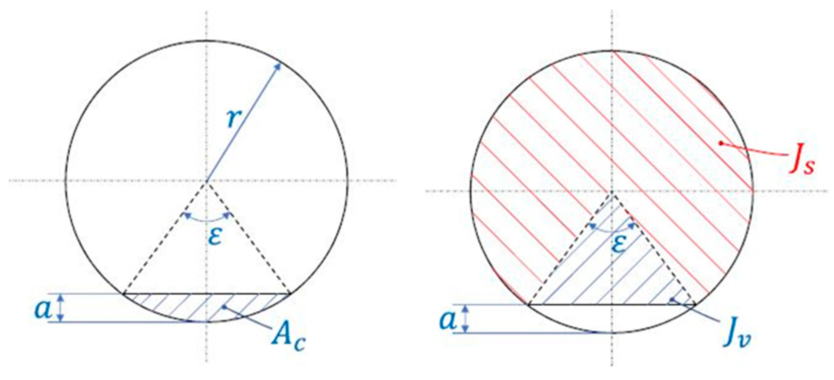
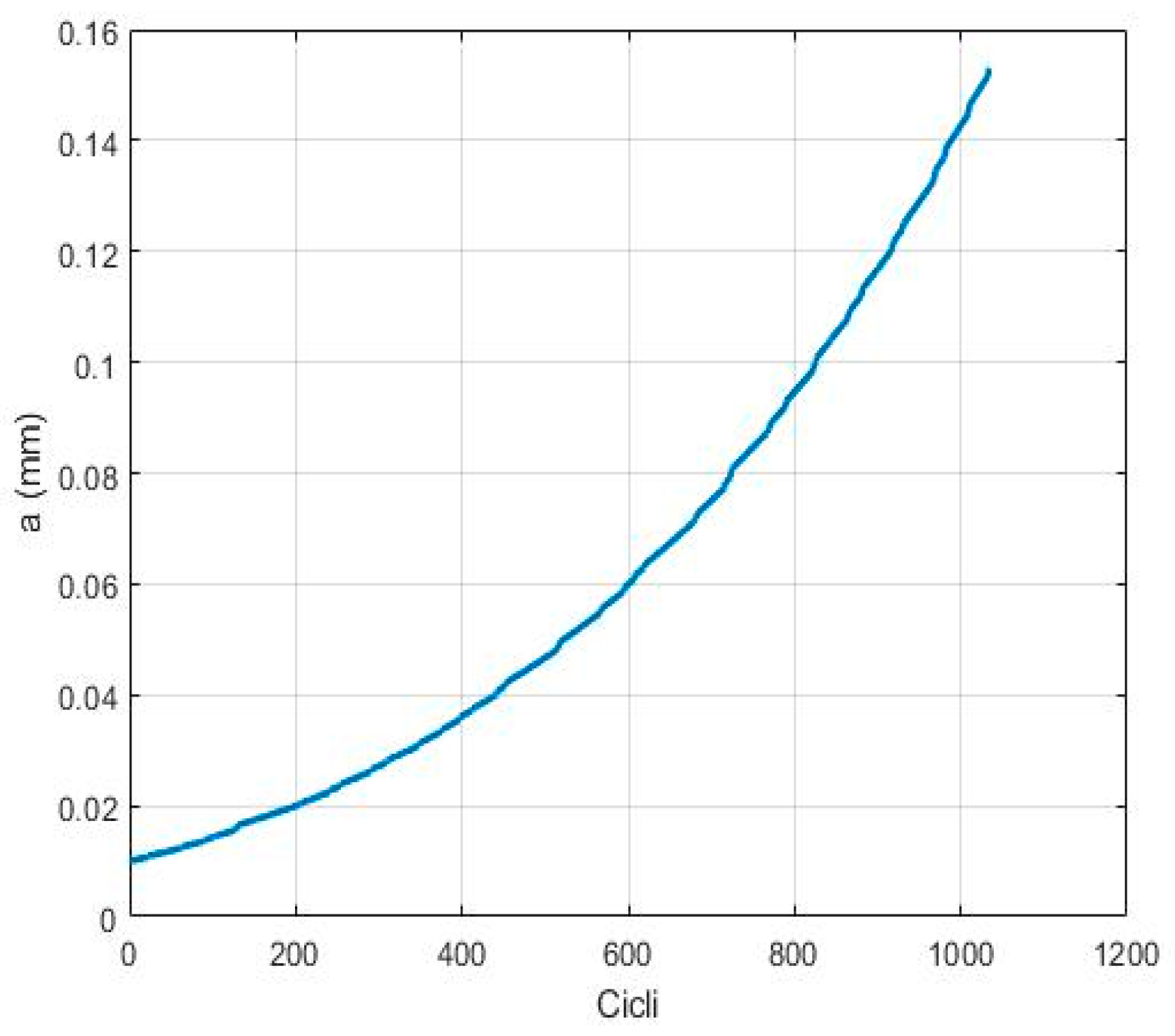
2.2.1. Spring Cracking

SCAS centering springs are two compression helical springs with a small spring index. As pointed out in [12], in these kinds of springs, fatigue cracks always nucleate at the surface and propagate under torsion in a direction inclined of 45° with respect to the spring wire axis. Therefore, the presence of a surface crack on the inside of one coil was considered; the examined shape is shown in Figure 2.
The crack modified the stiffness of the spring that is given by the series of the N coils as,
1 K = i = 1 N 1 K i = K h   K f K h + K f
where K h is the stiffness of ( N 1 ) healthy coils, and   K f is the stiffness of the faulty coil. Starting from the maximum stress equation for springs [13]:
τ m a x = F   R   r J + F A  
where F is the force acting on the spring,   R and r are, respectively, the radius of spring coil and of the spring wire, J is the polar second moment of inertia, and A is the resistant area of the coil. Combining Equation (2) with Hooke’s law, we obtained,
K f = τ max δ   ( R   r J + 1 A )  
the displacement δ is geometrically linked to the maximum shear strain γ max through the spring index C and the shear modulus G .
τ max G = γ max = δ 2   π   R 2   C + 1 2   C 2
No plastic deformation within the coil was assumed. Combining Equations (3) and (4), an explicit expression for the stiffness of the faulty coil could be obtained.
K f = G   ( 2 C + 1 ) 2   C 2 π D ( R   r J + 1 A )
As shown in Figure 2, the presence of a crack modified the polar second moment of area ( J ) that could be computed by the linearity of integration and the resistant area ( A ). Then, the connection between the depth of the crack and these two quantities could be expressed as,
{ ε = 4   arcsin a 2   r     A = π r 2 A c = π r 2 r 2 2 ( ε sin ε   ) J = J s + J v = ( 2   π ε ) r 4 4 + r 2 sin sin   ( ε 2 ) ( r a ) 3
Please refer to Figure 2 and to Symbols section for the parameters involved in the above equation. The reduction of the spring stiffness and the crack depth could, under these assumptions, be considered directly proportional, as shown in Figure 3.
Considering the faulty coil as a beam subjected to a torsional strain, the stress intensity factor for the edge of the crack could be computed as,
K III = π 2 τ max F T ( η ) r
where η = a / ( 2   r ) is the dimensionless crack depth, and F T ( η ) is a geometrical factor given by [14]. Reversing this equation and replacing K III with its critical value associated with the brittle failure of the coil, it was possible to compute the critical value of crack depth at which fracture occurred ( a c ). Also, the critical value of crack depth at which plastic collapse occurred ( a p ) was computed. The final value of crack depth associated with the failure conditions was, hence, the minimum between these two quantities. Crack growth was computed by Paris’ Law [15], combined with the Rainflow method; results obtained for one of the considered cases are shown in Figure 4.

2.2.2. Seals Wear

The occurrence of wear of the actuator piston seals implied a progressive increase of the internal leakages. To model the thickness of the removed material ( λ ), we resolved to apply the well-known Archard’s law [16], which states
λ ( t ) = L a ( t ) β   A c
where L a is the friction work, β is a constant of the employed materials, and A c is the contact area between the piston seal and the barrel. The internal leakages were supposed to be directly proportional to the pressure differential across the two chambers Δ p . Considering both laminar and turbulent leakage flows, the total flow loss due to leakage was,
Q l = K i 1 Δ p + K i 2 | Δ p | sign ( Δ p )
where K i 1 and K i 2 are two leakage coefficients, both function of λ ( t ) .
Figure 5 shows that the cut-off frequency of the system is inversely proportional to leakage coefficients. Critical values of these two coefficients were defined as the values at which the cut-off frequency was 10% lower with respect to the healthy condition one.

3. Scenario Definition and Simulation

In order to preserve the simulations variability and to allow a suitable statistical analysis, all of the most significant uncertainty sources were described within the model. In particular, Gaussian noise describing electrical disturbances was applied over the servovalve currents of the SCAS and on the LVDT’s voltage on the secondary windings. The same was pursued for the supply pressure, where it was introduced to simulate the fluctuations due to changes in the behavior of the hydraulic system not present in the model. Moreover, the properties of the hydraulic fluid were described as a function of the fluid temperature and air fraction, both variable within the simulations, while geometrical tolerances were considered in the definition of the spring geometry and mechanical behavior. Each above-mentioned variable was supposed to have a mean value and a variance, in order to describe the uncertainty on the functions. The pdf (probability density function) chosen to describe the distribution around the mean value was a normal one. Two main operating conditions were considered: complete mission profiles and dedicated, and pre-flight on-ground test. Both conditions are hereby detailed.

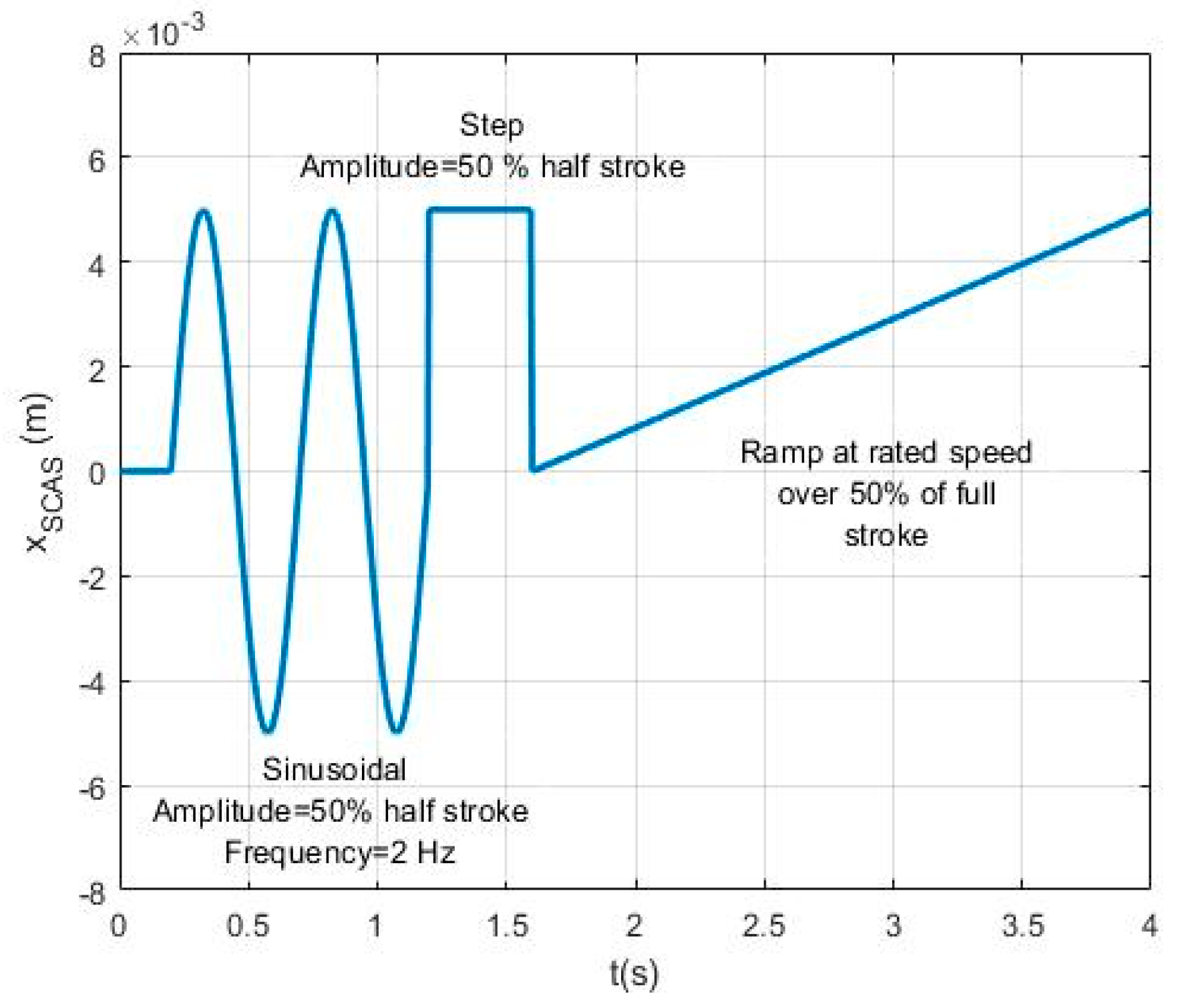
3.1. On-Ground Tests

To highlight the presence of faults, which might be difficult to observe during flights, authors proposed the use of a dedicated set of commands to be provided to the actuators prior to each flight [17]. Several tests were performed on the ground by applying the position command to the SCAS actuator reported in Figure 6, in the absence of any pilot command.

3.2. In-Flight Conditions

Mission profiles for helicopters are extremely variable and difficult to predict a-priori since they heavily depend on the purpose of the mission, its objectives, and the environmental conditions encountered while flying relatively close to the ground. A simplified model was employed in which SCAS and pilot commands were combinations of the sinusoidal signals of Table 1, plus a possible random variation of variance equal to 10% of the reported amplitude values. Although simplistic in the description of the pilot input, this assumption could be considered realistic for SCAS actuators since their main purpose was to enforce the horizontal stability of the vehicle, mostly against oscillatory behaviors. Signals were combined, guaranteeing command continuity and preserving the frequency of occurrence of each command. The external force was defined in a similar way, though it must be noted that the influence of the external force over the behavior of the SCAS actuator was expected to be minimal since its presence affects only the equilibrium of the main actuator.

4. Feature Selection

Feature selection is the process that aims to exploit a certain combination of signals to determine the best possible indexes associated with the studied fault modes among a pool of candidates. Theoretically, a feature should exhibit a high correlation with the on-going fault severity, a high value of signal-to-noise ratio, and low dependency on all the other possible fault modes. More than 100 simulations were performed for eight growing levels of fault severity, ranging from health conditions to catastrophic failure, all while considering the presence of external disturbances and noise, as defined in Section 5. From the preliminary analysis conducted in this study, only two out of three available signals were proven to be useful to pursue this aim, namely the servovalve currents and the SCAS actuator position. The main actuator position was largely unaffected by issues occurring within the SCAS system, so this signal was not considered. By focusing on the remaining two signals, the effects of their introduction within the system could be observed. In particular, the opening of a crack in the actuator spring caused an asymmetry in the elastic force applied to the actuator, which had to be compensated by continuously operating the servovalve, whose currents, hence, exhibited a growing null-bias, as shown in Figure 7a. Seals wear, on the other hand, caused a reduction of the servo system gain due to the loss of hydraulic energy, as depicted in Figure 7b.
These considerations laid down the physical basis to define a significant number of feature candidates, reported in Table 2, both for on-ground (G) and in-flight (I) simulated data sets.
Defining the feature candidates, a preliminary analysis was done to eliminate redundant elements from the pool by applying the Kullback–Leibler divergence to each possible couple of candidates [18]. As a result, candidates I5 and I6 were deemed redundant, and I5 removed due to complexity issues.
To select the best features from the considered pool of candidates, four metrics were considered. The correlation between each candidate and the fault severity, the signal-to-noise ratio, the accuracy or probability of a correct response, as defined in [19], and the average severity at detection was obtained by applying a data-driven fault detection algorithm, presented in Section 5, to the considered degradation paths. The results of the feature selection process are depicted in Figure 8, where the candidates are ranked as a function of the severity at detection, accuracy, and correlation coefficient. The radius of each data point was proportional to the signal-to-noise ratio.
Therefore, the best features for spring cracking under the hypothesis of the presented study were G3 (on-ground) and I2 (in-flight), while for seals wear, they were G3 (on-ground) and I6 (in-flight). G3 was affected by both fault modes but showed opposite behavior on their occurrences (it grew for crack openings, decreased in response to leakages). As such, it was considered suitable in the first approximation under the hypothesis of the absence of multiple concurrent degradations.

5. PHM Algorithm

5.1. Fault Detection

A purely data-driven approach was chosen to pursue fault detection. Following this method, the selected features were continuously computed and compared to baseline conditions: the fault was declared when the 95% of the running distribution of one of the features overcame the 95th percentile of its baseline distribution defined for health conditions. Although simple, this technique is widely reported in dedicated literature for its robustness, simplicity of implementation, and extremely low computational requirements. As already shown in Figure 8, the average fault severity at detection over the considered degradation path was 25% of the critical level for the crack opening case and 9% for the wear of the piston seals.

5.2. Failure Prognosis

The final aim of any PHM algorithm was to predict the behavior of the remaining useful life (RUL) of the faulted component, meaning to provide probability distribution of the possible time of failure coupled with indication on the risk of failure. We pursued this goal through an advanced declination of particle filtering, whose complete logic is described in [20]. Particle filters or Sequential-Monte-Carlo techniques are a class of algorithm based on Bayesian inference suitable for non-linear tracking problems affected by non-Gaussian noise [21,22], which have, hence, found a natural application in prognostics [23]. The prognostic framework takes advantage of a nonlinear process (fault/degradation) model, a Bayesian estimation method using particle filtering and real-time measurements. The estimate of the fault severity is achieved by performing two sequential steps—prediction and filtering. The prediction uses both the knowledge of the previous state estimate and the process model to generate the a priori state pdf estimate for the next time instant,
p ( x 0 : t | y 1 : t 1 ) = p ( x t | y t 1 ) p ( x 0 : t 1 | y 1 : t 1 ) dx 0 : t 1
Particle filters are used to numerically solve Equation (10) in real by approximating the state pdf using samples or “particles” having associated discrete probability masses (“weights”) as,
p ( x t | y 1 : t ) w ˜ t ( x 0 : t i ) δ ( x 0 : t x 0 : t i ) dx 0 : t 1
where x 0 : t i is the state trajectory, and y 1 : t are the measurements up to time t . Weights are, hence, resampled once the features computed from the field are made available. We employed a fast and simple resampling scheme based on sequential importance resampling, which updates the weights based on the likelihood. Long-term predictions were then performed by iterating the prediction step, Equation (11), until meeting failure conditions. It was, hence, possible to estimate the distribution of the remaining useful life and compute the associated risk of failure, as proposed in [24]. An example of the output provided by such a framework is reported in Figure 9, where the algorithm was applied to the case of a crack in the actuator spring. Performances of the prognostic algorithm were evaluated through the traditional metrics proposed in [25]. In particular, the relative accuracy (RA) and cumulative relative accuracy (CRA), both derived from the α-λ analysis, were evaluated. These metrics showed prognostics’ effectiveness for both faults. The relative accuracy for the opening of a crack in the spring coils never fell below 80% over the course of the whole degradation process, while the one related to the wear of the seals always remained over 90%. The final value of CRA for the crack opening was 86%, while for the worn seals was 94%. Both results suggested confidence in the selected features, which provided a reliable forecast of the RUL over the performed simulations, provided that more fault cases need to be investigated to assess their robustness.

6. Conclusions

There are presently no papers in literature explicitly dedicated to flight control actuators for helicopters, despite the criticality of this component. Under the hypothesis of only one fault occurring at a time, this paper presented a few features suitable for use to detect the presence of a crack in the SCAS actuators springs and the wear of the inner seals of the same actuators. Moreover, those same features proved to be suitable for prognostics analysis. Although more fault modes need to be investigated to fully assess its merits, the proposed systems provided encouraging results towards the opportunity of realizing a comprehensive PHM system for flight control actuators without the need for additional sensors. Moreover, the structure of the study is easily extendable to the introduction of other fault modes. Further developments would consist of injecting additional faults (e.g., backlash in linkage’s hinge), evaluating possible fault classification schemes, and possibly corroborating theoretical results through experimental tests.

Author Contributions

Conceptualization, supervision, G.J.; conceptualization, supervision, writing, review, and editing, A.D.M.; methodology, simulation, data analysis, and writing, A.N.; conceptualization, supervision, M.S. All authors have read and agreed to the published version of the manuscript.

Funding

This research received no external funding.

Conflicts of Interest

The authors declare no conflict of interest. The funders had no role in the design of the study; in the collection, analyses, or interpretation of data; in the writing of the manuscript, or in the decision to publish the results.

Abbreviations

CRACumulative relative accuracy
FFTFast Fourier Transform
LVDTLinear Variable Differential Transformer
PHMPrognostics and health management
pdfProbability density function
RARelative accuracy
RMSRoot Mean Square
RUL Remaining useful life
SCASStability and command augmentation system

Symbols

aDepth of crack, m
AArea, m2
CSpring index R/r, dimensionless
DDiameter of the spring coil, m
FAxial force action on the spring, N
FT(η)Geometrical factor, dimensionless
GShear modulus, Pa
iCurrent, A
JPolar second moment of area, m4
KSpring stiffness, N/m
Ki1First leakage parameter, m3/s/Pa
Ki2Second leakage parameter, m3/s/ P a
KIIIStress intensity factor, Pa m
LaFriction work, J
NNumber of spring turns, dimensionless
QlVolumetric flow rate, m3/s
RRadius of the spring coil, m
rRadius of the spring wire, m
xDisplacement, m
βExperimental material parameter, N/m
γShear strain, dimensionless
ΔpDifferential pressure, Pa
δSpring displacement, m
εOpening angle of the crack, rad
ηDimensionless crack depth a/(2r)
λThickness of removed material, m
τShear stress, Pa

References

  1. Keller, J.; Carr, D.; Love, F.; Grabill, P.; Ngo, H.; Shanthakumaran, P. AH-64D Main Transmission Accessory Drive Spur Gear Installation Fault Detections. J. Intell. Manuf. 2012, 23, 205–211. [Google Scholar] [CrossRef]
  2. Blunt, D.M.; Keller, J.A. Detection of a fatigue crack in a UH-60A planet gear carrier using vibration analysis. Mech. Syst. Sig. Process. 2006, 20, 2095–2111. [Google Scholar] [CrossRef]
  3. Pawar, P.M.; Ganguli, R. Helicopter rotor health monitoring-A review. Proc. Inst. Mech. Eng. Part G J. Aerosp. Eng. 2007, 221, 631–647. [Google Scholar] [CrossRef]
  4. Brown, D.; Georgoulas, G.; Bole, B.; Pei, H.L.; Orchard, M.; Tang, L.; Saha, B.; Saxena, A.; Goebel, K.; Vachtsevanos, G. Prognostics Enhanced Reconfigurable Control of Electro-Mechanical Actuators. In Proceedings of the Annual Conference of the Prognostics and Health Management Society PHM09, San Diego, CA, USA, 27 September–1 October 2009. [Google Scholar]
  5. Dalla Vedova, M.D.L.; Germanà, A.; Berri, P.C.; Maggiore, P. Model-Based Fault Detection and Identification for Prognostics of Electromechanical Actuators Using Genetic Algorithms. Aerospace 2019, 6, 94. [Google Scholar] [CrossRef] [Green Version]
  6. Byington, C.S.; Watson, M.; Edwards, D. Data-Driven Neural Network Methodology to Remaining Life Predictions for Aircraft Actuator Components. In Proceedings of the 2004 IEEE Aerospace Conference, Big Sky, MT, USA, 6–13 March 2004. [Google Scholar]
  7. Autin, S.; Socheleau, J.; Dellacasa, A.; De Martin, A.; Jacazio, G.; Vachtsevanos, G. Feasibility Study of a PHM System for Electro-Hydraulic Servo- Actuators for Primary Flight Controls. In Proceedings of the Annual Conference of the Prognostic and Health Management Society, Philadelphia, PA, USA, 1 September 2018. [Google Scholar]
  8. Jacazio, G.; Mornacchi, A.; Sorli, M. Development of a prognostics and health management system for electrohydraulic servoactuators of primary flight controls. In Proceedings of the 5th International Workshop on Aircraft System Technologies AST2015, Hamburg, Germany, 24–25 February 2015. [Google Scholar]
  9. Roemer, M.; Byington, C.; Kacprszynski, G.; Vachtsevanos, G.; Goebel, K. Prognostics. In Systems Health Management with Aerospace Applications; Wiley: Hoboken, NJ, USA, 2011. [Google Scholar]
  10. Vachtsevanos, G.; Lewis, F.; Roemer, M.; Hess, A.; Wu, B. Intelligent Fault Diagnosis and Prognosis for Engineering Systems, 1st ed.; Wiley: Hoboken, NJ, USA, 2007. [Google Scholar]
  11. De Martin, A.; Dellacasa, A.; Jacazio, G.; Sorli, M. High-Fidelity Model of Electro-Hydraulic Actuators for Primary Flight Control Systems. In Proceedings of the BATH/ASME 2018 Symposium on Fluid Power and Motion Control, Bath, UK, 12–14 September 2018. [Google Scholar]
  12. Shiwaku, K.; Yamada, Y.; Koarai, J.; Kawaguchi, Y. Improvement of Fatigue Life of Valve Spring Wire by Reducing Non-Metallic Inclusions. SAE Trans. 1985. [Google Scholar] [CrossRef]
  13. Shigley, J.E.; Mischke, C.R.; Budynas, R.G. Shigle’s Mechanical Engineering Design, 9th ed.; Tata McGraw-Hill Education: Pennsylvania Plaza, NY, USA, 2011. [Google Scholar]
  14. Viola, E.; Li, Y.; Fantuzzi, N. On the Stress Intensity Factors of Cracked Beams for Structural Analysis. Key Eng. Mater. 2012, 488, 379–382. [Google Scholar] [CrossRef]
  15. Paris, P.; Erdogan, F.A. Critical Analysis of Crack Propagation Laws. J. Fluids Eng. Trans. ASME. 1963, 85, 528–533. [Google Scholar] [CrossRef]
  16. Archard, J.F. Contact and Rubbing of Flat Surfaces. J. Appl. Phys. 1953, 24, 981–988. [Google Scholar] [CrossRef]
  17. Mornacchi, A.; Vachtsevanos, G.; Jacazio, G. Prognostics and Health Management of an Electro-Hydraulic Servo Actuator. In Proceedings of the Annual Conference of the Prognostics and Health Management Society, PHM, Coronado, CA, USA, 18–24 October 2015. [Google Scholar]
  18. Kullback, S.; Leibler, R.A. On Information and Sufficiency. Ann. Math. Stat. 1951, 22, 79–86. [Google Scholar] [CrossRef]
  19. Bradley, A.P. The Use of the Area under the ROC Curve in the Evaluation of Machine Learning Algorithms. Pattern Recognit. 1997, 30, 1145–1159. [Google Scholar] [CrossRef] [Green Version]
  20. De Martin, A.; Jacazio, G.; Sorli, M. Enhanced Particle Filter Framework for Improved Prognosis of Electro-Mechanical Flight Controls Actuators. In Proceedings of the Fourth European Conference of the Prognostic and Health Management Society, Utrecht, The Netherlands, 3–6 July 2018. [Google Scholar]
  21. Doucet, A.; Johansen, A.M. A Tutorial on Particle Filtering and Smoothing: Fifteen Years Later. Handb. Nonlinear Filter. 2009, 12, 656–704. [Google Scholar]
  22. Arulampalam, M.S.; Maskell, S.; Gordon, N.; Clapp, T. A Tutorial on Particle Filters for Online Nonlinear/Non-Gaussian Bayesian Tracking. IEEE Trans. Signal Process. 2002, 50, 174–188. [Google Scholar] [CrossRef] [Green Version]
  23. Orchard, M.E.; Vachtsevanos, G.J. A Particle-Filtering Approach for on-Line Fault Diagnosis and Failure Prognosis. Trans. Inst. Meas. Control 2009, 31, 221–246. [Google Scholar] [CrossRef]
  24. Acuña, D.E.; Orchard, M.E. A Theoretically Rigorous Approach to Failure Prognosis. In Proceedings of the 10th Annual Conference of the Prognostics and Health Management Society 2018 (PHM18), Philadelphia, PA, USA, 24–27 September 2018. [Google Scholar]
  25. Saxena, A.; Celaya, J.; Balaban, E.; Goebel, K.; Saha, B.; Saha, S.; Schwabacher, M. Metrics for Evaluating Performance of Prognostic Techniques. In Proceedings of the 2008 International Conference on Prognostics and Health Management, PHM 2008, Denver, CO, USA, 6–9 October 2008. [Google Scholar]
Figure 1. Reference configuration.
Aerospace 07 00020 g001
Figure 2. Spring faulty coil.
Aerospace 07 00020 g002
Figure 3. Spring stiffness in healthy and faulty state.
Aerospace 07 00020 g003
Figure 4. Crack growth.
Aerospace 07 00020 g004
Figure 5. SCAS (stability and control augmentation systems) frequency responses at different leakage coefficients.
Aerospace 07 00020 g005
Figure 6. SCAS command for the dedicated pre-flight test.
Aerospace 07 00020 g006
Figure 7. (a) Servovalve currents for healthy and faulty centering springs; (b) Servovalve currents for healthy and worn seals conditions.
Aerospace 07 00020 g007
Figure 8. Feature selection results: (a) Spring cracking; (b) Seal wear.
Aerospace 07 00020 g008
Figure 9. Output of the prognostic framework (opening of a crack in the spring coil).
Aerospace 07 00020 g009
Table 1. SCAS (stability and control augmentation systems) and pilot command.
OccurrenceCommandAmplitude (mm)Frequency (Hz)
2%XSCAS00
Xi500.05
60%XSCAS0.32
Xi0.51.5
30%XSCAS0.31.5
Xi0.81
8%XSCAS20.8
Xi100.8
Table 2. SCAS and pilot command.
FeatureDescription
G1mean(i)Current mean value
G2(max(x)-set)/set% displacement overshoot
G3i/xCurrent/displacement
I1abs(fft(x))(2Hz)Displacement FFT amplitude at 2 Hz
I2mean(xcorr(i,ih))Mean value cross-correlation with respect to baseline (current)
I3mean(xcorr(x,xh))Mean value cross-correlation with respect to baseline (displacement)
I4mean(xcorr(x))Displacement auto-correlation
I5rms(abs(fft(x)))RMS displacement FFT amplitude
I6rms(x)Displacement RMS
I7rms(i)/rms(x)RMS current/RMS displacement

