Article

Departure and Arrival Routes Optimization Near Large Airports

1
Ecole Nationale de l’Aviation Civile (ENAC), Université Fédérale de Toulouse, 7 Avenue Edouard Belin, FR-31055 Toulouse CEDEX, France
2
Mathematical Institute of Toulouse, Université Toulouse III Paul Sabatier, F-31330 Toulouse, France
*
Author to whom correspondence should be addressed.
Aerospace 2019, 6(7), 80; https://doi.org/10.3390/aerospace6070080
Submission received: 17 June 2019 / Revised: 1 July 2019 / Accepted: 9 July 2019 / Published: 12 July 2019
(This article belongs to the Special Issue Aircraft Trajectory Design and Optimization)

Abstract

:
The bottleneck of today’s airspace is the Terminal Maneuvering Areas (TMA), where aircraft leave their routes to descend to an airport or take off and reach the en-route sector. To avoid congestion in these areas, an efficient design of departure and arrival routes is necessary. In this paper, a solution for designing departure and arrival routes is proposed, which takes into account the runway configuration, the surroundings of the airport and operational constraints such as limited slopes or turn angles. The routes consist of two parts: a horizontal path in a graph constructed by sampling the TMA around the runway, to which is associated a cone of altitudes. The set of all routes is optimized by the Simulated Annealing metaheuristic. In the process and at each iteration, each route is computed by defining adequately the cost of the arcs in the graph and then searching a path on it. The costs are chosen so as to avoid zigzag behaviors as much as possible. Two tests were performed, one on an instance taken from the literature and the other on an artificial problem designed specifically to test this approach. The obtained results are satisfying with regard to the current state of air operations management and constraints.

Graphical Abstract

1. Introduction

The Terminal Manoeuvring Area (TMA) is a portion of controlled airspace surrounding airports with high traffic. It is the first area within which the aircraft can begin to maneuver (initiate turns, level flights, reduce speed etc.) after they take off, and the last one before they land. Its purpose is to establish the connection between the airport runways and the airways. The TMA is usually a very busy area, which requires much attention from the controllers, as arriving and departing aircraft may cross paths, the first ones have to land as soon as possible, all on the same runway (or two, depending on the airport) while the second ones must be dispatched to their different locations and altitudes. Thus the design of the departure and arrival routes is very important, as it will determine the workload for the controllers, and so their efficiency. The departure routes are called the Standard Instrument Departure (SID), and the arrival routes are the Standard Terminal Arrival Routes (STAR). Their design is a complex task which is carried out today by procedures designers by hand.
Currently, most SIDs and STARs rely on well-defined steps. For example, a SID will usually be made of an initial climb, followed by a level flight to gain speed, and then a second climb to reach the en-route sector. However, technological progress is bound to allow more possibilities in the future and near future. For example, the concept of Performance Based Navigation (PBN), and more specifically the Required Navigation Performance (RNP) procedures, are being developed to increase efficiency, especially in areas such as the TMAs [1]. These procedures aim at broadening the range of actions that an adequately equipped aircraft may perform, like Continuous Climb Operations (CCO) [2], which allows for more efficiency when taking off by removing the need for level flights, or its descent equivalent (CDO) [3]. Our work aims to design a tool that can take advantage of these new possibilities to design SIDs and STARs that are operationally usable.
The problem at stake thus falls into the path searching (or path planning) category. This is not to be mistaken for trajectory planning, since in the present case the temporal aspect is not taken into account as the routes are meant to be designed at the strategic level, which means that the procedures are designed only once, for example when a new airport is built, and then serve as a reference for daily operations. Thus, elements such as weather or moving obstacles cannot be taken into account in this study. This problem has been addressed since the late 1950s with the Dijkstra [4] and Bellman [5] algorithms on the shortest paths in a graph. The matter gained interest in the early 1980s with the emergence of robotics and is still studied as of today. Several approaches to the topic can be found in Reference [6]. The aeronautical sector also took interest in the subject, and some methods have been tested in this particular case (summarized in Reference [7]). In the following, the approaches used in the literature to the subject of aircraft path and trajectory planning will be reviewed with a focus on different aspects such as 2D or 3D design, exact or heuristic approach, single or multiple routes design.
In the case of 2D path generation, the simplest approach when the obstacles are polygonal is the Visibility Graph [8], which relies on the fact that the shortest path between two points in 2D with polygonal obstacles passes through the summits of these obstacles. A variant of this is provided in Reference [9] in the case where obstacles can be curves. To go further on the topic of circular obstacles, Kim et al. proved that the shortest 2D path between two points lies in a convex hull around the segment between the two points [10], which allows the reduction of the computation time in some cases. This idea of the convex hull has been used in a certain number of works addressing the problem of aircraft trajectories. For example, in Reference [11], the authors use the convex hull coupled with a Genetic Algorithm (GA) to compute aircraft trajectories avoiding moving obstacles. The method is also used in Reference [12] to help reduce the size of the search space.
The topic of route generation, as widely studied as it is in 2D, is way more complex to tackle in 3D. As an example, it is proven that the visibility graph extension in 3D becomes a Non-deterministic Polynomial time (NP) hard problem, as explained in Reference [13]. In Reference [14], the problem of 3D is addressed by imposing Cleared Flight Levels (CFL) on a linear climb or descent along a 2D generated path. This path is computed using either an A* algorithm or a GA. In the same fashion, the authors in Reference [15] explicitly take into account a minimum and a maximum climb or descent slope to detect conflicts between a route and an obstacle and impose level flights to avoid them.
Be it in 2D or 3D, the route design problem becomes even more complex when the subject of multiple routes design is addressed, as each one must be counted as an obstacle to the others due to the route separation requirement. Two approaches can be considered. The first is to generate the routes sequentially, for example in the decreasing order of traffic on the routes, so as to favor the busiest ones. This method is used for example in Reference [16] where the routes are computed dynamically to avoid hazardous weather, or in Reference [17] where the route generation focuses on the PBN concept of Radius-to-Fix (RF). The other way of designing multiple routes is to compute them all at once using a heuristic. For example, in Reference [18], the order of the routes generation is decided with an SA algorithm, with each route being computed individually using a Fast Marching method and a Gradient Descent method. Similarily, in Reference [14], the routes are all generated, then those in conflict are penalized to allow the GA to find another solution without conflicts.
The routes design problem can be seen as an optimization problem, due to objective functions being maximized or minimized (such as the routes length, for example). Many general-purpose algorithms have been created to address the topics of space processing and shortest path finding and every work in the literature is based on at least one of them. Some are exact algorithms, such as the Bellman-Ford [5], the Dijkstra [4] or the Branch-and-Bound [19] algorithms. Their main advantage is that they provide the optimal solution every time. However, their time complexity does not allow for their use on large problems, for they are not able to yield a solution in a reasonable time. This aspect makes them very useful for computing a single path on a relatively small instance. On the other hand, are the heuristics and metaheuristics family, with methods such as the A* [20] or its derivatives [21], the Simulated Annealing [22] or the Genetic Algorithms [23]. They provide solutions in a reduced time, although these solutions may not be optimal. A nice summary of metaheuristics can be found in Reference [24]. These methods are better tailored for extensive problems such as multiple 3D routes design.
In this paper a method is proposed that allows the design of multiple routes in a TMA with the use of the Simulated Annealing (SA) meta heuristic combined with an exact method for the design of each individual route. The main contribution of this work lies in the range of operational practices and constraints that are taken into account. The routes are built in 3D, when most of the related works focus on 2D paths, in such a way that their merging points are distributed in a way that allows the controllers to handle the heavy traffic on them. This work also allows the taking into account other elements, such as obstacles, military zones, cities or no-flight zones, or other aerial routes. The result is a set of routes, each being represented as a succession of 2D segments associated with an altitude cone. The 2D part of the route respects a limited turn angle constraint at all times and the cone of altitudes allows the setting of level flights in order to avoid potential military zones or other routes. The approach uses the SA meta heuristic to optimize a set of paths, each one being computed by a deterministic path search algorithm in a graph. This requires the construction of a graph structure to represent the TMA, which is achieved by sampling the TMA along concentric layers around each runway inside it.
The paper is organized as follows: Section 2 introduces the subject, the objective of the work and the main constraints associated to it. Then, in Section 3, the problem is expressed more precisely, in a formal way. In Section 4, the approach used to address the problem is presented. Finally, in Section 5 several cases on which the algorithm has been tested are given, some from the literature and others designed specifically for this resolution method.

2. Problem Statement

The objective of this work is to automatically design SIDs and STARs that allow for a maximum number of aircraft to depart and arrive safely in a given time range, while avoiding flying over cities as much as possible, without the use of level flights when possible. The routes designed must also be usable in the current state of air traffic operations and minimize the workload for the controllers.
The number of constraints to take into account makes this task difficult to handle automatically. The constraints are:
  • Obstacle avoidance: The most important requirement. Aircraft must be sufficiently far from any obstacle at all times. How to ensure such protection is a vast and complex topic and depends (among other things) on the type of procedure that is designed ([1,25,26]). Based on the type of instruments used to navigate, the margins can vary in wideness. Therefore, an RNP procedure will allow for lesser space between the route and the obstacles than a standard procedure, since the precision of the equipments is sharper. However, all aircraft may be equipped with various instruments and the procedure designers must create the routes accordingly.
  • Noise abatement: Quite related to the previous constraint, this one depends mainly on the size of the city under consideration. Usually, designers try to create the routes in such a way that aircraft will not fly over it (as much as possible), for noise abatement purposes. Sometimes, flying over a city is totally prohibited and the problem is taken back to an obstacle avoidance constraint. In the rest of the paper, the towns will be denoted τ T , the set of cities over which an aircraft may fly when there is no other possibility.
  • Route separation: In order to avoid aircraft coming too close to each other when flying different routes (airprox) (generally 3 NM when they are in the same horizontal plane), these routes must be sufficiently far from each other. When the horizontal separation between routes is not possible, they have to be spaced by a minimum vertical separation (usually 1000 ft). This may require the use of level flights, yet it is preferable to use as few as possible. The exception to this constraint is whenever two routes merge into one. In that case, the separation is impossible. These areas require much attention from the controllers due to the risks of airprox.
  • Merging points separation: In the case of STARs, all aircraft have to converge on a single route in order to land. It is inconceivable to merge all routes on the same spot, as the workload would be far too high for the controllers. Instead, the routes must merge progressively with one another, only two at a time (three in some particular cases). These merge points will be where most conflicts could occur and thus where the controllers will put their focus. Therefore, two merge points cannot be too close to each other, or too close to the entries/exits of the TMA, to let them the time to anticipate.
  • Route flyability: Aircraft have certain structural limitations that do not allow them to climb too fast or make a turn too sharp, for example. Each has a preferred and maximum possible bank angle and rate of climb given by the constructor. These limits cannot be exceeded, so the SIDs and STARs design must take these limitations into account to ensure that the aircraft will be able to fly the routes. More information on aircraft operational characteristics can be found in Reference [27].

3. Problem Modelling

This paper proposes a mathematical model to automatically design routes while minimizing some criteria for aircraft departures and arrivals that can be used is real-life scenarios. A discrete approach is used, as it seems more appropriate in the current state of air traffic management. As of today, both controllers and pilots prefer to set the courses in straight lines, and make punctual turns when necessary. Thus the path modeling is mostly based on segments. Continuous approaches tend to yield solutions that satisfy the criteria of obstacle avoidance or route separation but are often not suited for the current state of aircraft control and management as they provide solutions with frequent turns involved. References [28,29] are examples, even though they address the topic of en-route trajectories.
In this section, the representation chosen to model the problem is described, as well as the data input, the decision variables, constraints and objective function.

3.1. Input Data

As part of the input to the problem are given:
  • Location and orientation of each runway taken into account in the TMA
  • All obstacles in the TMA (mountains, buildings, military zones…) denoted by the set O . The way of protecting the routes from obstacles will not be discussed here. Therefore, it will be assumed that all obstacles given comprise a satisfactory margin of protection. More information on how to build protection areas around procedures can be found in Reference [30]. An obstacle o O is viewed as a cylinder: a 2D polygon B o , given as a list of points, forms the base, and a minimum and a maximum altitude, l o and u o , that give the lower and upper limits of the obstacle. Later on, an obstacle will be denoted as o = ( B o , l o , u o ) for its base, lower and upper limits
  • The set of cities T as 2D polygons on the ground B τ with their population distribution η τ : B τ R + that gives the population density at a given point in the city. The cost of flying over a city is denoted τ T as c τ : B τ R +
  • The entry and exit points of the TMA P 1 , P N P . These are 2D points associated to an altitude range. This range represents the minimum and maximum altitudes at which the aircraft can go through the point.
  • The expected traffic flow at each of these points F 1 , F N P
  • A maximum turn angle θ max , as aircraft limitations and regulations prevent them from making too sharp turns.
  • A minimum and maximum climb and descent slope α m i n and α m a x in percentages.
  • The maximum number and minimum and maximum length of the level flights (resp. n max L F , l min L F and l max L F )
For the rest of this document and to simplify the presentation without any loss of generality, only one runway will be considered, in a departure (SID) configuration.
As in Reference [12], a route R will be modeled by the means of two elements: a succession of segments γ h in the horizontal plane, to fit the current state of air traffic control and a vertical profile γ v to take into account the various capabilities of the aircraft. In the next paragraphs, the tools that allow to define γ h and γ v will be introduced.

3.2. Tma Discretization

The aim is to create a discrete representation of the TMA and more specifically, to end up with a graph structure in which the horizontal paths can be searched.

Vertices

Vertices can be assimilated to the waypoints by which the aircraft will pass. The aim is to generate a set V of points that cover the TMA’s projection on the ground. This is achieved in the following way:
  • The center is the first waypoint at which an aircraft is authorized to maneuver.
  • This point will be the center of concentric layers (for example circles or squares) of increasing size, such that the last one passes through the exit point that is farthest from the center in the TMA. These layers are denoted L = { L i , i { 1 , , N L } } where N L is the number of layers. The center itself is considered as the first layer. Layers can be any borders of an increasing family of convex sets.
  • Each L i is then sampled to create a 2D set points V i = { v j i , 1 j N i } where N i is the number of points on L i . Let V = i = 1 N L V i the set of all 2D points. In the rest of the document and without loss of generality, it will be assumed that N i = N for all i, and that all exit points are located on the last layer L N L in order to keep the notation simple.

Arcs

Now that V is created, a set E of arcs has to be defined. This set is built by applying the following rules:
  • All arcs are oriented, from a vertex on a layer L i to a vertex on the layer L i + 1 . The arc that connects v j i with v k i + 1 will be denoted e j , k i .
  • The arcs between L 1 (the center) and L 2 are constructed by taking into account the direction of the runway. An arc between L 1 and L 2 exists if and only if its angle with this direction is less than the maximum authorized turn angle θ m a x .
  • The other arcs are built recursively, layer by layer: all the arcs starting on a layer i are built before any of those starting on the layer i + 1 . An arc ( v k i , v l i + 1 ) exists if and only if there exists v j i 1 such that the angle formed by the segments [ v j i 1 , v k i ] and [ v k i , v l i + 1 ] is less than the maximum authorized turn angle θ m a x .
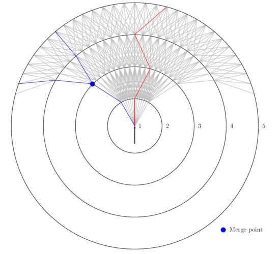
The graph G = ( V , E ) will serve as a base for finding the paths (Figure 1).

3.3. Route Modeling and Decision Variables

Based on the graph G, the result to find is a set of routes connecting the center to the exit points.
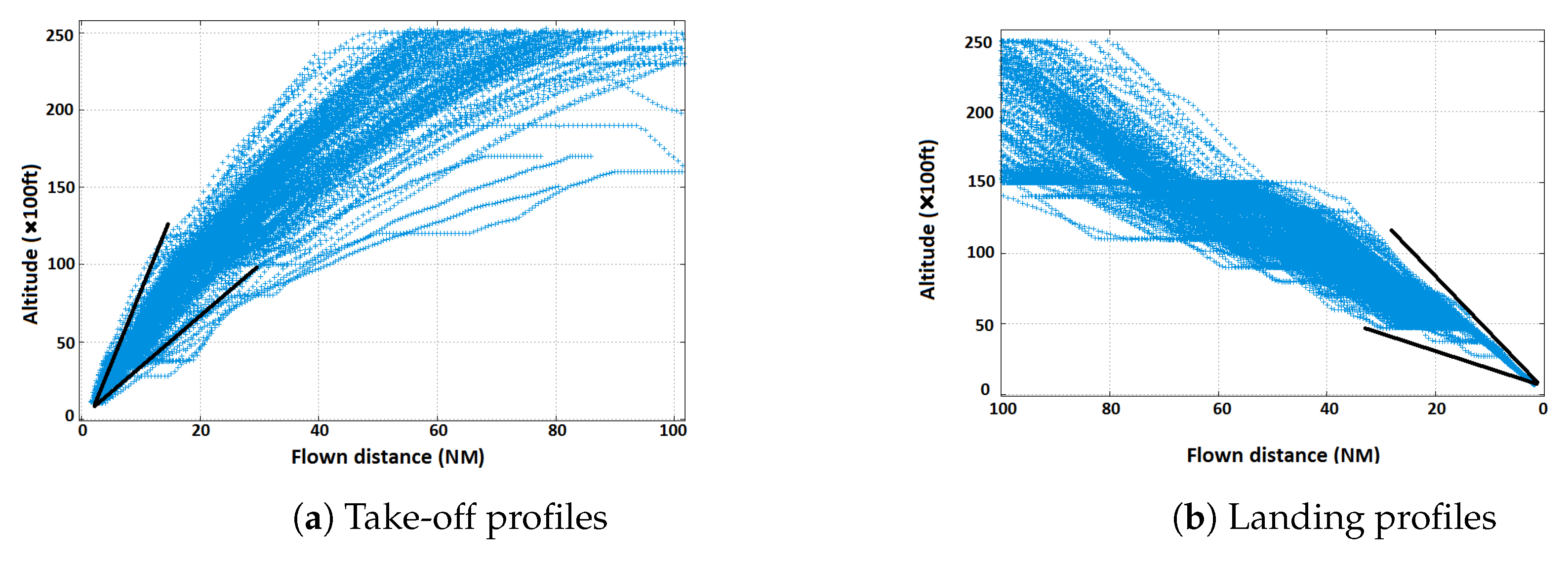
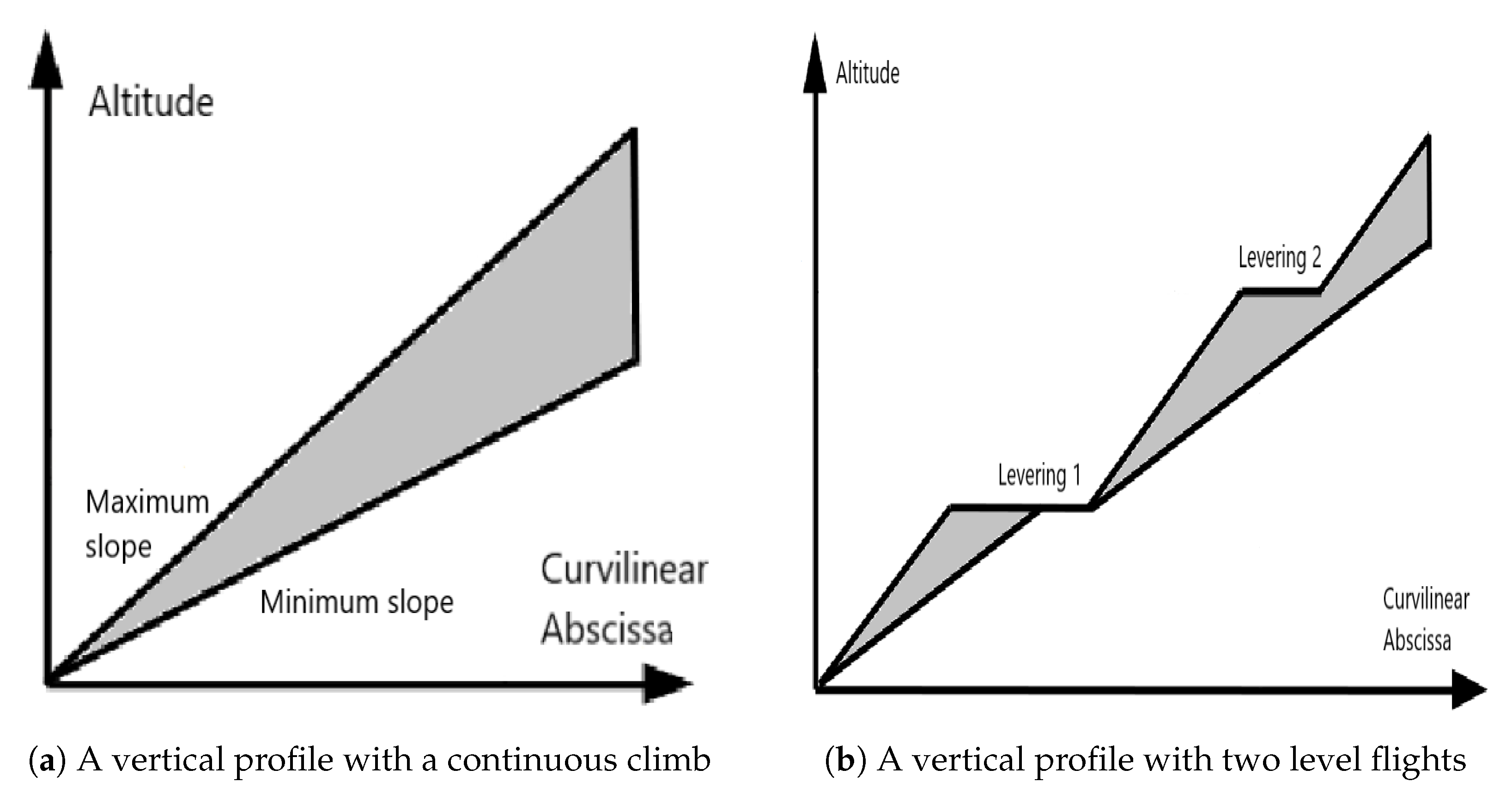
The variables of the problem are the routes to be designed. A route R for the exit P is defined as an ordered subset of E to which is added a vertical profile. The vertical profile gives the minimal and maximal possible altitudes at which an aircraft can fly at a given point along the path. This representation is motivated by the observation of the take-off and landing profiles at Charles-De-Gaulle airport (Figure 2), a large airport, representative of the ones this work aims to study. It is built taking into account the curvilinear abscissa of the path, the minimum and maximum slopes and the level flights on the path. The choice of this representation instead of 3D points has been made because the current charts represent the procedures as 2D paths with optional mentions of constrained altitudes. Thus the path and the altitude range are two distinct features of a procedure.
Basically, the decision regarding the vertical profile lies in choosing to put a level flight or not at a given arc. A route R can be defined by a couple ( γ h , γ v ) where:
( 1 ) γ h = ( e i 1 , i 2 1 , e i 2 , i 3 2 , , e i N L 1 , i N L N L 1 ) E N L 1 ( 2 ) γ v = ( z 1 , , z N L 1 ) { 0 , 1 } N L 1
The tuple γ h is called the horizontal profile of the route. The component γ v [ i ] indicates the presence (1) or absence (0) of a level flight between the layers i and i + 1 , that is, on the arc γ h [ i ] . The horizontal profile γ h can also be seen as a continuous piecewise linear function
γ h : [ 0 , 1 ] R 2
In the rest of the paper, one definition or the other will be used indifferently, as they denote the same object. Based on γ h and γ v , it is possible to give another point of view of the vertical profile according to Algorithm 1. The idea is to create two functions:
z ̲ , z ¯ : [ 0 , l ( γ h ) ] R s the minimum and maximum possible altitudes of an aircraft at flown distance s from the center
where l ( γ h ) : = 0 1 γ h ( s ) d s is the length of γ h . Later on, the curvilinear abscissa will be defined as the value d ( t ) = 0 t γ h ( s ) d s which represents the distance flown from the center to γ h ( t ) . The functions z ̲ , z ¯ are continuous piecewise linear and can be characterized by their values at curvilinear abscissa of the intersection between the route and the layers. By abuse of notation, the values corresponding to layer i are denoted by z ̲ [ i ] , z ¯ [ i ] . The vertical profile γ v will be referred to indifferently as either ( z 1 , , z N 1 ) or ( z ̲ , z ¯ ) depending on the context.
Algorithm 1 Construction of z ̲ , z ¯
Require:HorizontalPath = γ h , VerticalProfile = γ v in the binary representation, an initial altitude Altinit, a minimum slope Slopemin, a maximum slope Slopemax
  1:  Initialization: Let z ̲ = (Altinit,0,…0) and z ¯ = (Altinit,0…,0) two arrays of length N L , Alt max previous = Altinit, Alt min previous = Altinit
  2:  for i from 1 to N L 1 do
  3:   Let ( v j i , v k i + 1 ) = HorizontalPath i and Alti = VerticalProfile i
  4:   Let d = d 2 D ( v j i , v k i + 1 )
  5:   Let Altmin = Alt min previous + Slopemin d 100 and Altmax = Alt max previous + Slopemax d 100
  6:   if Alti is true then
  7:      z ̲ [ i + 1 ] min ( Alt max previous , Alt min )
  8:      z ¯ [ i + 1 ] Alt max previous
  9:      Alt min previous = min ( Alt max previous , Alt min )
10:   else
11:      z ̲ [ i + 1 ] Altmin
12:      z ¯ [ i + 1 ] Altmax
13:      Alt max previous = Alt max
14:      Alt min previous = Alt min
15:   end if
16:  end for
17:  return ( z ̲ , z ¯ )
Figure 3 gives an example of the construction of the functions z ̲ , z ¯ , in which four layers are represented (two normal climbs and two level flights in the picture on the right).
The horizontal and vertical portions of the route i that start at layer L 1 and end at layer L 2 will be denoted as γ h i [ l 1 , l 2 ] and γ v i [ l 1 , l 2 ] respectively. This allows us to define the merging layer of two routes i and j as
L i j = max l 1 , , N L l 1 , , N L γ h i [ 1 , l ] = γ h j [ 1 , l ] γ h i [ 1 , l ] = γ h j [ 1 , l ]
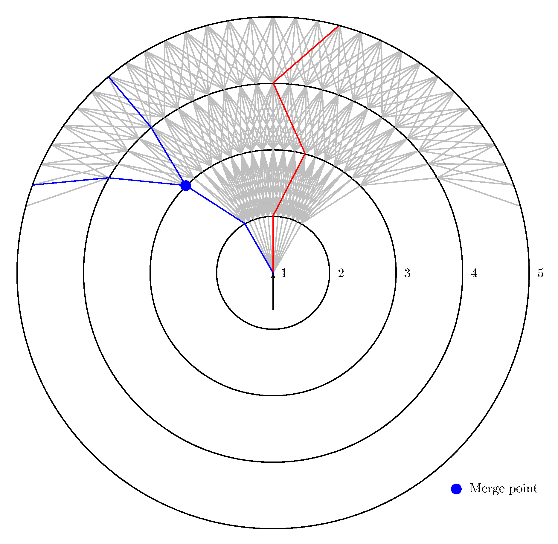
Note that, by construction, γ v i [ 1 , l i j ] = γ v j [ 1 , l i j ] . Also, l i j always exists and can be 1. In this case, the routes i and j only have the center in common. The merge point is then introduced as the common node between γ h i and γ h j located on layer L i j . For example, in Figure 4, a merge point is represented on the left, on layer 3. Finally, the family 0 = τ l 1 i < τ l 2 i < < τ l N L i = 1 is defined, such that γ h i ( [ τ l m , τ l n ] ) = γ h i [ l m , l n ] .

3.4. Constraints

The constraints stated in Section 3 are expressed in the following way:
  • Obstacle avoidance:
    o O , i 1 , , N P , t 0 , 1 , d ( γ h i ( t ) , B o ) d h or max ( z ̲ i ( d ( t ) ) , l o ) min ( z ¯ i ( d ( t ) ) , u o ) d v
    where d is the euclidean distance between two objects (i.e., the minimum distance between two points, one on the first object and the other on the second) and d h and d v are respectively the minimum horizontal and vertical distances to keep with an obstacle.
  • Route separation: The arcs of routes i and j starting on their merge point are denoted e m i and e m j . The constraint is expressed as:
    i , j 1 , , N P , j i , t τ l i j i , 1 , s τ l i j j , 1 , d ( γ h i [ l i j + 1 , N ] ( s ) γ h j [ l i j + 1 , N ] ( t ) ) d h , or max ( z ̲ i ( d ( s ) ) , z ̲ j ( d ( t ) ) ) min ( z ¯ i ( d ( s ) ) , z ¯ j ( d ( t ) ) ) d v
    and
    i , j 1 , , N P , j i , e m i e m j ^ θ min .
    This means that any two points belonging to two different routes must be horizontally separated by a minimum distance. When it is not the case, their altitudes must differ by at least a minimum vertical distance. Moreover, Equation (5) states that the angle between the two routes must be greater than a limit value at the merge point.
  • Limited turn constraint:
    n { 1 , N P } , e j , k i 1 = ( v j i 1 , v k i ) , e k , l i = ( v k i , v l i + 1 ) R n , v j i 1 v k i v l i + 1 ^ θ max
    Figure 4 illustrates this constraint: it shows (in red) a path that violates it by including too sharp turns.
  • Merge constraint:
    Two merge points that belong to a same route cannot be closer to each other than d m
  • Level flights constraint: A level flight is defined as a maximum continuous portion of route on which the maximum altitude is fixed. For example, a level flight in a SID will force the altitude to be no greater than a fixed value. The constraints on level flights are imposed in order to maximize the use of continuous climb:
    The number of level flights cannot exceed a given value n max L F The length of each level flight cannot be less than a given distance l min L F , for this wouldn t make sense in an operational context The length of each level flight cannot be greater than a given distance l max L F , to allow the aircraft to climb

3.5. Objective Function

The problem is multi-objective in nature. However, to simplify the optimization process, the objective function has been set as a weighted sum of three terms. A first goal is to create the shortest possible routes (it is assumed here that these are the fastest, even though this may not always be true). This first part of the objective is expressed:
c dist = i = 1 N P F i e γ h i l ( e )
where l ( e ) is the length of arc e. This part of the objective is called the route length criterion.
The second part of the objective is the total length of the solution sub-graph:
c graph = e E χ ( e ) l ( e )
where χ ( e ) = 1 if e belongs to at least one route, 0 otherwise. It can easily be seen that this part of the objective is different and sometimes contradictory with the previous one. This part of the objective is called the graph weight.
The last part of the objective is about cities, regarding the noise disturbance. As the air traffic and the population grow, it is more and more difficult to avoid flying over cities. However, this is also more and more required when the routes are designed. Thus, it has been taken into account as follows: the aircraft must avoid flying over them but if there is no choice, the impact has to be as small as possible, so the routes must try to pass over the least populated areas.
c noise = i = 1 N P F i τ T 0 1 z ̲ i ( d i ( t ) ) z ¯ i ( d i ( t ) ) c τ ( γ h i ( t ) , z ) dz dt
where c τ ( γ h i ( t ) , z ) is the cost of an aircraft flying at altitude z at γ h i ( t ) regarding noise emissions. The noise intensity varies with the altitude of the aircraft and its calculation can take into account many parameters [31]. As a simplification, this paper considers that the nominal noise (noise intensity besides the aircraft) is decreased by 6 dB every time the distance to the aircraft is multiplied by 2. The nominal noise at 3 meters is set here at 100 dB [32]. The cost c τ ( x , y , z ) for τ being a city is expressed as:
c τ ( x , y , z ) = η ( x , y ) · max 100 6 ln z 3 ln 2 , 0
Finally, the optimization problem is given by:
min α c dist + β c graph + γ c noise s . t . Obstacle avoidance constraint ( 3 ) Route separation constraint ( 4 ) and ( 5 ) Limited turn constraint ( 6 ) Merge constraint ( 7 ) Level flights constraint ( 8 )
where, α, β and γ are chosen by the user and express the relative importance of these criteria.
By choosing a single-objective function, all the criteria are combined into one. As a result, the solutions may be optimal in neither of these criteria, as the route length and the graph weight are contradictory objectives, most of the time (the route length objective tends to make the routes go straight from the center to the exit point while the graph weight criterion will often push the merging points towards the exits).

4. Resolution Approach

Compared to the problem modeling given in the previous section, in the resolution method some of the constraints have been relaxed to make them a part of the objective function, as it can be quite difficult to find a solution that satisfy all constraints. The aim is to manipulate a linear combination of all criteria as the objective function. The relative importance of all these criteria is for the user to choose depending on those they want to focus on. Therefore, the following constraints are affected:
  • Obstacle avoidance constraint: The obstacle avoidance becomes part of the objective: an extremely high cost is added to the route objective compared to the other criteria whenever an obstacle is traversed. This way, the priority of the algorithm is to avoid them, should it make a route longer, for example. Therefore, in certain very complex situations, the algorithm may return a solution that passes through obstacles
  • Limited turn constraint: This constraint is affected in the same way as the obstacle avoidance constraint: whenever a route contains illicit turns, it is heavily penalized in the objective.
  • Route separation: The routes are created sequentially, by decreasing the order of expected traffic flow. The aim is to prioritize the busiest routes. To handle this, all routes that have already been designed are set as obstacles regarding the design of the next ones. The airprox (routes being too close to each other) constraint then becomes similar to the obstacle constraint.

4.1. Simulated Annealing

To solve the described problem, the Simulated Annealing (SA) meta-heuristic is applied. It was first introduced in the early 1980s [22]. The aim is to make an analogy with the annealing of physical materials. The process involves bringing a solid to a sufficiently high temperature, and then let it cool down slowly in order to make it reach an optimal arrangement of its molecules. This corresponds to a state of minimum energy [33]. This method is quite efficient when it comes to optimizing a single-objective function and works in the following way:
  • Initialization: A first solution is computed, that will serve as the starting point of the algorithm. In the mean time, an initial temperature is set (see Reference [33] for the choice of this temperature)
  • Cooling loop:
    • the result of the evaluation of the objective function for the current solution is denoted y i and the current temperature of the algorithm is denoted T.
    • Creation of a neighbor for the current solution
    • Evaluation of the objective y j function for the neighbor
    • If the objective is improved, the new solution is accepted as the starting point for the next iteration. If not, it is accepted with a probability e y i y j T .
    • The temperature is decreased
  • Stopping criterion: The algorithm stops when the temperature drops below a limit value. It can also stop earlier if there is a way to know the value of the objective for the optimal solution. In this case, the SA stops if the objective attains this value.
In this section is first described how this algorithm has been adapted to the problem. The next paragraph will explain the way to build an initial solution for the starting point. Then the neighbor generation process is described and finally the way to evaluate a solution is stated.

4.2. Generating a Solution

This is the key issue to be addressed by the algorithm. The paths are created one by one, by decreasing order of traffic flow (so that the busiest path is the least constrained by the other routes). Moreover, a set of merge layers is introduced, which is a subset of L . Their purpose is to define where the merging points may be created.

4.2.1. Creating the Merge Layers

The merge layers can change during the execution of the algorithm. However, the center is always considered as a merge layer and a minimum distance between two consecutive merge layers must always be ensured. To achieve this, for instance, it can be imposed that all L i are regularly spaced by a known distance. Then, a merge layer can be set every n t h layer starting from the center. If the last merge layer is too close to the last layer L N , it must be removed so that the exit points are far enough from any merge point.

4.2.2. Finding One Path

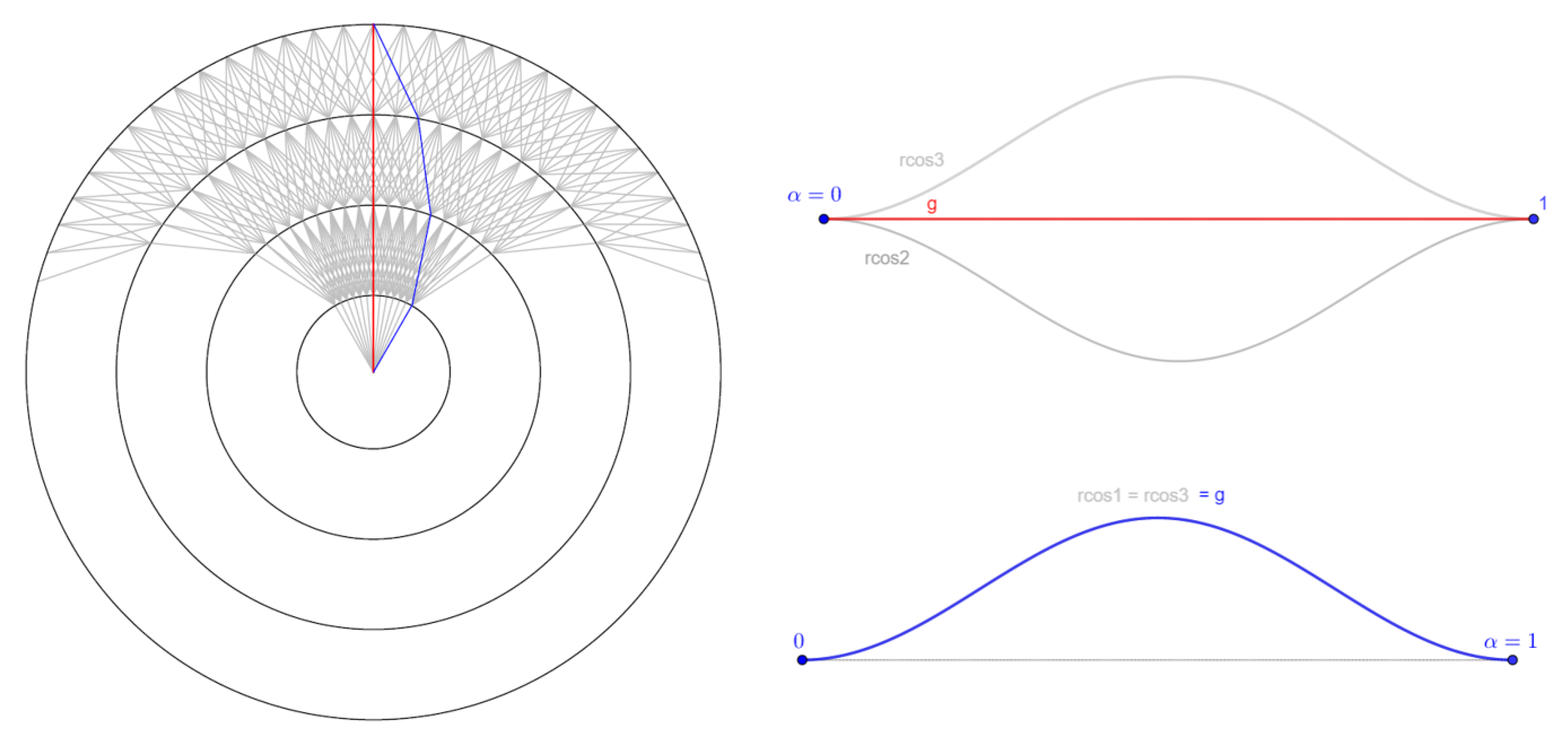
Each individual path is computed with a deterministic path search algorithm in a graph, with a carefully chosen cost for the arcs, as the algorithm has to be able to explore various possible paths for two given starting and ending points. This last point requires that the cost of the edges can vary during the execution of the algorithm. Otherwise, for two given points, the result of the search would always be the same. To achieve this, the algorithm biases the costs of the edges in the graph for each path to be computed. To each merge layer is associated a number (the bias) between −1 and +1. A negative bias will increase the costs of the arcs ’on the right’ of each node until the next merge layer, while a positive bias will increase those ’on the left’ (see Figure 5). The closer the bias is to −1 or +1, the sharper the turn will be, while a null bias will favor the straightforward paths. By resetting the costs of the arcs at each path search, it is possible to explore the entirety of the graph while keeping a way to recreate any path, given its start and end points along with the biases.
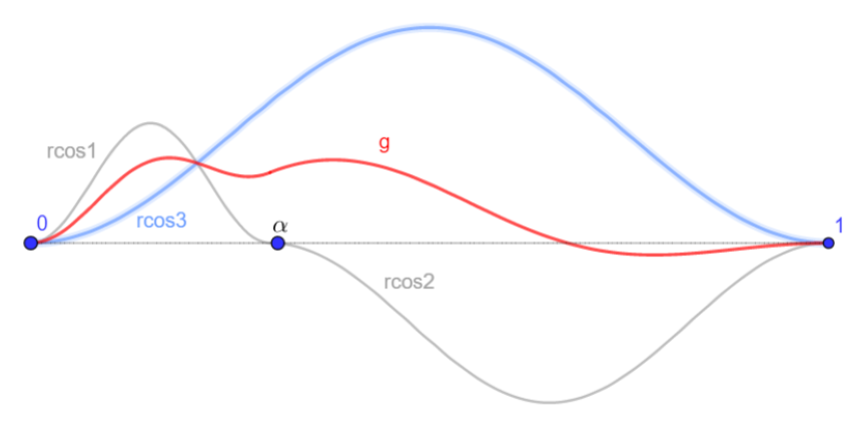
The coefficients for the cost bias are chosen in a way that helps reducing the zigzag phenomenon. The aim is to generate a sequence of numbers that are coherent with their predecessors and successors. In order to achieve this, the generation is based on the raised cosine function:
rcos ( x , μ , s ) = 1 2 s 1 + cos x μ s π on μ s , μ + s
The method works as follows, for a given starting vertex o (origin) and a given ending vertex a (arrival):
  • A number α 0 , 1 and two signs sgn 1 , sgn 2 { 1 , + 1 } are randomly chosen.
  • Three amplitude values A 1 , A 2 , A 3 in 0 , 1 are set. These values can be chosen randomly, but in this work, they are decrease down to zero with the progress of the SA. This allows to explore the state space when the temperature is high and focus on a narrower neighborhood when it is low.
  • Three raised cosine functions are generated (see Figure 6):
    • rcos 1 = sgn 1 · A 1 · α 2 · rcos ( x , α 2 , α 2 )
    • rcos 2 = sgn 1 · A 2 · 1 α 2 · rcos ( x , α + 1 α 2 , 1 α 2 )
    • rcos 3 = sgn 2 · A 3 · 1 2 · rcos ( x , 1 2 , 1 2 )
  • A function g is defined as g ( x ) = rcos 1 + rcos 2 + rcos 3 2 on 0 , 1 , by setting rcos 1 = 0 on α , 1 and rcos 2 = 0 on 0 , α
  • The coefficients are chosen so that the route to find has the same shape relatively to the segment [ o , a ] than g has relatively to [ 0 , 1 ]

4.2.3. Creating a Set of Paths

The paths are created sequentially so that the busiest routes are the least constrained. A complete set of paths is created in the way described in the Algorithm 2:
Algorithm 2 Generating a set of routes
Require: The center center, the exits P 1 , P N P ordered by decreasing traffic flow.
  1:  Initialization: Set a starting point Start = center, an null matrix Biases of size N P × ( N L 1 ) .
  2:  for i from 1 to N L 1 do
  3:   Fill Biases with the biases using the raised cosine formula. If a route begins on a layer greater than 1 or ends before the layer L , the corresponding cells of Biases are set to a default value less than 1 or greater than 1.
  4:   Set the arcs costs according to the coefficients in Biases
  5:   Set R i = Shortest path from Start to P i
  6:   Set Start = a randomly selected intersection of one of R 1 , R i with a merge layer, that is not already a merge point.
  7:  end for
  8:  return R 1 , R n
Note that the first time this function is called, all values for Biases at step 3 are set to 0. This allows to test the straightforward way, which can be the best one in some cases. The biases can start to change at the first generation of a neighbor. Thus the initial solution is created by calling Algorithm 2 and by always setting the biases (the values of the array Biases) to zero.

4.3. Generating a Neighbor

To create a neighbor, the algorithm can operate on several parameters:
  • The route of connection (see step 6 in Algorithm 2)
  • The layer on which a route connects to an other (i.e., the merge layer)
  • The coefficients for the arcs bias algorithm
  • The level flights on a route (choice of the z i )
  • The merge layers, that can be changed. In this case, all routes are computed again. This is meant to induce exploration at the beginning of the search
A neighbor is created by randomly changing one of these parameters on the current solution. Sometimes, all of them are randomly changed, to allow for more exploration. However, the probability of this happening greatly decreases with time.

4.4. Evaluation

In the simulated annealing meta-heuristic, it is necessary to be able to evaluate frequently a given solution (i.e., a set of routes). This evaluation is carried out in the same way as in Reference [12], by means of a grid with the following features:
  • The grid covers at least the area of the graph
  • Each cell of the grid is a square whose side length is not greater than the minimum horizontal separation (for example, 1 NM in this work).
  • Each cell holds the following information:
    The height of the highest ground obstacle that can be found in this cell (mountain, antenna, building…)
    The minimum and maximum altitudes of a forbidden flight zone in this area (if any)
    The density of population on the ground (if any)
Thus, the obstacles are ’widened’ due to the discretization. This allows to take additional margins, but could also lead to the loss of potential solutions. This is why it is important to keep the grid squares rather small. For the evaluation, each route is discretized with an arbitrary step, for example d h . Each of the created points belongs to one cell of the grid according to its coordinates in the plane. The evaluation of the point is carried out by considering its cell for the evaluation of obstacles or cities, and by also considering its neighboring cells (more specifically all cells in a radius of d h around the point) for the evaluation of conflicts between routes or with obstacles.

5. Simulation Results

The solution presented in this article has been implemented and tested for the design of multiple routes. The proposed methodology is first tested on STARs design taken from the literature [34] with different discretizations. Then the tests performed on artificially generated problems are presented, with various numbers of routes to design, as well as various numbers and layout of obstacles. For all of the tests, the center is the Final Approach Fix (FAF), or equivalent for the take-off. During the landing, the FAF is the point from which the aircraft go straight to the runway. They cannot turn past this point. In the same way, the center is chosen as the first point on which the aircraft can turn in the SID configuration. The tests were run on a 2.70 GHz Intel Core i7 processor with 16 GB of RAM on a Windows operating system.

5.1. The Stockholm Instance

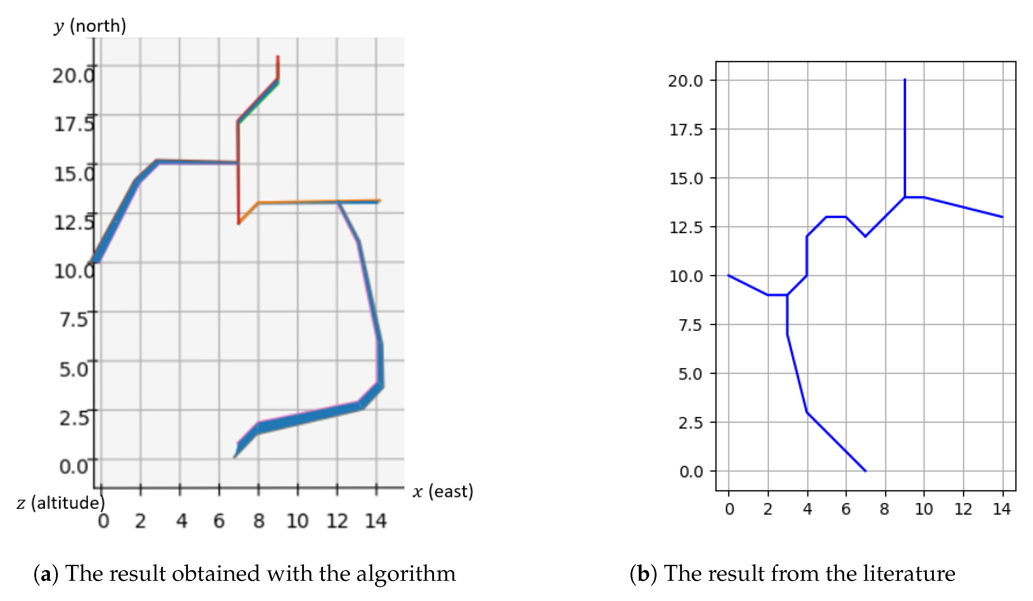
This case is based on the study presented in Reference [34] in which the problem of STAR design is addressed with an Integer Programming (IP) method to find arrival trees in the TMA in 2D. This instance was chosen as it provides a nice example to compare the performances of this work with one from the literature, with a single runway. The drawback of this approach is its execution time: 9447 s (2 h 37 min 27 s) to find the minimum weight spanning tree. The result of this approach is shown in Figure 8b. For this case, the following data were used:
  • Center = (7,12)
  • The runway is oriented by the vector ( 0 , 1 )
  • The exits are located at (14,13), (9,20), (0,10), (7,0) by decreasing order of traffic flow
  • The traffic flows are all equal
  • The altitude range of the exit points is not relevant (so all ranges are accepted in the solution)
  • Maximum turn angle θ m a x = 45 °
  • Minimum angle at merge points θ m i n = 15 °
  • The minimum and maximum slopes α m i n and α m a x are not relevant
  • The number and minimum and maximum length of the level flights n m a x L F , l m i n L F and l m a x L F are not relevant
  • The cities are considered as obstacles and are as described in Table 1
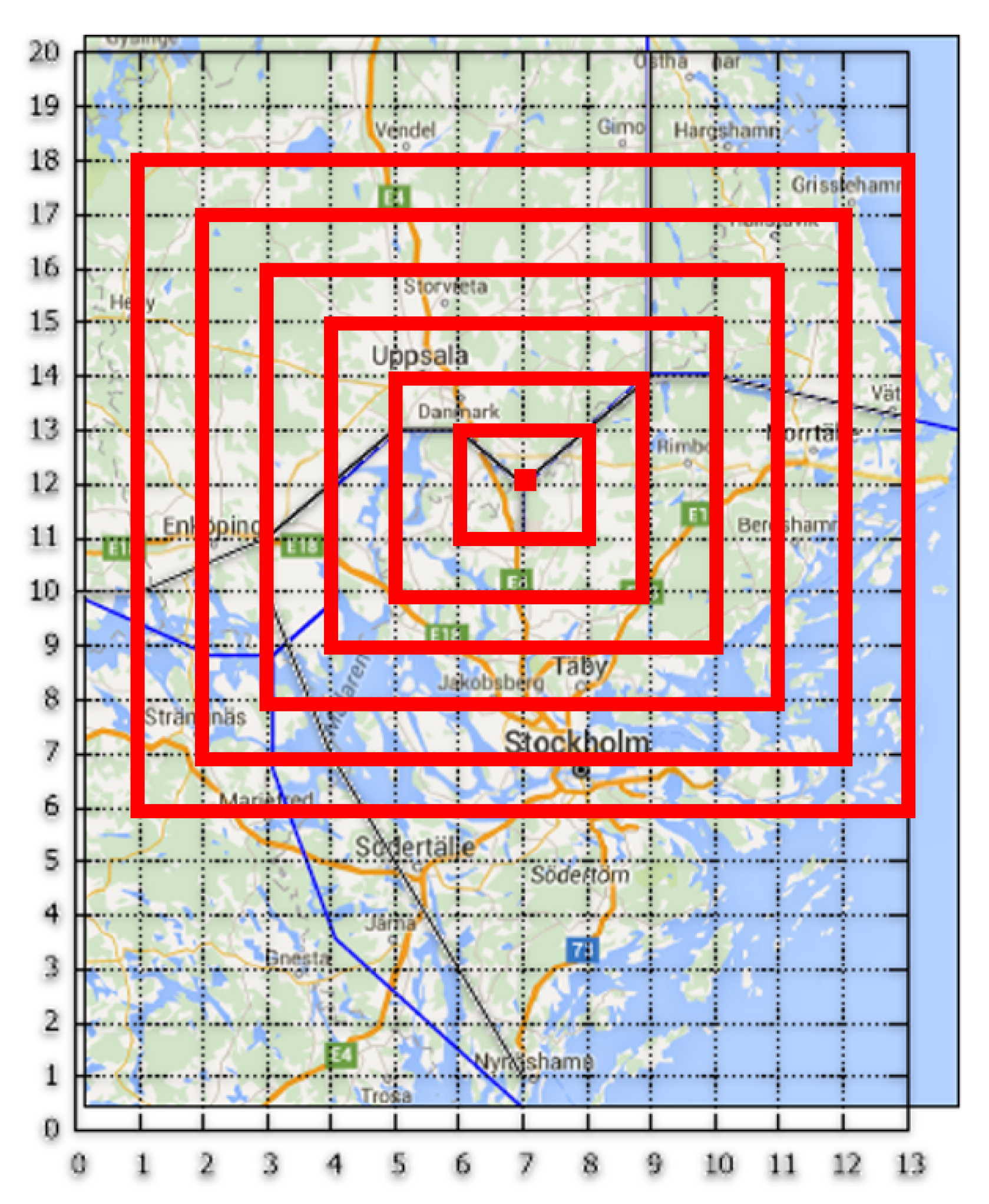
The method has been applied to two different discretizations with this configuration. In the first one, 13 concentric square layers were used. Square i has a 2 ( i 1 ) NM-long side, with square 1 being the center at (7,12). There is a vertex each 1NM on each square starting from a corner (see Figure 7). This corresponds to the grid used to formulate the IP problem in [34].
The algorithm runs in between 2.8 s and 3.2 s (the execution time has been measured on 20 runs of the algorithm), at the expanse of the exactitude of the solution. The results are shown in Figure 8.
In contrast to Reference [34], the solution is not post-processed so as to avoid the zigzag behaviors. The other point to be mentioned is that the algorithm does not allow for going from a layer L i to a layer L j with j i . This causes the route coming from the south to be longer than the IP route [34]. Overall, in this case, a decent tradeoff between solution optimality and computation time can be achieved. This allows to proceed much heavier instances so as to tackle more complex scenarios.
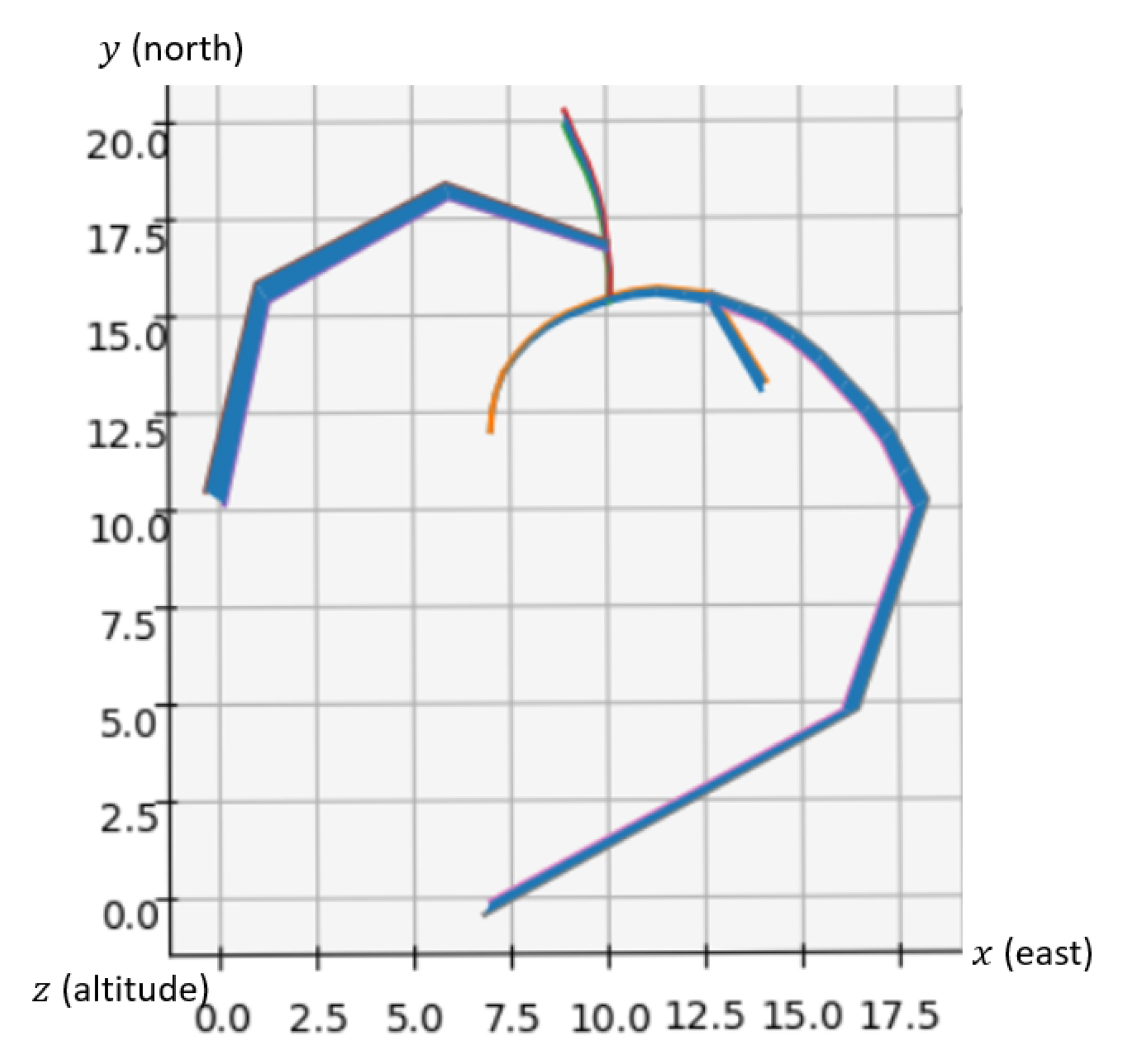
In the second discretization, the layers were 25 circles regularly spaced by 0.5 NM and uniformly discretized into 360 points each in order to see if the result is different, and if so, in what way. The result is shown in Figure 9.
The results are way less satisfactory than in the first case, as the routes are significantly longer and occupy a wider surface. Thus the choice of the layout, and more particularly the shape of the layers, has a great impact on the quality of the solution given by the algorithm.

5.2. Artificial Problem

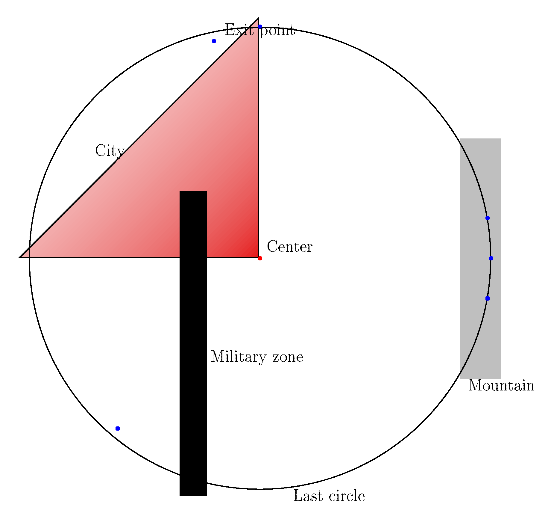
In this part, the algorithm is tested on an artificial example, first by designing one route at a time to test the effects of different types of obstacles such as a mountain, a city or a military zone, then by measuring its performances by considering all the obstacles at once with two different discretizations. The obstacles that were used are listed in Table 2.
The same construction method as in the previous case was used, with the following data:
  • Center: (0,0,0)
  • The runway is oriented by the vector ( 0 , 1 )
  • In polar coordinates, the exits are located at (346, 0°), (346, 10°), (346, 350°), (346, 90°), (328.5, 135°), (328.5, 230°) by decreasing order of traffic flow
  • The traffic flows, by decreasing order, are 26.67%, 24%, 21.33%, 13.33%, 12%, 2.67%
  • The altitude range of the exit points is not relevant (so all ranges are accepted in the solution)
  • Maximum turn angle θ m a x = 30 °
  • Minimum angle at merge points θ m i n = 15 °
  • Minimum slope α m i n : 3.24%
  • Maximum slope α m a x : 16.2%.
  • The maximum number of level flights n m a x L F = 4
  • The minimum length of the level flights was set to l m i n L F = 35 NM and the maximum length l m a x L F is not relevant here
  • The cities and obstacles are given in Table 2

5.2.1. One Route Design and One Obstacle

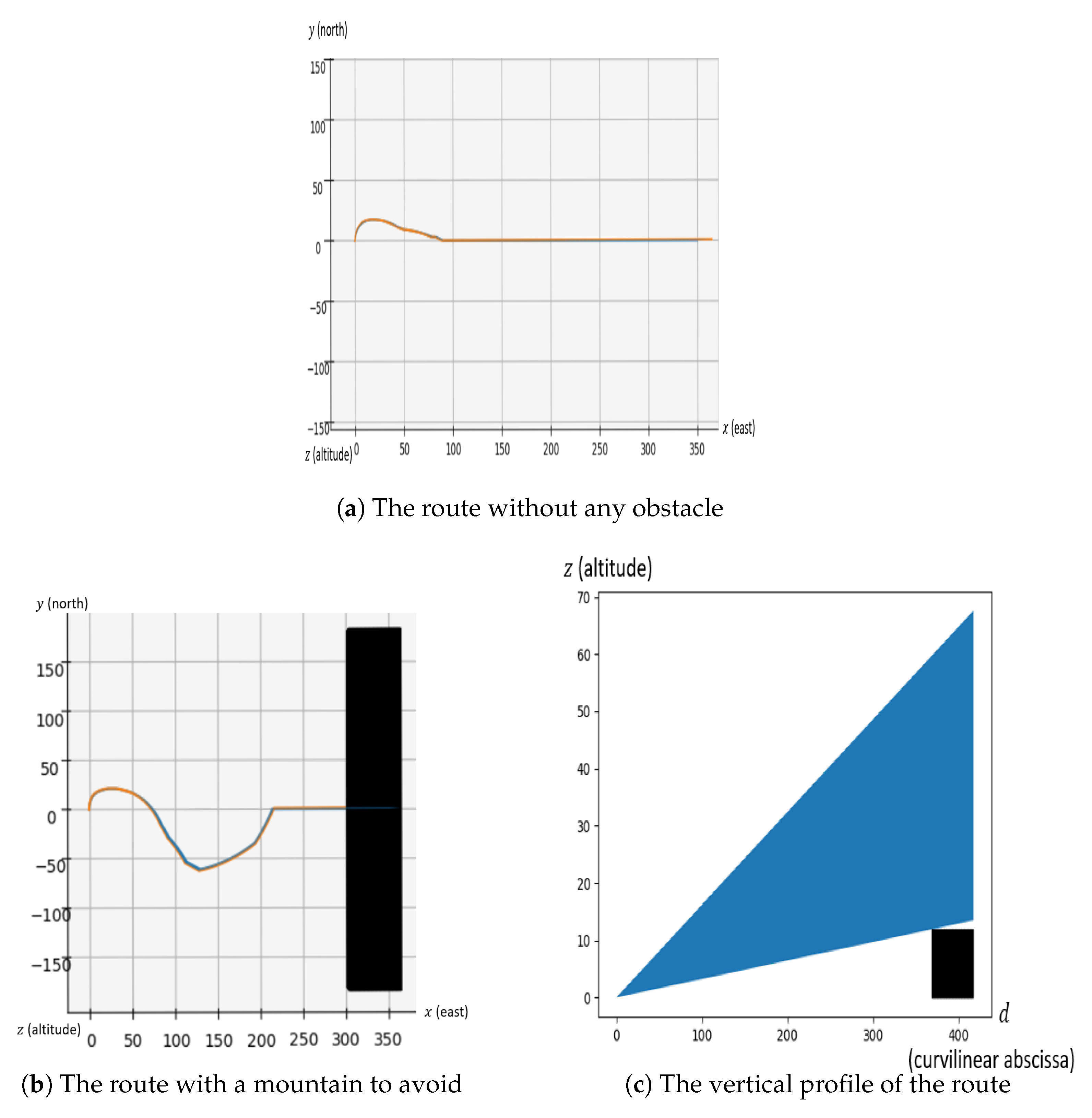
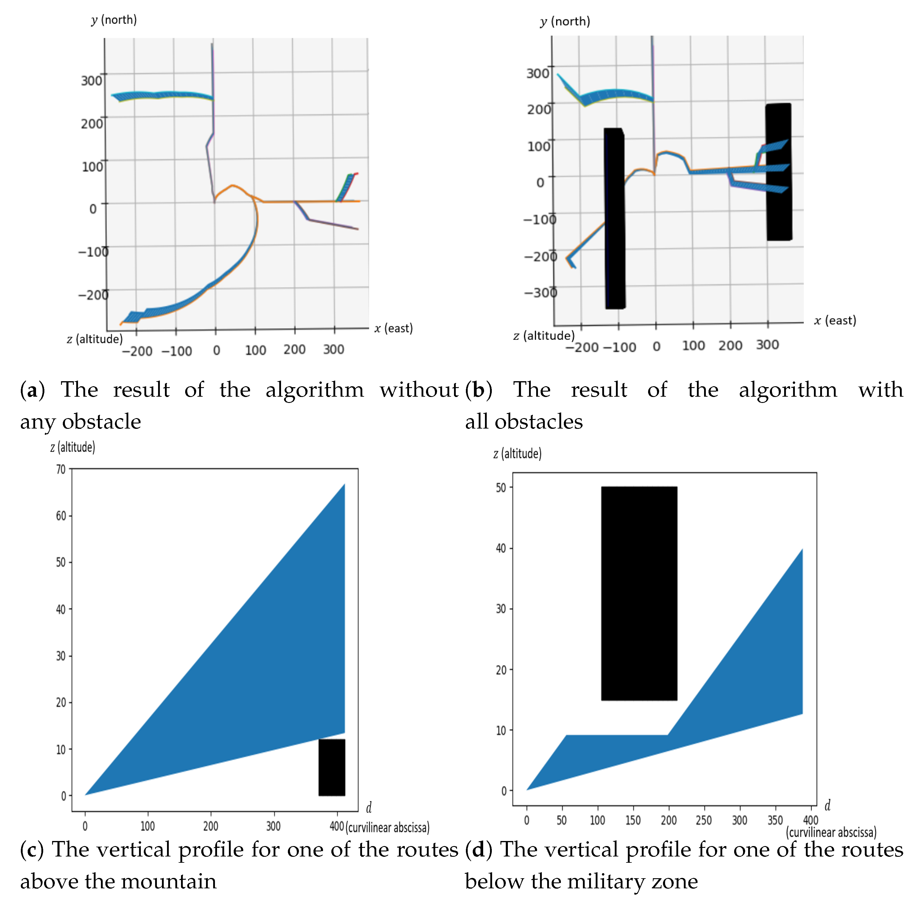
This paper successively considers the effects of a mountain, a city and a military zone on the design of one route. For each of these tests, the algorithm was first run without any obstacle, so as to set a reference. The first obstacle that has been studied is a mountain, on the right-hand side of the map (see Figure 10), too high for the route to fly in a straight line from the center to its exit point. The results are shown in Figure 11.
It can be seen from Figure 11 that the route is lengthened for the aircraft to gain altitude and to be able to fly over the obstacle.
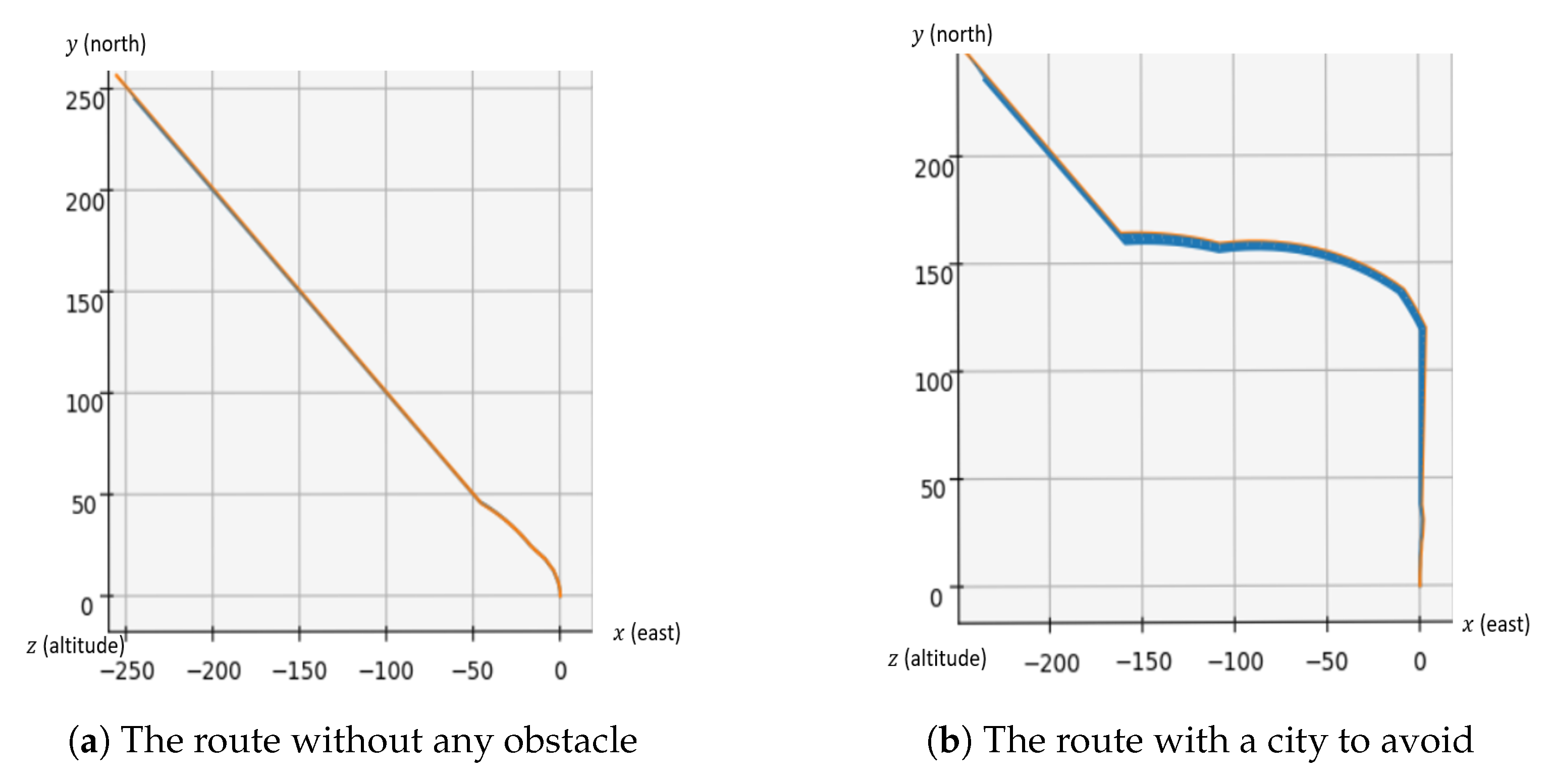
The second obstacle that has been studied is a city, as shown in Figure 10, with the highest population density at the center and decreasing towards the exterior. As before, the algorithm was first run without any constraint to set a reference. The results are shown in Figure 12.
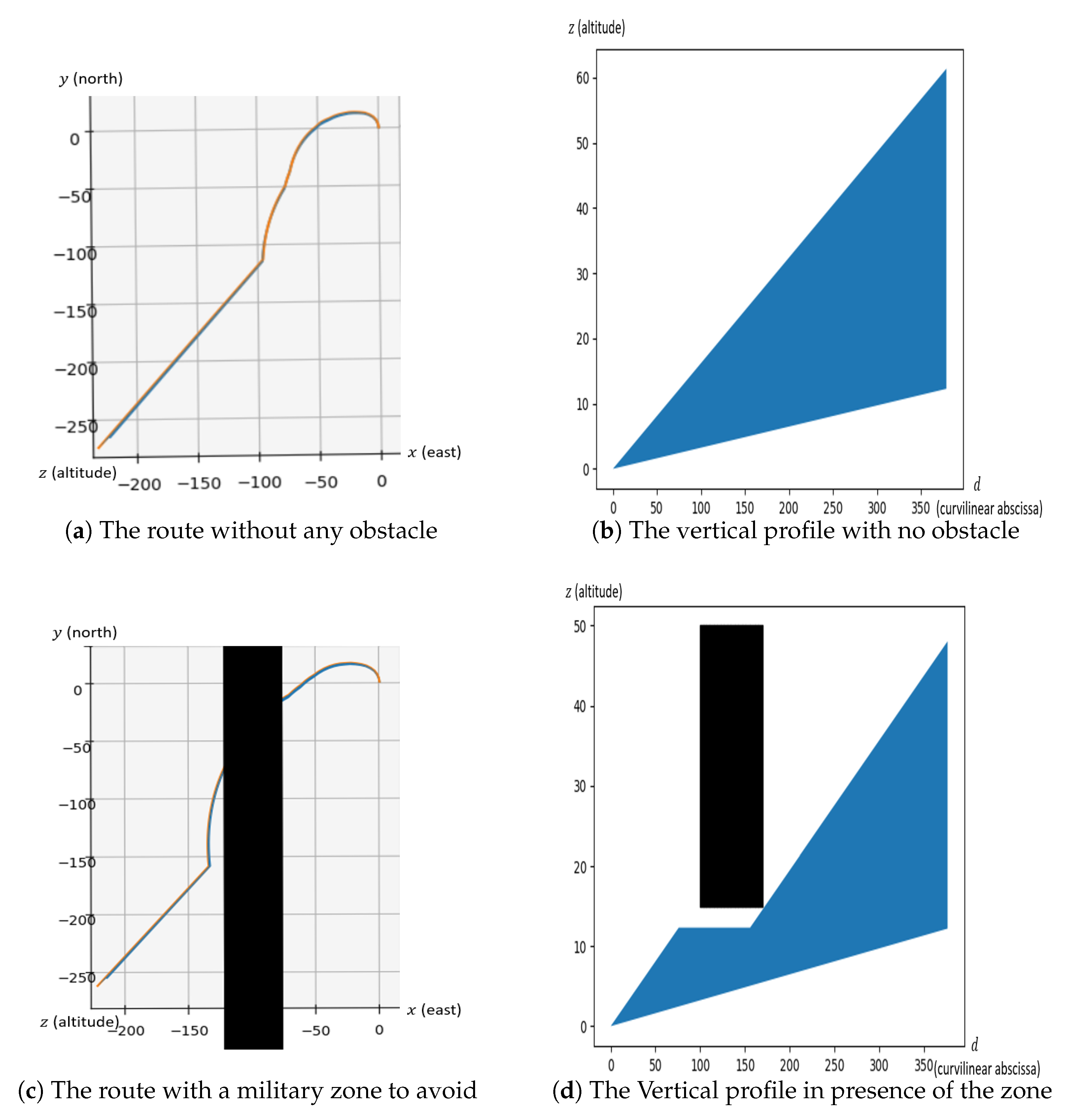
The turn towards the exit point is delayed so as to avoid flying over the most populated areas of the city and cause noise disturbance. Finally, the effects of a military zone between the center and an exit point (see Figure 10) were tested. The results are shown in Figure 13.
The algorithm does set level flights on the route for it to avoid the restricted area.
Thus, taken one by one, all the constraints are well handled by the algorithm. In the next part, the effects of all obstacles at once with several routes to be designed are studied.

5.2.2. Six Routes Design with All Obstacles

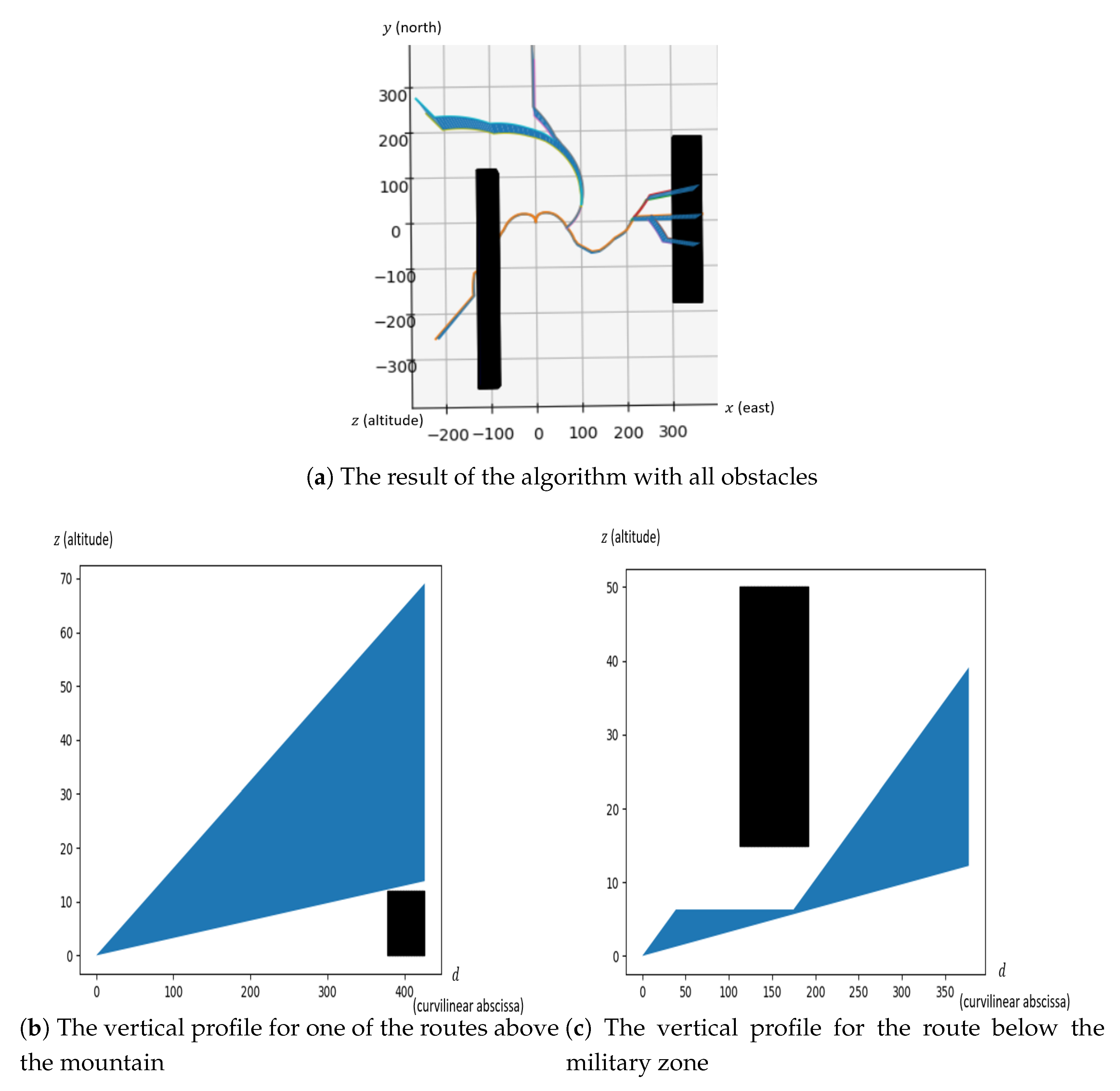
The last test has been created specifically, in order to see how the algorithm performs in a case designed to be problematic for it (Figure 10). It assumed an SID configuration with six exit points. Three of them are located quite close to each other (on the right-hand side of the image), two others at the top and a last one at the bottom. The aim is to see how the algorithm behaves when all the elements discussed in Section 5.2.1 are added. As for the other test cases, a first computation of all routes without any obstacle has been performed to set a reference. The results are shown in Figure 14.
It can be seen from Figure 14a that the routes have the expected shape—they all go in a quite straightforward way to their assigned exit points. The merges are located near the exits when several of them are close to each other, while the route on the left merges with the others quite close to the center, as no other exit is nearby. However, the routes are less straightforward than in the individual cases. This is due to the increase in the number of possible changes for a given iteration. In Figure 14b, both routes on the left have a significant change in shape. All obstacles are still avoided and the routes remain quite straightforward, making the solution quite relevant.
Finally, the same test was run but with more circles and more points per circle (see Table 3), so as to measure the performance of the algorithm in terms of computation time on large instances. This also allows us to see if it leads to a significant change in the shape of the routes. The obtained results are shown in Figure 15:
All the constraints are respected: the routes on the right fly over the mountain, and the route on the left does not pass through the military zone. However, the shape of some routes has been negatively affected compared to the previous case: both routes heading north are unnecessarily longer and their separation at the merge point is reduced. The solution is, however, still acceptable. This test makes it explicit that a heavier discretization does not necessarily improve the solution. An explanation could be that in the last case, the number of possible routes is greatly increased while the algorithm runs the same number of iterations. This causes an unnecessary exploration of similar non-viable solutions and allows for fewer improvements on the good solutions. For all tests conducted on the artificial instance, the layers have been arbitrarily chosen. Their aim is to provide a discretization both precise enough to represent the TMA, as if there are not enough, a significant part of the possible solutions can be missed, and sparse enough to keep the routes close to real ones, with a small enough number of possible turns and a minimum distance between two potential decision-making points. It also keeps the instance within the computational capabilities of the algorithm, as the computation time increases greatly with the number of points used to discretize the TMA. Note that the number of points used in a given solution does not affect the workload of the pilots, as procedures are integrated once into the MCDU and pilots only have to select the entire procedure to follow, not every waypoint. Table 3 gives some indicators on the performed tests.
In a nutshell, it can be concluded that the angular stone of the method lies in the choice of the discretization: shape and number of the layers, number and points per layer. Although it has not been explicitly tested, it can also be inferred that the distribution of the points on the layers plays an important role. An idea would be to increase their number in the vicinity of obstacles and allow fewer of them in open areas.

6. Conclusions

In this paper, a method for the design of multiple SIDs and STARs at a strategic level has been proposed. The objective is to obtain a set of 3D routes that provides a balance between individual route shortness and overall graph length. The proposed approach takes into account the presence of obstacles, cities, the need to progressively merge the routes and the route separation constraints. The routes are modeled as successions of arcs in a 2D graph to which are associated cones of altitudes to represent the vertical profile.
The problem is modeled as a combinatorial optimization problem that is addressed with the Simulated Annealing algorithm. The method has been tested on an example taken in the literature as well as on an artificial scenario. The results are satisfactory in regard of the current state of Air Traffic Management, especially for the controllers’ workload. The tests that were performed, however, show that the operational relevance of the solutions given by the algorithm as well as the computation time performance decrease with the increase in number of layers and discretization points. Depending on the parameters chosen for the optimization process (relative importance of the graph weight, route length and noise disturbance) as well as the number and shape of the layers, the solutions can vary greatly. There is no generic way of constructing the layers, but as a guideline, it is suggested to space them by at least the minimum distance to keep between aircraft and obstacles and by no more than 20% of the distance in a straight line between the center and the nearest exit of the TMA. An increased density of points around obstacles should help finding better routes, while a heavy discretization is not necessary in “empty” areas. Altogether, the approach proposed in this paper is expected to provide satisfactory results in a real-life scenario, even though it must be viewed as a decision-making tool rather than an autonomous procedure design program. The natural continuation of this work is to extend it to the case of multiple runways and airports in the same TMA. It would also be interesting to run a multi-objecive algorithm to obtain a Pareto front rather than a single solution to the problem.

Author Contributions

Conceptualization, J.C. and D.D.; methodology, J.C., D.D. and M.S.; software, J.C. and D.D.; validation, J.C. and D.D.; formal analysis, J.C., M.S. and P.M.; writing—original draft preparation, J.C., M.S. and P.M.; writing—review and editing, J.C., M.S. and P.M.; visualization, J.C., M.S. and P.M.; supervision, M.S., D.D. and P.M.; funding acquisition, D.D. and M.S.

Funding

This work is partially supported by the Région Occitanie.

Conflicts of Interest

The authors declare no conflict of interest.

Nomenclature

P 1 , P N P the entry or exit points of the TMA
F i the expected traffic flow on the entry/exit point P i
R i an air route connecting P i to the runway
γ h i the projection of route R i on the horizontal plan
γ v i the vertical profile of route R i
z ̲ i ( s ) , z ¯ i ( s ) the minimal and maximal altitudes that an aircraft can attain at distance s from the starting point of route R i
O the set of all obstacles
o = ( B o , l o , u o ) O an obstacle given by its base polygon B o , lower and higher altitudes (resp. l o and u o )
Tthe set of all cities
τ = ( B τ , η τ ) T a city given by its location in the plane as a polygon B τ , and the density function η τ : B τ R + that gives the population density at a given point in the city
α min and α max the minimum and maximum climb slopes
d h and d v respectively the minimum horizontal and vertical distances to keep with an obstacle
d m the minimum distance to keep between two merge points
θ min the minimum angle between two routes at a merge point
θ max the maximum authorized turn angle
n max L F the maximum number of level flights
l min L F , l max L F the minimum and maximum length of a level flight

References

  1. ICAO. Required Navigation Performance Authorization Required (RNP AR) Procedure Design Manual; ICAO: Montreal, QC, Canada, 2009. [Google Scholar]
  2. ICAO. Continuous Climb Operations (CCO) Manual; ICAO: Montreal, QC, Canada, 2010. [Google Scholar]
  3. ICAO. Continuous Descent Operations (CDO) Manual; ICAO: Montreal, QC, Canada, 2010. [Google Scholar]
  4. Dijkstra, E.W. A Note on Two Problems in Connexion with Graphs. Numer. Math. 1959, 1, 269–271. [Google Scholar] [CrossRef]
  5. Bellman, R. On a Routing Problem. Q. Appl. Math. 1958, 16, 87–90. [Google Scholar] [CrossRef]
  6. LaValle, S.M. Planning Algorithms; Cambridge University Press: Cambridge, UK, 2006. [Google Scholar]
  7. Delahaye, D.; Puechmorel, S.; Tsiotras, P.; Feron, E. Mathematical Models for Aircraft Trajectory Design: A Survey. In Air Traffic Management and Systems: Selected Papers of the 3rd ENRI International Workshop on ATM/CNS (EIWAC2013); Springer: Tokyo, Japan, 2014; pp. 205–247. [Google Scholar] [Green Version]
  8. Lozano-Pérez, T.; Wesley, M.A. An algorithm for Planning Collision-Free Paths Among Polyhedral Obstacles. Commun. ACM 1979, 22, 560–570. [Google Scholar] [CrossRef]
  9. Liu, Y.H.; Arimoto, S. Path Planning Using a Tangent Graph for Mobile Robots among Polygonal and Curved Obstacles. Int. J. Robot. Res. 1992, 11, 376–382. [Google Scholar] [CrossRef]
  10. Kim, D.; Yu, K.; Cho, Y.; Kim, D.; Yap, C. Shortest Paths for Disc Obstacles. In Proceedings of the International Conference on Computational Science and Its Applications (ICCSA 2004), Assisi, Italy, 14–17 May 2004; Springer: Berlin/Heidelberg, Germany, 2004; pp. 62–70. [Google Scholar]
  11. Pierre, S.; Delahaye, D.; Cafieri, S. Aircraft Trajectory Planning with Dynamical Obstacles by Artificial Evolution and Convex Hull Generations. In Proceedings of the 2015 ENRI International Workshop on ATM/CNS (EIWAC2015), Tokyo, Japan, 17–19 November 2015. [Google Scholar]
  12. Zhou, J. Optimal Design of SIDs/STARs in Terminal Maneuvering Area. Ph.D. Thesis, Université Toulouse 3 Paul Sabatier, Toulouse, France, 2017. [Google Scholar]
  13. Bygi, M.N.; Ghodsi, M. 3D Visibility Graph. In Proceedings of the Computational Science and its Applications, Kuala Lumpur, Malaysia, 26–29 August 2007. [Google Scholar]
  14. Gianazza, D.; Durand, N.; Archambault, N. Allocating 3D-trajectories to air traffic flows using A* and genetic algorithms. In Proceedings of the International Conference on Computational Intelligence for Modelling, Control and Automation (CIMCA 2004), Queensland, Australia, 12–14 July 2004. [Google Scholar]
  15. Zhou, J.; Cafieri, S.; Delahaye, D.; Sbihi, M. Optimizing the Design of a Route in Terminal Maneuvering Area Using Branch and Bound. In Proceedings of the 2015 ENRI International Workshop on ATM/CNS (EIWAC2015), Tokyo, Japan, 17–19 November 2015. [Google Scholar]
  16. Pfeil, D.M. Optimization of Airport Terminal-Area Air Traffic Operations under Uncertain Weather Conditions. Ph.D. Thesis, Massachusetts Institute of Technology, Cambridge, MA, USA, 2011. [Google Scholar]
  17. Polishchuk, V. Generating Arrival Routes with Radius-to-Fix Functionalities. In Proceedings of the 7th International Conference on Research in Air Transportation (ICRAT 2016), Philadelphia, PA, USA, 20–24 June 2016. [Google Scholar]
  18. Zhou, J.; Cafieri, S.; Delahaye, D.; Sbihi, M. Optimization of Arrival and Departure Routes in Terminal Maneuvering Area. In Proceedings of the 6th International Conference on Research in Air Transportation (ICRAT 2014), Istanbul, Turkey, 26–30 May 2014. [Google Scholar]
  19. Lawler, E.L.; Wood, D. Branch-and-Bound Methods: A Survey. Oper. Res. 1966, 16, 699–719. [Google Scholar] [CrossRef]
  20. Hart, P.; Nilsson, N.; Raphael, B. A Formal Basis for the Heuristic Determination of Minimum Cost Paths. IEEE Trans. Syst. Sci. Cybern. 1968, 4, 100–107. [Google Scholar] [CrossRef]
  21. Ferguson, D.; Likhachev, M.; Stentz, A. A Guide to Heuristic-based Path Planning. In Proceedings of the International Workshop on Planning under Uncertainty for Autonomous Systems, International Conference on Automated Planning and Scheduling (ICAPS), Monterey, CA, USA, 5–10 June 2005. [Google Scholar]
  22. Kirkpatrick, S.; Gelatt, C.D.; Vecchi, M.P. Optimization by simulated annealing. Science 1983, 220, 671–680. [Google Scholar] [CrossRef]
  23. Holland, J.H. Adaptation in Natural and Artificial Systems, 1st ed.; University of Michigan Press: Ann Arbor, MI, USA, 1975; reprinted by MIT Press: Cambridge, MA, USA, 1992. [Google Scholar]
  24. Dreo, J.; Petrowski, P.; Siarry, P.; Taillard, E. Metaheuristics for Hard Optimization; Springer: Berlin/Heidelberg, Germany, 2005. [Google Scholar]
  25. Eurocontrol. Guidance Material for the Design of Terminal Procedures for Area Navigation (DME/DME, B-GNSS, Baro-VNAV and RNP-RNAV); Eurocontrol: Brussels, Belgium, 2003. [Google Scholar]
  26. Eurocontrol. Guidance Material for the Design of Terminal Procedures for DME/DME and GNSS Area Navigation; Eurocontrol: Brussels, Belgium, 1999. [Google Scholar]
  27. Skybrary. Aircraft Performances. Available online: https://www.skybrary.aero/index.php/Category:Manufacturer (accessed on 25 January 2019).
  28. Guys, L. Planification de Trajectoires d’Avions sans Conflit: Fonctions Biharmoniques et Fonction de Navigation Harmonique. Ph.D. Thesis, Universite Toulouse 3 Paul Sabatier, Toulouse, France, 2014. [Google Scholar]
  29. Dougui, N.E. Planification de Trajectoires Avion: Approche par Analogie Lumineuse. Ph.D. Thesis, Universite Toulouse 3 Paul Sabatier, Toulouse, France, 2011. [Google Scholar]
  30. ICAO. Aircraft Operations (PANS-OPS); ICAO: Montreal, QC, Canada, 2014. [Google Scholar]
  31. Schäffer, B.; Zellmann, C.; Pluess, S.; Eggenschwiler, K.; Bütikofer, R.; Wunderli, J. Sound source data for aircraft noise calculations—State of the art and future challenges. In Proceedings of the EURONOISE 2012, Prague, Czech Republic, 10–13 June 2012. [Google Scholar]
  32. Federal Aviation Administration. Aircraft Noise Levels. Available online: https://www.faa.gov/about/office_org/headquarters_offices/apl/noise_emissions/aircraft_noise_levels/ (accessed on 13 April 2019).
  33. Delahaye, D.; Chaimatanan, S.; Mongeau, M. Simulated Annealing: From Basics to Applications; Springer: Cham, Switzerland, 2018; pp. 1–35. [Google Scholar]
  34. Granberg, T.A.; Polishchuk, T.; Polishchuk, V.; Schmidt, C. Automatic Design of Aircraft Arrival Routes with Limited Turning Angle. In Proceedings of the 16th Workshop on Algorithmic Approaches for Transportation Modelling, Optimization, and Systems (ATMOS16), Aarhus, Denmark, 25 August 2016. [Google Scholar]
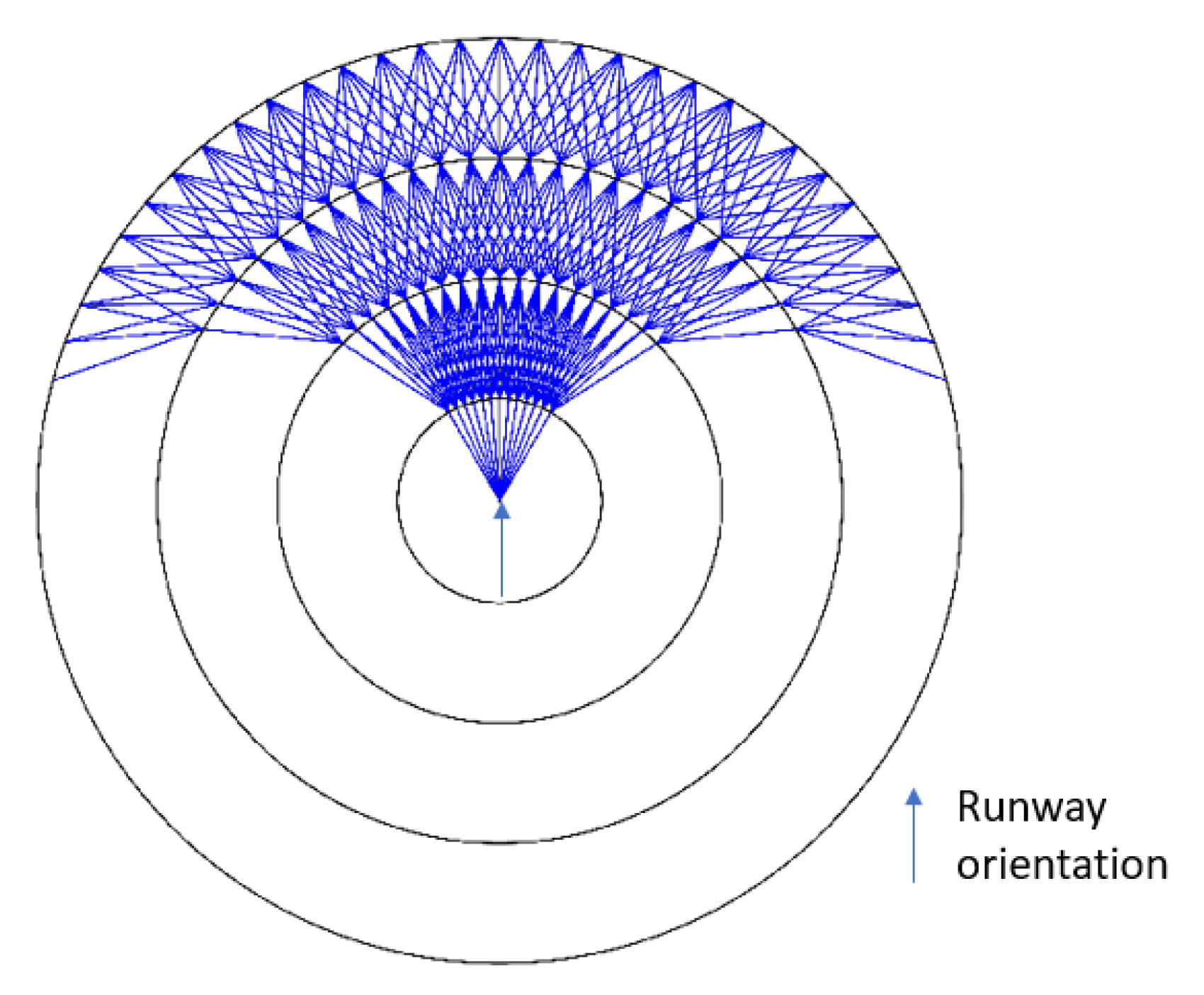
Figure 1. An example of discretization and graph construction (Five layers, one vertex every 5°, θ m a x = 30°).
Aerospace 06 00080 g001
Figure 2. Take-off and landing profiles in Paris CDG airport [12].
Aerospace 06 00080 g002
Figure 3. Illustration of the vertical profile z γ .
Aerospace 06 00080 g003
Figure 4. A forbidden path with θ m a x = 30 ° (in red) and the illustration of a merge point (in blue).
Aerospace 06 00080 g004
Figure 5. Two paths to the same exit and the associated biais functions.
Aerospace 06 00080 g005
Figure 6. The raised cosine functions to determine the biases in a general case.
Aerospace 06 00080 g006
Figure 7. The configuration for the Stockholm instance with 7 of the 13 layers.
Aerospace 06 00080 g007
Figure 8. The Stockholm instance.
Aerospace 06 00080 g008
Figure 9. The result of the algorithm on the Stockholm instance by using circular layers.
Aerospace 06 00080 g009
Figure 10. The layout used to test the algorithm.
Aerospace 06 00080 g010
Figure 11. The effects of a mountain on the route design.
Aerospace 06 00080 g011
Figure 12. The effects of a city on the route design.
Aerospace 06 00080 g012
Figure 13. The effects of a military zone on the route design.
Aerospace 06 00080 g013
Figure 14. The result of the algorithm with all obstacles at once.
Aerospace 06 00080 g014
Figure 15. The result with all obstacles with a heavier discretization.
Aerospace 06 00080 g015
Table 1. The obstacles for test 1.
Obstacle ( B ,   l ,   u )
Enköping(((1,10);(3,10);(3,12);(1,12)), 0, + )
Stockholm(((7,6);(9,6);(9,8);(7,8)), 0, + )
Uppsala(((5,13);(6,13);(6,15);(5,15)), 0, + )
Sodertäle(((5,4);(5,5);(6,5);(6,4)), 0, + )
Table 2. The obstacles and city for test 2 (see Figure 10).
Obstacle NumberObstacle Type ( B ,   l ,   u ) or ( B ,   η )
1Mountain(((300,−180); (300,178); (359,178); (359,−180)), 0, 12)
2City(((−2,1); (−360,1); (−2359)), ( x , y ) 806 ( y x ) )
3Military Area(((−120,−355); (−80,−355); (−80,100); (−80,−355)), 15, 50)
Table 3. The numerical results of the experiments.
Test Case(# of Layers, # of Points per Layer)Computation TimeObstacles (Table Number) Routes Length with Obstacles Graph Weight with Obstacles
Routes Length without Obstacles Graph Weight without Obstacles
Stockholm(13,*)2.67 sAll (1) 51.81 43.39
** **
(25,360)1 min 48 sAll (1) 71.47 52.90
** **
Single route(50,72)9 min 20 s1 (2) 417.36 417.36
358.61 358.61
(50,72)8 min 53 s2 (2) 394.50 394.50
344.79 344.79
(50,72)9 min 0 s3 (2) 376.17 376.17
378.83 378.83
Six routes(50,72)4 min 08 s1,2,3 (2) 2970.13 1874.41
2701.98 1673.86
(100,360)19 min 38 s1,2,3 (2) 2928.00 2096.64
2568.06 1601.70
** Tests without obstacles have not been conducted, as the example chosen from the literature took cities into account. For the Single route tests and the first of the Six routes cases, the first circle has a radius of 6.5 NM and the subsequent circles each have a radius 7 NM longer than the previous one. For Test case 3.2, the first circle has a radius of 3 NM and the subsequent circles each have a radius 3.5 NM longer than the previous one. All run times, as well as costs for the Six routes test are always computed as the mean value over at least 10 runs of the algorithm. All distances and altitudes are measured in NM. The layers are concentric circles when not stated otherwise. The discretization points are always uniformly distributed on each layer.