Departure and Arrival Routes Optimization Near Large Airports
Abstract
1. Introduction
2. Problem Statement
- Obstacle avoidance: The most important requirement. Aircraft must be sufficiently far from any obstacle at all times. How to ensure such protection is a vast and complex topic and depends (among other things) on the type of procedure that is designed ([1,25,26]). Based on the type of instruments used to navigate, the margins can vary in wideness. Therefore, an RNP procedure will allow for lesser space between the route and the obstacles than a standard procedure, since the precision of the equipments is sharper. However, all aircraft may be equipped with various instruments and the procedure designers must create the routes accordingly.
- Noise abatement: Quite related to the previous constraint, this one depends mainly on the size of the city under consideration. Usually, designers try to create the routes in such a way that aircraft will not fly over it (as much as possible), for noise abatement purposes. Sometimes, flying over a city is totally prohibited and the problem is taken back to an obstacle avoidance constraint. In the rest of the paper, the towns will be denoted , the set of cities over which an aircraft may fly when there is no other possibility.
- Route separation: In order to avoid aircraft coming too close to each other when flying different routes (airprox) (generally 3 NM when they are in the same horizontal plane), these routes must be sufficiently far from each other. When the horizontal separation between routes is not possible, they have to be spaced by a minimum vertical separation (usually 1000 ft). This may require the use of level flights, yet it is preferable to use as few as possible. The exception to this constraint is whenever two routes merge into one. In that case, the separation is impossible. These areas require much attention from the controllers due to the risks of airprox.
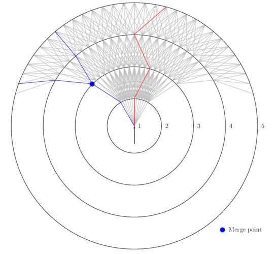
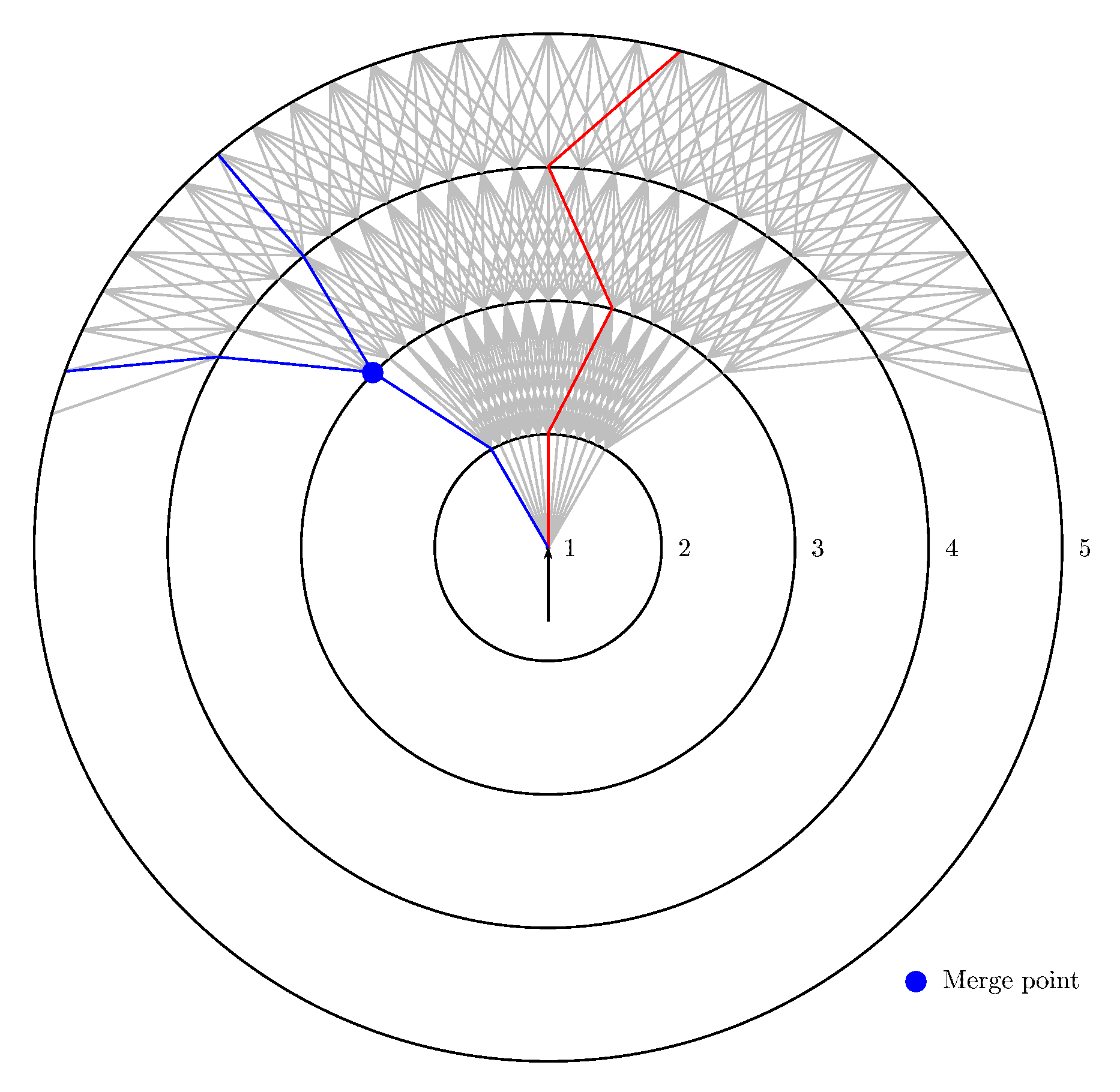
- Merging points separation: In the case of STARs, all aircraft have to converge on a single route in order to land. It is inconceivable to merge all routes on the same spot, as the workload would be far too high for the controllers. Instead, the routes must merge progressively with one another, only two at a time (three in some particular cases). These merge points will be where most conflicts could occur and thus where the controllers will put their focus. Therefore, two merge points cannot be too close to each other, or too close to the entries/exits of the TMA, to let them the time to anticipate.
- Route flyability: Aircraft have certain structural limitations that do not allow them to climb too fast or make a turn too sharp, for example. Each has a preferred and maximum possible bank angle and rate of climb given by the constructor. These limits cannot be exceeded, so the SIDs and STARs design must take these limitations into account to ensure that the aircraft will be able to fly the routes. More information on aircraft operational characteristics can be found in Reference [27].
3. Problem Modelling
3.1. Input Data
- Location and orientation of each runway taken into account in the TMA
- All obstacles in the TMA (mountains, buildings, military zones…) denoted by the set . The way of protecting the routes from obstacles will not be discussed here. Therefore, it will be assumed that all obstacles given comprise a satisfactory margin of protection. More information on how to build protection areas around procedures can be found in Reference [30]. An obstacle is viewed as a cylinder: a 2D polygon , given as a list of points, forms the base, and a minimum and a maximum altitude, and , that give the lower and upper limits of the obstacle. Later on, an obstacle will be denoted as for its base, lower and upper limits
- The set of cities T as 2D polygons on the ground with their population distribution that gives the population density at a given point in the city. The cost of flying over a city is denoted as
- The entry and exit points of the TMA . These are 2D points associated to an altitude range. This range represents the minimum and maximum altitudes at which the aircraft can go through the point.
- The expected traffic flow at each of these points
- A maximum turn angle , as aircraft limitations and regulations prevent them from making too sharp turns.
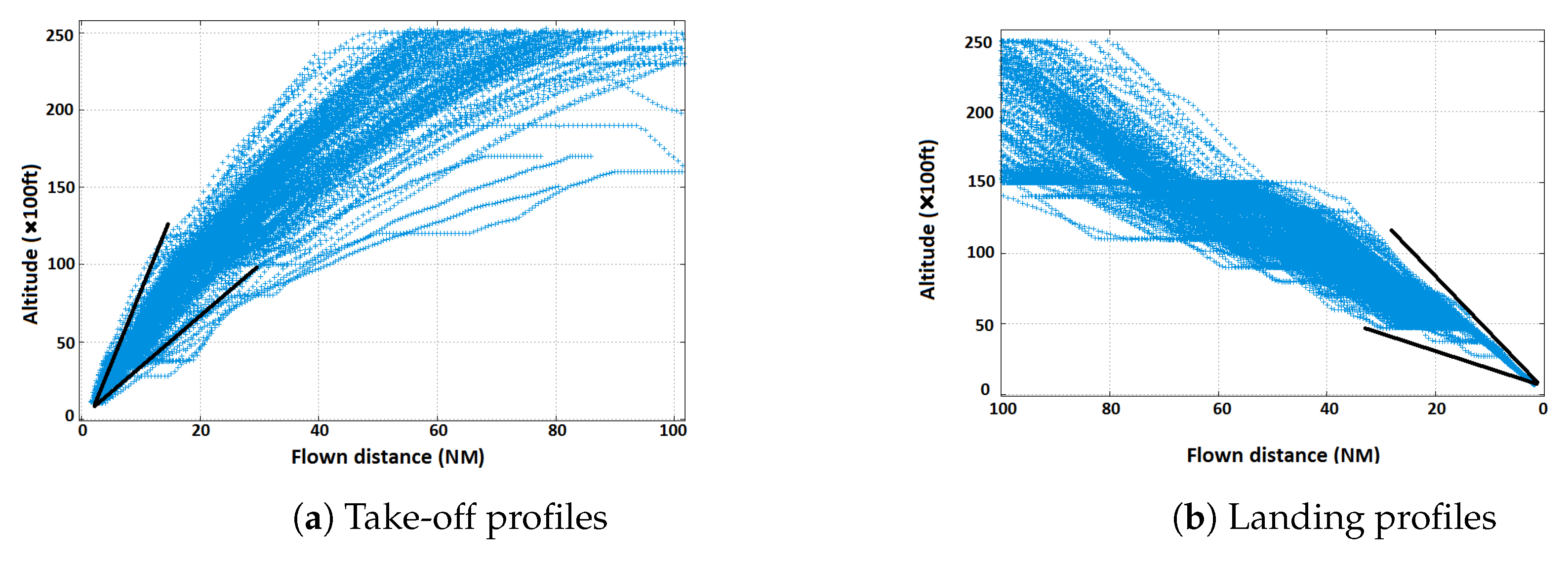
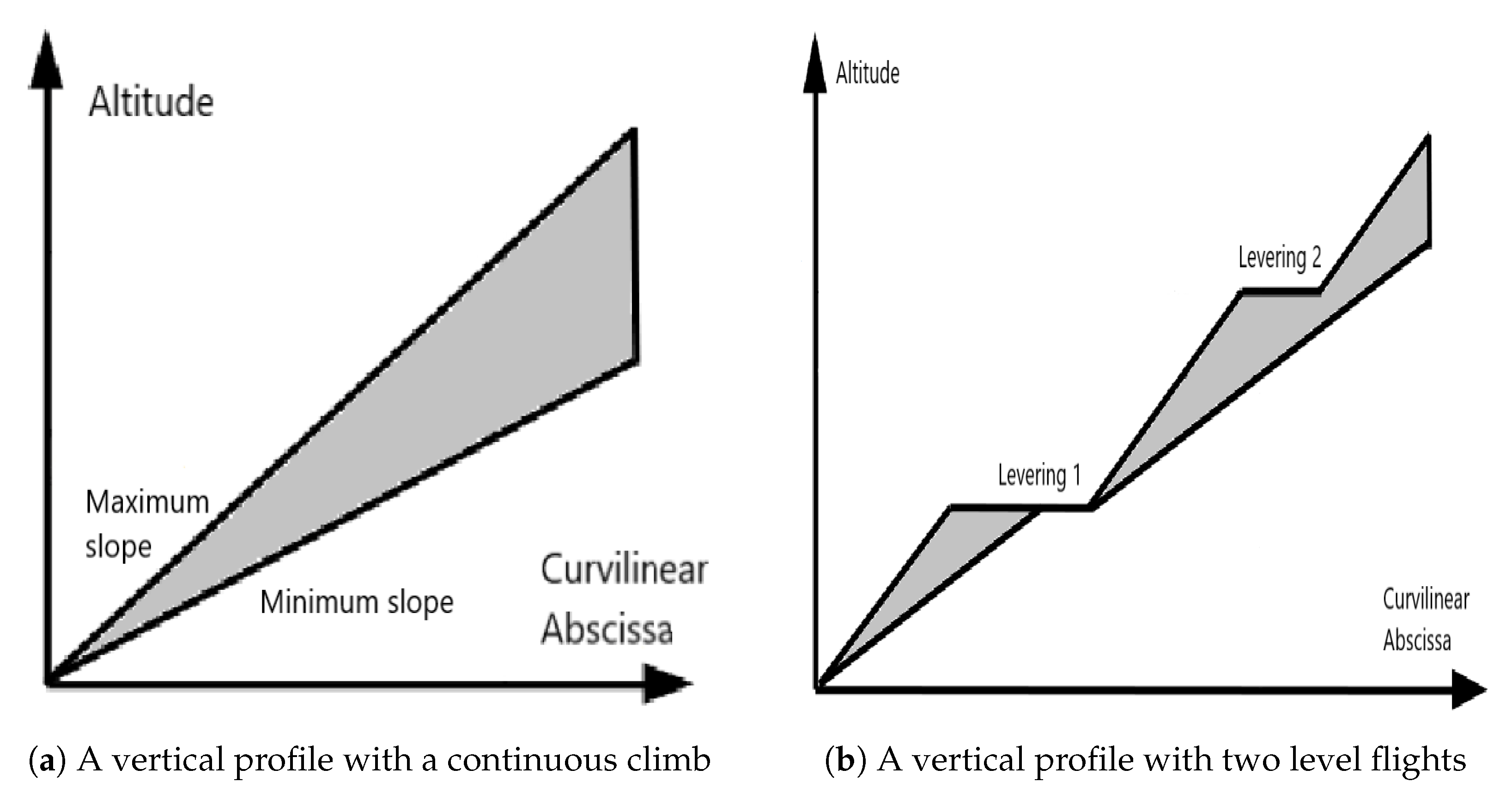
- A minimum and maximum climb and descent slope and in percentages.
- The maximum number and minimum and maximum length of the level flights (resp. , and )
3.2. Tma Discretization
Vertices
- The center is the first waypoint at which an aircraft is authorized to maneuver.
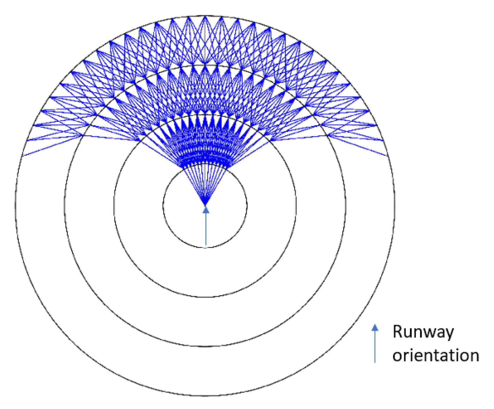
- This point will be the center of concentric layers (for example circles or squares) of increasing size, such that the last one passes through the exit point that is farthest from the center in the TMA. These layers are denoted where is the number of layers. The center itself is considered as the first layer. Layers can be any borders of an increasing family of convex sets.
- Each is then sampled to create a 2D set points where is the number of points on . Let the set of all 2D points. In the rest of the document and without loss of generality, it will be assumed that for all i, and that all exit points are located on the last layer in order to keep the notation simple.
Arcs
- All arcs are oriented, from a vertex on a layer to a vertex on the layer . The arc that connects with will be denoted .
- The arcs between (the center) and are constructed by taking into account the direction of the runway. An arc between and exists if and only if its angle with this direction is less than the maximum authorized turn angle .
- The other arcs are built recursively, layer by layer: all the arcs starting on a layer i are built before any of those starting on the layer . An arc exists if and only if there exists such that the angle formed by the segments , and is less than the maximum authorized turn angle .
3.3. Route Modeling and Decision Variables
| Algorithm 1 Construction of |
| Require:HorizontalPath = , VerticalProfile = in the binary representation, an initial altitude Altinit, a minimum slope Slopemin, a maximum slope Slopemax |
| 1: Initialization: Let = (Altinit,0,…0) and = (Altinit,0…,0) two arrays of length , = Altinit, = Altinit |
| 2: for i from 1 to do |
| 3: Let = HorizontalPath and Alti = VerticalProfile |
| 4: Let |
| 5: Let Altmin = + Slopemin and Altmax = + Slopemax |
| 6: if Alti is true then |
| 7: |
| 8: |
| 9: |
| 10: else |
| 11: Altmin |
| 12: Altmax |
| 13: |
| 14: |
| 15: end if |
| 16: end for |
| 17: return |
3.4. Constraints
- Obstacle avoidance:where d is the euclidean distance between two objects (i.e., the minimum distance between two points, one on the first object and the other on the second) and and are respectively the minimum horizontal and vertical distances to keep with an obstacle.
- Route separation: The arcs of routes i and j starting on their merge point are denoted and . The constraint is expressed as:andThis means that any two points belonging to two different routes must be horizontally separated by a minimum distance. When it is not the case, their altitudes must differ by at least a minimum vertical distance. Moreover, Equation (5) states that the angle between the two routes must be greater than a limit value at the merge point.
- Limited turn constraint:Figure 4 illustrates this constraint: it shows (in red) a path that violates it by including too sharp turns.
- Merge constraint:
- Level flights constraint: A level flight is defined as a maximum continuous portion of route on which the maximum altitude is fixed. For example, a level flight in a SID will force the altitude to be no greater than a fixed value. The constraints on level flights are imposed in order to maximize the use of continuous climb:
3.5. Objective Function
4. Resolution Approach
- Obstacle avoidance constraint: The obstacle avoidance becomes part of the objective: an extremely high cost is added to the route objective compared to the other criteria whenever an obstacle is traversed. This way, the priority of the algorithm is to avoid them, should it make a route longer, for example. Therefore, in certain very complex situations, the algorithm may return a solution that passes through obstacles
- Limited turn constraint: This constraint is affected in the same way as the obstacle avoidance constraint: whenever a route contains illicit turns, it is heavily penalized in the objective.
- Route separation: The routes are created sequentially, by decreasing the order of expected traffic flow. The aim is to prioritize the busiest routes. To handle this, all routes that have already been designed are set as obstacles regarding the design of the next ones. The airprox (routes being too close to each other) constraint then becomes similar to the obstacle constraint.
4.1. Simulated Annealing
- Initialization: A first solution is computed, that will serve as the starting point of the algorithm. In the mean time, an initial temperature is set (see Reference [33] for the choice of this temperature)
- Cooling loop:
- the result of the evaluation of the objective function for the current solution is denoted and the current temperature of the algorithm is denoted T.
- Creation of a neighbor for the current solution
- Evaluation of the objective function for the neighbor
- If the objective is improved, the new solution is accepted as the starting point for the next iteration. If not, it is accepted with a probability .
- The temperature is decreased
- Stopping criterion: The algorithm stops when the temperature drops below a limit value. It can also stop earlier if there is a way to know the value of the objective for the optimal solution. In this case, the SA stops if the objective attains this value.
4.2. Generating a Solution
4.2.1. Creating the Merge Layers
4.2.2. Finding One Path
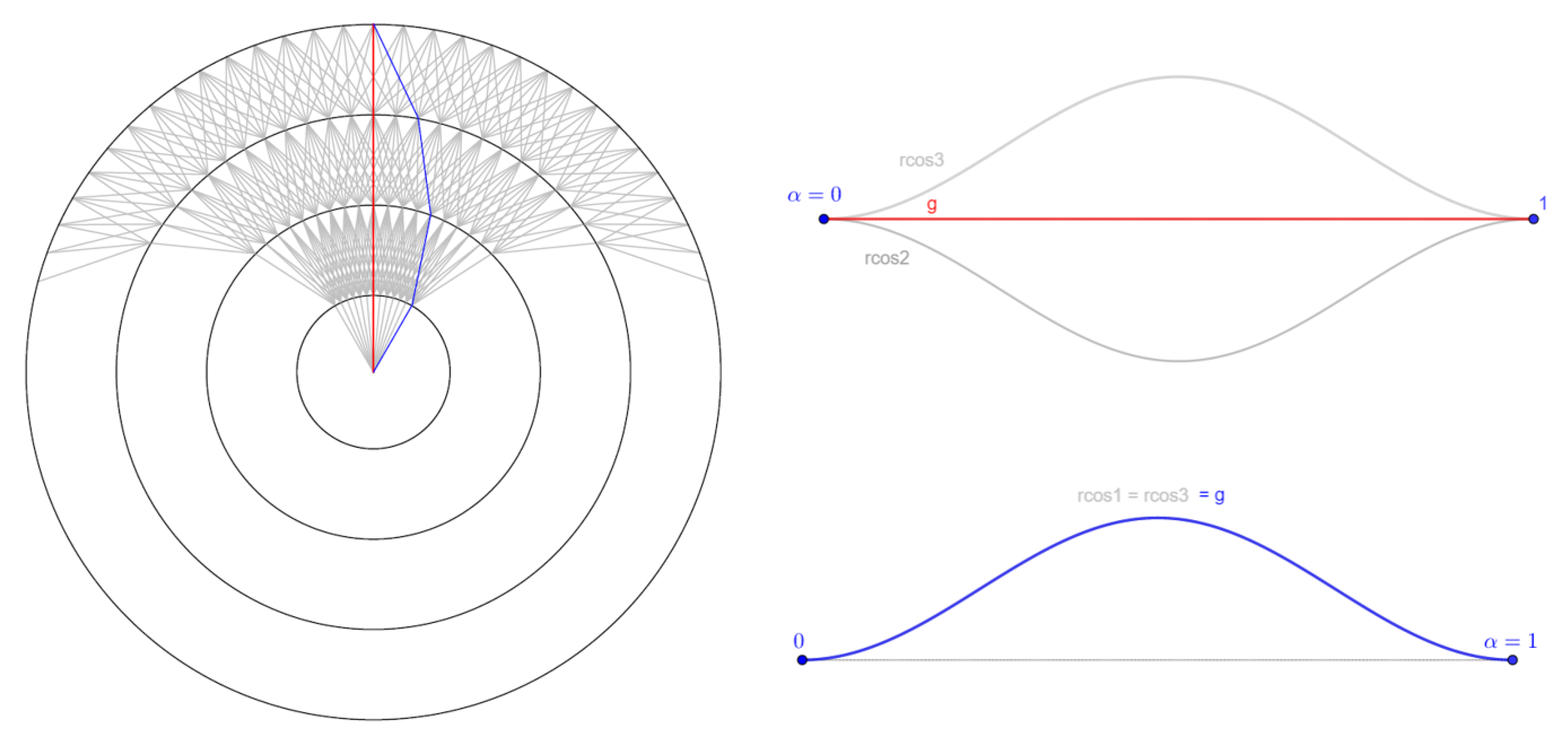
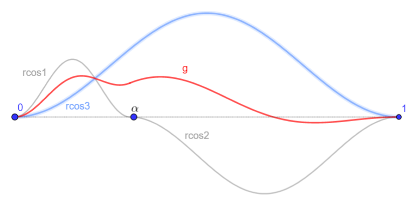
- A number and two signs are randomly chosen.
- Three amplitude values in are set. These values can be chosen randomly, but in this work, they are decrease down to zero with the progress of the SA. This allows to explore the state space when the temperature is high and focus on a narrower neighborhood when it is low.
- Three raised cosine functions are generated (see Figure 6):
- A function g is defined as on , by setting on and on
- The coefficients are chosen so that the route to find has the same shape relatively to the segment than g has relatively to
4.2.3. Creating a Set of Paths
| Algorithm 2 Generating a set of routes |
| Require: The center center, the exits ordered by decreasing traffic flow. |
| 1: Initialization: Set a starting point Start = center, an null matrix Biases of size . |
| 2: for i from 1 to do |
| 3: Fill Biases with the biases using the raised cosine formula. If a route begins on a layer greater than 1 or ends before the layer , the corresponding cells of Biases are set to a default value less than or greater than 1. |
| 4: Set the arcs costs according to the coefficients in Biases |
| 5: Set Shortest path from Start to |
| 6: Set Start = a randomly selected intersection of one of with a merge layer, that is not already a merge point. |
| 7: end for |
| 8: return |
4.3. Generating a Neighbor
- The route of connection (see step 6 in Algorithm 2)
- The layer on which a route connects to an other (i.e., the merge layer)
- The coefficients for the arcs bias algorithm
- The level flights on a route (choice of the )
- The merge layers, that can be changed. In this case, all routes are computed again. This is meant to induce exploration at the beginning of the search
4.4. Evaluation
- The grid covers at least the area of the graph
- Each cell of the grid is a square whose side length is not greater than the minimum horizontal separation (for example, 1 NM in this work).
- Each cell holds the following information:
- –
- The height of the highest ground obstacle that can be found in this cell (mountain, antenna, building…)
- –
- The minimum and maximum altitudes of a forbidden flight zone in this area (if any)
- –
- The density of population on the ground (if any)
5. Simulation Results
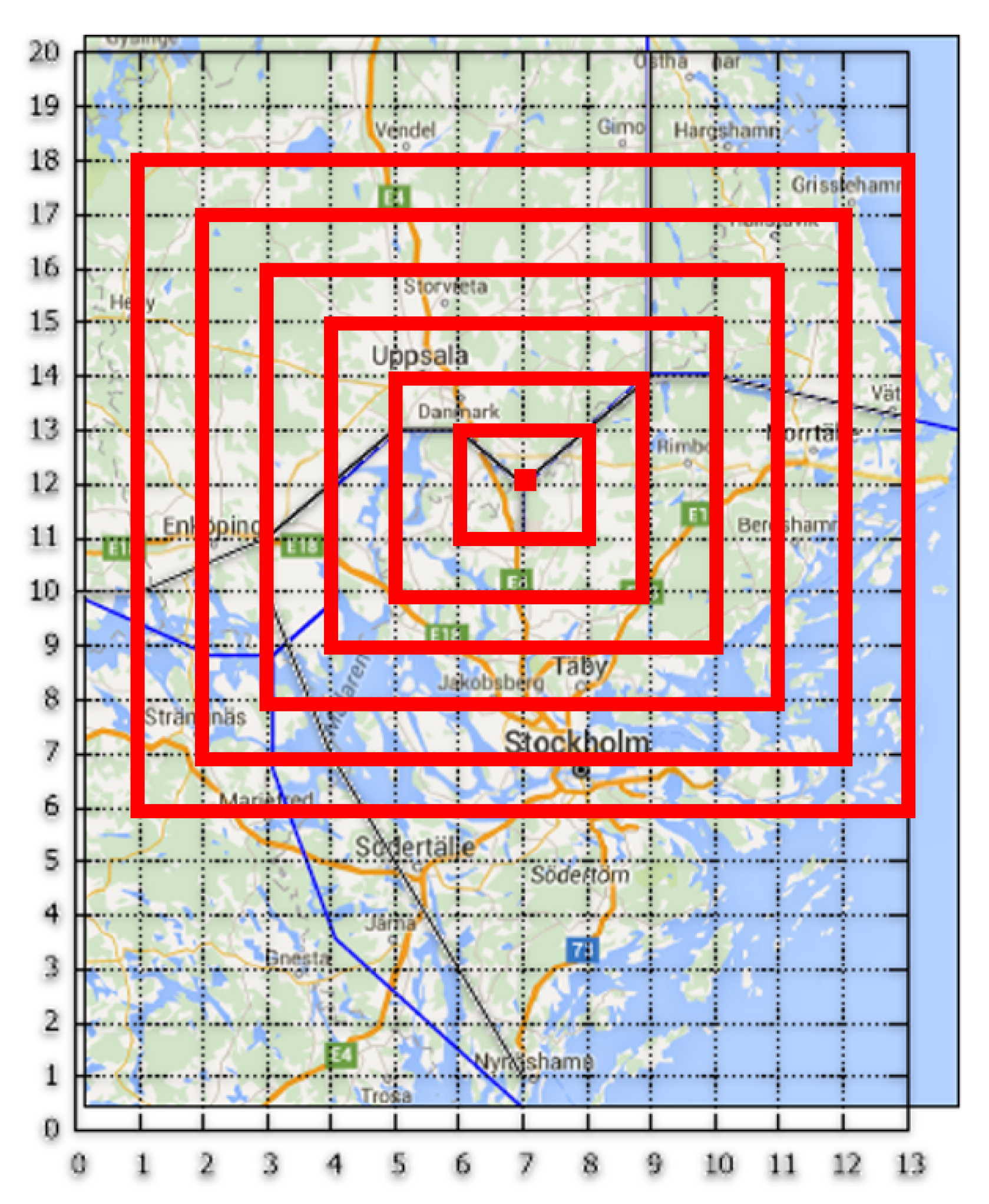
5.1. The Stockholm Instance
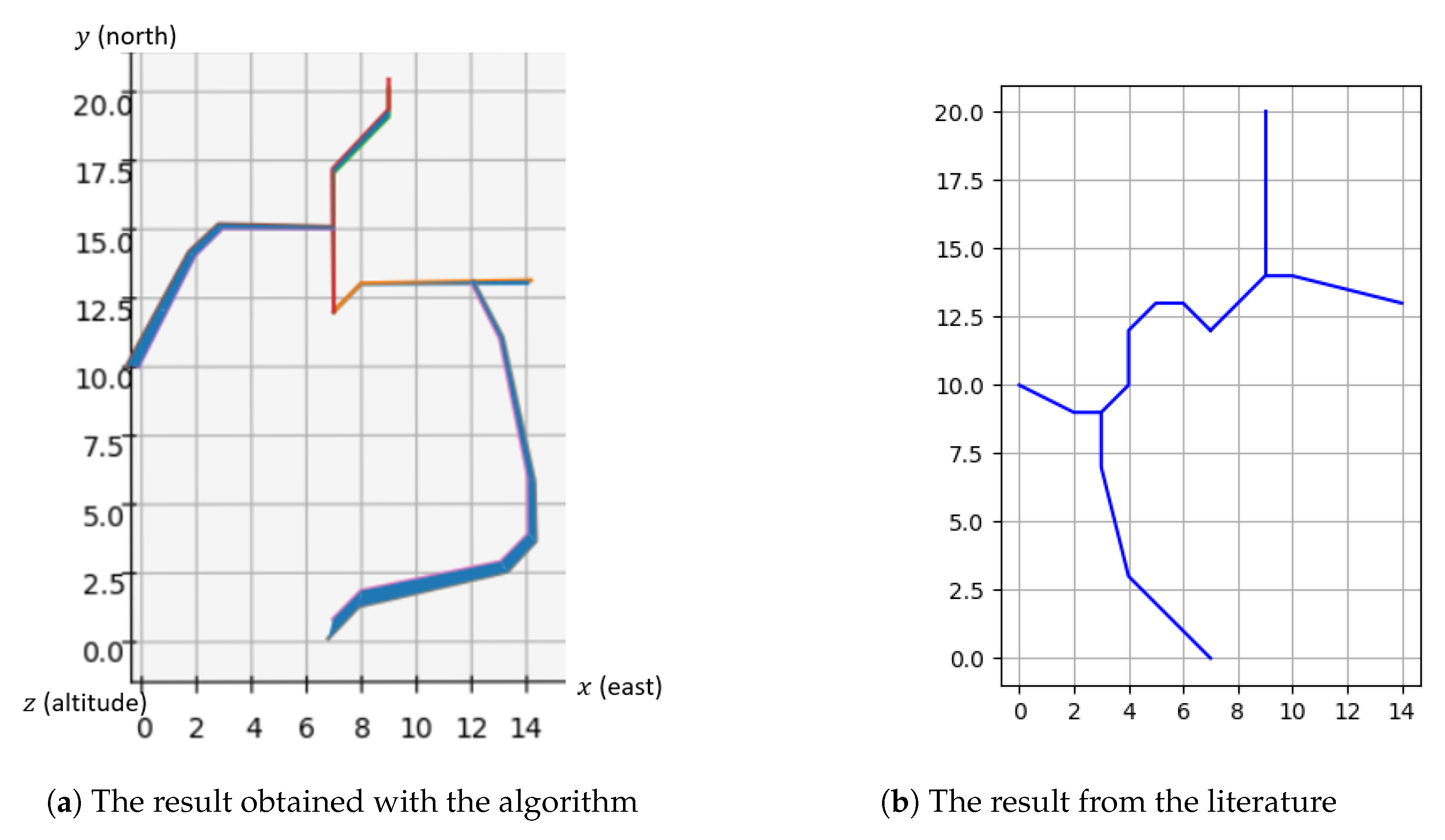
- Center = (7,12)
- The runway is oriented by the vector
- The exits are located at (14,13), (9,20), (0,10), (7,0) by decreasing order of traffic flow
- The traffic flows are all equal
- The altitude range of the exit points is not relevant (so all ranges are accepted in the solution)
- Maximum turn angle °
- Minimum angle at merge points °
- The minimum and maximum slopes and are not relevant
- The number and minimum and maximum length of the level flights , and are not relevant
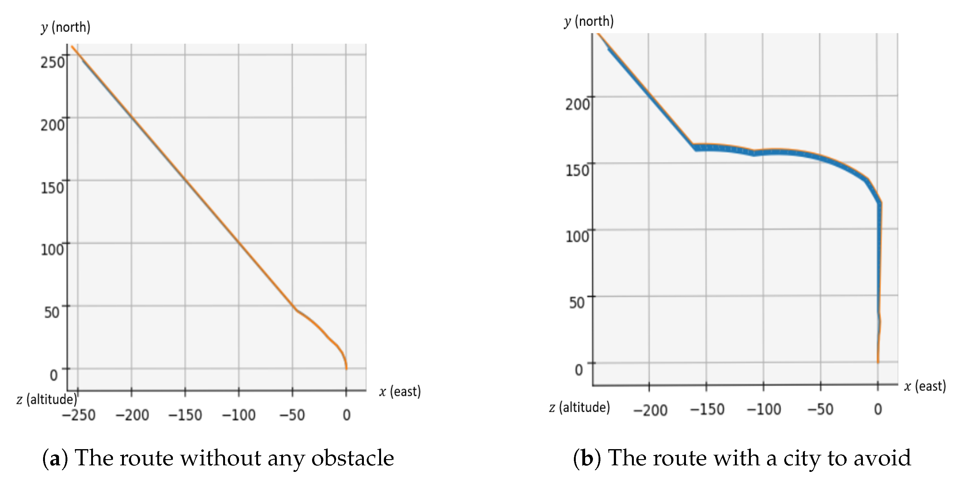
- The cities are considered as obstacles and are as described in Table 1
5.2. Artificial Problem
- Center: (0,0,0)
- The runway is oriented by the vector
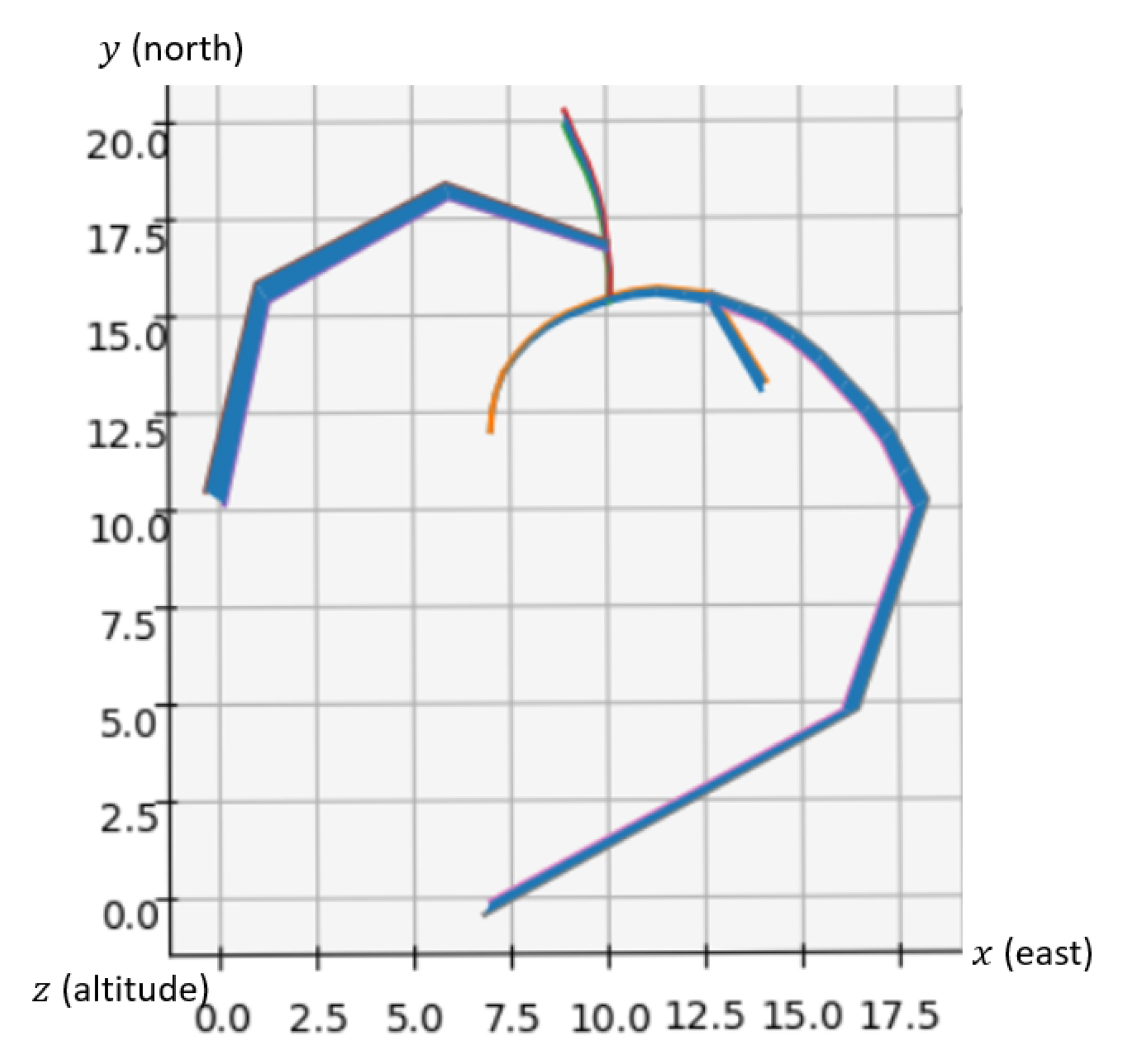
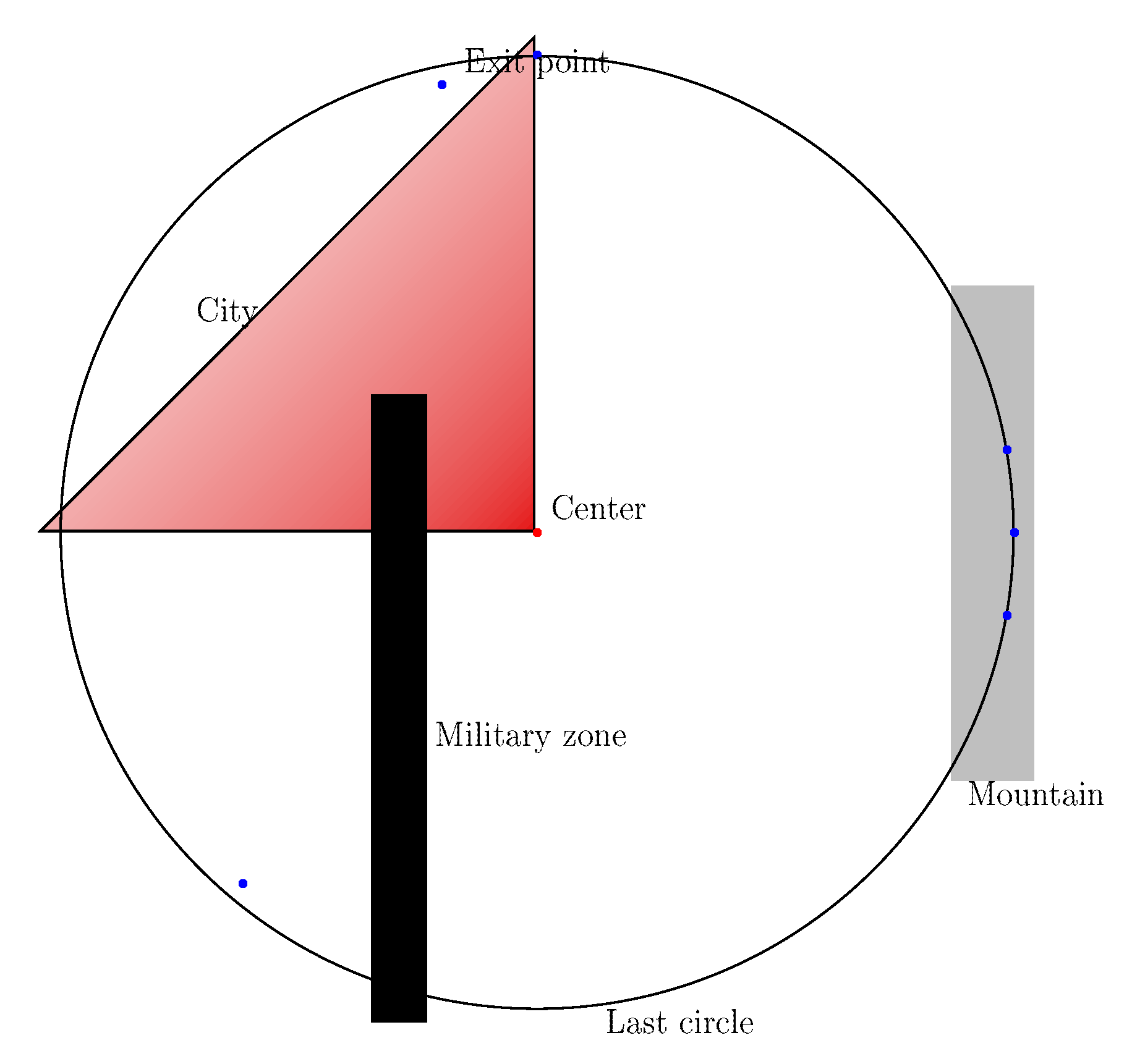
- In polar coordinates, the exits are located at (346, 0°), (346, 10°), (346, 350°), (346, 90°), (328.5, 135°), (328.5, 230°) by decreasing order of traffic flow
- The traffic flows, by decreasing order, are 26.67%, 24%, 21.33%, 13.33%, 12%, 2.67%
- The altitude range of the exit points is not relevant (so all ranges are accepted in the solution)
- Maximum turn angle °
- Minimum angle at merge points °
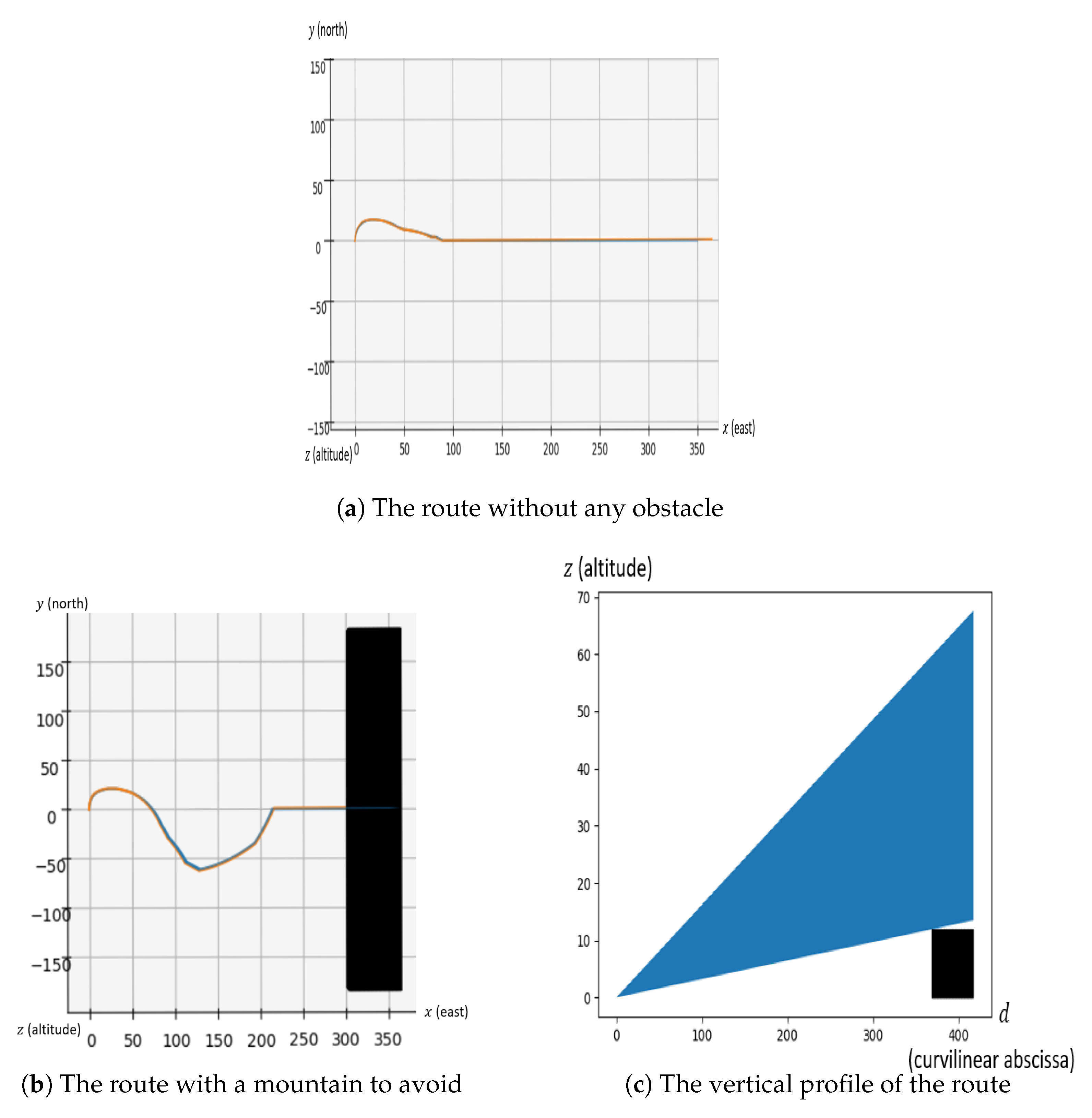
- Minimum slope : 3.24%
- Maximum slope : 16.2%.
- The maximum number of level flights
- The minimum length of the level flights was set to NM and the maximum length is not relevant here
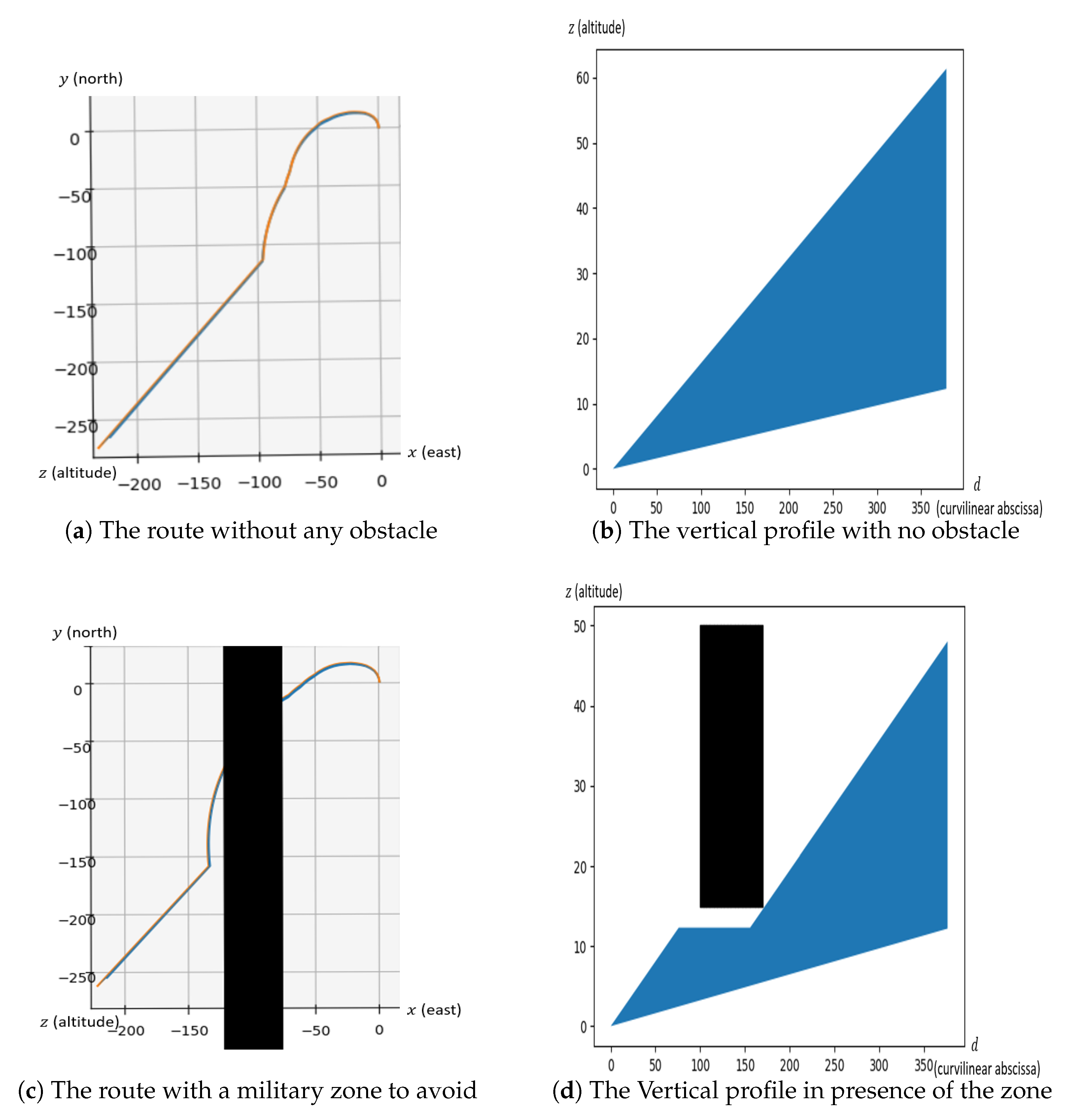
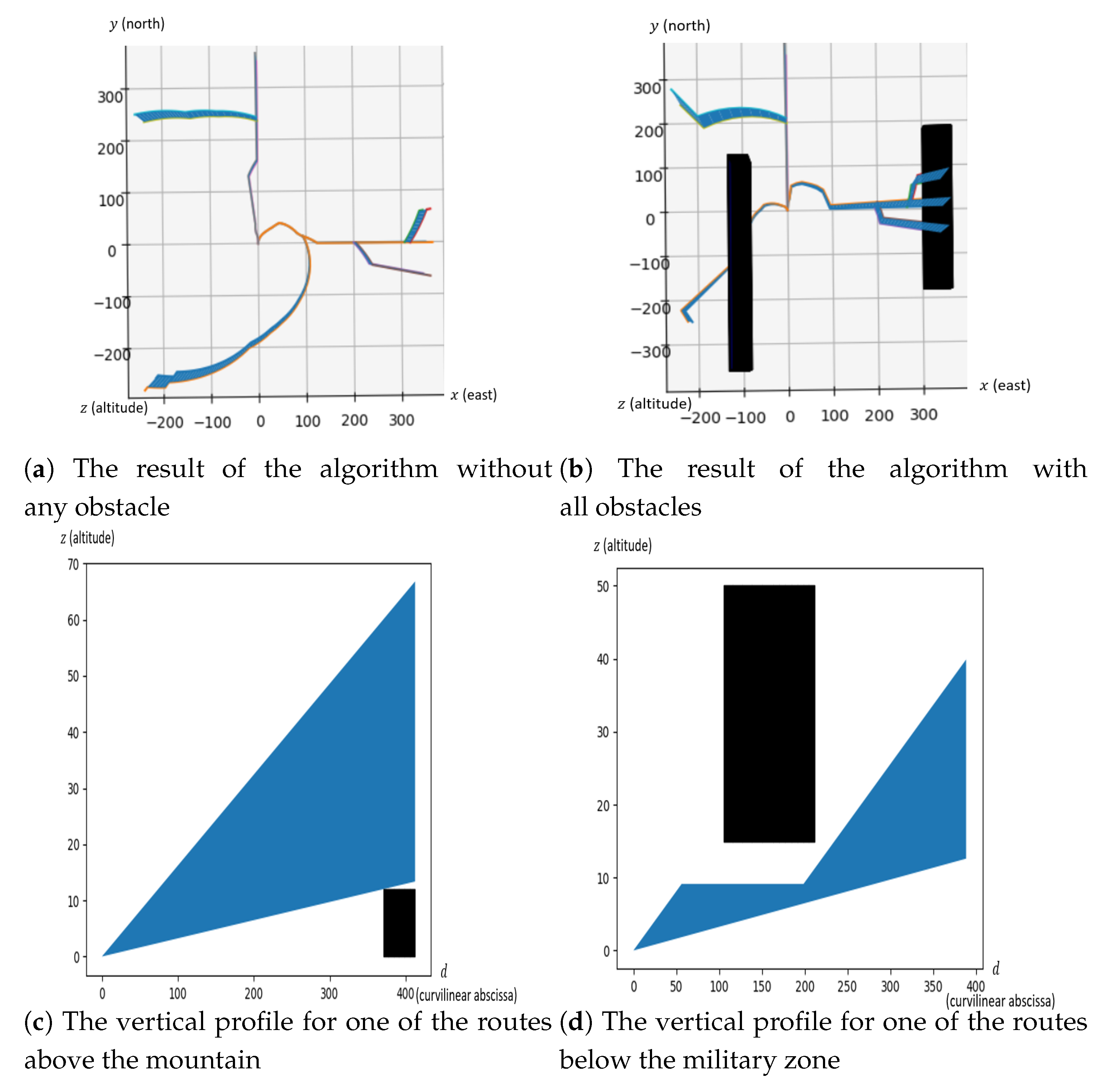
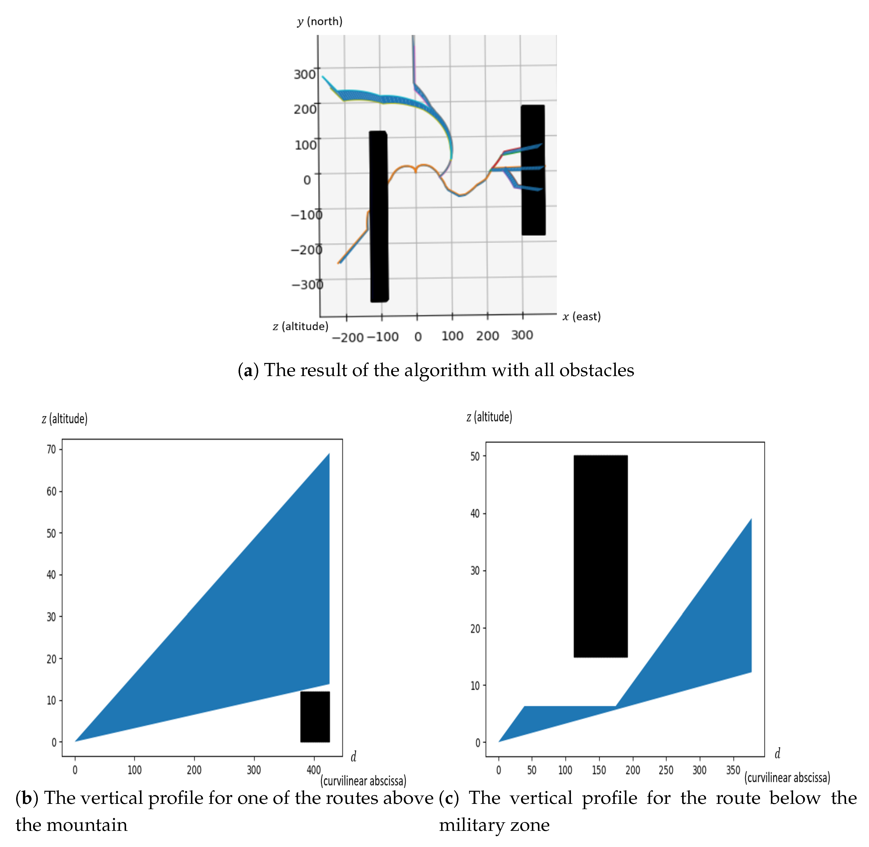
- The cities and obstacles are given in Table 2
5.2.1. One Route Design and One Obstacle
5.2.2. Six Routes Design with All Obstacles
6. Conclusions
Author Contributions
Funding
Conflicts of Interest
Nomenclature
| the entry or exit points of the TMA | |
| the expected traffic flow on the entry/exit point | |
| an air route connecting to the runway | |
| the projection of route on the horizontal plan | |
| the vertical profile of route | |
| , | the minimal and maximal altitudes that an aircraft can attain at distance s from the starting point of route |
| the set of all obstacles | |
| an obstacle given by its base polygon , lower and higher altitudes (resp. and ) | |
| T | the set of all cities |
| a city given by its location in the plane as a polygon , and the density function that gives the population density at a given point in the city | |
| and | the minimum and maximum climb slopes |
| and | respectively the minimum horizontal and vertical distances to keep with an obstacle |
| the minimum distance to keep between two merge points | |
| the minimum angle between two routes at a merge point | |
| the maximum authorized turn angle | |
| the maximum number of level flights | |
| , | the minimum and maximum length of a level flight |
References
- ICAO. Required Navigation Performance Authorization Required (RNP AR) Procedure Design Manual; ICAO: Montreal, QC, Canada, 2009. [Google Scholar]
- ICAO. Continuous Climb Operations (CCO) Manual; ICAO: Montreal, QC, Canada, 2010. [Google Scholar]
- ICAO. Continuous Descent Operations (CDO) Manual; ICAO: Montreal, QC, Canada, 2010. [Google Scholar]
- Dijkstra, E.W. A Note on Two Problems in Connexion with Graphs. Numer. Math. 1959, 1, 269–271. [Google Scholar] [CrossRef]
- Bellman, R. On a Routing Problem. Q. Appl. Math. 1958, 16, 87–90. [Google Scholar] [CrossRef]
- LaValle, S.M. Planning Algorithms; Cambridge University Press: Cambridge, UK, 2006. [Google Scholar]
- Delahaye, D.; Puechmorel, S.; Tsiotras, P.; Feron, E. Mathematical Models for Aircraft Trajectory Design: A Survey. In Air Traffic Management and Systems: Selected Papers of the 3rd ENRI International Workshop on ATM/CNS (EIWAC2013); Springer: Tokyo, Japan, 2014; pp. 205–247. [Google Scholar]
- Lozano-Pérez, T.; Wesley, M.A. An algorithm for Planning Collision-Free Paths Among Polyhedral Obstacles. Commun. ACM 1979, 22, 560–570. [Google Scholar] [CrossRef]
- Liu, Y.H.; Arimoto, S. Path Planning Using a Tangent Graph for Mobile Robots among Polygonal and Curved Obstacles. Int. J. Robot. Res. 1992, 11, 376–382. [Google Scholar] [CrossRef]
- Kim, D.; Yu, K.; Cho, Y.; Kim, D.; Yap, C. Shortest Paths for Disc Obstacles. In Proceedings of the International Conference on Computational Science and Its Applications (ICCSA 2004), Assisi, Italy, 14–17 May 2004; Springer: Berlin/Heidelberg, Germany, 2004; pp. 62–70. [Google Scholar]
- Pierre, S.; Delahaye, D.; Cafieri, S. Aircraft Trajectory Planning with Dynamical Obstacles by Artificial Evolution and Convex Hull Generations. In Proceedings of the 2015 ENRI International Workshop on ATM/CNS (EIWAC2015), Tokyo, Japan, 17–19 November 2015. [Google Scholar]
- Zhou, J. Optimal Design of SIDs/STARs in Terminal Maneuvering Area. Ph.D. Thesis, Université Toulouse 3 Paul Sabatier, Toulouse, France, 2017. [Google Scholar]
- Bygi, M.N.; Ghodsi, M. 3D Visibility Graph. In Proceedings of the Computational Science and its Applications, Kuala Lumpur, Malaysia, 26–29 August 2007. [Google Scholar]
- Gianazza, D.; Durand, N.; Archambault, N. Allocating 3D-trajectories to air traffic flows using A* and genetic algorithms. In Proceedings of the International Conference on Computational Intelligence for Modelling, Control and Automation (CIMCA 2004), Queensland, Australia, 12–14 July 2004. [Google Scholar]
- Zhou, J.; Cafieri, S.; Delahaye, D.; Sbihi, M. Optimizing the Design of a Route in Terminal Maneuvering Area Using Branch and Bound. In Proceedings of the 2015 ENRI International Workshop on ATM/CNS (EIWAC2015), Tokyo, Japan, 17–19 November 2015. [Google Scholar]
- Pfeil, D.M. Optimization of Airport Terminal-Area Air Traffic Operations under Uncertain Weather Conditions. Ph.D. Thesis, Massachusetts Institute of Technology, Cambridge, MA, USA, 2011. [Google Scholar]
- Polishchuk, V. Generating Arrival Routes with Radius-to-Fix Functionalities. In Proceedings of the 7th International Conference on Research in Air Transportation (ICRAT 2016), Philadelphia, PA, USA, 20–24 June 2016. [Google Scholar]
- Zhou, J.; Cafieri, S.; Delahaye, D.; Sbihi, M. Optimization of Arrival and Departure Routes in Terminal Maneuvering Area. In Proceedings of the 6th International Conference on Research in Air Transportation (ICRAT 2014), Istanbul, Turkey, 26–30 May 2014. [Google Scholar]
- Lawler, E.L.; Wood, D. Branch-and-Bound Methods: A Survey. Oper. Res. 1966, 16, 699–719. [Google Scholar] [CrossRef]
- Hart, P.; Nilsson, N.; Raphael, B. A Formal Basis for the Heuristic Determination of Minimum Cost Paths. IEEE Trans. Syst. Sci. Cybern. 1968, 4, 100–107. [Google Scholar] [CrossRef]
- Ferguson, D.; Likhachev, M.; Stentz, A. A Guide to Heuristic-based Path Planning. In Proceedings of the International Workshop on Planning under Uncertainty for Autonomous Systems, International Conference on Automated Planning and Scheduling (ICAPS), Monterey, CA, USA, 5–10 June 2005. [Google Scholar]
- Kirkpatrick, S.; Gelatt, C.D.; Vecchi, M.P. Optimization by simulated annealing. Science 1983, 220, 671–680. [Google Scholar] [CrossRef]
- Holland, J.H. Adaptation in Natural and Artificial Systems, 1st ed.; University of Michigan Press: Ann Arbor, MI, USA, 1975; reprinted by MIT Press: Cambridge, MA, USA, 1992. [Google Scholar]
- Dreo, J.; Petrowski, P.; Siarry, P.; Taillard, E. Metaheuristics for Hard Optimization; Springer: Berlin/Heidelberg, Germany, 2005. [Google Scholar]
- Eurocontrol. Guidance Material for the Design of Terminal Procedures for Area Navigation (DME/DME, B-GNSS, Baro-VNAV and RNP-RNAV); Eurocontrol: Brussels, Belgium, 2003. [Google Scholar]
- Eurocontrol. Guidance Material for the Design of Terminal Procedures for DME/DME and GNSS Area Navigation; Eurocontrol: Brussels, Belgium, 1999. [Google Scholar]
- Skybrary. Aircraft Performances. Available online: https://www.skybrary.aero/index.php/Category:Manufacturer (accessed on 25 January 2019).
- Guys, L. Planification de Trajectoires d’Avions sans Conflit: Fonctions Biharmoniques et Fonction de Navigation Harmonique. Ph.D. Thesis, Universite Toulouse 3 Paul Sabatier, Toulouse, France, 2014. [Google Scholar]
- Dougui, N.E. Planification de Trajectoires Avion: Approche par Analogie Lumineuse. Ph.D. Thesis, Universite Toulouse 3 Paul Sabatier, Toulouse, France, 2011. [Google Scholar]
- ICAO. Aircraft Operations (PANS-OPS); ICAO: Montreal, QC, Canada, 2014. [Google Scholar]
- Schäffer, B.; Zellmann, C.; Pluess, S.; Eggenschwiler, K.; Bütikofer, R.; Wunderli, J. Sound source data for aircraft noise calculations—State of the art and future challenges. In Proceedings of the EURONOISE 2012, Prague, Czech Republic, 10–13 June 2012. [Google Scholar]
- Federal Aviation Administration. Aircraft Noise Levels. Available online: https://www.faa.gov/about/office_org/headquarters_offices/apl/noise_emissions/aircraft_noise_levels/ (accessed on 13 April 2019).
- Delahaye, D.; Chaimatanan, S.; Mongeau, M. Simulated Annealing: From Basics to Applications; Springer: Cham, Switzerland, 2018; pp. 1–35. [Google Scholar]
- Granberg, T.A.; Polishchuk, T.; Polishchuk, V.; Schmidt, C. Automatic Design of Aircraft Arrival Routes with Limited Turning Angle. In Proceedings of the 16th Workshop on Algorithmic Approaches for Transportation Modelling, Optimization, and Systems (ATMOS16), Aarhus, Denmark, 25 August 2016. [Google Scholar]
| Obstacle | |
|---|---|
| Enköping | (((1,10);(3,10);(3,12);(1,12)), 0, ) |
| Stockholm | (((7,6);(9,6);(9,8);(7,8)), 0, ) |
| Uppsala | (((5,13);(6,13);(6,15);(5,15)), 0, ) |
| Sodertäle | (((5,4);(5,5);(6,5);(6,4)), 0, ) |
| Obstacle Number | Obstacle Type | or |
|---|---|---|
| 1 | Mountain | (((300,−180); (300,178); (359,178); (359,−180)), 0, 12) |
| 2 | City | (((−2,1); (−360,1); (−2359)), ) |
| 3 | Military Area | (((−120,−355); (−80,−355); (−80,100); (−80,−355)), 15, 50) |
| Test Case | (# of Layers, # of Points per Layer) | Computation Time | Obstacles (Table Number) | Routes Length with Obstacles | Graph Weight with Obstacles | ||
|---|---|---|---|---|---|---|---|
| Routes Length without Obstacles | Graph Weight without Obstacles | ||||||
| Stockholm | (13,*) | 2.67 s | All (1) | 51.81 | 43.39 | ||
| ** | ** | ||||||
| (25,360) | 1 min 48 s | All (1) | 71.47 | 52.90 | |||
| ** | ** | ||||||
| Single route | (50,72) | 9 min 20 s | 1 (2) | 417.36 | 417.36 | ||
| 358.61 | 358.61 | ||||||
| (50,72) | 8 min 53 s | 2 (2) | 394.50 | 394.50 | |||
| 344.79 | 344.79 | ||||||
| (50,72) | 9 min 0 s | 3 (2) | 376.17 | 376.17 | |||
| 378.83 | 378.83 | ||||||
| Six routes | (50,72) | 4 min 08 s | 1,2,3 (2) | 2970.13 | 1874.41 | ||
| 2701.98 | 1673.86 | ||||||
| (100,360) | 19 min 38 s | 1,2,3 (2) | 2928.00 | 2096.64 | |||
| 2568.06 | 1601.70 |
© 2019 by the authors. Licensee MDPI, Basel, Switzerland. This article is an open access article distributed under the terms and conditions of the Creative Commons Attribution (CC BY) license (http://creativecommons.org/licenses/by/4.0/).
Share and Cite
Chevalier, J.; Delahaye, D.; Sbihi, M.; Marechal, P. Departure and Arrival Routes Optimization Near Large Airports. Aerospace 2019, 6, 80. https://doi.org/10.3390/aerospace6070080
Chevalier J, Delahaye D, Sbihi M, Marechal P. Departure and Arrival Routes Optimization Near Large Airports. Aerospace. 2019; 6(7):80. https://doi.org/10.3390/aerospace6070080
Chicago/Turabian StyleChevalier, Jeremie, Daniel Delahaye, Mohammed Sbihi, and Pierre Marechal. 2019. "Departure and Arrival Routes Optimization Near Large Airports" Aerospace 6, no. 7: 80. https://doi.org/10.3390/aerospace6070080
APA StyleChevalier, J., Delahaye, D., Sbihi, M., & Marechal, P. (2019). Departure and Arrival Routes Optimization Near Large Airports. Aerospace, 6(7), 80. https://doi.org/10.3390/aerospace6070080


