Article

An Insight on the Crashworthiness Behavior of a Full-Scale Composite Fuselage Section at Different Impact Angles

1
Department of Engineering, University of Campania “Luigi Vanvitelli”, via Roma 29, 81031 Aversa CE, Italy
2
Italian Aerospace Research Centre (CIRA), via Maiorise snc, 81043 Capua CE, Italy
*
Author to whom correspondence should be addressed.
These authors contributed equally to this work.
Aerospace 2019, 6(6), 72; https://doi.org/10.3390/aerospace6060072
Submission received: 16 May 2019 / Revised: 10 June 2019 / Accepted: 16 June 2019 / Published: 18 June 2019
(This article belongs to the Special Issue Crashworthiness Design for Aviation Safety)

Abstract

:
In the present paper, advanced numerical methodologies have been adopted to investigate the influence of impact angle on the crashworthiness behavior of a composite fuselage section. The analyzed fuselage section, made of unidirectional fiber-reinforced material, woven fabric material, and aluminum material, is representative of a regional aircraft fuselage. Two different angles of impact with rigid ground have been investigated and reported: Perpendicularly to the ground and with a pitch angle of 3 degrees with respect to the ground. The adopted numerical models have been preliminarily validated with experimental data from a drop test on a full-scale fuselage section, in terms of deformations and failure location and progression. The correlation between the numerical model and the experimental test has enabled evaluation of the effect of the impact angle on the deformation and damage in the sub-cargo floor area.

Graphical Abstract

1. Introduction

The increasing use of civil aircraft transport requires more and more attention to aircraft design to ensure occupant safety and structural integrity by means of controlled kinetic energy absorption, ensuring a level of deceleration within a given threshold [1,2,3,4] under an impact event. This design approach, also known as the crashworthiness design, is deeply influenced by the geometrical conditions, impact parameters, and material interactions [5,6] related to the impact phenomena’s great complexity [7,8,9,10]. In order to design a structure capable of absorbing the impact load transmitted between the ground and the fuselage, guaranteeing a satisfactory level of occupant safety in accordance with the Federal Aviation Administration (FAA) standards [1], several robust numerical models have been developed in order to reduce the costly experimental tests, which are often affected by uncertainty due to boundary conditions, such as the material characteristics, impact velocity, and actual dimensions [11]. Energy absorption in conventional metal structures occurs as plastic deformations lead to collapse. The use of numerical models allows, with good approximation, to predict the degree of dissipated energy and to achieve an optimal fuselage sub-components design. As an example, good approximation between experimental tests and finite element numerical analyses for a subfloor helicopter structure has been reported in Reference [12]. Other authors demonstrate the integrity of a fuel tank during a crash condition [13]. In recent decades, composite materials are replacing conventional metal materials, due to their characteristics of high specific stiffness and strength. Fiber composite materials with epoxy matrix do not have a plastic deformation phase [14], leading to more complex kinetic energy absorption mechanisms during the impact events involving the interaction between the different composite phases. Complex structures, such as fuselages, transmit the load from the impact point to the whole structure, resulting in a more extended and difficult to predict absorption of the kinetic energy [15,16,17,18,19,20]. Several works on civil transport aircraft crashworthiness have highlighted the influence of the stiffness of the floor of the cabin and of the cargo subfloor components on the energy absorption behavior [21,22,23,24]. Indeed, the cargo subfloor area first experiences the impact with the ground, absorbing most of the kinetic energy. In particular, the impact energy is absorbed by the frame and the hinges [24,25,26,27,28,29,30,31,32,33]. The fuselage frame can dissipate almost half of the impact energy during the impact. Therefore, fiber-reinforced composite structures such as sandwich panels can be adopted to increase energy absorption [34,35]. The bars between the cargo area and the cabin, although first designed as a cabin primary structures, could be used as a kinetic energy absorber without changing the aircraft structural characteristic. As already remarked, the study of the energy absorption in the form of damage energy or plastic deformation energy assumes a prominent role during the crashworthy design. However, investigations on the whole airplane structure crashworthiness are still very limited nowadays. To understand the energy dissipation mechanism occurring during a crash event, reliable numerical tools and methods are needed to be used, due to the airplane structure complexity. Indeed, accurate numerical modeling requires the appropriate selection of the element type [36]. As a matter of fact, three-dimensional elements are mandatory to study the complex stress distribution, including shear stress, arising from the impact event [37,38].
In this work, a drop test of a composite fuselage section is investigated, focusing on the impact angle with the rigid ground. During the experimental test, an impact angle has been generated by the pitch rotation of the fuselage during the descending phase due to unbalanced masses on the floor beams. This effect can be considered representative of an impact on a non-plane surface. In particular, the focus of this work is to investigate the effect of such an impact angle on the structural deformations and the failure of the sub-cargo floor. In order to better analyze the impact phenomenon under investigation, numerical simulations have been performed by using the commercial Finite Element Method (FEM) software ABAQUS explicit, and the pitch angle has been taken into account by imposing a rotation angle to the rigid plate simulating the ground. The fiber-reinforced composite fuselage components have been modeled by means of three-dimensional continuum shell elements. Despite these elements having a shell formulation, they are characterized by a three-dimensional shape. Hence, it is possible to take into account the effects of transverse shear deformation and the thickness change, providing a more refined through-the-thickness response.
In Section 2, a brief theoretical background on the damage models adopted in the frame of numerical simulations is given. In Section 3, the geometrical and numerical modeling activities on the fuselage subcomponents are introduced, while the obtained numerical results for the two investigated impact angles (90° and 87°) and comparisons with experimental data are reported in Section 4. Finally, in Section 5, the influence of impact angle on the failure onset and propagation within the sub-cargo fuselage area is discussed.

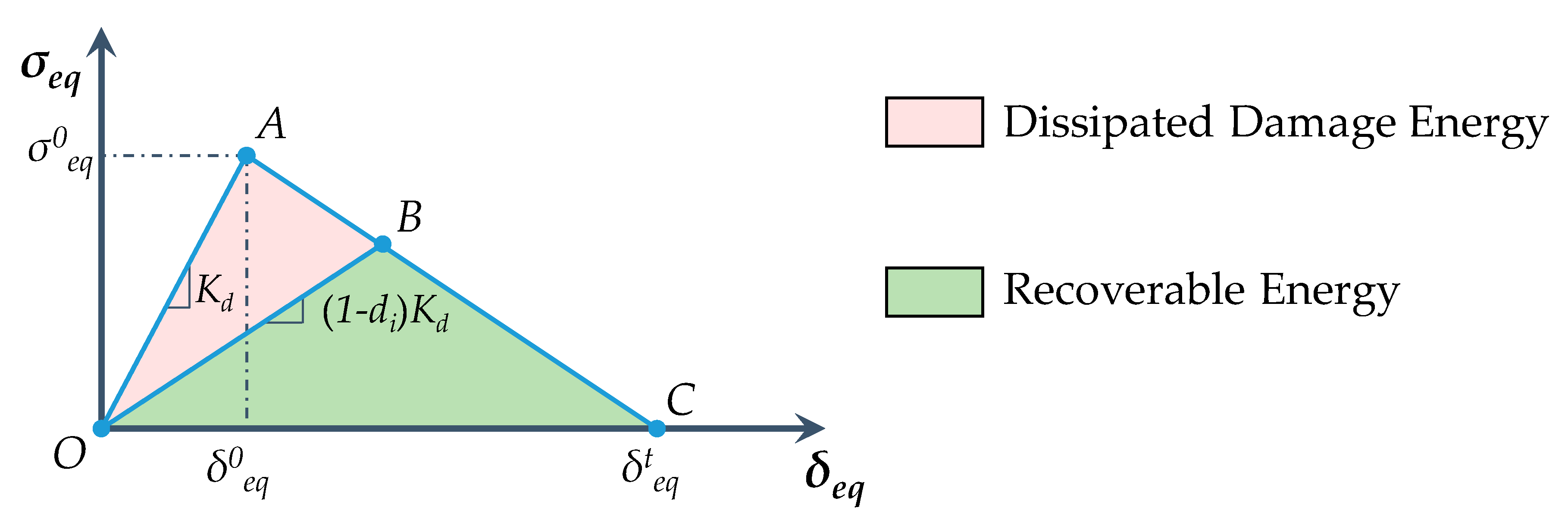
2. Theoretical Background

In this section, the intra-laminar progressive damage models adopted for the numerical simulations are described in detail. Hashin’s failure criteria have been adopted to predict fiber breakage and matrix cracking onset. Moreover, conventional ductile criteria joined with a bilinear material model have been adopted to simulate the damage progression [39].
Hashin’s failure onset criteria, adopted in this work, enable prediction of the fiber and matrix failure onsets in compression or tension for each mode. The criteria reported in Equations (1)–(4) introduce four different limit parameters: Fft fiber tensile, Ffc fiber compressive, Fmt matrix tensile, and Fmc matrix compressive.
F f t = ( σ 11 X T ) 2 + ( σ 12 S L ) 2 = 1
F f c = ( σ 11 X C ) 2 = 1
F m t = ( σ 22 Y T ) 2 + ( σ 12 S L ) 2 = 1
F m c = ( σ 22 2 S T ) 2 + [ ( Y C 2 S T ) 2 1 ] σ 22 Y C + ( σ 12 S L ) 2 = 1
where σ ^ 11 , σ ^ 22 , σ ^ 12 are the components of the effective stress tensor along fiber direction, matrix direction, and shear; XT, XC, YT, YC, SL, and ST are, respectively, the fiber tensile, fiber compressive, matrix tensile, matrix compressive, shear strength in longitudinal and transversal direction. The evolution of the damage for separate failure modes is explained in Figure 1.
The point A in Figure 1 identifies the point in which Hashin’s criteria are satisfied. Kd is the undamaged material stiffness. The segment AC is the damage evolution phase up to point C, where the element is completely damaged. The partially damaged phase (point B) is evaluated with a gradual stiffness material degradation. The material stiffness degradation coefficient di is calculated for each mode in according with Equation (5):
d i = δ i , e q t ( δ i , e q δ i , e q 0 ) δ i , e q ( δ i , e q t δ i , e q 0 ) ; δ i , e q 0 δ i , e q δ i , e q t ; i ( f c , f t , m c , m t )
The maximum equivalent displacement reached in point C is calculated in accordance with Equation (6):
δ i , e q t = 2 G i , c σ i , e q 0
where σ i , e q 0 and δ i , e q 0 are, respectively, the equivalent stress and displacement at the Hashin limit condition. Gi,c is the material fracture toughness of the i-th failure mode, which is equal to the area of the triangle OAC, shown in Figure 1. Finally, the area of the triangle OBC corresponds to the recoverable energy, while the area of the triangle OAB is related to the area dissipated due to the damages. In Table 1, the equations to evaluate the equivalent stress and displacement are reported.

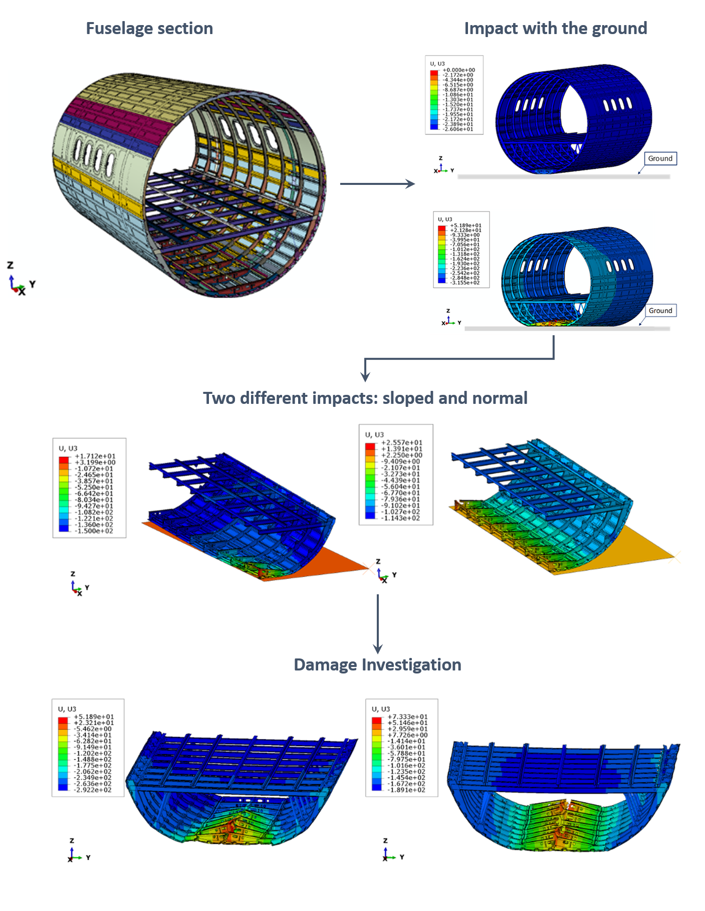
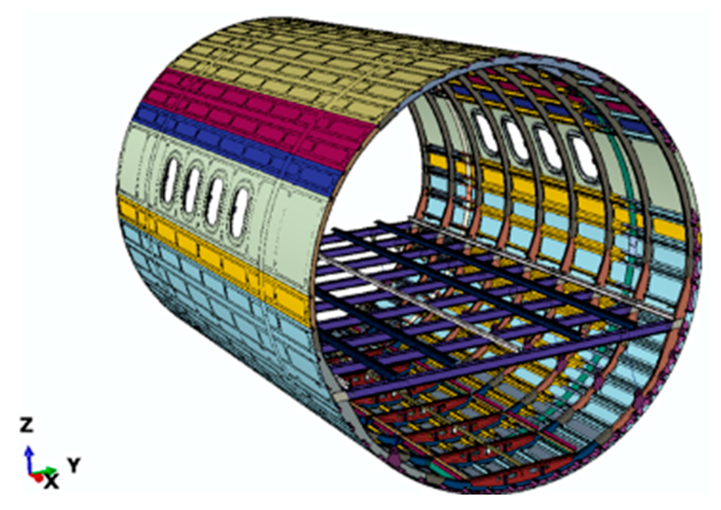
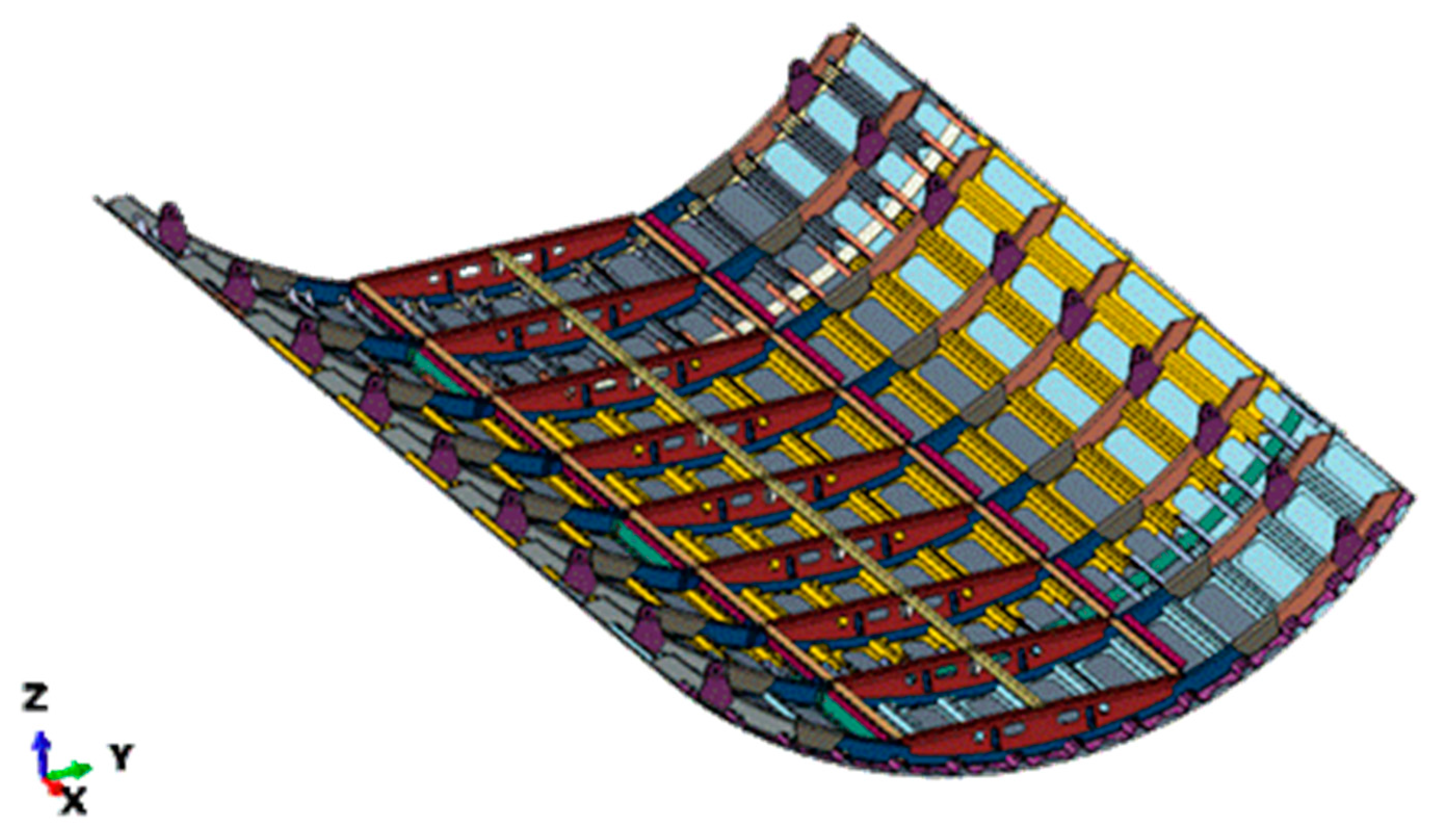
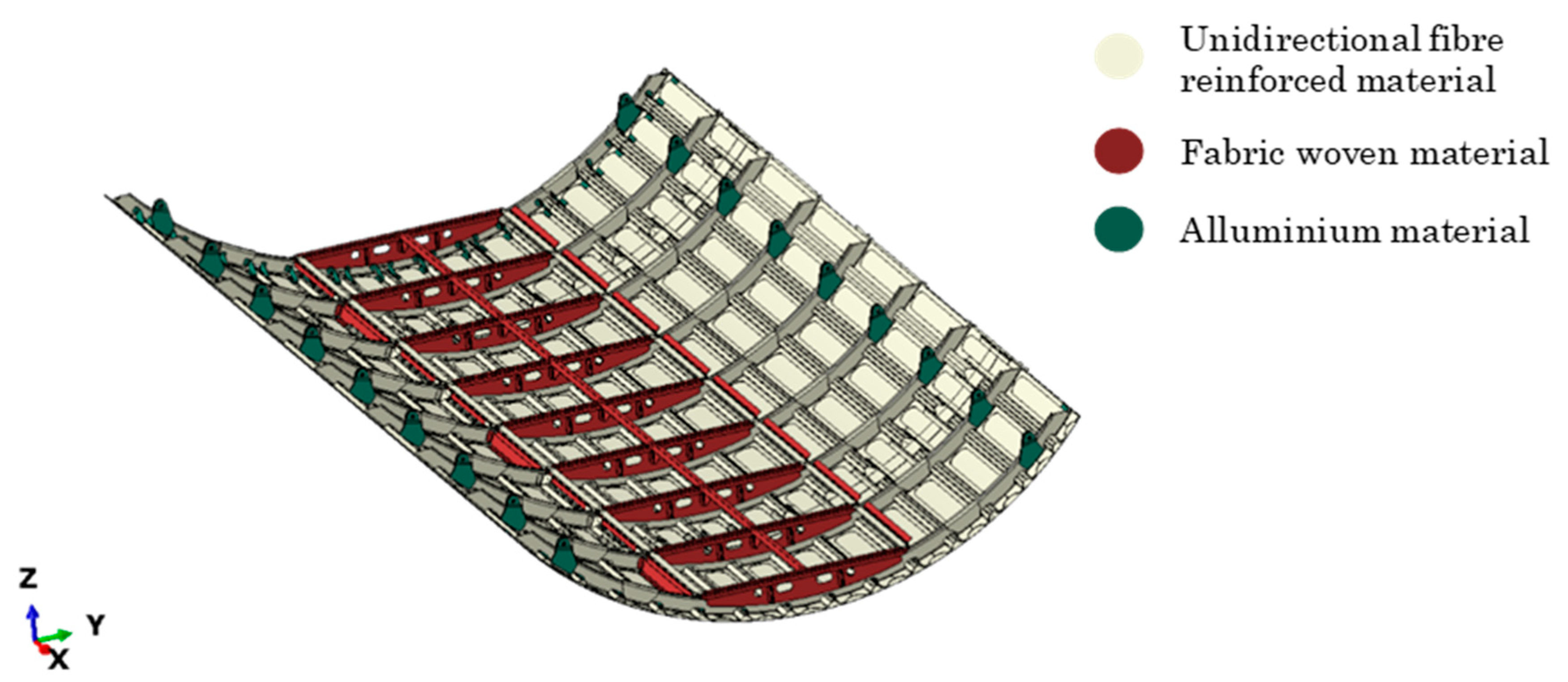
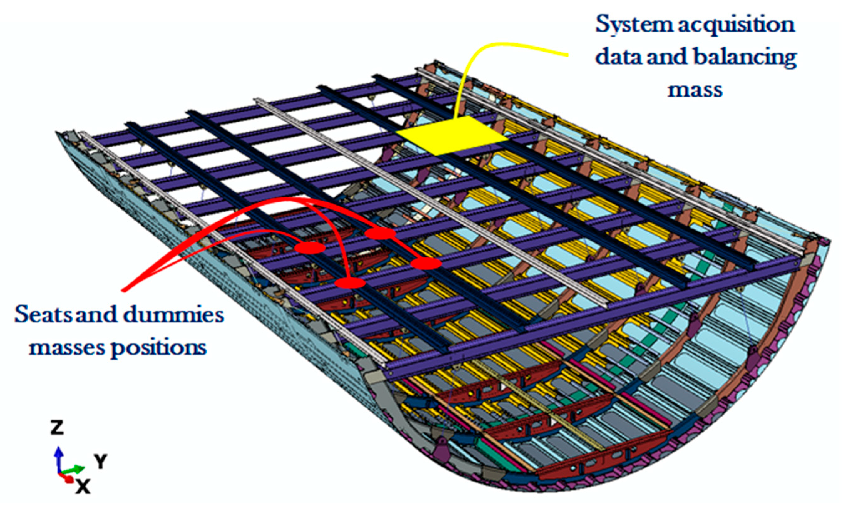
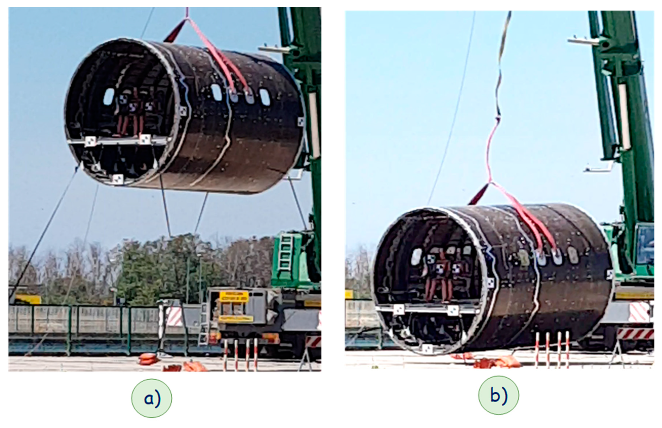
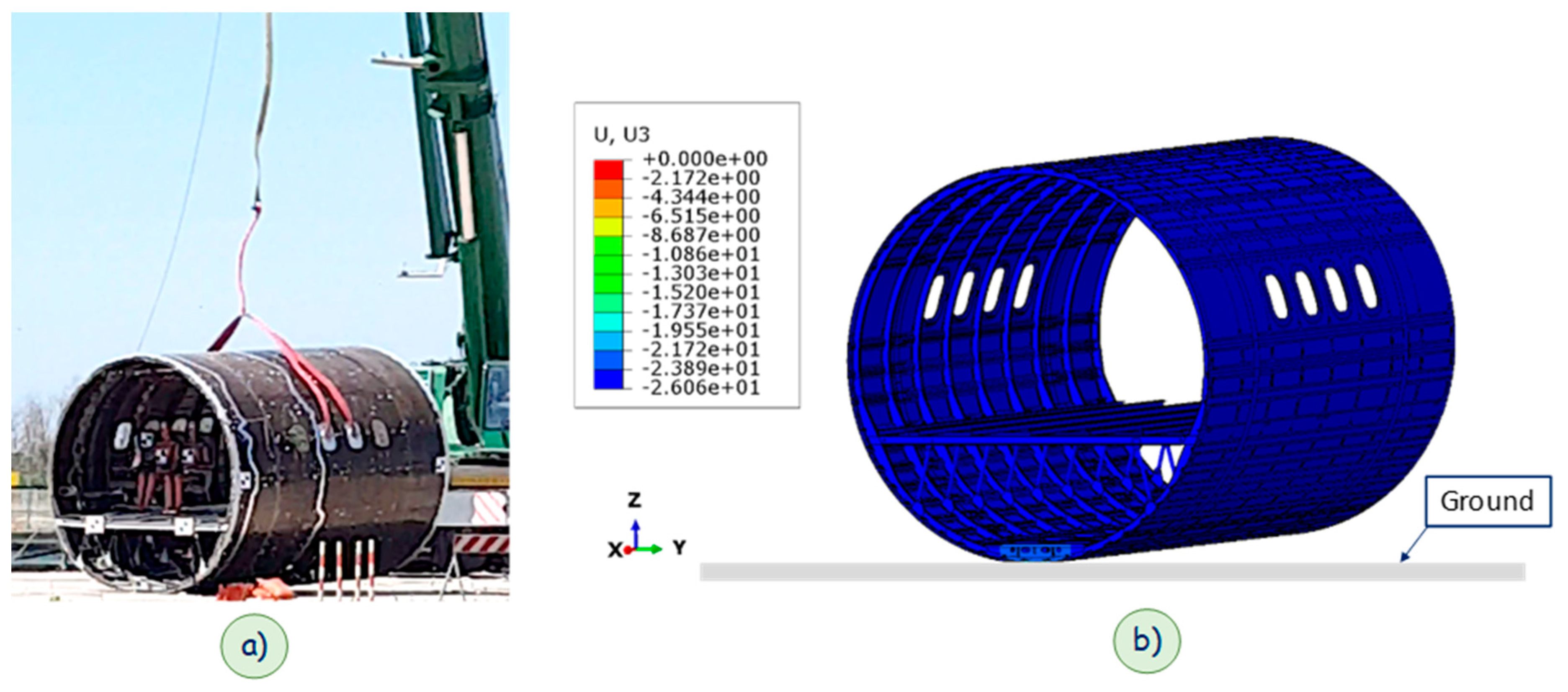
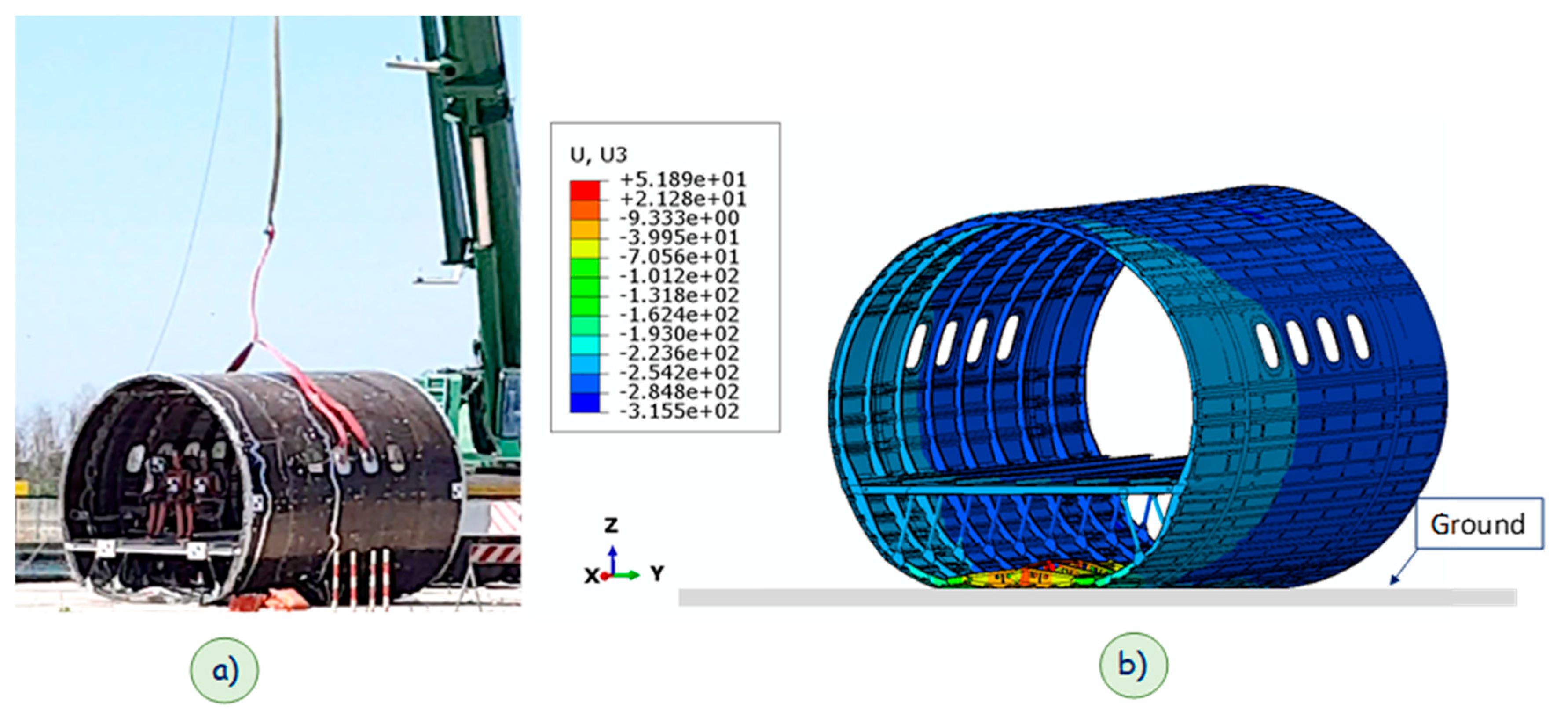
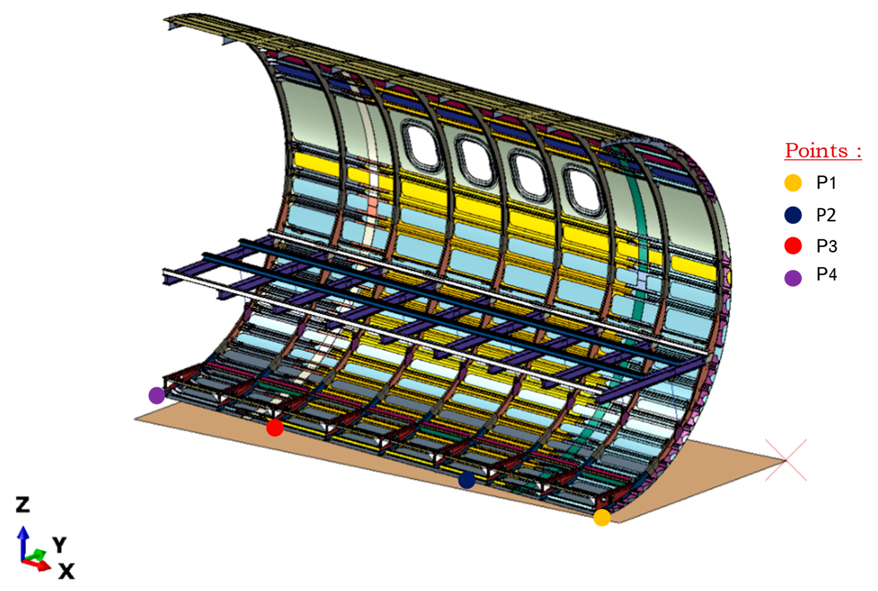
3. Geometrical Model and Numerical FEM Model Description
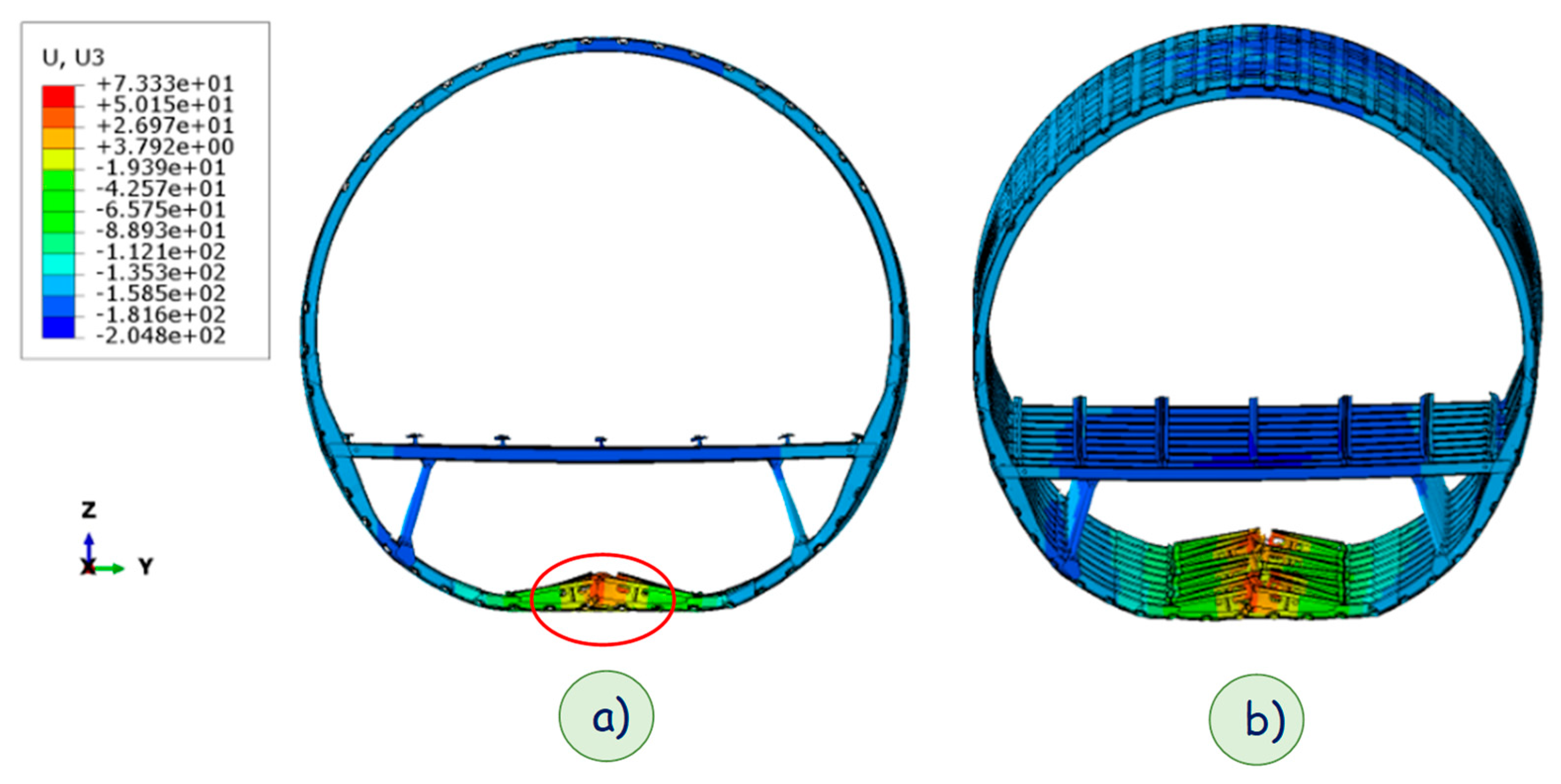
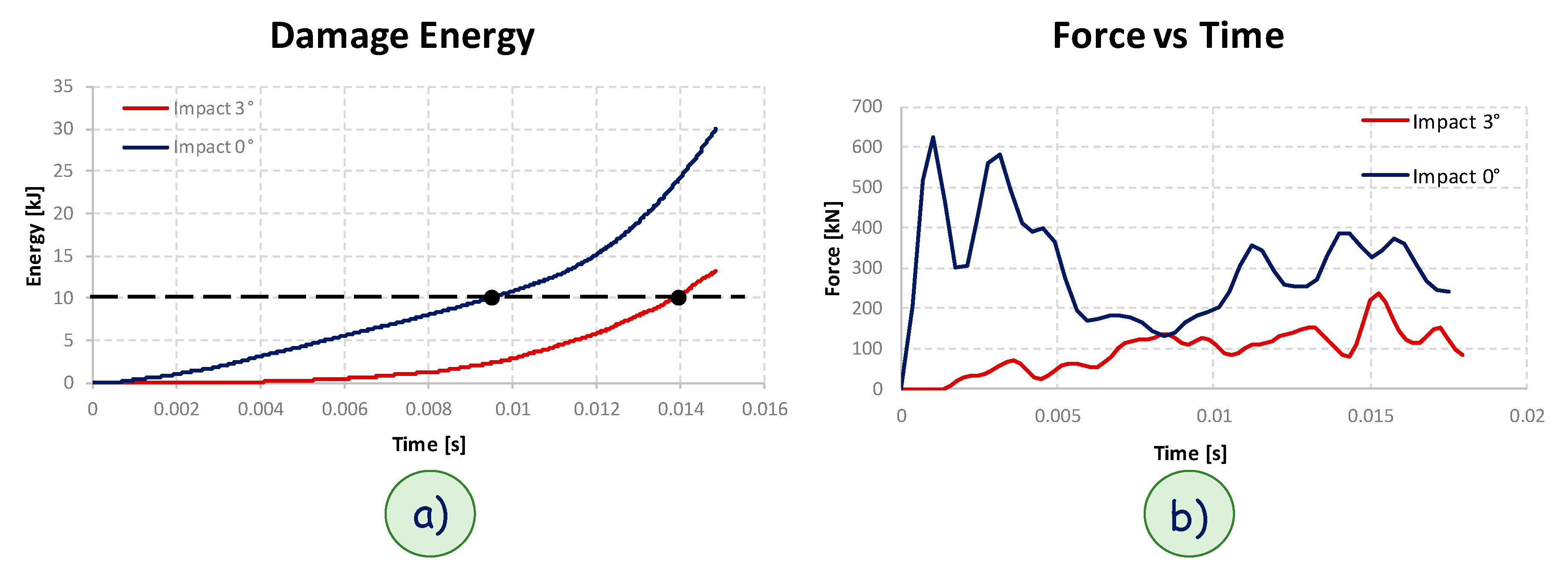
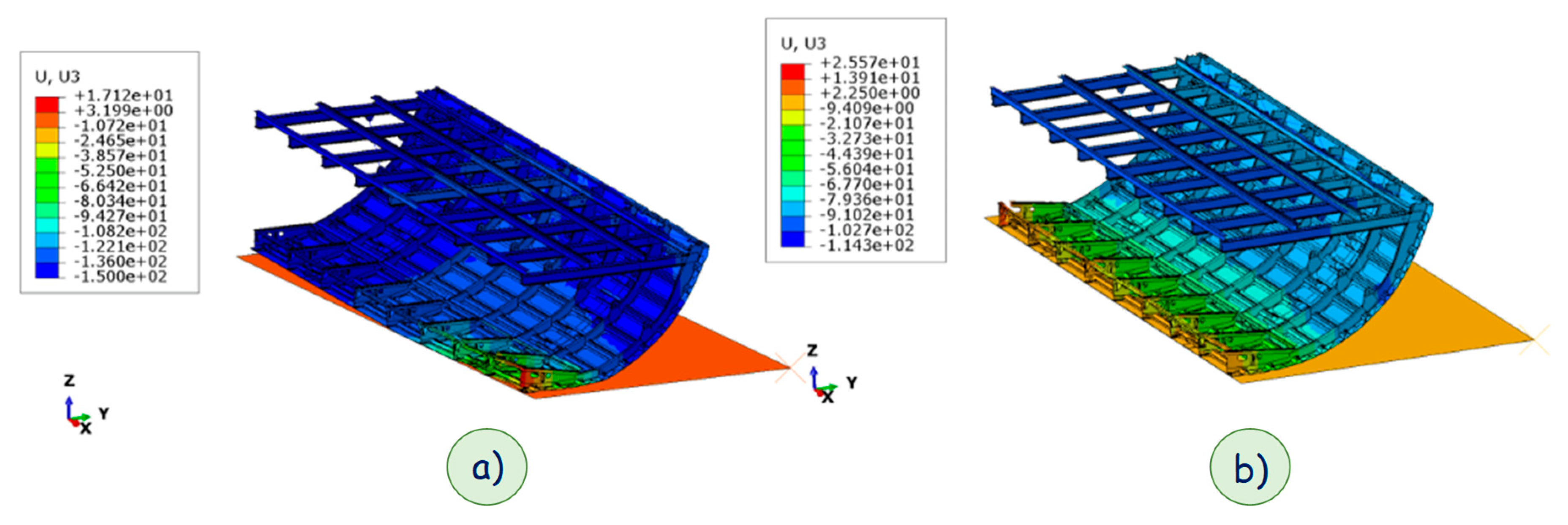
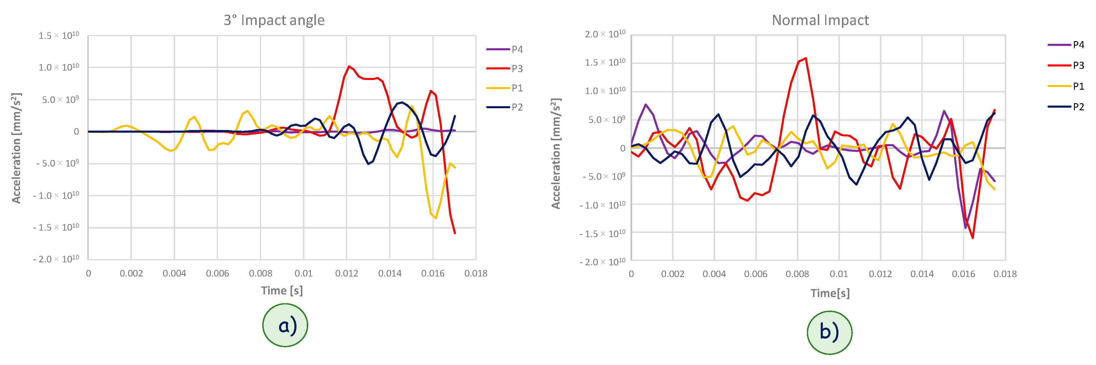
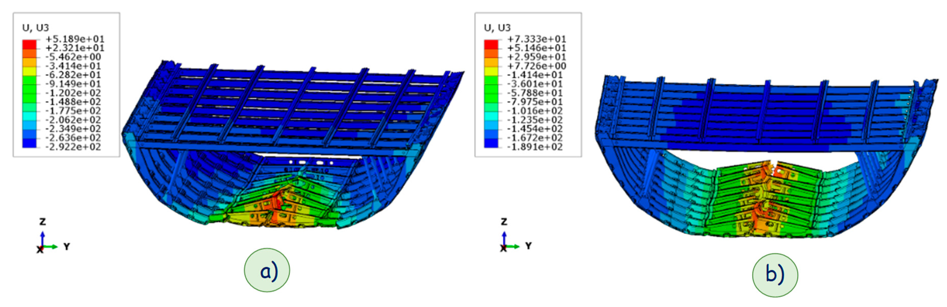
In this section, a brief description of the investigated fuselage section and general specifications of the adopted materials are provided, focusing on the sub-cargo area. Figure 2 shows the fuselage section with all subcomponents. The components with the same geometry and material have been grouped and reported with a different color. The considered fuselage section has a radius of 1811 mm and a length of 4926 mm.
The area of the fuselage most subjected to the kinetic energy absorption during the ground impact phenomenon is the sub-cargo floor area. Figure 3 shows the components of this section to better appreciate the design of this area.
Three different materials (unidirectional fiber-reinforced composite, woven fabric, and aluminum material) have been used to manufacture the sub-cargo area. The materials employed to manufacture the subcomponents are clearly identified in Figure 4.
The mechanical properties of the adopted material systems are reported in Table 2 (unidirectional Composite Fiber Reinforced Plastic—CFRP), Table 3 (woven fabric), and Table 4 (aluminum).
The whole fuselage section had a weight of 533.77 kg. Before the drop test, some additional masses were added, as shown in Figure 5: 185 kg were added due to the dummies and the seats; 186 kg due to both the data acquisition system and the balancing mass; and 22.80 kg due to the harnesses. In particular, the harness masses were composed of four steel beams with a square section area clamped on the four central windows with rigid support to avoid the window hole deformation.
Despite the masses fixed on the cabin floor were balanced respect to the pitch and roll axes, the fuselage section impacted the ground with a pitch angle of 3 degrees. Although a mass acting on a small area may cause local force intensification, this effect was assumed as almost negligible as a consequence of the masses locations and the cabin floor stiffness. Indeed, an approximate 940 kg weight for the section fuselage was achieved, by introducing ad hoc density values to obtain a total mass similar to the test distributed over the whole geometry to avoid imbalance. Two analyses were performed, considering firstly, a perpendicular impact between the ground and the fuselage section and further simulation with an approximate pitch angle of 3°. The whole model was composed of 1,976,157 nodes and 995,858 elements; the struts that connect the cabin floor to the cargo area were realized with beam section elements. The section beam had an internal radius of 18 mm and an external radius of 20 mm. The metal subcomponents were modeled with an eight-node three-dimensional element and a reduced integration scheme. The composite subcomponents were modeled with reduced integration scheme continuum shell elements according to the Abaqus/Explicit element library. The rigid plane was 4600 × 5500 mm2 dimensions in-plane and 1 mm out-of-plane. Furthermore, the plane was considered rigid to better simulate the ground effect and fixed in the space. On each node of the fuselage section, an initial velocity of 9900 mm/s was applied. This velocity was evaluated by considering a drop height of 5000 mm. The model was simplified by deleting physical connections, such as rivets and bolts and replacing their effect with a multipoint constrain tie available in Abaqus.

4. Results

The experimental test was performed at the Crash Laboratory owned by the Italian Aerospace Research Centre (CIRA) named “Laboratory for Impact testing of Structures in Aerospace field (LISA)”. The test article impacted the ground with a pitch angle of about 3°, as highlighted by Figure 6, where some frames of the drop test are shown. In particular, in Figure 6b the fuselage section pitch angle can be appreciated just before the impact with the ground. Therefore, in this section, numerical analyses are presented to assess the influence of the pitch angle on the damage behavior of the fuselage section. As a preliminary study, qualitative comparison in terms of failure onset and propagation between the experimental drop test and the numerical analyses has been reported. In this preliminary study, the numerical model has been validated by means of comparisons with the deformations arising from the experimental drop test.
Figure 7 shows the impact initiation between the fuselage section and the ground. Figure 7a shows the experiment test picture of the fuselage section touching the ground, while Figure 7b illustrates the numerical simulation considering a 3 degree sloped rigid plane. As highlighted in Figure 7, the unbalance of section fuselage led to impact initiation on a very small area.
Figure 8 compares the experimental test picture taken when the rear section of the fuselage section part touches the ground (Figure 8a) with the numerical simulation state in the same condition (Figure 8b). This image shows excellent agreement between the numerical model and the experimental test in terms of general subfloor deformation.
As already remarked, an additional numerical analysis simulating the impact between the fuselage section and the ground with no pitch angle was carried out. Deformations achieved during impact at the same time step needed the rear section of the real fuselage barrel to touch the ground during the experimental test (shown in Figure 9). According to Figure 9b, rather uniform damage on all the lower frames and reinforcements could be observed in the perpendicular impact between the rigid ground and the fuselage section.
Figure 10a summarizes the damage energy graphs for both configurations computed by the Abaqus code. The damage energies were evaluated as the sum of the dissipated damage energy (see Figure 1) of each element, for each failure mode. As can be observed from Figure 10a, the 10 kJ damage energy threshold (traced line in Figure 10a), was reached at different time steps by the two analyzed configurations. Indeed, the configuration with no impact angle reached the 10 kJ damage energy at about 9 ms, while the configuration with a 3° impact angle reached the 10 kJ damage energy at about 14 ms. These trends were expected, since the damaged area in the case of the perpendicular impact was much more extended, leading to a fast dissipation of energy as the fracture energy.
The graph in Figure 10b shows the trend of the force vs. time for the two analyzed configurations. The force was obtained as a reaction force on the rigid plane in the z-direction. For the zero-impact angle configuration, a maximum force value of about 200 kN was reached, while for the configuration with an impact angle of 3°, a maximum force value of about 150 kN was achieved. This behavior was representative of the deformations occurring to the two configurations. Indeed, the configuration undergoing the perpendicular impact experienced a more gradual deformation, being that the impact energy was distributed all along the whole fuselage length. Hence, the residual stiffness at the beginning of the impact event was still relevant, leading to a force peak, which could be appreciated in the force vs. time graph (Figure 10b). On the other hand, the fuselage impacting the ground with an angle of 3° experienced a sudden deformation on one edge, which caused a sudden degradation of the stiffness, leading to the absence of force peaks in the first stage of the impact event and, hence, as it could be observed in the force vs. time graph (Figure 10b).
Figure 11 shows the section of the deformed fuselage section evaluated, respectively, at 14 ms for the configuration with a 3° impact angle (Figure 11a) and 9 ms for the configuration with normal ground impact (Figure 11b). In these conditions, as it can be appreciated from Figure 10a, the same amount of fracture energy was dissipated (10 kJ energy). As already remarked, from the comparison between Figure 11a,b, it can be observed that the damaged area was much more extended in the configuration with the normal impact, if compared to the configuration with the impact at 3°.
From Figure 12, where a section of the impact fuselage section has been reported for the configuration with a 3° angle impact, four different nodes have been identified as control points for the accelerations. The same locations were taken as control point also in the fuselage model undergoing the perpendicular impact, in order to compare the effects of the impact angle on the acceleration distribution along the fuselage length.
In Figure 13, the acceleration along z-direction vs. time has been plotted at the control points locations (defined in Figure 12) for analysis of the two impact configurations. Indeed, Figure 13a reports the accelerations predicted for the 3° impact angle configuration, while Figure 13a reports the accelerations predicted for the perpendicular impact configuration. In the first stage of the impact event, the acceleration of the first control point (identified with a yellow point in Figure 12) in the case of the 3° impact angle (Figure 13a), was different from zero, while the other control points, not touching the ground, showed zero acceleration. This trend confirmed, for this configuration, that the impact force acted on a very small impact area at the beginning of the impact event. On the other hand, in the frame of the normal impact event, all the control points showed non-zero acceleration from the beginning. This trend confirmed, for this configuration, that as expected, the impact force acted all along the fuselage length from the beginning of the impact event.
Finally, a qualitative comparison between the two models is presented in Figure 14, where the lower region of the fuselage section in both the numerically simulated impact configurations (a 3° and perpendicular impact) are reported. In particular, Figure 14a shows the fuselage section with a 3° impact angle, while Figure 14b shows the fuselage section perpendicularly impacted on the ground.
In the case of a non-perpendicular impact with the rigid ground, considering the same amount of damage energy (see Figure 10a), the main amount of kinetic energy was absorbed only by the most external front frames and reinforcements. This caused more relevant deformations in this area, if compared to the perpendicular impact, where the damage in the sub-cargo area seemed to be almost uniformly distributed along the fuselage section length but concentrated in the central area of the subfloor with smaller deformations. The absorbed kinetic energy, dissipated by the structure in the form of fracture energy, seemed to produce more dangerous damage, which extended beyond the subfloor area and potentially affected in a more significant way the passenger area when a pitch angle was present.

5. Conclusions

In this paper, a numerical/experimental study on a composite fuselage section of a commercial aircraft was introduced. An advanced numerical model was presented, able to predict—in the initial phases—the behavior of the sub-cargo floor area when subjected to impact with the ground. In order to take into account the complex stress distribution, including shear stress, arising from the impact event, three-dimensional elements were used to discretize the finite element model. The numerical analyses were preliminarily correlated to experimental data from a drop test on a full-scale composite fuselage section in terms of deformation and failure onset and propagation. Then, numerical comparisons between a 3° pitch angle impact and a no pitch angle impact were presented, to understand the influence of the impact angle on the failure onset and evolution and on the safety of the passengers. The impact simulations with different impact angles demonstrated the criticality of crash events occurring with a pitch angle. As expected, the presence of the impact angle causes a kinetic energy absorption concentrated in a very small area of the structure, significantly increasing the deformations and leading to more severe and potentially more significant damage transmitted to the passenger area. The investigation of the effects of the impact angle on the passengers will be the focus of follow-on research.

Author Contributions

All the authors contributed equally to this work.

Funding

This research received no external funding.

Acknowledgments

The authors would like to acknowledge that part of the research activity, that provided the data adopted for this follow on research study described in the present paper, has been conducted within the frame of the research project PON03PE_00124 CERVIA (Metodi di Certificazione e Verifica Innovativi ed Avanzati) granted to DAC and funded by the M.I.U.R. The experimental drop test has been performed at the facility of the Italian Aerospace Research Centre (CIRA) located in Capua, Italy.

Conflicts of Interest

The authors declare no conflict of interest.

References

  1. Federal Aviation Regulations. Part 25—Aircrashworthiness Standards: Transport Category Airplanes; Federal Aviation Adminstration, Department of Transportation: Washington, DC, USA, 2003.
  2. Cronkhite, J.D.; Berry, V.L. Crashworthy Airframe Design Concepts—Fabrication and Testing; NASA Contractor, Report 3603; NASA: Washington, DC, USA, 1982.
  3. Guida, M.; Manzoni, A.; Zuppardi, A.; Caputo, F.; Marulo, F.; De Luca, A. Development of a multibody system for crashworthiness certification of aircraft seat. Multibody Syst. Dyn. 2018, 44, 191–221. [Google Scholar] [CrossRef]
  4. Caputo, F.; De Luca, A.; Marulo, F.; Guida, M.; Vitolo, B. Numerical-experimental assessment of a hybrid FE-MB model of an aircraft seat sled test. Int. J. Aerospace Eng. 2018, 8943826. [Google Scholar] [CrossRef]
  5. Riccio, A.; Caputo, F.; Di Felice, G.; Saputo, S.; Toscano, C.; Lopresto, V. A Joint Numerical-Experimental Study on Impact Induced Intra-laminar and Inter-laminar Damage in Laminated Composites. Appl. Compos. Mater. 2016, 23, 219–237. [Google Scholar] [CrossRef]
  6. Riccio, A.; Ricchiuto, R.; Saputo, S.; Raimondo, A.; Caputo, F.; Antonucci, V.; Lopresto, V. Impact behaviour of omega stiffened composite panels. Prog. Aerosp. Sci. 2016, 81, 41–48. [Google Scholar] [CrossRef]
  7. Ren, Y.R.; Xiang, J.W. Crashworthiness uncentainty analysis of typical civil aircraft based on Box-Behnken method. Chin. J. Aeronaut. 2014, 27, 253–262. [Google Scholar] [CrossRef]
  8. Caputo, F.; De Luca, A.; Greco, A.; Maietta, S.; Marro, A.; Apicella, A. Investigation on the static and dynamic structural behaviours of a regional aircraft main landing gear by a new numerical methodology. Frattura ed Integrità Strutturale 2018, 12, 191–204. [Google Scholar] [CrossRef]
  9. Riccio, A.; Cristiano, R.; Saputo, S.; Sellitto, A. Numerical methodologies for simulating bird-strike on composite wings. Compos. Struct. 2018, 202, 590–602. [Google Scholar] [CrossRef]
  10. Perfetto, D.; De Luca, A.; Lamanna, G.; Chiariello, A.; Di Caprio, F.; Di Palma, L.; Caputo, F. Drop test simulation and validation of a full composite fuselage section of a regional aircraft. Procedia Struct. Integr. 2018, 12, 380–391. [Google Scholar] [CrossRef]
  11. Jackson, K.E.; Fasanella, E.L. NASA Langley Research Center impact dynamics research facility research survey. J. Aircraft 2004, 41, 511–522. [Google Scholar] [CrossRef]
  12. Bisagni, C. Crashworthiness of helicopter subfloor structures. Int. J. Impact Eng. 2002, 27, 1067–1082. [Google Scholar] [CrossRef]
  13. Adams, A.; Lankarani, H.M. A modern aerospace modelling approach for evaluation of aircraft fuselage crashworthiness. Int. J. Crashworthiness 2003, 8, 401–413. [Google Scholar] [CrossRef]
  14. Sellitto, A.; Riccio, A.; Russo, A.; Zarrelli, M.; Toscano, C.; Lopresto, V. Compressive behaviour of a damaged omega stiffened panel: Damage detection and numerical analysis. Compos. Struct. 2019, 209, 300–316. [Google Scholar] [CrossRef]
  15. McGuire, R.J.; Nissley, W.J.; Newcomb, J.E. Vertical Drop Test of a Fairchild Metro III; FAA Report DOT/FAA/CT-93/1; U.S. G.P.O.: Washington, DC, USA, 1993.
  16. Abramowitz, A.; Ingraham, P.A.; McGuire, R. Vertical Drop Test of a Shorts 3-30 Airplane; FAA Report DOT/FAA/AR-99/87; U.S. G.P.O.: Washington, DC, USA, 1999.
  17. Federal Aviation Administration. Special Conditions: Boeing Model 787-8 Airplane; Crashworthiness, Docket No. NM368 Special Conditions No. 25-362-SC, US Federal Register 72; U.S. G.P.O.: Washington, DC, USA, 2007.
  18. Federal Aviation Administration. Special Conditions: Airbus A350-900 Airplane; Crashworthiness, Emergency Landing Conditions, Docket No. FAA-2013-0892 Special Conditions No. 25-537-SC, US Federal Register 79; U.S. G.P.O.: Washington, DC, USA, 2014.
  19. Maia, L.G.; de Oliveira, P.H.I.A. Crashworthy Composite Fuselage Section Concept for Next Generation General Aviation; SAE Technical Paper 2005-01-4011; SAE International: Warrendale, PA, USA, 2005. [Google Scholar]
  20. Riccio, A.; Raimondo, A.; Di Caprio, F.; Fusco, M.; Sanità, P. Experimental and numerical investigation on the crashworthiness of a composite fuselage subfloor support system. Compos. Part B Eng. 2018, 150, 93–103. [Google Scholar] [CrossRef]
  21. Kumakura, I.; Minegishi, M.; Iwasaki, K. Impact Simulation of Simplified Structural Models of Aircraft Fuselage; SAE Technical Paper 2000-01-5586; SAE International: Warrendale, PA, USA, 2000. [Google Scholar]
  22. Zheng, J.; Xiang, J.; Luo, Z.; Ren, Y. Crashworthiness design of transport aircraft subfloor using polymer foams. Int. J. Crashworthiness 2011, 16, 375–383. [Google Scholar] [CrossRef]
  23. Shoji, H.; Miyaki, H.; Iwasaki, K.; Minegishi, M. Crashworthiness research on cabin structure at JAXA. In Proceedings of the 5th Triennial International Aircraft Fire and Cabin Safety Research Conference, Atlantic City, NJ, USA, 30 October 2007. [Google Scholar]
  24. Ren, Y.; Xiang, J. A comparative study of the crashworthiness of civil aircraft with different strut configurations. Int. J. Crashworthiness 2010, 15, 321–330. [Google Scholar] [CrossRef]
  25. Hu, D.Y.; Meng, K.P.; Yang, Z.Y. Numerical investigation of the energy absorption characteristics of a fan shaped deployable energy absorber. Int. J. Crashworthiness 2014, 19, 126–138. [Google Scholar] [CrossRef]
  26. Huculak, R.D.; Lankarani, H.M. Methods of evaluating ES-2 leg flail in dynamic evaluation and certification tests of side-facing aircraft seats. Int. J. Crashworthiness 2015, 20, 613–628. [Google Scholar] [CrossRef]
  27. Liu, X.C.; Guo, J.; Bai, C.Y.; Sun, X.S.; Mou, R.K. Droptest and crash simulation of a civil airplane fuselage section. Chin. J. Aeronaut. 2015, 28, 447–456. [Google Scholar] [CrossRef]
  28. Paz, J.; Diaz, J.; Romera, L.; Costas, M. Size and shape optimization of aluminum tubes with GFRP honeycomb reinforcements for crashworthy aircraft structures. Compos. Struct. 2015, 133, 499–507. [Google Scholar] [CrossRef] [Green Version]
  29. Ren, Y.R.; Xiang, J.W. The crashworthiness of civil air Craft using different quadrangular tubes as cabin-floor struts. Int. J. Crashworthiness 2011, 16, 253–262. [Google Scholar] [CrossRef]
  30. Ren, Y.R.; Xiang, J.W. Energy absorption structures design of civil aircraft to improve crashworthiness. Aeronaut. J. 2014, 118, 383–398. [Google Scholar] [CrossRef]
  31. Ren, Y.R.; Xiang, J.W.; Zheng, J.Q.; Luo, Z.P. Crashworthiness analysis of aircraft fuselage with sine-wave beamstructure. Chin. J. Aeronaut. 2016, 29, 403–410. [Google Scholar] [CrossRef]
  32. Schatrow, P.; Waimer, M. Crash concept for composite transport aircraft using mainly tensile and compressive absorption mechanisms. CEAS Aeronaut. J. 2016, 7, 471–482. [Google Scholar] [CrossRef]
  33. Shi, Q.H.; Dai, D.; Cao, Z.H. Tensile failure strength analysis and Experimental confirmation of stitch reinforced composite of T-stiffened structure. Polym. Compos. 2012, 20, 307–311. [Google Scholar] [CrossRef]
  34. Sturma, R.; Klett, Y.; Kindervater, C.; Voggenreiter, H. Failure of CFRP airframe sandwich panels under crash relevant loading conditions. Compos. Struct. 2014, 112, 11–21. [Google Scholar] [CrossRef]
  35. Riccio, A.; Raimondo, A.; Saputo, S.; Sellitto, A.; Battaglia, M.; Petrone, G. A numerical study on the impact behaviour of natural fibres made honeycomb cores. Compos. Struct. 2018, 202, 909–916. [Google Scholar] [CrossRef]
  36. Khalili, S.M.R.; Soroush, M.; Davar, A.; Rahmani, O. Finite element modeling of low-velocity impact on laminated composite plates and cylindrical shells. Compos. Struct. 2011, 93, 1363–1375. [Google Scholar] [CrossRef]
  37. Chattopadhyay, S. Response of elastic plates to impact including the effects of shear deformation. In Recent Advances in Engineering Science; Springer: Berlin, Germany, 1977; pp. 127–138. [Google Scholar]
  38. Shivakumar, K.N.; Elber, W.; Illg, W. Prediction of impact force and duration due to low-velocity impact on circular composite laminates. J. Appl. Mech. Trans. ASME 1985, 52, 674–680. [Google Scholar] [CrossRef]
  39. Dassault System Abaqus 2016 User’s Manual; Dassault Systèmes Simulia Corp.: Providence, RI, USA, 2016.
Figure 1. Constitutive relation (damage evolution).
Aerospace 06 00072 g001
Figure 2. Whole fuselage section.
Aerospace 06 00072 g002
Figure 3. Subsection cargo floor.
Aerospace 06 00072 g003
Figure 4. Sub-cargo components and materials.
Aerospace 06 00072 g004
Figure 5. Position of seat dummies and added masses balancing.
Aerospace 06 00072 g005
Figure 6. Fuselage section drop test: (a) Before the drop test; (b) during the fall.
Aerospace 06 00072 g006
Figure 7. First phase of the fuselage section impact with ground: (a) Experimental test; (b) numerical simulation (units in mm).
Aerospace 06 00072 g007
Figure 8. Frame of the fuselage section impact with ground: (a) Experimental test; (b) numerical simulation (units in mm).
Aerospace 06 00072 g008
Figure 9. Fuselage section impact parallel to the ground: (a) Frontal view; (b) rotated view (units in mm).
Aerospace 06 00072 g009
Figure 10. (a) Damage energy graph; (b) force vs. time graph.
Aerospace 06 00072 g010
Figure 11. Initial phases of sub-cargo area impact: (a) 3° impact angle; (b) normal angle (units in mm).
Aerospace 06 00072 g011
Figure 12. Node positions.
Aerospace 06 00072 g012
Figure 13. Acceleration of four different points: (a) 3° impact angle; (b) normal impact.
Aerospace 06 00072 g013
Figure 14. Sub cargo area: (a) Sloped impact; (b) normal impact (units in mm).
Aerospace 06 00072 g014
Table 1. Equivalent stress and displacement definitions.
FailureEquivalent StressEquivalent Displacement
Fiber tension L c ( σ 11 ε 11 + σ 12 ε 12 ) δ f t , e q L c ε 11 2 + ε 12 2
Fiber compression L c σ 11 ε 11 δ f c , e q L c ε 11
Matrix tension L c ( σ 22 ε 22 + σ 12 ε 12 ) δ m t , e q L c ε 22 2 + ε 12 2
Matrix compression L c ( σ 22 ε 22 + σ 12 ε 12 ) δ m c , e q L c ε 22 2 + ε 12 2
where LC and < > are, respectively, the element characteristic length and the Macauley bracket operator [39].
Table 2. Unidirectional fiber composite material mechanical properties.
Unidirectional CFRP
Young’s Modulus, E11 [MPa]137,500
Young’s Modulus, E22 [MPa]8200
Shear Modulus, G12 [MPa]3950
Shear Modulus, G13 [MPa]3950
Shear Modulus, G23 [MPa]3950
Poisson’s ratio, ν12 = ν13 = ν23 [-]0.35
Fiber Tensile Strength, F1t [MPa]1890
Fiber Compressive Strength, F1c [MPa]1008
Matrix Tensile Strength, F2t [MPa]86.5
Matrix Compressive Strength, F2c [MPa]112
In-Plane Shear Strength, S12 [MPa]95
Out-Plane Shear Strength, S23 [MPa]100
Density, ρ [ton/mm3]1.9 × 10−9
Ply thickness, tp [mm]0.129
Table 3. Woven fabric material mechanical properties.
Woven Fabric
Young’s Modulus, E11 [MPa]55,000
Young’s Modulus, E22 [MPa]55,000
Shear Modulus, G12 [MPa]3363
Shear Modulus, G13 [MPa]3363
Shear Modulus, G23 [MPa]3363
Poisson’s ratio, ν12 = ν13 = ν23 [-]0.30
Fiber Tensile Strength, F1t [MPa]650
Fiber Compressive Strength, F1c [MPa]650
Matrix Tensile Strength, F2t [MPa]650
Matrix Compressive Strength, F2c [MPa]650
In-Plane Shear Strength, S12 [MPa]150
Out-Plane Shear Strength, S23 [MPa]150
Density, ρ [ton/mm3]1.97 × 10−9
Ply thickness, tp [mm]0.25 mm
Table 4. Aluminum Al2024 mechanical properties.
Al2024
Young’s Modulus, E [MPa]70,000
Poisson’s ratio, ν [-]0.33
Yield stress, σy [MPa]369
Ultimate Tensile stress, σf [MPa]469
Density, ρ [ton/mm3]2.7 × 10−9

