Article

Optimization of the Energy Storage of Series-Hybrid Propelled Aircraft by Means of Integer Differential Evolution

by
Liviu Sevastian Bocii
1,†,
Luigi Pio Di Noia
2,† and
Renato Rizzo
2,*,†
1
Department of Automation, Industrial, Textile and Transportation Engineering, Aurel Vlaicu University of Arad, 310130 Arad, Romania
2
Department of Electrical Engineering and Information Technologies, University of Naples Federico II, 80125 Naples, Italy
*
Author to whom correspondence should be addressed.
These authors contributed equally to this work.
Aerospace 2019, 6(5), 59; https://doi.org/10.3390/aerospace6050059
Submission received: 4 February 2019 / Revised: 8 March 2019 / Accepted: 22 March 2019 / Published: 23 May 2019

Abstract

:
The possibility of realizing full electric or hybrid electric propulsion for aircraft has been considered due to the constant growth in the use of electric technologies in aircraft and the availability of high-power-density electrical machines and converters. In this paper, an optimized design approach is proposed with reference to the optimal trade-off between energy storage system sizing and the fuel mass of a series of hybrid aircraft. The problem is approached using an integer optimization algorithm based on differential evolution and by mixing both the flight mechanics and the electrical issues inherent to hybrid flights. This method has been validated by means of implementing numerical simulations and the results are reported and discussed in the paper.

1. Introduction

In the last two decades, increasing interest regarding the More Electric Aircraft (MEA) concept has been generated [1] with the aim of reducing fuel consumption, reducing emissions released into the atmosphere, increasing the redundancy and the reliability of onboard power systems, and reducing aircraft noise.
Recently, several research projects have led to the substantial electrification of onboard pneumatic components in order to increase the efficiency of flight systems—which has also introduced redundancies across the subsystems [2]—and the necessity to propose new power system architectures for the reduction of weight, increase of the reliability and to assure the correct performance of electrical drives [3]. Moreover, in order to increase the reliability and decrease the weight, DC-microgrids [4] seem to be the most suitable solution for future aircraft.
The current trend also envisages the use of electrical technology in aircraft propulsion [5,6,7,8] and both fully electric and hybrid propulsion aircraft prototypes have been presented. In the all-electric propulsion concept, the fuel and the thermal engine are completely substituted with energy storage systems (above all, fuel cells and battery) that are able to provide the entirety of the electric power required by the aircraft. The use of these new energy systems on board aircraft has been analyzed widely in the literature. In [9], an aircraft design that relies on fuel cells for propulsion and that is characterized by an unusual motor placement in order to maximize efficiency is presented, while in reference [10], the behavior of batteries that are used for the propulsion of small unmanned aircraft vehicles (UAV) at different temperatures is discussed. Additionally, Tariq [11] presents an overview of the battery systems for the MEA with an analysis of battery management systems for Li-ion batteries. Hybrid propulsion [12,13,14,
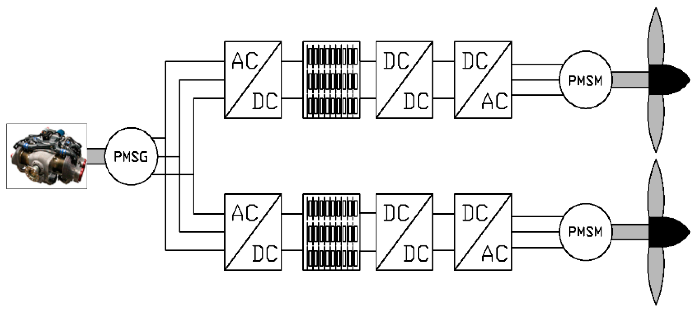
15] is quite similar to the hybrid traction used in automotive applications; the propulsion can be achieved with the use of electric motors or with both electric motors and internal combustion engines (ICEs). The electric power is provided by ICEs coupled with an electric generator and usually from a battery pack; the possible series and parallel configurations are similar to the scheme used in the automotive industry [16,17]. In this paper, the approach used was applied to an existing aircraft and the “electrification” of propulsion was made without any change to the aircraft structures, the maximum take-off weight, or the aerodynamic performance. The possibility of changing the complete structure of the aircraft surely permits an increase in the performance and convenience of hybrid propulsion [18].
The sizing of electrical energy storage systems is a critical issue for their integration in aircraft and its optimization is mandatory. Different sizing tools for supercapacitor or battery systems are suggested in [19,20]. In these tools, only one storage system is sized at a time and with one pre-chosen cell.
Novel approaches based on optimization algorithms—so-called integrated design by optimization—are becoming increasingly mature and will become particularly powerful if subsequent efforts are made in terms of modeling for design.
The integrated optimal design approach consists of coupling sizing models with an optimization algorithm that automatically tunes the parameters to optimize system criteria (mass, losses, etc.) while satisfying the technological and operational constraints.
Many types of optimization procedures can be utilized in engineering applications: single or multi-objective, continuous or discrete optimization, linear or non-linear optimization, non-gradient optimization techniques, etc. The choice of the type of optimization is related to specific mathematical problems and to the technical boundary conditions (e.g., the necessity of using integer variables). Regarding the considered problems, as mentioned above, the necessity of reducing pollution requires the determination of an optimal trade-off problem between the size of the onboard energy storage system and the mass of the fuel. The objective functions can be different, as proposed in the literature (e.g., [21]). The problem is solved by the optimization of three different objective functions related to the energy cost, which is the primary energy required in order to guarantee flight completion and the reduction of CO2 emissions. In [22], the size of the hybrid storage system which is constituted by supercapacitors and batteries is optimized and the objective function is inherent to the reduction of the total mass of the primary energy. In [13], a simple conceptual design approach is proposed to determine the optimal size of the battery system in order to maximize the range or duration of the flight for the available fuel in the aircraft’s tank. In [22,23], a sizing tool for reducing the global storage system’s weight by taking several constraints (environmental and electrical ones) into account and by adjusting some parameters—such as the discharge ratio of the storage components and the ambient temperature—within a proper energy management strategy was proposed. The sizing method was improved upon with an optimization algorithm solved by a simulated annealing method. In [24], a sizing methodology for the battery of an UAV is proposed. The methodology is based on the use of an integral formulation for the constant discharge of battery power, thereby obtaining the optimal size of the batteries.
In this paper, an integer optimization procedure is proposed, which permits the integer character of some variables and the simultaneous solution to both the mechanical flight problem and electrical problem related to the energy storage systems to be taken into account. Regarding the mechanical flight problem, a mathematical approach that is able to solve the mechanical flights equation during the climb phase, based on the energy minimization is proposed. The solution of the optimization procedure is mainly based on the use of an integer differential evolution approach (IDEA) [25]. The differential evolution is a simple and efficient algorithm which permits the solution of the optimization problem with a rapid convergence to the solution. The need to use an integer optimization is due to the nature of the battery packs, where the number of cells or modules are integer numbers. In the literature [20,24,26], it is typically found that the battery storage systems are of optimal size in terms of both energy and power; therefore, the determination of the number of cells is postponed; in this way, it is guaranteed that the optimal value of the energy and power is achieved, but it is not guaranteed that the number of cells is optimal.
Starting from an assigned flight profile (cruise altitude, cruise speed, cruise range), the aim of this paper is to develop an optimization procedure which can be used during the pre-flight settings and is able to evaluate the optimal integration of the battery storage system and ICE to guarantee the correct operation during the execution of the flight profile.
The main novelty of the proposed optimization procedure regards the possibility to use it as a pre-mission energy management process. In fact, with the possibility to develop a modular battery pack and considering the mission profile, it is possible to calculate the optimal size of the battery pack. Through a new disposition of the module of the pack (each module can be constituted by a certain number of parallel and series cells), it is possible to minimize and reduce the useless weight of the aircraft.
The optimized design approach of the sizing of the energy storage system of a series-hybrid aircraft is detailed and validated in this paper. In the next section, the hybrid propulsion system of the aircraft is defined. In the third section, the dynamic equations of the aircraft profile are detailed and in Section 4 the battery system model is explained. The optimization sizing procedure is proposed in Section 5 and validated by simulation in Section 6 where the results are reported and discussed.

2. Hybrid Propulsion Scheme

A series-hybrid propulsion scheme is considered in the present work. The advantages of a series-hybrid propulsion are different, for example, the thermal engine can be controlled to let it operate at a fixed point during the recharging of the batteries, with the possibility to keep constant and maximize the efficiency. Furthermore, the series propulsion provides the possibility of having only electric propulsion of the propellers, avoiding the mechanical gear between the engine and the propeller, and increasing the efficiency (in particular when the propellers have a fixed pitch, and in this case, the variation of the speed within a certain range is necessary). Figure 1 shows a scheme of the series-hybrid architecture considered in the paper.
The architecture is based on a twin-propeller civil aircraft. Each propeller is controlled by a permanent magnet synchronous motor (to increase the reliability, it is also possible to use a motor with more than three phases), a cascade of a DC-DC converter, and a VSI links the battery modules to the motor. A single energy storage system and a single controlled rectifier for both the propellers are considered in the scheme. The reliability of the system can be increased by dividing the battery pack into two parts and using two different rectifiers (Figure 2). In this way, the propulsion system is not completely compromised when a fault occurs in either the storage system or in one of the converters.

3. Dynamics Equations of Aircraft Load Profile

To determine the dimension of the batteries and AVGAS, which must be used for the aircraft flight, it is necessary to model the aircraft trajectories, which can be divided into take-off, climb, cruise, and landing. The energy management strategy considered in this paper is based on the use of an all-electric propulsion during the take-off and climb phases and a mixed electric and series-hybrid propulsion during the cruise. The use of full electric propulsion during the take-off and the climb reduces the noise and pollution emissions of the aircraft, in particular when the aircraft is near the airport and the city; therefore, it is considered a so-called “green” integration of the airport in the city. The sizing of the battery and the determination of the fuel weight depend on the trajectories of the aircraft and their values’ influence the performance of the aircraft. The modeling of the aircraft profile can be done using the equation of dynamics.

3.1. Take-Off Dynamics Equation

During the take-off, two different types of forces act upon the aircraft: the friction forces due to the weight of the aircraft and the contact between the tires and the ground and the aerodynamic drag. Considering Equations (A1)–(A3) in Appendix A, it is possible to determine the length of the take-off using the following equation:
x t o = W ρ g S ( C d μ C l ) log [ ( T μ W 1 , 44 ( C d μ C l ) C l , max ) ( T μ W ) ]
During the take-off, it is assumed that the propulsion happens with a constant power equal to the maximum power of the propulsion system.

3.2. Climb Phase Dynamics Equation

Considering that the trust vector is parallel to the climb trajectory, the variation of the climb angle during the flight is negligible, and taking into account the dynamic Equation (A4), the duration of the climb [22] can be calculated by integrating the following equations:
d t d h = 1 P s ( v g d v d h + 1 )
where PS is equal to:
P s = v ( T D ) W
and defines the specific excess power. The equations of Equation (A4) are referred to an ascendant climb phase and can also be considered for the descendent climb, with a variation of the signs in the equilibrium of the dynamic quantities.

3.3. Cruise Phase

The cruise phase is modeled supposing that the speed cruise and the altitude are kept constant; taking into account that during the cruise, the propulsion is electric but the energy is provided both by the batteries and the fuel. Starting from Equation (A5) and using some manipulations of the formula, it is possible to determine the Breguet range [27] equation, which depends on the initial and final value of the weight of the aircraft and also, on the fuel consumption:
x c = η p H g C l C d log ( W W f )
with ηp equal to the product of thermal engine efficiency, propeller efficiency, electric generator and motor efficiency, battery conversion efficiency, and converter efficiency.

4. Modeling of the Electrical Storage System

The sizing of the energy storage system and the determination of the fuel mass necessary for the optimal thermal engine performance can be done by means of models of the electric components of the propulsion system. The electric motor and power converter can be modeled considering only the power density (kW/kg) and the efficiency, which depend on the load. The power densities of the electrical machines and converters are calculated considering the data of commercially available three-phase permanent magnet machines and converters with a high power density (all of the considered components are liquid cooled), the efficiency is modeled using a polynomial which depends on the required load power and is obtained from the datasheet of the commercial components.

Battery Modeling

The battery storage system is modeled according to [26]:
{ V o c , s m = c 0   S o C ( t ) + c 1 I b , m ( t ) n p [ n s V o c , s m R b I b , m ( t ) ] = P e l e S o C ( t ) = S o C ( t 0 ) 1 Q b t 0 t f I b , m ( t ) d t
where the meaning of the utilized symbols can be found in Figure 3. ns indicates the number of series cells, while np is the number of parallel branches. The current of a single cell is Ib,m; the sum of the currents of each branch gives the total current of the battery pack. Without any current, the output voltage is Voc,sm (due to the internal voltage drop, this value decreases when the battery is not zero).
It is assumed that the battery temperature is kept constant (the variation of temperature could be due to the variation in the ambient temperature at different altitudes or to the losses generated during the operations). With this assumption, it is possible to avoid the dependence of battery parameters on the variable temperature, with a reduction of the complexity of the problem.

5. Optimization Procedure

The optimization procedure is mainly based on the use of an integer differential evolution approach (IDEA) [
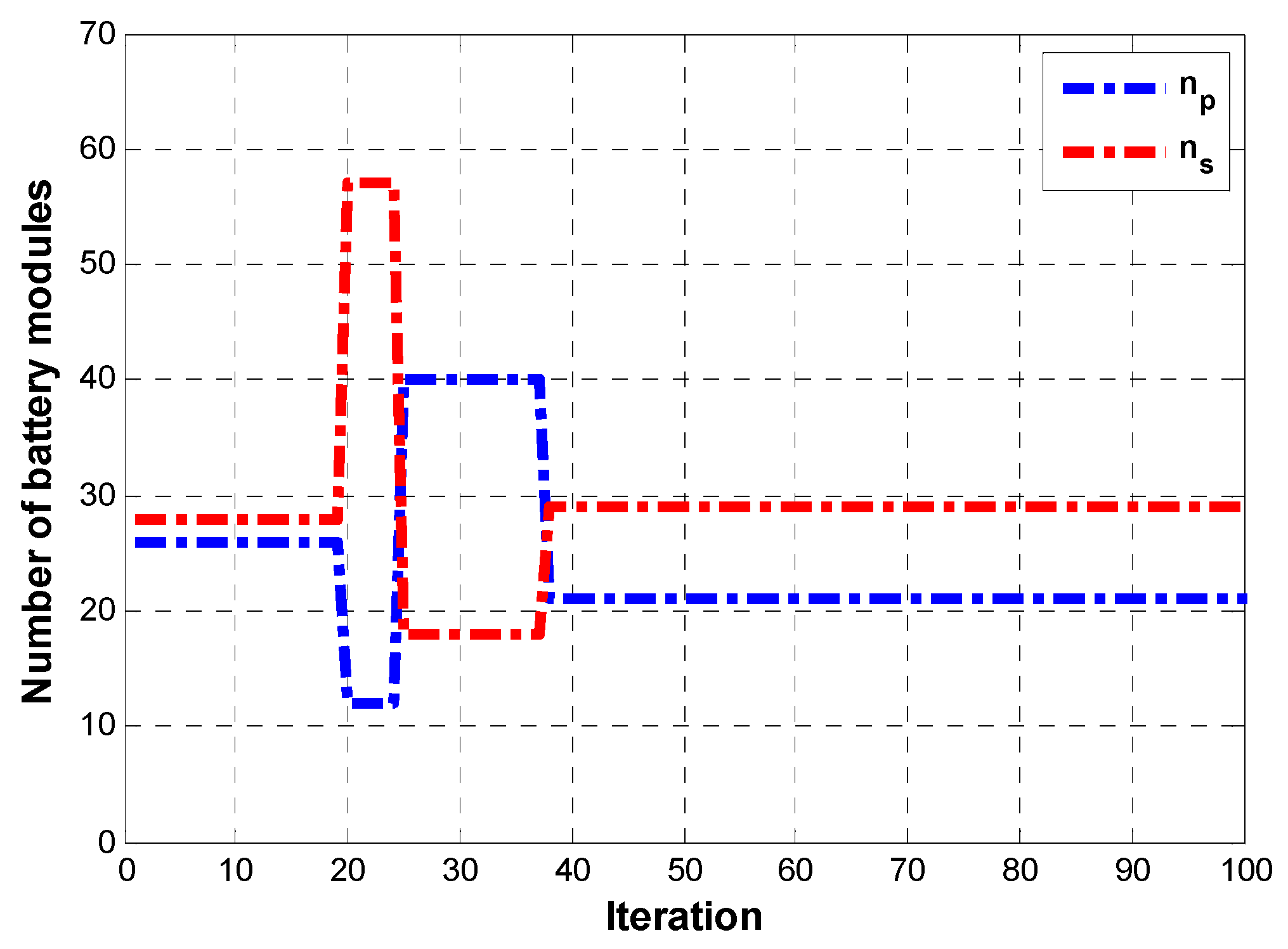
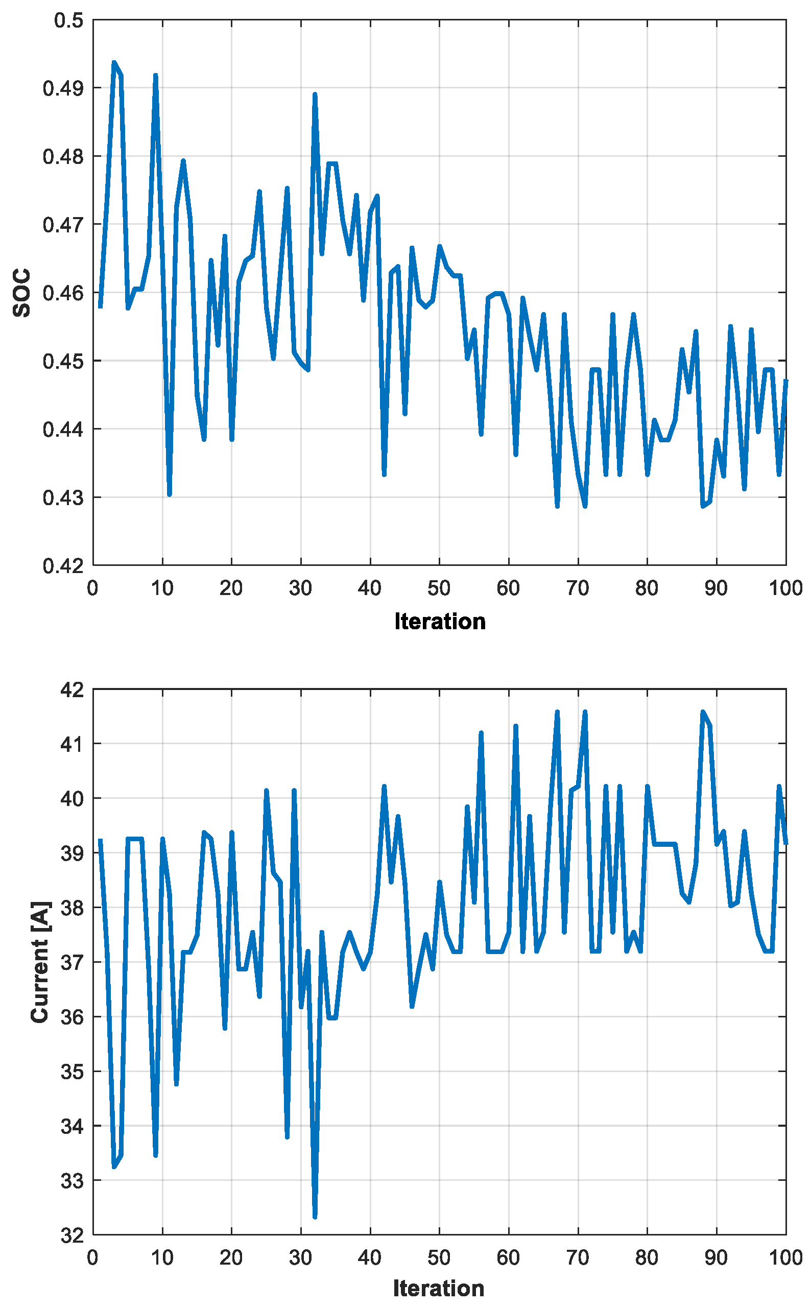
21] with the aim to minimize (or maximize) certain parameters of the aircraft or the physical parameters of the aircraft trajectories. The optimization procedure is realized on more levels; the external level is inherent to the IDEA technique and acts on three variables: the number of parallel cells np and series cells ns, and the weight of fuel. At each iteration of the optimization, the procedure solves another three problems linked to the optimization of the trajectories. 
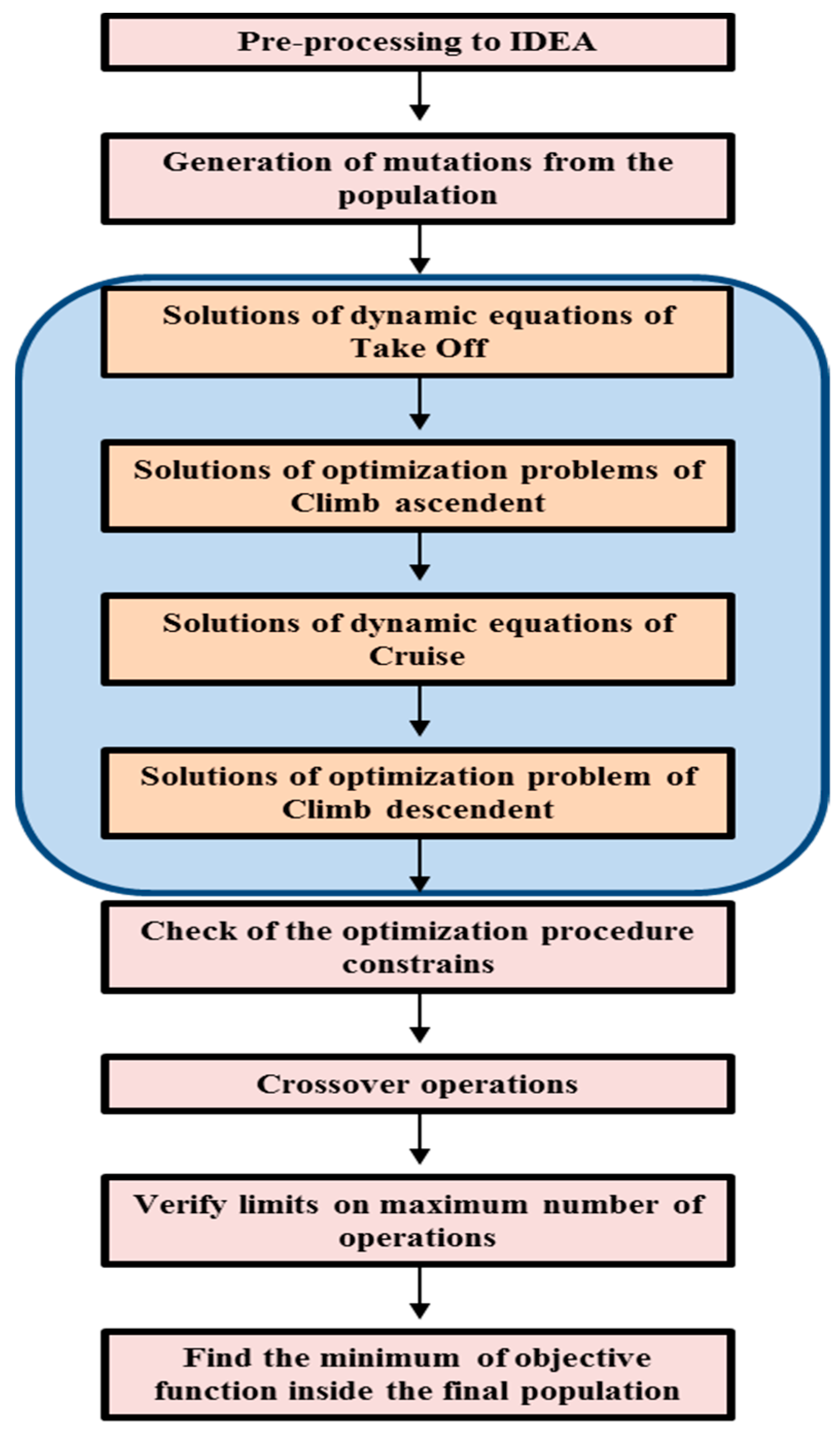
Figure 4 shows a flowchart of the procedure.

5.1. Pre-Processing to IDEA

Before initializing the procedure, a population of npop possible solutions is generated:
x pop = [ n p , 1 n s , 1 m f u e l , 1 n p , 2 n s , 2 m f u e l , 2 n p , n p o p n s , n p o p m f u e l , n p o p ]

5.2. Generation of Mutations

The mutations (that is the new candidate solution) are generated according to the procedure represented schematically in Figure 4.
n p , n e w = n p , ρ 1 + int [ α ( n p , ρ 2 n p , ρ 3 ) ]
n s , n e w = n s , ρ 1 + int [ α ( n s , ρ 2 n s , ρ 3 ) ]
m f u e l , n e w = m f u e l , ρ 1 + α ( m f u e l , ρ 2 m f u e l , ρ 3 )
The parameters ρ1, ρ2, and ρ3 are random integer numbers comprised in the range (1,npop), α is a random positive real number below 1, and the function “int” rounds the number obtained in the square brackets to the nearest integer. If the obtained solution is positive, a candidate solution is found and processed inside the modeling of aircraft dynamics.
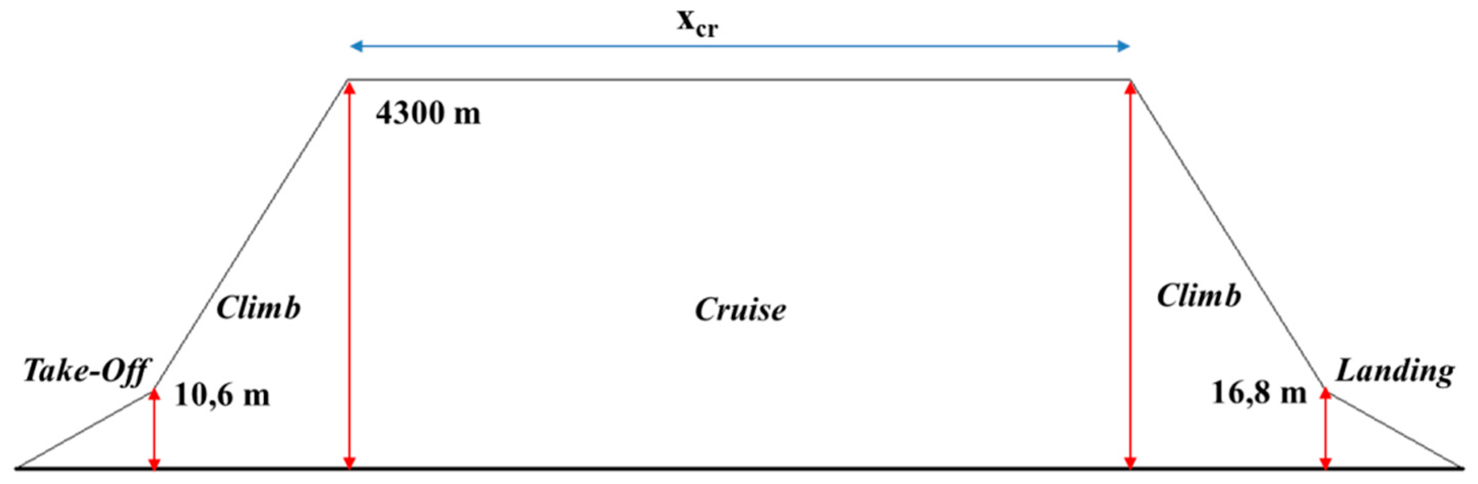
The solution of Equations (A1) and (1) permits the calculation of the take-off time and the total energy, Eto, required during this phase. It is imposed that the take-off starts at a level of 0 m and is completed at zto,f (about 10.6 m) [26]. The final condition of the battery pack is evaluated by calculating the required electrical power. These values are used as initial values for the next step in the optimization problem.

5.3. Solutions of Optimization Problems of Climb Ascendant/Descendent

The optimization of the climb phase is more complex with respect to that of take-off. In fact, in this case, an objective optimization is carried out inside the IDEA. The goal of this optimization is the minimization of the total energy required for the climb phase. The simulated climb phase is assumed to possess a uniform acceleration. Considering the fact that the climb phase commences at zto,f and the final altitude is the cruise altitude, zcr, it is also considered that the final speed must be equal to the cruise speed (in this case, any acceleration during the cruise phase is avoided). In the hypothesis of uniform acceleration, the altitude climb is divided in a certain number of divisions, in order to obtain that:
z c r z t o , f = k = 1 n d i v Δ z k
v c r = v f + k = 1 n d i v Δ v k
where Δvk is the variation of the velocity in each division. The used objective function is the total energy required in the climb:
min E c l ( x cl ) { g 1 ( x cl ) = 0 g 2 ( x cl ) = 0 g e q ( x cl ) = 0 s 1 ( x cl ) 0 s 2 ( x cl ) 0 s i n e q ( x cl ) 0
where the unknown variables are:
x cl = [ Δ v 1 , , Δ v n d i v , Δ z 1 , , Δ z n d i v , T 1 , , T n d i v , γ ]
Then, the objective function becomes:
min E c l ( x cl ) = min [ k = 1 n d i v T k ( v f + h = 1 k Δ v h ) Δ t k η b a t t η V S I η d c η m o t ]
In Equation (14), the sum of the energy calculated in each sub-interval considered for the climb phase is given. In particular, the numerator is presented as the product between the propeller trust, the velocity, and the time duration and this product is divided by the global efficiency of the electric propulsion chain.
The variation in the altitude and aircraft speed must satisfy the following equations:
{ g 1 ( x cl ) = z c r z t o , f k = 1 n d i v Δ z k g 2 ( x cl ) = v c r v f k = 1 n d i v Δ v k g 2 + k ( x cl ) = ( v f + h = 1 k Δ v h ) Δ v k Δ z k sin ( γ ) g W [ T k D k W sin ( γ ) ]
The first two equations are related to the fact that the final altitude and the final aircraft speed must be equal to the desired cruise altitude and cruise speed; therefore, the optimal value obtained for the altitude and speed variation in each sub-interval must be related to these values. The third equation relates the climb angle to all the dynamic variables.
The inequalities are:
{ 0 , 9 ( v c r v f n d i v ) Δ v k 1 , 1 ( v c r v f n d i v ) 0 , 9 ( z c r z t o , f n d i v ) Δ z k 1 , 1 ( z c r z t o , f n d i v ) 0 T k T max 0 γ γ max
The first two inequalities are used in order to limit the variation of the aircraft speed and altitude; the last two ensure that the maximum time for the climb phase and the climb angle are respected.
Starting from the final condition of the battery packs after take-off, the final state of charge and the final value of the open-circuit voltage Voc,sm are calculated. The same approach is used in the descendent phase of the climb.

5.4. Solutions of Dynamic Equations of the Cruise

The solution of Equation (A5) gives the operation characteristics of the cruise. In particular, the cruise range, xcr, is used as the objective function in the optimization procedure. According to the control strategy, during the cruise, all the power is obtained by the thermal engine coupled with the electric generator; therefore, it is possible to assume that the state of charge (SoC) of the battery is essentially constant and equal to the final values obtained in the ascendant climb phase, and will be modified only in the descendent climb phase. At each iteration, whether the power chosen for the ICE is sufficient to guarantee the required trust at the cruise speed is determined.
As previously mentioned, the landing phase is not considered in the simulations because a large part of the energy needed to decelerate the aircraft can be provided by the mechanical braking of the propeller.

5.5. Check of the Optimization Procedure Constraints and Choice of Objective Function

The output obtained by the solutions of mechanical flights and the electric state of the battery storage system are used to verify some constrains applied to the differential evolution optimization.
Specifically, two different problems are analyzed. In the first problem there is the minimization of difference between the cruise range and a target cruise value; the approach allows for a trade-off between the battery mass and fuel mass, which guarantees a certain cruise range. The adopted problem could be applied to a training course and in the application no fuel reserve is considered. The constrains are inherent to:
-
the respect of the maximum take-off aircraft mass;
-
the final SoC of the battery;
-
the maximum duty-ratio between the output voltage battery pack and the required DC-link voltage;
-
the energy stored in the battery pack must be at least equal to the energy required in the take-off and in the climb phase;
-
the maximum value of the discharge current of the battery pack in the take-off and climb phases must be below the maximum discharge current of the battery cells used.

5.5.1. Problem 1

min ( x c r x c r , t a r ) { n p n s m s , c + m f u e l + m m , o + m p a y < = m m , t o S o C f i n > 20 % V d c V o c , s m , f i n < d max n p n s m s , c δ b a t t ( E t o + E c l ) max [ I b , m , d e c , I b , m , c l ] < I max , b , p
The second problem is related to the reduction in the battery costs: the minimization of the energy surplus contained in the battery (this surplus comes from the fact that the modules are defined as integer numbers) reduces the weight of the aircraft (or increases the amount of fuel with an increase in the cruise range) as well as the cost of battery installations.

5.5.2. Problem 2

min [ n p n s m s , c δ b a t t ( E t o + E c l ) ] max ( x c r ) { n p n s m s , c + m f u e l < = m m , t o S o C f i n > 20 % V d c V o c , s m , f i n < d max max [ I b , m , d e c , I b , m , c l ] < I max , b , p
The goal of Problem 1 is linked to the optimization of the fuel weight; it has to provide a trade-off between the battery mass and fuel mass which maximizes the cruise. Problem 2 is related to the reduction in the battery costs: the minimization of the energy surplus contained in the battery (this surplus comes from the fact that the modules are defined as integer numbers) reduces the weight of the aircraft (or increases the amount of fuel with an increase in the cruise range) as well as the cost of battery installations.

5.6. Crossover Operations and Check of Maximum Iterations Limit

As presented in [25], the crossover conserves the original characteristics of the population and also, introduces a new diversity, with an effect similar to genetic algorithms and other heuristics methods. The crossover works are as follows: if the generated solution satisfies all the constraints of the optimization problem and, therefore, becomes a possible new solution, the crossover introduces a new probabilistic constraint. That is, the replacement of the determined solution only occurs if a generated number is greater than a certain threshold value. If that happens, and the number of iterations of the system is below the maximum number of iterations, the procedure is finished. If the value of the obtained objective functions is greater than the value of an element of the starting populations, the new populations replace the old elements of the populations. Otherwise, the procedure is tried again. When the maximum number of iterations is reached, the minimum (or maximum, depending on the objective function) of the final populations is the optimal value.

6. Simulation Results

The performance of the proposed optimization procedure is verified by means of numerical simulations implemented in Matlab ©. The aircraft parameters are reported in Table 1; the parameters are the same as those of Tecnam P2006T [28], where it is supposed that the ICEs are substituted with an electric motor with the same power, and the empty aircraft mass is unchanged. The ICE considered for the hybrid flight has a maximum power less than the total power of the electric motor because it operates only in the cruise phase, when the required trust is usually below the maximum power of the propeller motors. The evaluation of the optimum value of rated power for the electric motor and of the maximum power of the ICE is not considered in this paper.
The simulation refers to the flight profile reported in Figure 5. In Table 2, the main parameters of the considered battery pack are reported. The first simulation reported demonstrates the convergence of the optimization problems. For each problem, other simulations using different cells [29] and two different voltages for the DC-link are carried out.

6.1. Simulation of Problem 1

The problem described by Equation (17) is simulated, imposing a maximum value of dmax = 6.5. An initial population of npop = 8 is generated, and the values α, ρ1, ρ2, ρ3 and the threshold for the crossover operations are obtained using the random generators of Matlab. The number of mutation substitutions is set as 100. The cruise range is fixed as 180 km. The final optimized values obtained for 11 Ah batteries with a continuous discharge rate of 8 C and a DC-link voltage of 270 V, are reported in Table 3.
Figure 6 and Figure 7 show the trends of mutation substitutions of the battery module numbers (both in series and parallel) of the fuel mass and the cruise range. It is possible to note that the convergence of the method occurs at approximately 40 iterations. In Figure 8, the trends in SoC and the maximum current in the climb phase are reported.
In Table 4, the results obtained for different cells (with equal nominal voltage and parameters d0 and d1) and for an inverter DC-link of 270 V and 540 V are shown.
It is evident that the cruise range is closer to the fixed value, but the final SoC is higher than that in the case of the DC-Link at 270 V. This happens because the number of cells is increased to respect the maximum duty cycle imposed for the DC–DC converter. It can be concluded that the excess stored energy can also be used for the reduction of pollutant emissions and to increase the cruise range.

6.2. Simulation of Problem 2

The problem described by Equation (18) is simulated, imposing a maximum value of dmax = 6.5 and the number of iterations is 100. The parameters for the IDEA are calculated in the same manner as in Problem 1. The optimal solution obtained for 11 Ah batteries with a continuous discharge rate of 8 C and a DC-link voltage of 270 V is indicated in Table 5.
Figure 9 and Figure 10 show the trends of the mutation substitution of battery module numbers in series and in parallel, and the variation of the energy stored in excess and in the cruise range.
The results of simulations demonstrate that, in Problem 2, the type of optimization used enables the cruise range to be increased while reducing the energy stored in excess in the battery pack. This is due to the relationship between the fuel mass and the energy stored in the battery: if the fuel mass increases, more energy is needed for the take-off and climb phases, resulting in greater utilization of the battery and an increase in the cruise range as shown in Figure 11.
In Table 6, the results obtained for Problem 2 are reported and related to different types of cells and two voltage levels of the DC-link. With respect to the results of Problem 1, in this case it is possible to note that the use of a higher value for the DC-link improves the performance of the aircraft, especially for the maximization of the cruise range. Furthermore, the minimization of the residual energy stored in the batteries is also evident for the DC-link of 540 V.
As mentioned in Table 1, in the mission profile, the presence of at least one passenger must be guaranteed. From the calculation of the total mass required by the mission profile it is possible to obtain that for both; the best payloads are obtained with a DC-link of 270 V and with a battery of 16 Ah. Specifically, the maximum payload for Problem 1 is about 313 kg and is about 211 kg for Problem 2. This confirms the respect of all the constraints (electrical and mechanical) and highlights the possibility to effectively optimize the pre-flight settings of the aircraft.
Regarding the convenience of the hybrid technologies, it is possible to highlight the following results:
-
with the series topologies adopted, the emissions during the take-off and climb phases are eliminated; these are the parts of the flight that occur close to built-up areas, such as cities;
-
to date, an economically beneficial way to replace a traditional piston engine aircraft with a hybrid propelled aircraft does not exist. In fact, excluding the cost of the electric powertrain and considering only the battery costs of $176/kWh [29], a cost of $30,000 regarding implementing a hybrid propelled aircraft for the first problem and a cost of $34,500 for the second one is obtained. Evidently, the introduction of a new battery type or the rapid increase of the battery energy density, will dramatically increase the viability of hybrid/all-electric technologies.

6.3. Verification of the Results Through the Real-Time Simulations of the Battery Pack

Real-time simulations of the performance of the battery pack during the take-off and climb phases are carried out with Simulink©. The battery cells are modeled according to [27] and using the parameters of the Kokam cells [30]. The simulations performed are related to the results obtained in Problem 1 and for the cases of an 11 Ah cell (Table 4). The results for a DC-link voltage of 270 V are depicted in Figure 12, while the case of 540 V is shown in Figure 13.
As it is possible to note in both the cases, the final values of SoC are very close to the value obtained from the optimization. In this way, real-time simulations demonstrate the effectiveness of the proposed optimization procedure.

7. Conclusions

All electric aircraft and the hybrid electric aircraft are currently feasible technologies which can be applied to UAVs and passenger aircraft. A crucial problem is the correct integration and sizing of the storage systems utilized on board. This factor influences the performance of the aircraft in terms of battery and fuel costs, flight distance range and flight time, and safety. An optimization procedure for a series-hybrid aircraft has been proposed in this paper based on an integer differential evolution approach, which taking into account the electrical and flight mechanical behavior of the aircraft, gives the optimal trade-off between the battery size and the mass of fuel. The series-hybrid architecture provides a take-off and climb phase (both ascendant and descendent) in the electric mode, with the goal of reducing the noise emission and pollution in the phase when the aircraft is nearest to the airport. The sizing optimization procedure has been applied to a real case and validated by implementing numerical simulations in Matlab, and the results have been verified by real-time scenario simulations. The results demonstrate the fast convergence of the method and the importance of the main electrical parameters (such as the DC-link voltage) in the application. The proposed procedure respected all the electrical and mechanical constraints and also determines the minimum payload which must be guaranteed in the aircraft. Future work will include the optimization of the power-train performance with the integration of the energy store optimization and the optimization of the drives control and the propulsion motor sizing procedure.

Author Contributions

L.S.B., L.P.D.N., R.R. contributed equally to the paper. Formal analysis, L.S.B., L.P.D.N. and R.R.; investigation, L.S.B., L.P.D.N. and R.R.; methodology, L.S.B., L.P.D.N. and R.R.; validation, L.S.B., L.P.D.N. and R.R.

Funding

This research received no external funding.

Conflicts of Interest

The authors declare no conflicts of interest.

Nomenclature

c0Parameter 1 of battery voltage
c1Parameter 2 of battery voltage
CdPolar coefficient
Cd0Zero-lift coefficient
ClLift coefficient
Cl,maxMaximum value of lift coefficient
DDrag force (N)
dmaxRatio of DC-link and battery voltage
EclRequired energy during the climb (J)
EtoRequired energy during the take-off (J)
gGravity acceleration (m/s2)
hAltitude (m)
HEnergy density of fuel (J/kg)
Ib,mCurrent value of modules of batteries (A)
Ib,m,decCurrent value during the take-off (A)
Ib,n,clCurrent value during the climb (A)
Imax,b,pMaximum discharge current values (A)
KAerodynamic generic coefficient
LLift (N)
mfuel,totMass of fuel (kg)
mfuel,reserveMass of fuel used for the reserve (kg)
mm,toMass of aircraft at take-off (kg)
ms,cMass of a battery module (kg)
npNumber of parallel battery modules
nsNumber of series battery modules
QbBattery capacity (Ah)
RGround friction force (N)
RbInternal resistance of battery (Ω)
SSurface of aircraft (m2)
SoCState of charge of the battery pack
SoCfinFinal value of the state of charge
tTime variable (s)
TTrust (N)
TkTrust of k-th subdivision of the climb phase (N)
tfFinal time of flight (s)
toInitial time of flight (s)
vAircraft speed (m/s)
VdcVoltage of DC-link of the VSI (V)
vfFinal speed at take-off (m/s)
Voc,smOpen-circuit voltage of batteries (V)
Voc,sm,finFinal open-circuit voltage of batteries (V)
WTotal weight of the aircraft (N)
WfTotal weight of the aircraft without fuel (N)
xDistance variable (m)
xcrCruise range (m)
xtoTake-off range (m)
zcrCruise altitude (m)
zto,fTake-off final altitude (m)
γClimb angle (rad)
δbattEnergy density of battery module (J/kg)
ΔvkSpeed variation during climb interval (m/s)
ΔzkAltitude variation during clim interval (m)
ΔtkDuration of k-th climb phase sub-interval (m)
ηbattBattery efficiency
ηVSIVSI efficiency
ηdcDC–DC converter efficiency
ηmotElectric motor efficiency
μFriction coefficient
ρAir density (kg/m3)

Appendix A

Take-Off Dynamics Equations
Considering that the vector which determines the trust force is parallel to the ground, the mathematical model of dynamics equations of the aircraft is,
{ d x d t = v d v d t = g W [ T D μ R ] R = W L .
In this case, the variable W contains the constant weight of the battery and the weight of AVGAS, which is also kept constant because the take-off is realized only with the electric propulsion. The flight begins when the final velocity is reached: its value is 20% greater than the stall speed, defined as,
v f = 1 , 2 2 W ρ S C l , max .
Regarding the drag force, this value is calculated using the well-known formula:
D = 1 2 ρ C d 0 S   v 2 + 2 K ρ S ( L v ) 2 .
Climb Phase Dynamics Equations
The dynamics equations of climb phase are
{ 0 = L W cos γ d v d t = g W [ T D W sin γ ] d x d t = v cos γ d h d t = v sin γ .
Cruise Phase Dynamic Equations
The dynamics equations of the cruise are
{ L = W T = D d h d t = 0 d x d t = v .

References

  1. Wheeler, P. Technology for the more and all electric aircraft of the future. In Proceedings of the 2016 IEEE International Conference on Automatica (ICA-ACCA), Curico, Chile, 19–21 October 2016; pp. 1–5. [Google Scholar]
  2. Li, J.; Yu, Z.; Huang, Y.; Li, Z. A review of electromechanical actuation system for more electric aircraft. In Proceedings of the IEEE International Conference on Aircraft Utility Systems (AUS), Beijing, China, 10–12 October 2016; pp. 490–497. [Google Scholar]
  3. Chen, J.; Wang, C.; Chen, J. Investigation on the Selection of Electric Power System Architecture for Future More Electric Aircraft. IEEE Trans. Transp. Electrif. 2018, 4, 563–576. [Google Scholar] [CrossRef]
  4. Buticchi, G.; Costa, L.; Liserre, M. Improving System Efficiency for the More Electric Aircraft: A Look at dc/dc Converters for the Avionic Onboard dc Microgrid. IEEE Ind. Electron. Mag. 2017, 11, 26–36. [Google Scholar] [CrossRef]
  5. Gohardani, A.S.; Doulgeris, G.; Singh, R. Challenges of future aircraft propulsion: A review of distributed propulsion technology and its potential application for the all-electric commercial aircraft. Prog. Aerosp. Sci. 2011, 47, 369–391. [Google Scholar] [CrossRef]
  6. Ciccarelli, F.; Fantauzzi, M.; Lauria, D.; Rizzo, R. Special transformers arrangement for AC railway systems. In Proceedings of the International Conference Electrical Systems for Aircraft, Railway and Ship Propulsion (ESARS 2012), Bologna, Italy, 16–18 October 2012. [Google Scholar] [CrossRef]
  7. Del Pizzo, A.; Di Noia, L.P.; Marulo, F. Design considerations on energy storage system for electric aircraft propulsion. In Proceedings of the 2016 AEIT International Annual Conference, Capri, Italy, 5–7 October 2016; pp. 1–6. [Google Scholar]
  8. Hoelzen, J.; Liu, Y.; Bensmann, B.; Winnefeld, C.; Elham, A.; Friedrichs, J.; Hanke-Rauschenbach, R. Conceptual Design of Operation Strategies for Hybrid Electric Aircraft. Energies 2018, 11, 217. [Google Scholar] [CrossRef]
  9. Neuman, T. Fly the electric skies. IEEE Spectr. 2016, 53, 44–48. [Google Scholar] [CrossRef]
  10. Leuchter, J.; Zobaa, A.F. Batteries investigations of small Unmanned Aircraft Vehicles. In Proceedings of the 8th IET International Conference on Power Electronics, Machines and Drives (PEMD 2016), Glasgow, UK, 19–21 April 2016; pp. 1–6. [Google Scholar]
  11. Tariq, M.; Maswood, A.I.; Gajanayake, C.J.; Gupta, A.K. Aircraft batteries: Current trend towards more electric aircraft. IET Electr. Syst. Transp. 2017, 7, 93–103. [Google Scholar] [CrossRef]
  12. Thauvin, J.; Barraud, G.; Roboam, X.; Sareni, B.; Budinger, M.; Leray, D. Hybrid propulsion for regional aircraft: A comparative analysis based on energy efficiency. In Proceedings of the International Conference ESARS-ITEC, Toulouse, France, 2–4 November 2016; pp. 1–6. [Google Scholar]
  13. Rashed, M.; Le Peuvedic, J.M.; Bozhko, S. Conceptual design of battery energy storage for aircraft hybrid propulsion system. In Proceedings of the International Conference ESARS-ITEC, Toulouse, France, 2–4 November 2016; pp. 1–6. [Google Scholar]
  14. Pornet, C.; Isikveren, A.T. Conceptual design of hybrid-electric transport aircraft. Prog. Aerosp. Sci. 2015, 79, 114–135. [Google Scholar] [CrossRef]
  15. Di Noia, L.P.; Genduso, F.; Miceli, R.; Rizzo, R. Optimal Integration of Hybrid Supercapacitor and IPT System for a Free-Catenary Tramway. IEEE Trans. Ind. Appl. 2019, 55, 794–801. [Google Scholar] [CrossRef]
  16. Hung, J.Y.; Gonzalez, L.F. On parallel hybrid-electric propulsion system for unmanned aerial vehicles. Prog. Aerosp. Sci. 2012, 51, 1–17. [Google Scholar] [CrossRef] [Green Version]
  17. Sabri, M.F.M.; Danapalasingam, K.A.; Rahmat, M.F. A review on hybrid electric vehicles architecture and energy management strategies. Renew. Sustain. Energy Rev. 2016, 53, 1433–1442. [Google Scholar] [CrossRef]
  18. Antcliff, K.R.; Capristan, F.M. Conceptual Design of the Parallel Electric-Gas Architecture with Synergistic Utilization Scheme (PEGASUS) Concept. In Proceedings of the 18th AIAA/ISSMO Multidisciplinary Analysis and Optimization Conference, Denver, CO, USA, 5–9 June 2017. [Google Scholar]
  19. Ostadi, A.; Kazerani, M. Optimal sizing of the battery unit in a plug-in electric vehicle. IEEE Trans. Veh. Technol. 2014, 63, 3077–3084. [Google Scholar] [CrossRef]
  20. Tara, E.; Shahidinejad, S.; Filizadeh, S.; Bibeau, E. Battery storage sizing in a retrofitted plug-in hybrid electric vehicle. IEEE Trans. Veh. Technol. 2010, 59, 2786–2794. [Google Scholar] [CrossRef]
  21. Araujo, R.E.; de Castro, R.; Pinto, C.; Melo, P.; Freitas, D. Combined sizing and energy management in EV switch batteries and supercapacitors. IEEE Trans. Veh. Technol. 2014, 63, 3062–3076. [Google Scholar] [CrossRef]
  22. Geiß, I.; Voit-Nitschmann, R. Sizing of the energy storage system of hybrid-electric aircraft in general aviation. CEAS Aeronaut. J. 2017, 8, 53–65. [Google Scholar] [CrossRef]
  23. Saenger, P.; Devillers, N.; Deschinkel, K.; Péra, M.C.; Couturier, R.; Gustin, F. Optimization of Electrical Energy Storage System Sizing for an Accurate Energy Management in an Aircraft. IEEE Trans. Veh. Technol. 2017, 66, 5572–5583. [Google Scholar] [CrossRef]
  24. Saenger, P.; Deschinkel, K.; Devillers, N.; Pera, M.C. An Optimal Sizing of Electrical Energy Storage System for an Accurate Energy Management in an Aircraft. In Proceedings of the IEEE Vehicle Power and Propulsion Conference (VPPC), Montreal, QC, Canada, 19–22 October 2015. [Google Scholar]
  25. Avanzini, G.; de Angelis, E.L.; Giulietti, F. Optimal performance and sizing of a battery-powered aircraft. Aerosp. Sci. Technol. 2016, 59, 132–144. [Google Scholar] [CrossRef]
  26. Lin, Y.C.; Wang, F.S.; Hwang, K.S. A hybrid method of evolutionary algorithms for mixed-integer nonlinear optimization problems. In Proceedings of the 1999 Congress on Evolutionary Computation (CEC99), Washington, DC, USA, 6–9 July 1999. [Google Scholar]
  27. Hu, X.; Murgovski, N.; Johannesson, L.; Egar, B. Energy efficiency analysis of a series plug-in hybrid electric bus with different energy management strategies and battery sizes. Appl. Energy 2013, 111, 1001–1009. [Google Scholar] [CrossRef]
  28. Pascale, L.; Nicolosi, F. Design of a twin engine propeller aircraft; aerodynamic investigation on fuselage and nacelle effects. In Proceedings of the XIX Congresso Nazionale AIDAA, Forlì, Italy, 17–20 September 2007. [Google Scholar]
  29. Goldie-Scot, L. A Behind the Scenes Take on Lithium-Ion Battery Prices. Available online: https://about.bnef.com/blog/behind-scenes-take-lithium-ion-battery-prices/ (accessed on 30 April 2018).
  30. Kokam Cells. Available online: http://www.kokam.com/ (accessed on 30 April 2018).
Figure 1. Series-hybrid architecture of the propulsion.
Aerospace 06 00059 g001
Figure 2. Variation of series-hybrid architecture of the propulsion.
Aerospace 06 00059 g002
Figure 3. Scheme of a battery pack.
Aerospace 06 00059 g003
Figure 4. Flow chart of the optimized procedure solutions of dynamics equations of take-off.
Aerospace 06 00059 g004
Figure 5. Considered mission profile.
Aerospace 06 00059 g005
Figure 6. Variation of solutions for the number of modules in optimization Problem 1.
Aerospace 06 00059 g006
Figure 7. Variation of solutions for the fuel mass and cruise range in optimization Problem 1.
Aerospace 06 00059 g007
Figure 8. Variation of state of charge (SoC) of the battery pack and the current in the climb phase in optimization Problem 1.
Aerospace 06 00059 g008
Figure 9. Variation of solutions for the number of modules in optimization Problem 2.
Aerospace 06 00059 g009
Figure 10. Variation of solutions for the fuel mass and cruise range in optimization Problem 2.
Aerospace 06 00059 g010
Figure 11. Variation of SoC and the current in the climb phase in optimization Problem 2.
Aerospace 06 00059 g011
Figure 12. Real-time simulation of the case 11 Ah, np = 21, ns = 29, 270 V on the DC-link: SoC (blue line) and output voltage (green line).
Aerospace 06 00059 g012
Figure 13. Real-time simulation of the case 11 Ah, np = 21, ns = 29, 540 V on the DC-link: SoC (blue line) and output voltage (green line).
Aerospace 06 00059 g013
Table 1. Main parameters of the aircraft selected as a case study.
ParameterValue
Number of electric motors2
Number of thermal engines1
Rated power electric motor75 kW
Maximum power of thermal engine100 kW
DC-link voltage270 V
Number of passengers1
Maximum cruise speed260 km/h
Wing area14.8 m2
Empty aircraft mass760 kg
Maximum take-off mass1230 kg
Zero-lift drag coefficient Cd00.025
Table 2. Main parameters of the considered lithium battery pack.
ParameterValue
Rated voltage3.7 V
Battery capacity11 Ah
c03 V
c11.2 V
Imax,b,p88 A
Table 3. Final values of Problem 1.
ParameterValue
np21
ns29
mfuel,tot22 kg
xcr190 km
SoCfin44%
Table 4. Problem 1 for different cells and the DC-link voltage.
Q [Ah]Continuous Discharge RateVdc [V]npnsmfuel,tot [kg]SoCfin [%]xcr [km]
7.5527019452247.2192
11827021292244.6190
165270104020.547.6180
7.5554024462155.6180
11854025422163.4180
16554025232150.2182
Table 5. Final values of Problem 2.
ParameterValue
np25
ns28
mfuel,tot105 kg
xcr729 km
SoCfin44.4%
Energy stored in excess12.65 kWh
Table 6. Problem 2 for different cells and DC-link voltages.
Q [Ah]Continuous Discharge RateVdc [V]npnsmfuel,tot [kg]mfuel,reserve [kg]SoCfin [%]xcr [km]
7.55270293410520.947774
118270252810121.144.4729
165270261810020.947.3728
7.55540129211221.149834
118540135811321.246.8837
165540312311121.344.3811

