Article

A Numerical–Analytical Approach for the Preliminary Design of Thin-Walled Cylindrical Shell Structures with Elliptical Cut-Outs

Department of Engineering, University of Campania “Luigi Vanvitelli”, via Roma 29, Aversa, Italy
*
Author to whom correspondence should be addressed.
These authors contributed equally to this work.
Aerospace 2019, 6(5), 52; https://doi.org/10.3390/aerospace6050052
Submission received: 5 March 2019 / Revised: 26 April 2019 / Accepted: 29 April 2019 / Published: 6 May 2019
(This article belongs to the Special Issue Structural Stability of Aerospace Structures)

Abstract

:
The presence of cut-outs within thin-walled shell structures is unavoidable, holes being needed for the passage of electrical cables, fuel, or just to reduce the weight of the components. Nevertheless, the high stress concentration can lead to a premature collapse of the structure. For this reason, the preliminary design of cylindrical shell structures with holes needs a profound knowledge of the stress distribution for different loading conditions and constraints. In this paper, a parametric study of a fiber-reinforced composite shell cylinder with an elliptical cut-out has been performed. Three different loading conditions were analyzed: Tension, bending, and torsion. Ansys® script, capable of easily generating and analyzing different geometrical configurations, was used to study the dependence of the geometry on the stress distribution near the cut-out. Finally, graphical and analytical relationships were tentatively extrapolated from numerical results, aimed at linking the geometrical parameters of the cut-out to the maximum stress near the cut-out.

1. Introduction

Thin-walled cylindrical structures are increasingly adopted in the frame of many engineering applications due to their inherent lightweight characteristics; however, they are prone to undergoing critical instability phenomena related mainly to their slimness, boundary conditions, and imperfections. Imperfections include geometrical imperfections depending on the manufacturing process, load eccentricity but also cut-outs and holes. The application of cut-outs within cylindrical thin-walled structures for aeronautical applications cannot be avoided, holes being necessary for the realization of doors and windows or for the presence of electrical cables and pipes. As a matter of fact, the structural response of a thin-walled cylindrical component can significantly change in proximity to cut-outs due to the high stresses’ and deformations’ concentration [1,2,3,4]. For such a reason, the preliminary design of a notched cylindrical shell structures requires an in-depth understanding of the stress concentration for different loading conditions and constraints. In literature, several analytical, numerical, and experimental studies have been conducted to determine the stress distribution in a cylindrical shell with cut-outs, subject to various loading conditions, like traction, bending, torsion, and internal/external pressure. The first analytical studies were conducted in [5,6] to investigate the effects of axial load and internal pressure, together with the cylinders’ curvature, on the stress concentration near circular cut-outs. Subsequently, analytical studies were presented in [7,8,9,10,11,12], which further examined the effect of different loading conditions on the stress concentration in cylindrical structures with various sizes and shape notches. Experimental assessment was presented in [13], where the effects of circular holes in cylindrical shells under axial compression were studied. It was found that significant reductions in the buckling load of cylindrical shell structures, due to the presence of relatively small unreinforced cut-outs, can be found. In [14], the stress state near an elliptic cut-out in a circular cylindrical shell structure, under axial load, was experimentally measured. Different ellipse eccentricities and curvature parameters were analyzed. Zirka et al.; in [15], experimentally determined the stress concentrations in proximity to elliptical and circular holes in a cylindrical shell made of epoxy resin. A numerical approach, able to predict the mechanical behavior of composite 3D shells with circular holes and with different configurations in terms of material and structural parameters, was presented in [16]. Experimental and numerical analyses were performed by Yazici et al. in [17], where the influence of cut-out shapes on the buckling behavior of rectangular glass/epoxy plates, with different orientation angles, was studied. In [17], robust numerical techniques, to study the stresses’ and deformations’ concentrations near the cut-outs in composites thin-walled structures, proved to be mandatory in the design stage.
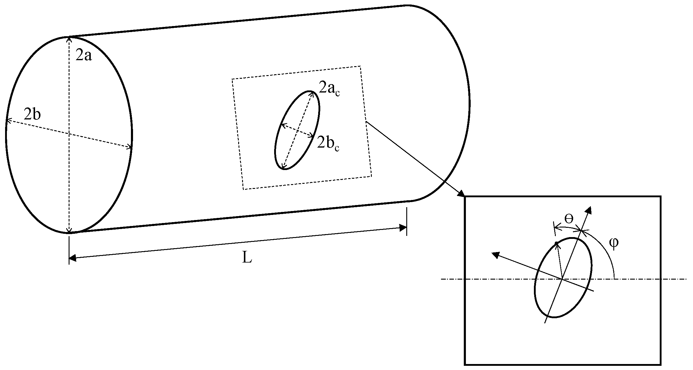
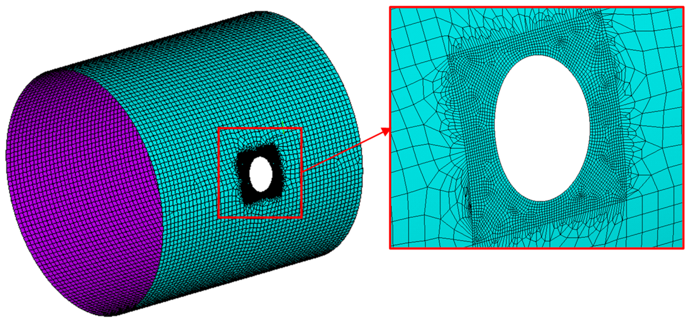
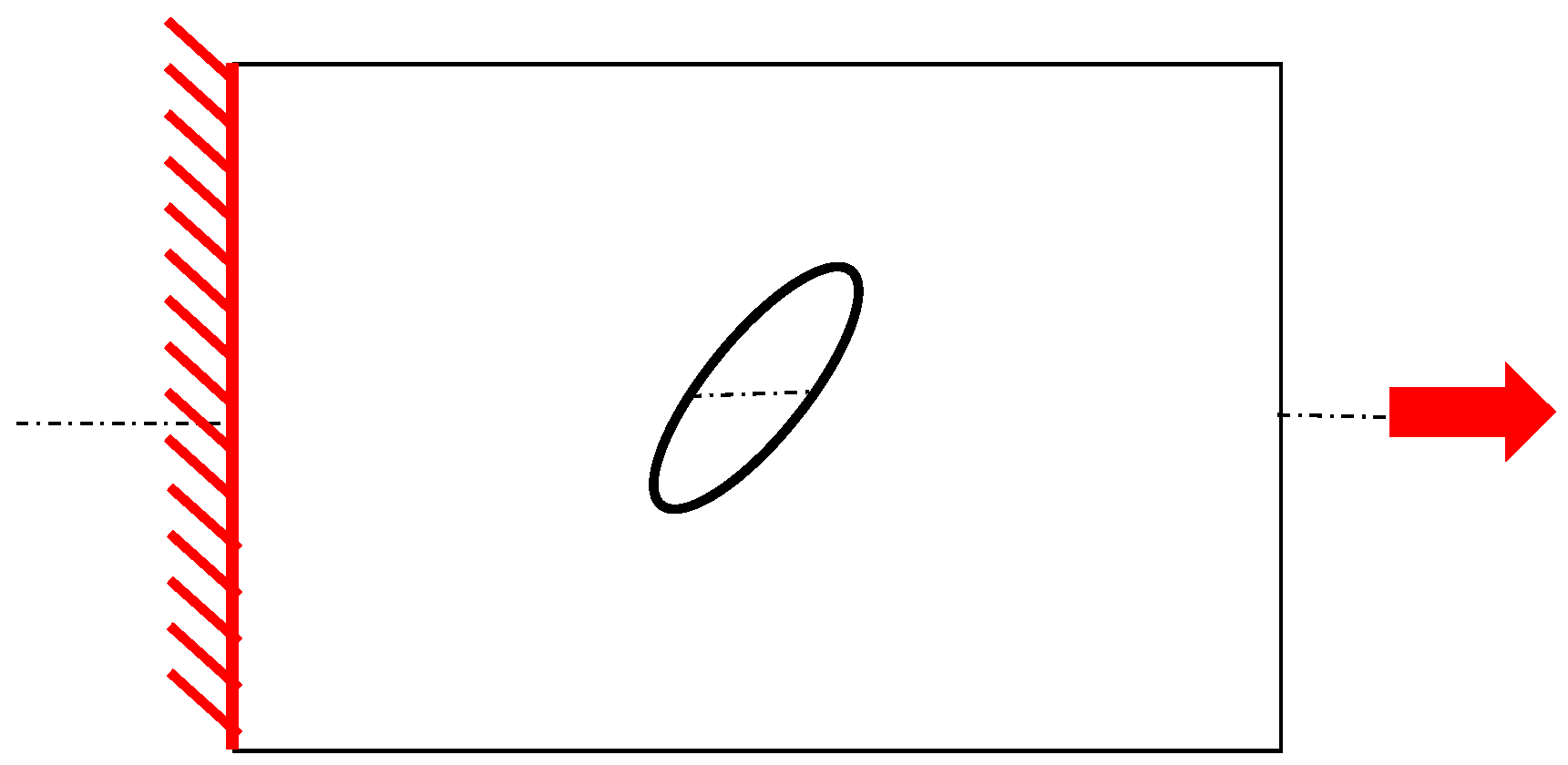
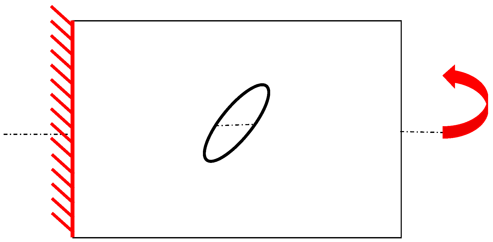
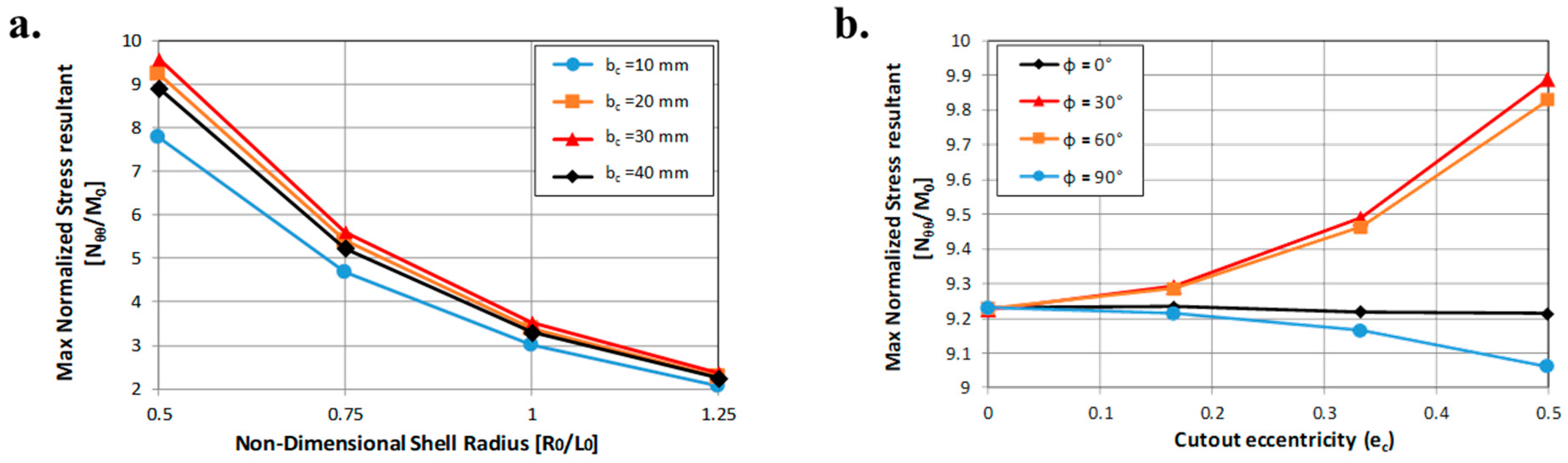
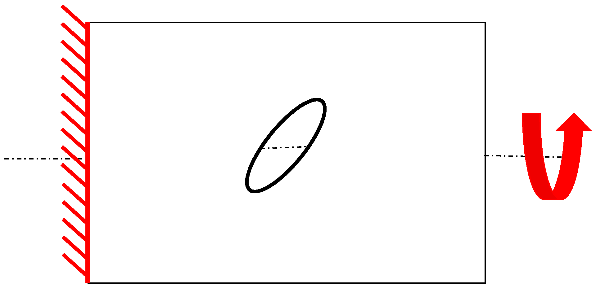
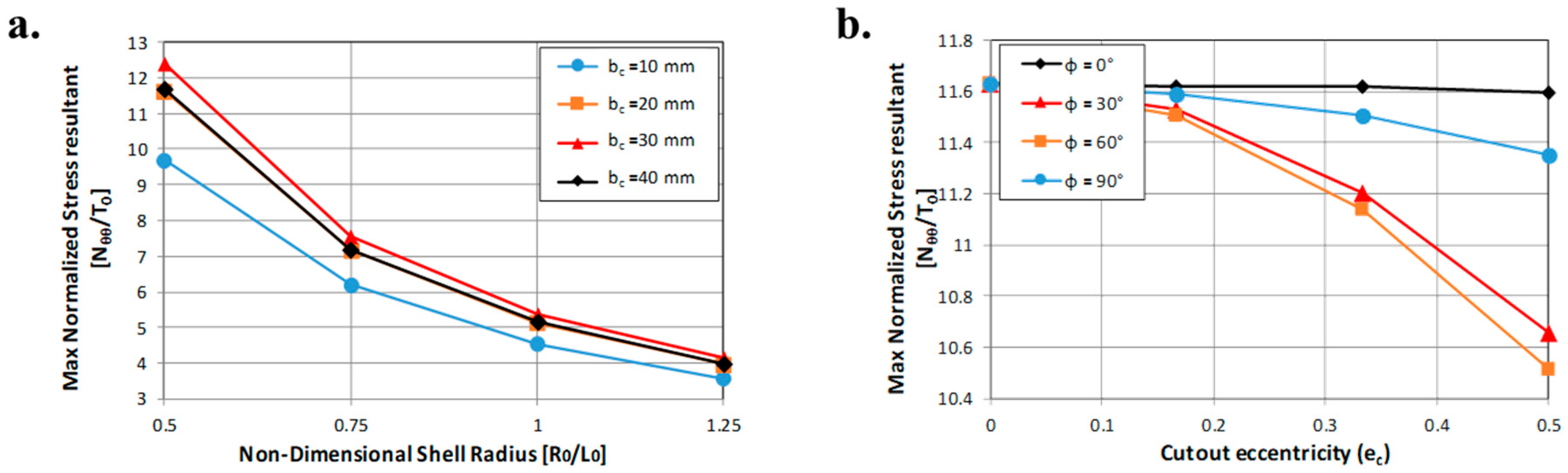
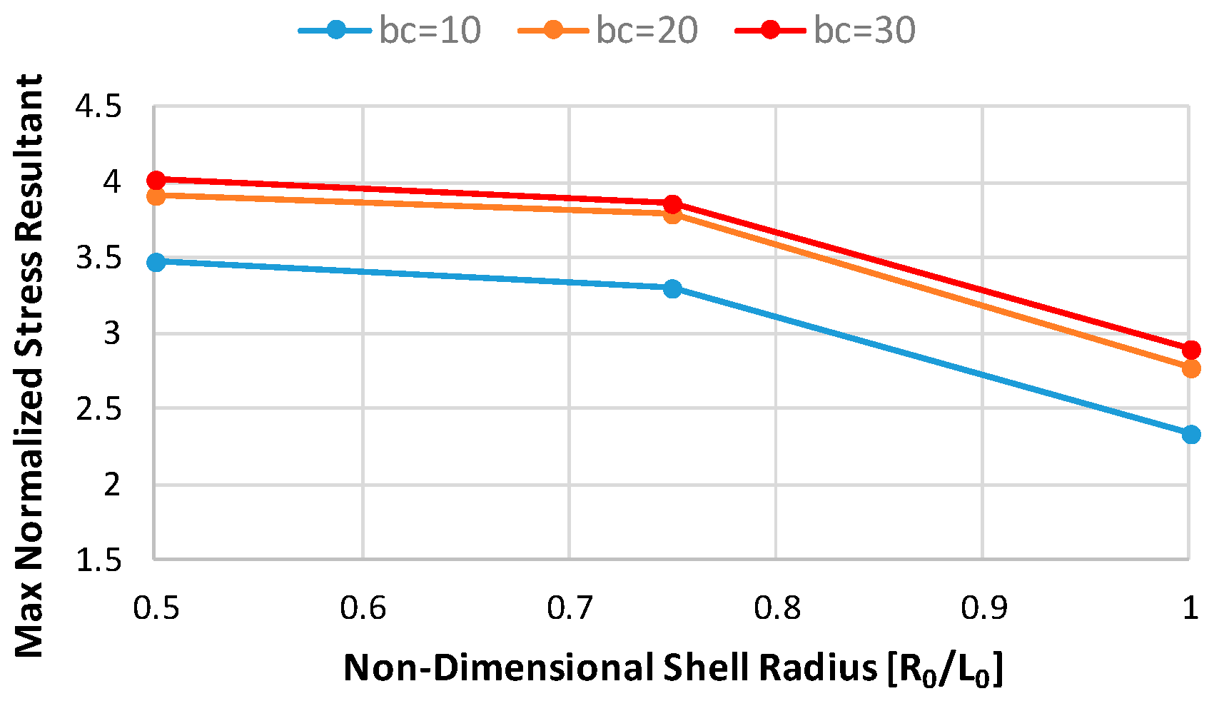
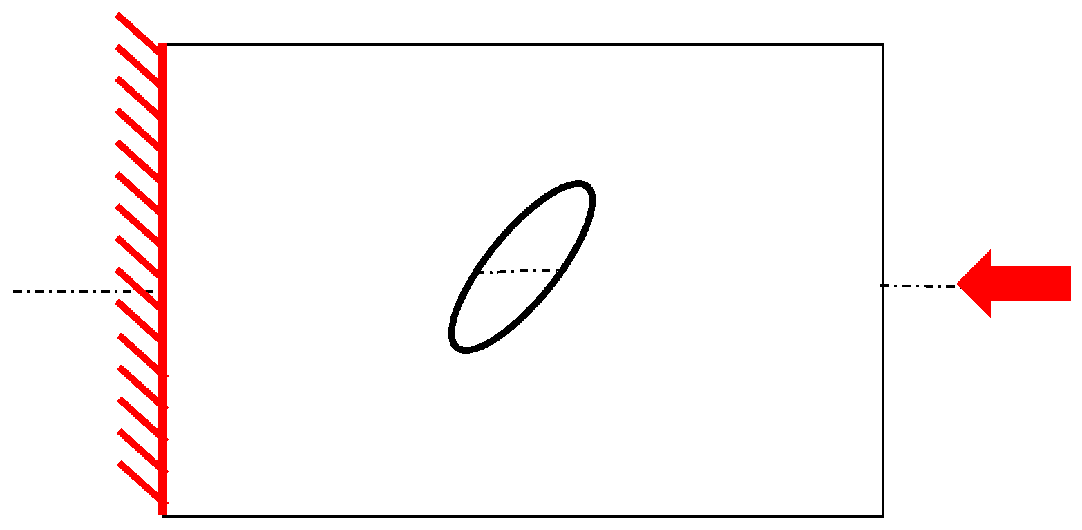
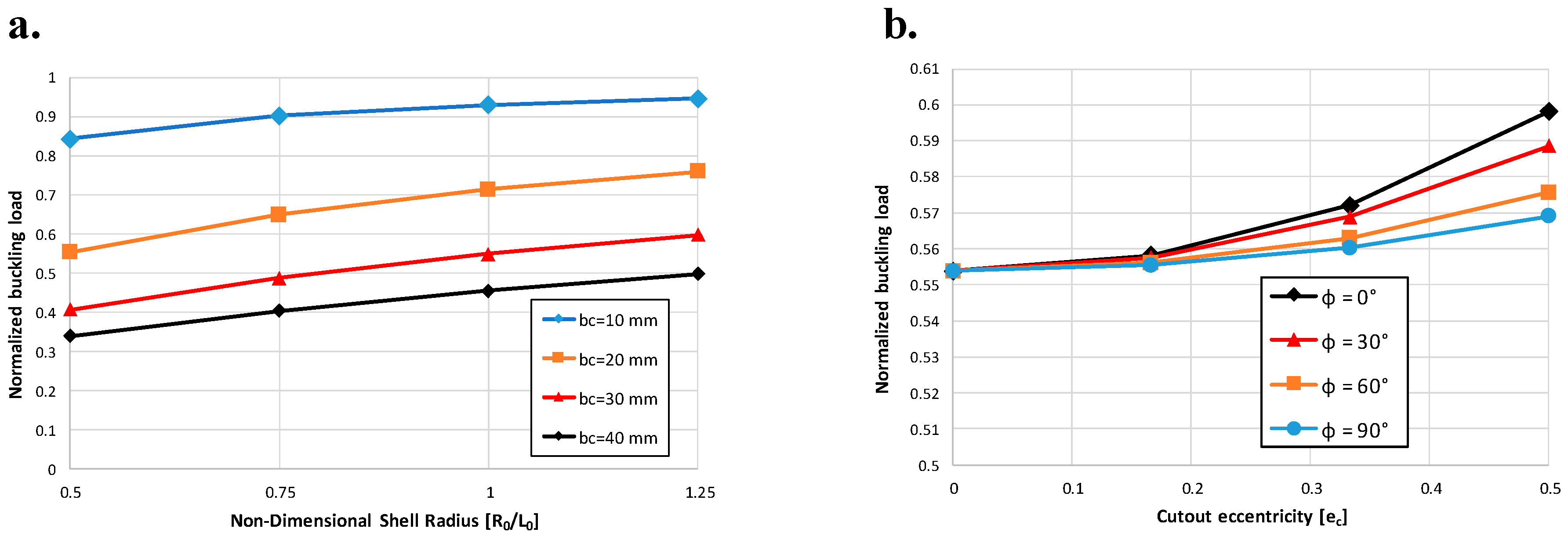
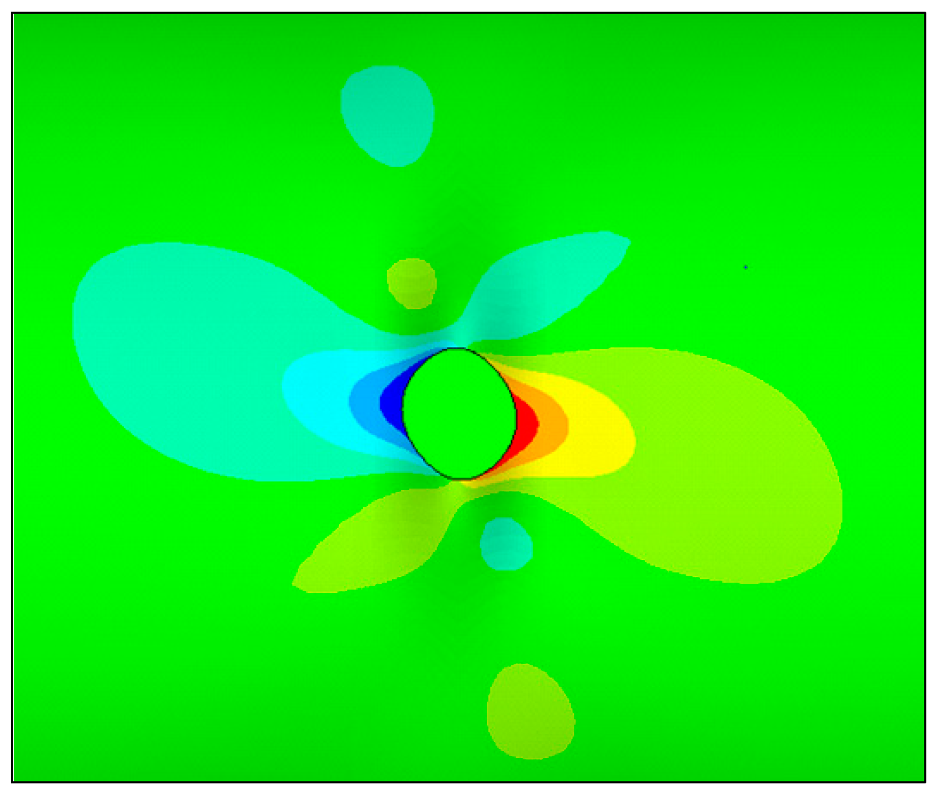
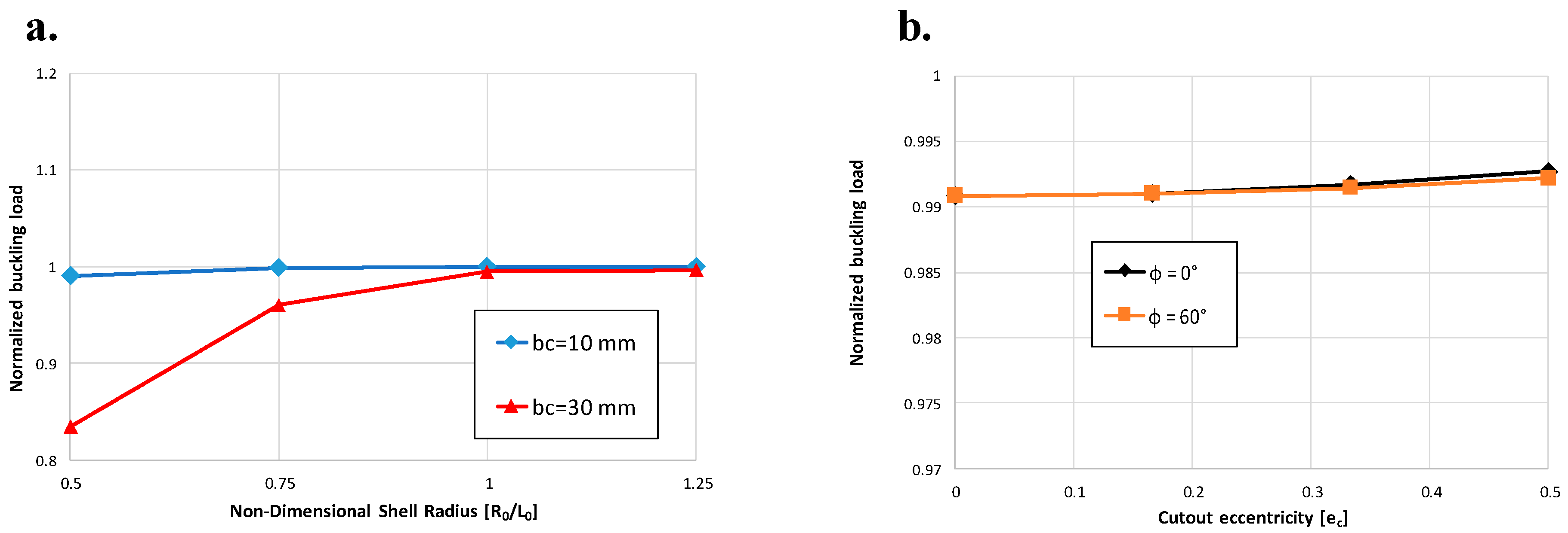
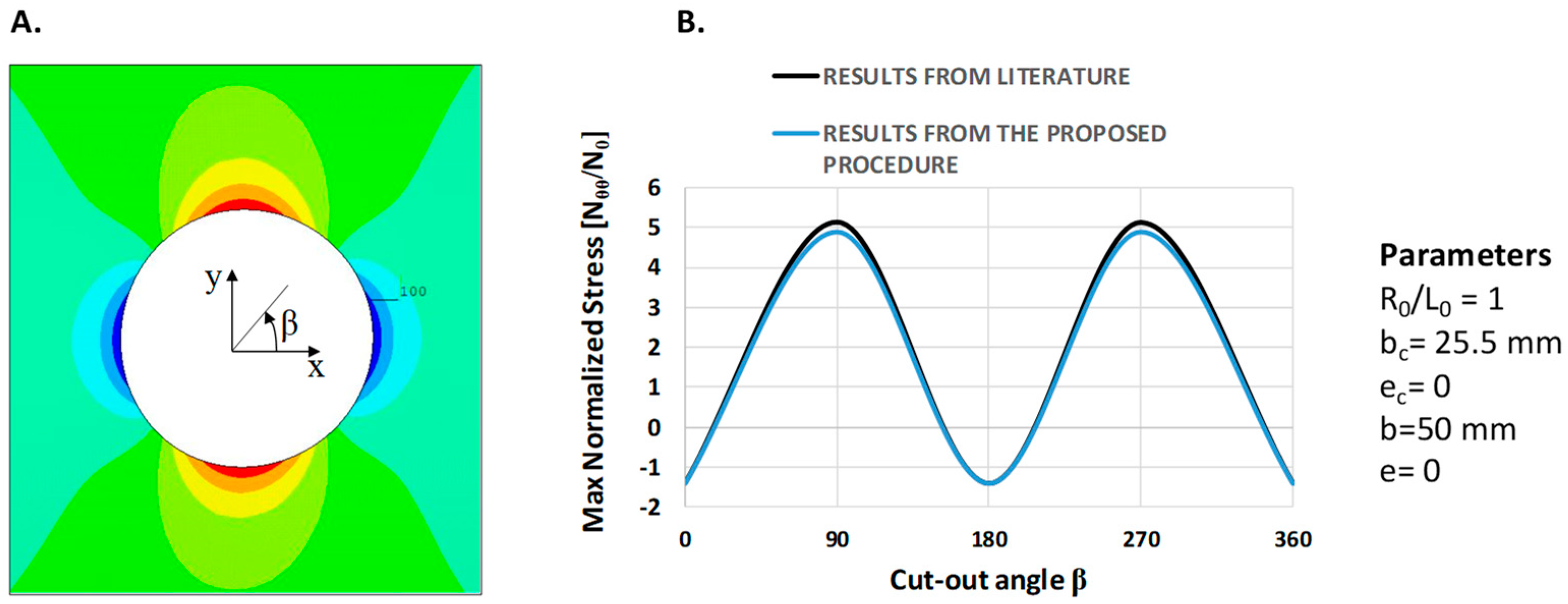
In the present paper, the effect of geometrical parameters’ and loading conditions’ variation on the forces’ distribution have been analyzed in Carbon Fiber Reinforced Plastic (CFRP) thin-walled cylindrical shell structures. A numerical–analytical procedure has been implemented in the ANSYS® Finite Element Method (FEM) code, by means of the Ansys parametric design language (APDL), to build and analyze all possible geometry and cut-out variations, under different loading conditions. Moreover, analytical relationships have been tentatively extrapolated from numerical results, aiming to link the geometrical parameters of the cut-out to the maximum stress near the cut-out. The investigated test case is representative of a fuselage barrel, including windows and/or the passenger door. Indeed, the proposed approach is faster with respect to traditional finite element analyses, usually employed to study the stress field induced by cut-out in cylindrical structures. Hence, it is particularly suitable in the frame of preliminary design stages coupled with optimization procedures, where fast approaches are desirable over more complex, detailed, and time-consuming linear and nonlinear approaches. Hence, the proposed method has been validated by means of comparison with linear FEM numerical approaches, neglecting, at this stage, the complexities and uncertainties resulting from experimental tests. Indeed, in subsequent more detailed design stages, comparison with experimental data will be mandatory.

2. Geometrical Model

The thin-walled shell cylinder, made of fiber-reinforced composite materials, with an elliptical cut-out located in the middle of the structure, as shown in Figure 1, has been analyzed in this paper.
Cylinders’ and cut-outs’ size and eccentricity variations have been studied in this work by means of a sensitivity study. The inclination angle of the elliptical hole, with respect to the cylinder axis, has been considered as a variable parameter, as shown in Figure 2.
The cylinder and cut-out semiminor axis length values can be calculated according to Equations (1) and (2):
b = a 1 e 2
b c = a c 1 e c 2
Basically, the geometrical variables considered in the sensitivity analysis are:
  • The radius of the cylinder (considering a zero value of the eccentricity);
  • The eccentricity of the cylinder;
  • The semiminor axis of the elliptical cut-out;
  • The eccentricity of the elliptical cut-out;
  • The cut-out inclination angle.
A cylinder length (L) of 356 mm was considered, and a quasi-isotropic stacking sequence [+45°/−45°/90°/0°2/90°/−45°/45], with a ply thickness of 0.14 mm, was selected for the computations. The mechanical properties of the used fiber-reinforced material are listed in Table 1.

3. Finite Element Model

The finite element model was built in the ANSYS® FEM environment using a subroutine written in the Ansys parametric design language (APDL). Indeed, a routine has been created able to generate all the possible configurations of the cylindrical shell with an elliptical cut-out, analyzed in this framework, by easily changing the geometrical parameters, such as eccentricity and semiminor axis length. The model was discretized by means of the Ansys® shell layered elements SHELL281 with eight nodes and six degrees of freedom at each node (translations in the x, y, and z axes, and rotations about the x, y, and z axes). Different mesh sizes were adopted to try to reduce the computational effort, preserving, at the same time, the needed accuracy in the cut-out region. In more detail, the optimized element size was found by means of a mesh sensitivity analysis and kept constant in the area with the highest element density, without taking into account the geometrical parameters variations. The model consists of 26,747 shell elements, with a size of about 6 × 6 mm in the area characterized by a coarse mesh, and a size of about 1 × 1 mm in the cut-out region. Figure 3 shows the Finite Element (FE) model, with the detail of the refined mesh in the hole’s area.
Tensile, flexural, and torsional loads have been considered in this study. The boundary conditions’ schematic representations are shown in the following Section 4.1, Section 4.2 and Section 4.3. Linear analyses have been performed in order to assess the effect of the geometrical parameters on the stress concentration near the cut-out, neglecting the nonlinear phenomena. Table 2 lists the geometrical parameters values’ ranges adopted throughout the analyses.

First-order Shell Deformation Theory

The element SHELL281 is well-suited for linear layered applications. In Figure 4a, the geometry, node locations, and the coordinate system for this element are shown. The accuracy in modeling composite shells is governed by the first-order shear deformation theory, usually referred to as Mindlin–Reissner shell theory [18,19,20].
According to Figure 4a,b, let us assume that vector P ¯ represents the location of a shell arbitrary point in the initial state (point B in Figure 4b), and vector Q ¯ is the location of such point in the deformed state. The location of the point A (mid-surface of the shell) is represented by vectors P and Q, respectively, in the initial state and in the deformed state. Normal curvilinear coordinates ξi = [ξα, ξ3] at the point A, in the initial state, are definite by the righthanded triad of the base vectors [aα, a3]. The unit vector a3 is perpendicular to the mid-surface of the shell. Consequently:
P ¯ ( ξ i ) = P ( ξ α ) + ξ α a 3 .
Equally, curvilinear coordinates in the deformed state are definite by [Aα, A3]. Here, the vector A3 may not be normal to the mid-surface of shell. In Equation (4), the vector Q is expanded in Taylor’s series, with respect to coordinate ξ3, normal to the mid-surface of shell.
Q ¯ ( ξ i ) = Q ( ξ α ) + ξ α Q · a 3 + L ,
where Q characterizes the strains’ gradient with respect to coordinate ξ3. The displacements of vectors u and u ¯ , which represent the displacement of the points A and B respectively, are given by Equation (5).
Q ¯ = P ¯ + u ¯    Q = P + u
According to Equations (3–5), the displacement of the arbitrary point B of the shell, for the first-order approximation, can be expressed as in Equation (6), where φ is the rotation vector at the mid-surface, defined by Equation (7).
u ¯ ( ξ α ) = u ( ξ α ) + ξ 3 φ ( ξ α )
φ ( ξ α ) = A 3 ( ξ α ) a 3 ( ξ α )   with   A 3 = G · a 3
The field of displacements, written in terms of Δ u ¯ a , which is the nodal incremental vector, is expressed by Equation (8)
Δ u ¯ ( ξ a ) = a = 1 8 N a ( ξ a ) [ I 3 x 3 ξ 3 h a 2 H a ] Δ u ¯ a ,
where Δ u ¯ a = { Δ u 1 a , Δ u 2 a , Δ u 3 a , Δ ϕ 1 a , Δ ϕ 2 a , Δ ϕ 3 a } and Ha is the rotational matrix of the normal vector at node a, described in Equation (9).
H a = h a T R a ϕ a T A
According to Equation (9), T R a is the transformation matrix between the initial and the deformed shell normal. It can be expressed in terms of finite rotations ϕ1, ϕ2, and ϕ3 as in Equation (10). The terms ϕa and TA are described, respectively, in Equations (11) and (12).
T R a = [ cos ϕ 2 cos ϕ 3 cos ϕ 2 sin ϕ 3 sin ϕ 2 cos ϕ 1 sin ϕ 3 + sin ϕ 1 sin ϕ 2 cos ϕ 3 cos ϕ 1 cos ϕ 3 sin ϕ 1 sin ϕ 2 sin ϕ 3 sin ϕ 1 cos ϕ 2 sin ϕ 1 sin ϕ 3 cos ϕ 1 sin ϕ 2 cos ϕ 3 sin ϕ 1 cos ϕ 3 + cos ϕ 1 sin ϕ 2 sin ϕ 3 cos ϕ 1 cos ϕ 2 ]
ϕ a = [ 0 a 3 a a 2 a a 3 a 0 a 1 a a 2 a a 1 a 0 ]
T A = [ cos ϕ 2 cos ϕ 3 sin ϕ 3 0 cos ϕ 2 sin ϕ 3 cos ϕ 3 0 sin ϕ 2 0 1 ]
The linear strain parts can be described as in Equation (13).
Δ E m = B m Δ u ¯    Δ E b = ξ 3 B b Δ u ¯    Δ E s = B s Δ u ¯

4. Results

In this section, the numerical results, in terms of maximum attained stress as a function of the cylinder radius and the cut-out eccentricity, are shown for each geometrical configuration and loading conditions. From the numerical results, empirical relationships, relating the geometrical parameters to the maximum stress near the hole was tentatively extrapolated.

4.1. Tensile Loading Condition

Firstly, the structural behavior of the cylinder was studied under tensile loading condition by clamping one edge and by applying a unit traction displacement to the opposite one, as schematically shown in Figure 5.
A first set of analyses was performed under the hypothesis of zero eccentricity for the cylinder and the cut-out (a = b; ac = bc). In Figure 6, the maximum stress near the cut-out is displayed as a function of the cylinder radius. Different configurations, with different cut-out radius (bc), were analyzed. The stress value was normalized with respect to the applied load (reaction to the unit traction displacement). According to Figure 6, the maximum stress value near the cut-out decreases as the radius of the shell cylinder increases, as expected. On the other hand, a significant growth in the maximum stress value near the hole is observed by increasing the cut-out size.
Then, additional analyses were performed with variation of the cylinder and cut-out eccentricity. Figure 7 shows the maximum tension near the cut-out as a function of the cut-out eccentricity for a circular cylinder. Different curves, obtained by varying the inclination of the hole, for a fixed cylinder radius, are presented. The results showed that the maximum stress experiences a slight increase as the cut-out eccentricity growth, for ϕ = 0° and ϕ = 30°, while a maximum stress decrease was found for ϕ = 60° and ϕ = 90°. As expected, the lower stress was found when the cut-out inclination is 90° (semiminor axis aligned with the loading direction).
The maximum stress variation as a function of the cylinder eccentricity, for different circular cut-out size, is represented in Figure 8, according to which, the effect of the cylinder eccentricity on the maximum stress value is negligible for a given cut-out size.
As an example, in Figure 9, the deformed shape with the displacement magnitude contour plot for one of the investigated configurations is reported.

4.2. Bending Loading Condition

The structural behavior of the cylinder was then studied under a bending loading condition, as schematically shown in Figure 10. As for the previous loading condition, a circular cylinder and cut-out were firstly considered to investigate the influence of cylinder and cut-out size on the structural behavior, then the eccentricity’s effects were studied. In Figure 11a, the maximum stress near the cut-out was plotted as a function of the cylinder shell radius, for different values of the cut-out semiminor axis (bc). As observed for the tensile loading condition, the maximum stress value near the cut-out decreases as the radius of the cylinder grows. On the other hand, cut-out size (bc) variations do not significantly influence the maximum stress trend. It is interesting to observe that by increasing the hole size, an increase of the maximum tension is found up to a certain cut-out’s semiminor axis value (bc = 30 mm); beyond this value, a decrease is observed. Figure 11b shows the trend of the maximum stress for different cut-out eccentricity variations. It has been found that for a 0° value of the hole’s inclination angle, the effect of the cut-out’s eccentricity on the maximum stress is substantially zero. However, as for the previous loading condition, changing the inclination angle from 0°, an increase or decrease in the maximum stress value can be observed depending on the inclination angle itself.
The effect of the cylinder eccentricity on the maximum stress, for different cut-out semiminor axis values (bc), has not been reported for the sake of brevity, it being negligible. As an example, in Figure 12, a detail of the cut-out region’s deformed shape, with the displacement magnitude contour plot, is plotted for one of the considered configurations.

4.3. Torsional Loading Condition

Finally, the shell cylinder was subjected to torsional loading conditions, as schematically represented in Figure 13. Once again, the circular cylinder and cut-out were firstly considered to investigate the influence of cylinder and cut-out size on the structural behavior, then the eccentricity’s effects were studied. The maximum stress, in proximity to the cut-out, versus the cylinder radius, for different values of the cut-out radius (bc), is presented in Figure 14a. As expected, the maximum stress near the hole experiences a reduction as the cylinder radius increases. The same trend as the one found for the bending loading condition has been observed; hence, the same considerations apply.
According to Figure 14b, which shows the max normalized stress versus cut-out eccentricity, an increase of the hole’s eccentricity leads, basically, to a decrease of the maximum stress, which strongly depends on the cut-out inclination angle.
As an example, in Figure 15, the displacements magnitude contour plot near the cut-out for torsional loading conditions is presented.

4.4. Bending-Torsion Loading Condition

Further simulations considering combined loading conditions, such as coupled bending-torsion load were performed. Figure 16 shows the maximum stress, in proximity to the cut-out, versus the cylinder radius, for different values of the cut-out radius (bc), considering the zero eccentricity of the cylinder and the cut-out. As expected, the maximum stress value decreases as the radius of the shell cylinder increases. Moreover, an increase in the maximum stress value near the hole is observed by increasing the cut-out size.
The results, in terms of maximum normalized stress, were found less critical than the previous considered loading conditions. For such a reason, the effect of the cut-out eccentricity on the maximum stress, for different inclination angles, has not been reported for the sake of brevity.

4.5. Linear Buckling Analysis

The buckling behavior of the cylinder was studied under compressive loading condition by clamping one edge and by applying a unit compressive displacement to the opposite one, as schematically shown in Figure 17.
A first set of simulations was carried out considering zero eccentricity for the cylinder and the cut-out (a = b; ac = bc). In Figure 18a, the buckling load was plotted as a function of the cylinder radius. Different configurations, with a different cut-out radius (bc), were considered. The buckling load has been normalized with respect to the buckling load of a cylinder with the same geometrical dimensions, but without cut-outs. According to Figure 18a, the buckling load growths as the radius of the shell cylinder is increased. On the other hand, a significant decrease in the buckling load is observed by increasing the hole size.
According to Figure 18b, which shows the normalized buckling load versus cut-out eccentricity, an increase of the hole’ eccentricity leads, basically, to a slight increase of the buckling load, that depends on the cut-out inclination angle. However, the buckling load variation can be considered negligible.
As an example, in Figure 19, the out-of-plane displacement contour plot near the cut-out for compressive loading conditions, is presented.
Additionally, the buckling behavior under bending loading conditions (Figure 10) was analyzed. In Figure 20a, the normalized buckling load is displayed as a function of the cylinder radius, while in Figure 20b, the buckling load versus the cut-out eccentricity is reported. It was found that the effect of the cut-out eccentricity on the buckling load value is negligible, for a given cut-out inclination. Moreover, a slight variation of the buckling load can be observed when varying the cylinder radius, for a given cut-out size.

4.6. Unified Analytical Formulation

Taking into account all the performed analyses for the analyzed single loading conditions, such as tension, bending, and torsion, an attempt to extrapolate an empirical relationship was made. The basic idea was to link the variation of the geometric parameters to the maximum tension value near the cut-out, with the aim to perform the initial dimensioning of the thin-walled cylindrical structures and of the cut-out, without the need of finite element calculations. The shell cylinder eccentricity (e) was excluded, since the effects on maximum stress near the cut-out were found to be negligible.
The relationship, derived by means of a second-order polynomial model for four explanatory variables, is reported in Equation (14), where x 1 = e c , x 2 = b c , x 3 = R 0 L 0 and x 4 = ϕ .
M a x S t r e s s ( x 1 , x 2 , x 3 , x 4 ) = c 1 x 1 2 + c 2 x 2 2 + c 3 x 3 2 + c 4 x 4 2 + c 5 x 1 + c 6 x 2 + + c 7 x 3 + c 8 x 4 + c 9 x 1 x 2 + c 10 x 1 x 3 + c 11 x 1 x 4 + c 12 x 2 x 3 + c 13 x 2 x 4 + c 14 x 3 x 4 + c 15 x 1 x 2 x 3 + + c 16 x 1 x 3 x 4 + c 17 x 1 x 2 x 4 + c 18 x 2 x 3 x 4 + c 19 x 1 x 2 x 3 x 4 + c 20
The cn (n = 1, … ,20) constants’ values, reported in Table 3, for each loading condition, were evaluated by means of a MATLAB routine.
Additionally, an empirical relationship, derived by second-order polynomial regression and described in Equation (15), was extrapolated to link the variation of the geometric parameters to the buckling load under compressive loading conditions. The cut-out eccentricity and the inclination angle was found to be irrelevant on the buckling load; for such a reason, they were neglected in the formulas. According to Equation (5), x = R 0 L 0 and y = b c .
B u c k l i n g L o a d ( x , y ) = p 0 + p 1 x + p 2 y + p 3 x 2 + p 4 x y + p 5 y 2
The pn (n = 0, …, 5) constants are listed in Table 4.

4.7. Validation

Additional geometrical parameters’ values, not included in Table 2, were used to validate the derived analytical formulation. Indeed, three numerical simulations, considering tensile, bending, and torsional loads, were performed. The obtained numerical maximum stresses, normalized with respect to the applied load, were compared with the ones obtained from the derived analytical formulations. The geometrical parameters, adopted in the frame of the validation analyses, are introduced in Table 5.
From the numerical analyses, the location which experiences the max normalized stress is identified, and the corresponding stress value is compared to the one resulting from the analytical procedure. The numerical–analytical results comparisons are listed in Table 6, where a maximum percentage error of 1.8% can be pointed out. Hence, this analytical relationship could be significantly useful in the preliminary design phase, when the hole size and shape need to be defined and its influence on the structural performance of the thin-walled components needs to be evaluated.
Furthermore, a linear buckling simulation, considering compressive loading condition, was performed. The obtained numerical buckling load was compared with the ones obtained from the derived analytical formulation. The numerical–analytical result comparison is reported in Table 7, where a percentage error of 0.7% can be observed.
In order to verify the proposed procedure, a comparison against the numerical results from Reference [21] is presented in Figure 21. A quasi-isotropic circular cylindrical shell with circular cut-out, subjected to a uniform tension load, was considered (geometrical parameters are described in Figure 21B) The max stress, normalized by the applied uniform stress resultant, as a function of the position around the cut-out (indicated by the cutout angle β), is shown in Figure 21B. Contour plot of the stress around the cut-out is displayed in Figure 21A; the highest stress-resultant concentration is Nθθ(90°)/N0 = 4.9, measured from the center of the cut-out.

5. Conclusive Remarks

In this work, thin-walled cylindrical shell structures with elliptical cut-outs were investigated. A numerical tool, written in Ansys parametric design language and able to generate different geometrical configurations, was developed and adopted for numerical computations. Indeed, sizes and shapes of the shell cylinder and the cut-out were combined in a sensitivity analysis to study all the possible configurations, choosing among ranges of geometrical parameters values, to assess the dependence of the geometry on the stress distribution near the cut-out. The effect of the cylinder eccentricity on the maximum stress value was found to be negligible, while an increase of the cut-out eccentricity was found to lead, basically, to a reduction of the maximum attained stress. Moreover, for circular cylinders and circular cut-outs, the maximum attained stress near the hole was found to decrease by increasing the cylinder radius for all the loading conditions. A significant impact on the stress distribution was given by the hole inclination angle with respect to the cylinder axis. Indeed, a substantial increase or decrease in the maximum stress was observed depending on the inclination angle itself. An attempt was made to extrapolate an analytical relation, from the obtained numerical results, which is able to describe the dependence of maximum stress near the hole on the geometrical parameters analyzed in the frame the activity presented in this paper. This analytical relation, which has been preliminary validated in the frame of this activity, proved to be fast and very low computationally demanding, compared to the traditional procedure, such as the finite element approach. These fast approaches are very useful in the framework of preliminary design and/or optimization stages when cut-out geometry needs to be defined and the influence of cut-outs on the structural behavior of thin-walled structures needs to be preliminary assessed before the detailed dimensioning design stage. Finally, comparison against numerical results from literature was proposed. The results in terms of maximum stress, normalized by the applied uniform stress resultant, as a function of the position around the cut-out were found to be in excellent agreement with the ones from the literature, proving the effectiveness of the proposed numerical–analytical approach. Linear buckling analyses were performed, by varying sizes and shapes of the shell cylinder and the cut-out, to assess the dependence of the geometry on the buckling load of thin-walled shell cylinders with cut-outs. A unified analytical formulation for coupled loading conditions, able to take into account the percentage of the individual loads, will be implemented in future studies.

Author Contributions

All authors contributed equally to this work.

Funding

This research received no external funding.

Conflicts of Interest

The authors declare no conflict of interest.

References

  1. Sellitto, A.; Riccio, A.; Russo, A.; Zarrelli, M.; Toscano, C.; Lopresto, V. Compressive behaviour of a damaged omega stiffened panel: Damage detection and numerical analysis. Compos. Struct. 2019, 209, 300–316. [Google Scholar] [CrossRef]
  2. Riccio, A.; Sellitto, A.; Saputo, S.; Russo, A.; Zarrelli, M.; Lopresto, V. Modelling the damage evolution in notched omega stiffened composite panels under compression. Compos. Part B Eng. 2017, 126, 60–71. [Google Scholar] [CrossRef]
  3. Riccio, A.; Sellitto, A.; Saputo, S.; Russo, A.; Antonucci, V.; Ricciardi, M.R.; Zarrelli, M.; Lopresto, V. Large Notch Damage Evolution in Omega Stiffened Composite Panels. Procedia Eng. 2016, 167, 151–159. [Google Scholar] [CrossRef]
  4. Riccio, A.; Di Costanzo, C.; Di Gennaro, P.; Sellitto, A.; Raimondo, A. Intra-laminar progressive failure analysis of composite laminates with a large notch damage. Eng. Fail. Anal. 2017, 73, 97–112. [Google Scholar] [CrossRef]
  5. Lurie, A.I. Concentration of Stresses in the Vicinity of an Aperture in the Surface of a Circular Cylinder. Prikl. Mat. Mekh. 1946, 10, 397–406. [Google Scholar]
  6. Lurie, A.I. Statics of Thin-Walled Elastic Shells; State Publishing House of Technical and Theoretical Literature: Moscow, Russia, 1947. [Google Scholar]
  7. Lekkerkerker, J.G. Stress Concentration around Circular Holes in Cylindrical Shells. AIAA J. 1964, 10, 1466–1472. [Google Scholar]
  8. Van Dyke, P. Stresses about a Circular Hole in a Cylindrical Shell. AIAA J. 1965, 3, 1733–1742. [Google Scholar]
  9. Ashmarin, I.A. Stress Concentration around a Circular Opening in an Orthotropic Cylindrical Shell. Prikl. Mekhanika 1966, 2, 44–48. [Google Scholar] [CrossRef]
  10. Murthy, M.V.V.; Rao, K.P.; Rao, A.K. On the Stress Problem of Large Elliptical Cutouts and Cracks in Circular Cylindrical Shells. Int. J. Solids Struct. 1974, 10, 1243–1269. [Google Scholar] [CrossRef]
  11. Guz, A.N.; Chernyshenko, I.S.; Shnerenko, K.I. Stress Concentration near Openings in Composite Shells. Int. Appl. Mech. 2001, 37, 139–181. [Google Scholar] [CrossRef]
  12. Van Tooren, M.J.L.; Van Stijn, I.P.M.; Beukers, A. Curvature Effects on the Stress Distribution in Sandwich Cylinders with a Circular Cut-out. Compos. Part A 2002, 3, 1557–1572. [Google Scholar] [CrossRef]
  13. Tennyson, R.C. The Effects of Unreinforced Circular Cutouts on the Buckling of Circular Cylindrical Shells under Axial Compression. ASME J. Eng. Ind. 1968, 90, 541–546. [Google Scholar] [CrossRef]
  14. Pierce, D.N.; Chou, S.I. Stresses Around Elliptical Holes in Circular Cylindrical Shells. Exp. Mech. 1973, 13, 487–492. [Google Scholar] [CrossRef]
  15. Liang, C.; Hsu, C.; Chen, W. Curvature Effect on Stress Concentrations around Circular Hole in Opened Shallow Cylindrical Shell under External Pressure. Int. J. Press. Vessel. Pip. 1998, 75, 749–763. [Google Scholar] [CrossRef]
  16. Nguyen, D.H.; Wang, H. Multi-Scale Analyses of Three Dimensional Woven Composite 3D Shell with a Cut Out Circle. Appl. Compos. Mater. 2019, 26, 339–356. [Google Scholar] [CrossRef]
  17. Yazici, M.; Özcan, R.; Ülkü, S.; Okur, I. Buckling of composite plates with U-shaped cutouts. J. Compos. Mater. 2003, 37, 2179–2195. [Google Scholar] [CrossRef]
  18. Reissner, E. The Effect of Transverse Shear Deformation on the Bending of Elastic Plates. J. Appl. Mech. 1945, 12, 69–77. [Google Scholar]
  19. Mindlin, R.D. Influence of Rotatory Inertia and Shear on Flexural Motions of Isotropic, Elastic Plates. J. Appl. Mech. 1951, 18, 31–38. [Google Scholar]
  20. Reissner, E. On the Theory of Bending of Elastic Plates. J. Math. Phys. 1944, 23, 184–191. [Google Scholar] [CrossRef]
  21. Oterkus, E.; Madenci, E.; Nemeth, M.P. Stress analysis of composite cylindrical shells with an elliptical cutout. J. Mech. Mater. Struct. 2007, 2, 695–728. [Google Scholar] [CrossRef]
Figure 1. Geometrical model.
Aerospace 06 00052 g001
Figure 2. Variable parameters.
Aerospace 06 00052 g002
Figure 3. Finite element model with cut-out detail.
Aerospace 06 00052 g003
Figure 4. SHELL 281: (a) 8-nodes shell element geometry; (b) first-order shear deformation theory kinematics.
Aerospace 06 00052 g004
Figure 5. Tensile load.
Aerospace 06 00052 g005
Figure 6. Maximum stress vs. cylinder radius–traction load (zero eccentricity condition).
Aerospace 06 00052 g006
Figure 7. Maximum stress vs. cut-out eccentricity–traction load.
Aerospace 06 00052 g007
Figure 8. Maximum stress vs. cylinder eccentricity–traction load.
Aerospace 06 00052 g008
Figure 9. Deformed shape with displacement magnitude contour plot–tensile load, cut-out region.
Aerospace 06 00052 g009
Figure 10. Bending load.
Aerospace 06 00052 g010
Figure 11. Bending load: (a) Maximum stress vs. cylinder radius; (b) maximum stress vs. cut-out eccentricity.
Aerospace 06 00052 g011
Figure 12. Deformed shape with displacement magnitude contour plot–bending load, cut-out region.
Aerospace 06 00052 g012
Figure 13. Torsional load.
Aerospace 06 00052 g013
Figure 14. Torsional load: (a) Maximum stress vs. cylinder radius; (b) maximum stress vs. cut-out eccentricity.
Aerospace 06 00052 g014
Figure 15. Deformed shape with displacement magnitude contour plot–torsional load, cut-out region.
Aerospace 06 00052 g015
Figure 16. Maximum stress vs. Cylinder radius–bending-torsion load (zero eccentricity condition).
Aerospace 06 00052 g016
Figure 17. Compressive load.
Aerospace 06 00052 g017
Figure 18. Compressive load: (a) Buckling load vs. cylinder radius; (b) buckling load vs. cut-out eccentricity.
Aerospace 06 00052 g018
Figure 19. Deformed shape with out-of-plane displacements contour plot–compressive load, cut-out region.
Aerospace 06 00052 g019
Figure 20. Bending load: (a) Buckling load vs. cylinder radius; (b) buckling load vs. cut-out eccentricity.
Aerospace 06 00052 g020
Figure 21. Maximum stress vs. cut-out angle–tension load (zero eccentricity condition).
Aerospace 06 00052 g021
Table 1. CFRP mechanical properties.
ParameterUnit of MeasureValue
E11GPa135
E22GPa13
ν12-0.38
G12GPa6.4
Table 2. Geometrical data of the cylindrical shell configurations.
ParameterSymbolValue
Cylinder radius (e = 0)R0/L00.5–0.75–1–1.25
Cylinder eccentricitye0–0.166–0.333–0.5
Cut-out semiminor axisbc10 mm–20 mm–30 mm–40 mm
Cut-out eccentricityec0–0.166–0.333–0.5
Cut-out inclination angleϕ0°–30°–60°–90°
Table 3. Constant values.
ConstantMax Stress
TractionBendingTorsion
c 1 0.0541181.0386−0.9049
c 2 −0.00021075−0.002581−0.0030235
c 3 0.4342810.4312.622
c 4 2.2118 × 10⁻⁸−7.5549 × 10−50.00010336
c 5 0.42616−1.4326−2.5875
c 6 0.0406780.17670.23742
c 7 −0.74793−25.978−30.206
c 8 0.000640530.0056456−0.010479
c 9 0.00384580.106040.11993
c 10 0.0493410.678432.0817
c 11 −0.0108450.0216060.023188
c 12 −0.017707−0.036045−0.062669
c 13 5.9633 × 10−68.117 × 10−59.6716 × 10⁻⁵
c 14 1.3043 × 10−60.000867090.00072332
c 15 −0.0035319−0.079826−0.089864
c 16 6.1511 × 10⁻⁵−0.015691−0.014884
c 17 −9.2267 × 10⁻⁵−0.0014505−0.001739
c 18 −4.4331 × 10⁻⁶−6.5018 × 10⁻⁵−7.0629 × 10⁻⁵
c 19 7.1732 × 10−50.00113560.0012687
c 20 2.692417.07520.397
Table 4. Constants values, compressive load.
ConstantBuckling Load
p 0 0.9697
p 1 0.4218
p 2 −0.03659
p 3 −0.1457
p 4 0.002061
p 5 0.0003753
Table 5. Geometrical parameters.
ParameterSymbolValue
Cylinder radiusR0/L00.9
Cylinder eccentricitye0
Cut-out semiminor axisbc25
Cut-out eccentricityec0.2
Cut-out inclination angleϕ50°
Table 6. Result comparison.
Tensile LoadBending LoadTorsional Load
NumericalAnalyticalError (%)NumericalAnalyticalError (%)NumericalAnalyticalError (%)
2.881474742.87730.1%4.236674324.31311.8%5.927988415.84451.4%
Table 7. Result comparison.
Compressive Load
NumericalAnalyticalError (%)
0.60150.59750.7%

