1. Introduction
Self-healing materials are becoming more and more attractive as a consequence of the increasing interest in the “damage management” concept, which is being adopted in the maintenance and repair programs of advanced and complex systems such as aircraft and aerospace vehicles. This design strategy is based on the idea that proper control of the damage extent and propagation can reduce human intervention and, in general, increase the reliability and duration of a damaged component. The ability of some materials to autonomously repair damages well with no or limited external intervention responds to these requirements. At present, several polymeric materials have been developed which, under certain conditions, can fully or partially restore their functionality as a consequence of autonomic repair. The mechanisms that lead to the healing process are, however, very diverse for the different polymeric systems and produce varying mending efficiencies [
1,
2,
3,
4,
5].
The material studied in this work is an ethylene-methylacrylate copolymer-based ionomer (Surlyn® 8940 by Du Pont de Nemours), which has demonstrated its remarkable self-healing capabilities when punctured in firearms shootings; thanks to these capabilities, a number of prospected applications in safety and space components have been proposed [
6,
7,
8]. This polymer is intrinsically self-healing, in that the autonomic repair is activated by the damage itself. The healing mechanism is based on the strain and friction energy dissipation, leading to rapid melting of the material during the perforation phase, followed by the hole closure caused by the strain recovery and final material welding and solidification, which occur immediately after puncture, within a fraction of a second [
1,
2,
3,
9,
10,
11,
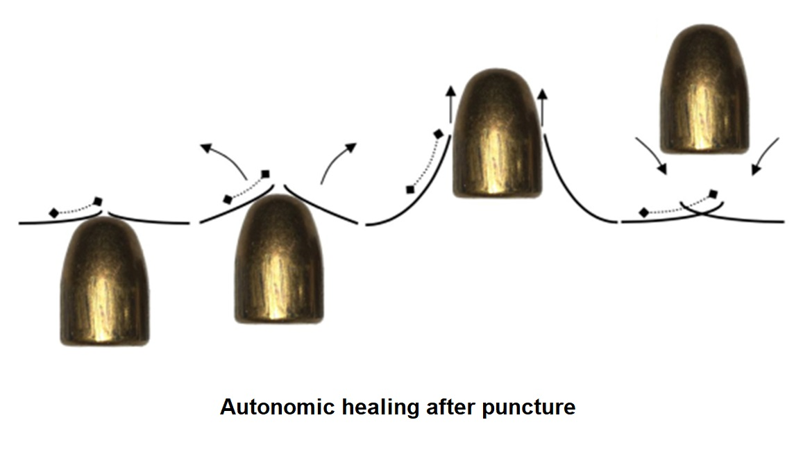
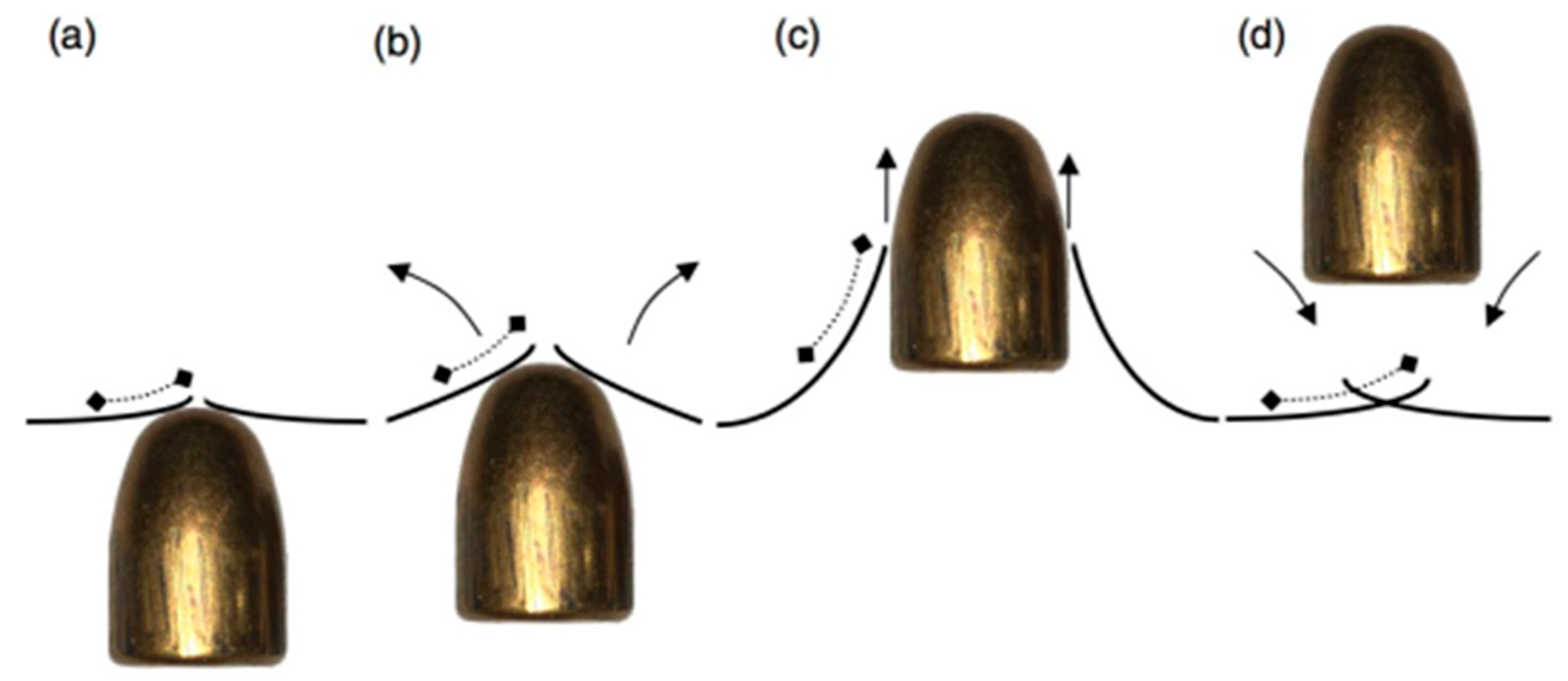
12]. The perforation and healing process is visualized and summarized in
Figure 1: A high-speed projectile hits the sample (a) that rapidly deforms (b). The very high deformation and strain rate accounts for a rapid and consistent increase of temperature in the punctured zone, so that the material melts and breaks (c). Since only a small zone melts, and thanks to the viscoelastic recovery, there is an important strain relief that closes the perforation immediately after the bullet passage, while the hole edges are still molten (d), bringing to the final welding. The ionomeric nature of the polymer possibly enhances the viscoelastic recovery and the retrieval of relevant mechanical performances. While the general mechanism is well recognized, a number of issues regarding the energy contributions involved in the heating and healing, in addition to the influence of the material conditions and bullet characteristics over the whole process remain to be fully interpreted.
In this research, an extensive experimental campaign was carried out in which different tests were performed focusing on aspects that were not fully approached previously, like the polymer aging effects, the role of friction between bullet and perforated panel over energy dissipation and the response to multiple perforations. Moreover, an evaluation of the different energy contributions is presented and discussed in relation to the thermal effects involved in the puncture healing process.
The aging in ionomers involves the formation and evolution of ionomeric clusters formed by the association of polar groups; this is evidenced by the presence of a secondary transition, whose extent is expected to affect the healing efficiency [
1,
2,
4]. Although a number of non-ionomeric polymers also display self-healing behavior, the presence of ionomeric clusters is likely to efficiently contribute to the viscoelastic recovery of the polymer melt and to assist the restoration of the mechanical performances after the autonomic repair [
13]. Since the dynamics of clusters reformation after melting and perforation is quite slow, with stabilization times in the order of weeks, an experimental investigation of the mechanical properties evolution and the puncture healing efficiency with aging was deemed interesting. In addition, repeated shots in the same location, i.e., involving already-healed material, demonstrated the maintenance of the self-mending capacity, yet with a somewhat reduced efficiency.
The role of friction over the energy transfer between the impacting bullet and the perforated panel is still controversial. While the presence of friction is certainly expected to increase the fraction of bullet kinetic energy that is dissipated within the punctured panel, whether friction is fundamental for the healing process is not clear [
14]. In order to evidence the importance of friction in the impact energy dissipation and over the healing process, ballistic tests with the presence of lubricant over the impact area were conducted. The results of tests with lubricated specimens and repeated shots are discussed.
A consistent sensitivity of the EMAA healing capacity on temperature variation has been previously reported for thin films, which is consequent to temperature-dependent mechanical properties and the varying aging rate [
14]. In view of an estimation of the energy contributions involved, in this research, thick panels were impacted at different temperatures, and the damage and healed areas were analyzed. The analysis of energy contributions can follow two distinct, but related approaches; from the mechanical point of view, the bullet energy transferred to the panel during impact induces extensive plastic deformation. A comparison between the energy lost by the bullet during puncture and the deformation energy provides a basis for the analysis of energy contributions leading to the melting of the material. From the thermal point of view, the evaluation of the energy required to raise the temperature of the material at the impact area above the melting temperature can provide confirmation of the melting/welding process and an estimation of the polymer volume involved in healing. The influence of temperature conditions over these aspects was also experimentally investigated and discussed.
With a more applicative view, in order to improve the safety in the design and manufacture of containers for fuels, a potential use of these new materials can be their integration in the tank walls to suppress or reduce liquid spilling in case of punctures or bullet perforations. The focus of this investigation is mainly related to aircraft and helicopter fuel tanks; however, the same concepts and solutions may be applied for the containment of dangerous fluids in general.
Fire and deflagration involving the full tank often start with the leakage of fuel as a consequence of the rupturing of the tank walls; this is then followed by vapor ignition due to electric or friction sparks. On this basis, possible solutions should be directed towards the limitation or prevention of leakages and the suppression of the explosion. Various concepts have been explored over the years, for the inhibition of tanks explosion, including pressurization of the ullage space with inert gas [
15]. Among these, foam and metallic fillers are the most used in military aircraft and helicopters. The coupling of such self-healing polymers as tank walls with cellular fillers can lead to relevant improvements, allowing high impact resistance, repeatable and environmentally stable self-healing capability, lightness, mechanical stiffness and strength.
The integration of self-mending walls and filler made from expanded aluminum foil is expected to enhance the safety of tanks in case of puncture by high-speed objects and limit the fuel loss, thus extending the functioning capability even after damage. In this study, the self-healing capacity of such configurations has been experimentally explored, also considering the effects of bullet diameter/wall thickness and of the presence of internal tank pressure over the healing efficiency.
2. Materials and Methods
The thermoplastic self-healing ionomer used as a tank wall was a copolymer poly(ethylene co-methacrylic acid) neutralized with sodium; it is available as a commercial material with the name of Surlyn® 8940 (from DuPont de Nemours—USA, Wilmington, DE, USA). It contains 5.4% mol. of methacrylic acid groups distributed along the main polyethylene chains; about 30% of the acid groups are neutralized with sodium. The material, received in granular form, was compression molded in a hot-platens press to obtain polymer plates of 130 mm × 130 mm sides, with thicknesses ranging from 1.5 mm to 3 mm, which were employed in subsequent thermal and mechanical tests. The flat plates were aged at room temperature for the prescribed time period before tests. Material aged for more than 30 days was assumed to have reached stable conditions.
The thermo-mechanical behavior of the material was assessed by Differential Scanning Calorimetry (DSC 2920–TA Instruments—New Castle, DE, USA) tests performed at a 10 °C/min heating/cooling rate. Tests at a higher ramp rate (20 °C/min and 30 °C/min) were also performed in the attempt to evidence possible thermal events. Dynamic mechanical tests and complex viscosity measurements were performed with a Rheometrics RDAII torsional rheometer at 1 Hz, in a temperature range between 25 °C and 220 °C. Tensile tests of dog-bone ionomeric specimens were carried out at room temperature and a 5 mm/min crosshead rate (gage length 50 mm, width 10 mm) with an Instron mod. 4302 Dynamometer. Specimens for DMA (dynamic-mechanical analysis) and tensile tests were directly cut from molded plates.
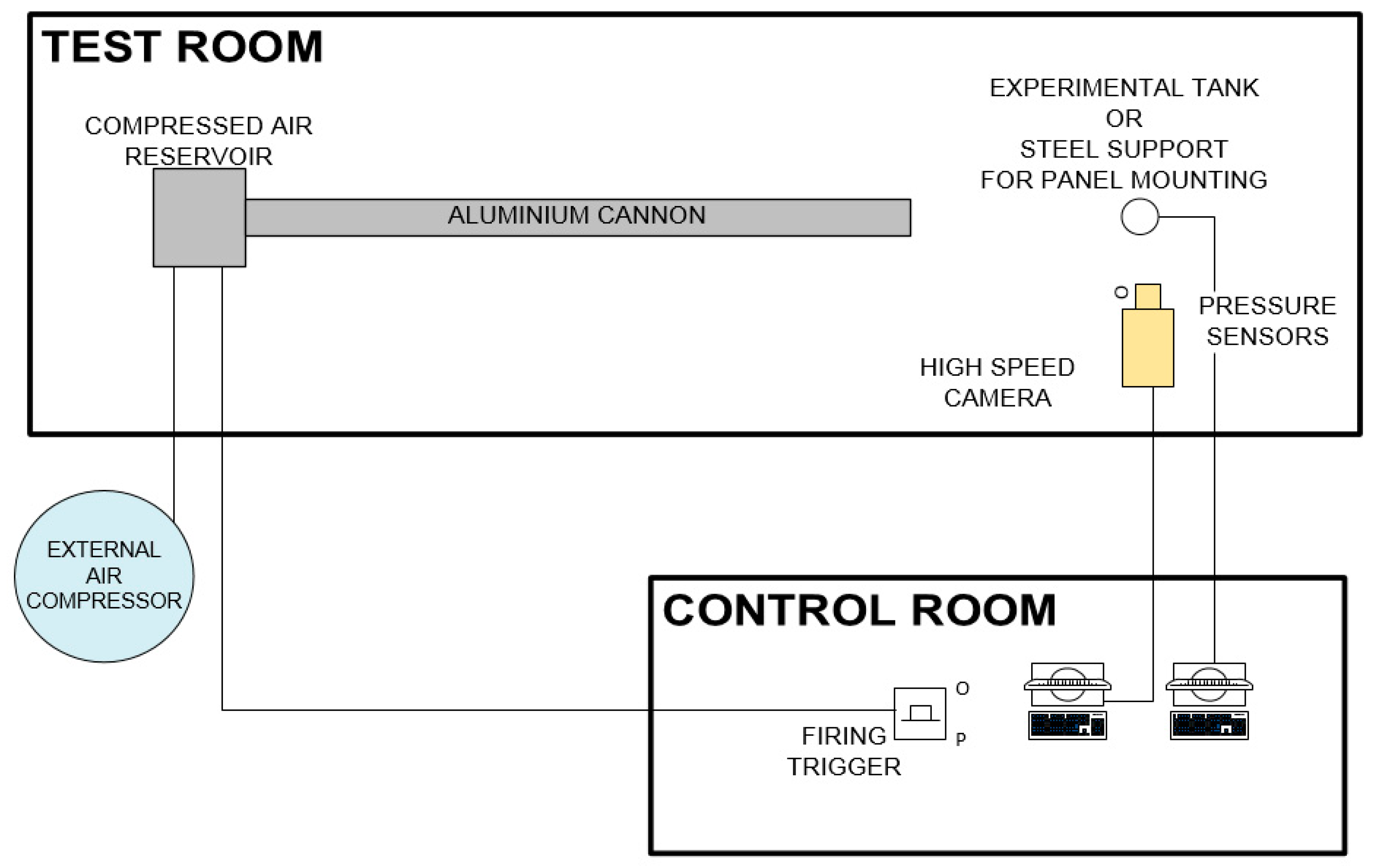
The flat plates used in the ballistic proofs were shot with different bullets at different velocities. The bullets used at low speeds (160 m/s–180 m/s) were steel spheres with a diameter of 9.55 mm (mass = 3.52 g). The speed was measured by means of a high-speed camera. The available shooting facility is composed of an air chamber pressurized at 6.5 bar by an external air compressor and separated from the outside ambient through a 0.075 mm thick metal foil. An electronic switch activates a solenoid which triggers a sharp point toward the metal foil. After the foil puncture, the differential pressure causes the sudden expansion and flow of the compressed air through a long aluminum tube (length 7 m, internal diameter 40 mm, external diameter 70 mm). The air flow launches a high-density polyethylene (HDPE) sabot, which carries the steel sphere inside the aluminum tube until it reaches the end of the barrel; a dissipative aluminum tube absorber and an aluminum stopper block the sabot at the end of the tube, while the steel sphere is projected against the target.
A high-speed Phantom v5.1 camera was employed to measure the projectile velocity prior to and after the impact by recording the time required to cover a short distance. Projectile speeds in the range 150 to 200 m/s are reached dependent on the air reservoir pressure [
16]. In
Figure 2, the schematic of the ballistic test set-up is shown.
The tests at medium velocities (280 m/s–450 m/s) were carried out at the TSN-National Shooting Range in Milan and at the Ballistic Laboratory of the Italian bullet manufacturing company, Fiocchi Munizioni SpA, Lecco, Italy. In this case, the bullets were 9X21 and .45ACP calibers, shot by a Kimber Custom II handgun and a Beretta CX4-Storm Carabine. 9X21 and .45ACP bullets have a rounded impact nose with a diameter of 9.5 mm and 11.5 mm, respectively. The speed was measured by a laser chronograph. For the temperature-controlled tests, the ionomeric panels were kept in thermostatic chambers at temperatures between −40 °C and +70 °C before shooting; the actual temperature at the moment of shooting was checked by a non-contact infrared thermometer.
All shots with flat panels at low and medium velocities, at low and high temperatures, with different bullets, were repeated at least two times.
Leakage tests, imposing a differential pressure on the two sides of the perforated item, were used to detect the presence of non-healed holes and check for the self-healing efficiency. Scanning electron microscopy (SEM TM3000-Hitachi, Tokyo, Japan) analyses, at different magnifications, were used to observe the morphology of the punctured/healed holes and get evidence of the melting and re-solidification features of the material after each ballistic test. Tensile tests after ballistic impacts were carried out with specimens having an impacted zone in the middle of the gage length and results were compared to analogous test data with not impacted specimens.
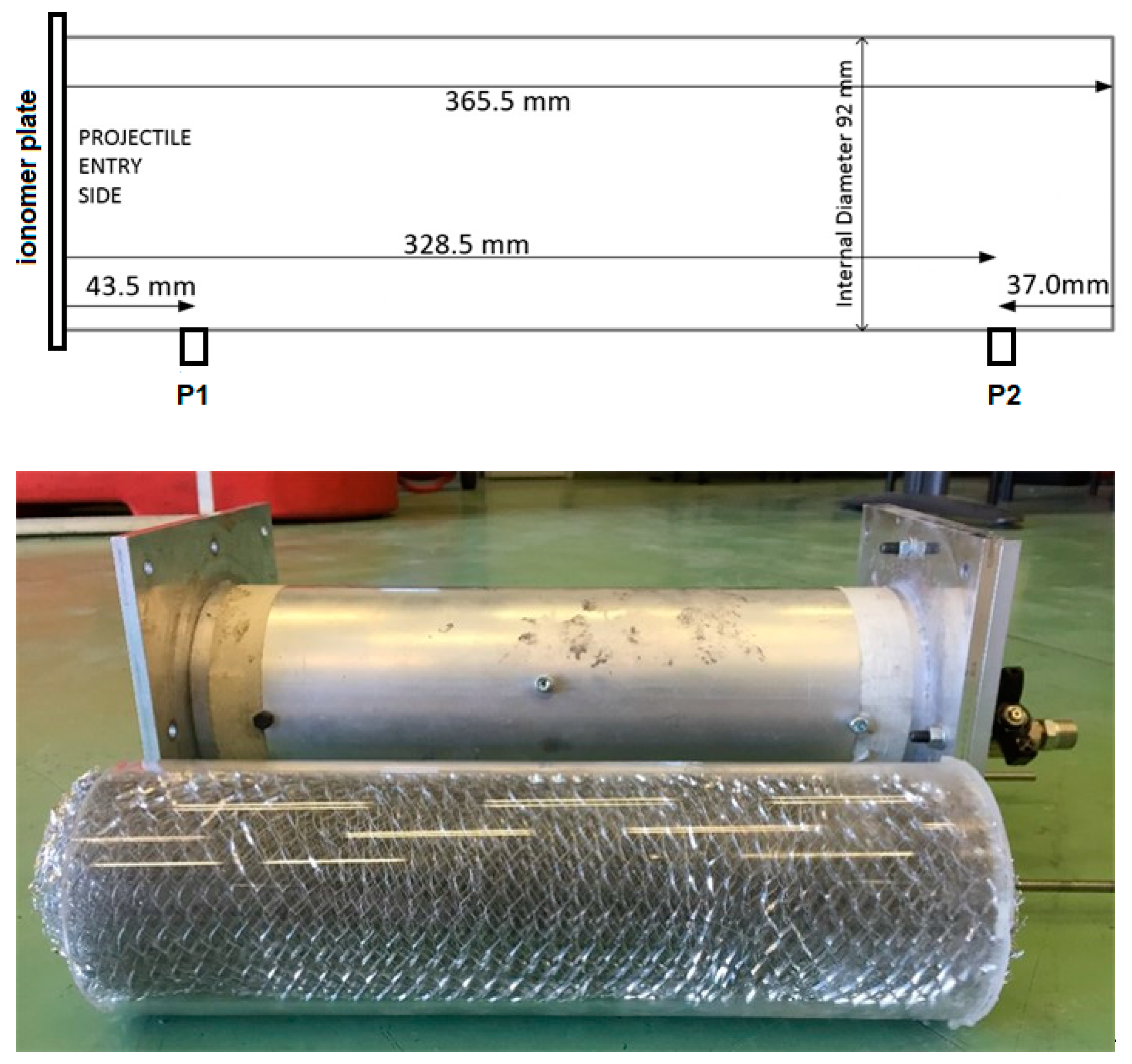
Finally, ballistic tests on a mock-up of the new conceptual solution for fuel tanks were carried out. The tests were conducted using the same air gun as that used in the low-speed ballistic impacts on flat plates. The tank mock-up consisted of a 6064 T6 aluminum alloy tube (92 mm internal diameter, 366 mm length), with flanged ends to fit the ionomer Surlyn® 8940 plates. The tank could be pressurized with water inside and with the presence of the anti-sloshing filler. Pressure sensors were placed in different positions along the tube. A similar tank with a transparent PMMA tube was used for tests requiring internal observation; no pressure sensors and no pressurization option were adopted in this case.
Explosafe
® was used as an anti-sloshing material in the tank; it is made of an aluminum sheet manufactured by slitting and expanding a foil to create hexagonal holes. The average density of Explosafe
® is 30 kg/m
3. It was used both as a single rolled block or as small cylindrical pellets fitting the tank space. Its presence in aircraft fuel tanks is expected to reduce liquid sloshing, to dampen pressure peaks in case of impacts and to slow down fuel spilling in case of perforation, thus providing explosion suppression effects [
17,
18,
19].
Ballistic tests of a simplified model tank were performed using steel balls as projectiles with sizes ranging between 2.35 mm and 16.6 mm (mass between 0.053 g and 18.74 g).
Figure 3 shows the tank mock-up configurations employed.
3. Results and Discussion
3.1. Testing of Single Flat Panels
3.1.1. Aging Effects
In order to investigate how the effects of aging influenced the thermal and mechanical properties of the polymer, five different ionomer molded plates with different time spans were selected: 1, 7, 14, 28, and 42 days. Thermal and mechanical tests were carried out after the selected aging times, either with not impacted specimens or with specimens that were impacted with low-speed steel spheres and which showed healing. For the latter case, specimens for mechanical tests were cut so that the healed area was in the middle of the specimens. It was previously reported [
2,
3,
8,
11,
13] that the healing efficiency increases in correspondence with ionic cluster evolution, reaching stabilization after about 30 days. In our tests, the provided projectile impact speed was above 160 m/s, and all specimens showed full healing. Only when the projectile speed was lower, partial healing or non-perforated panels were observed.
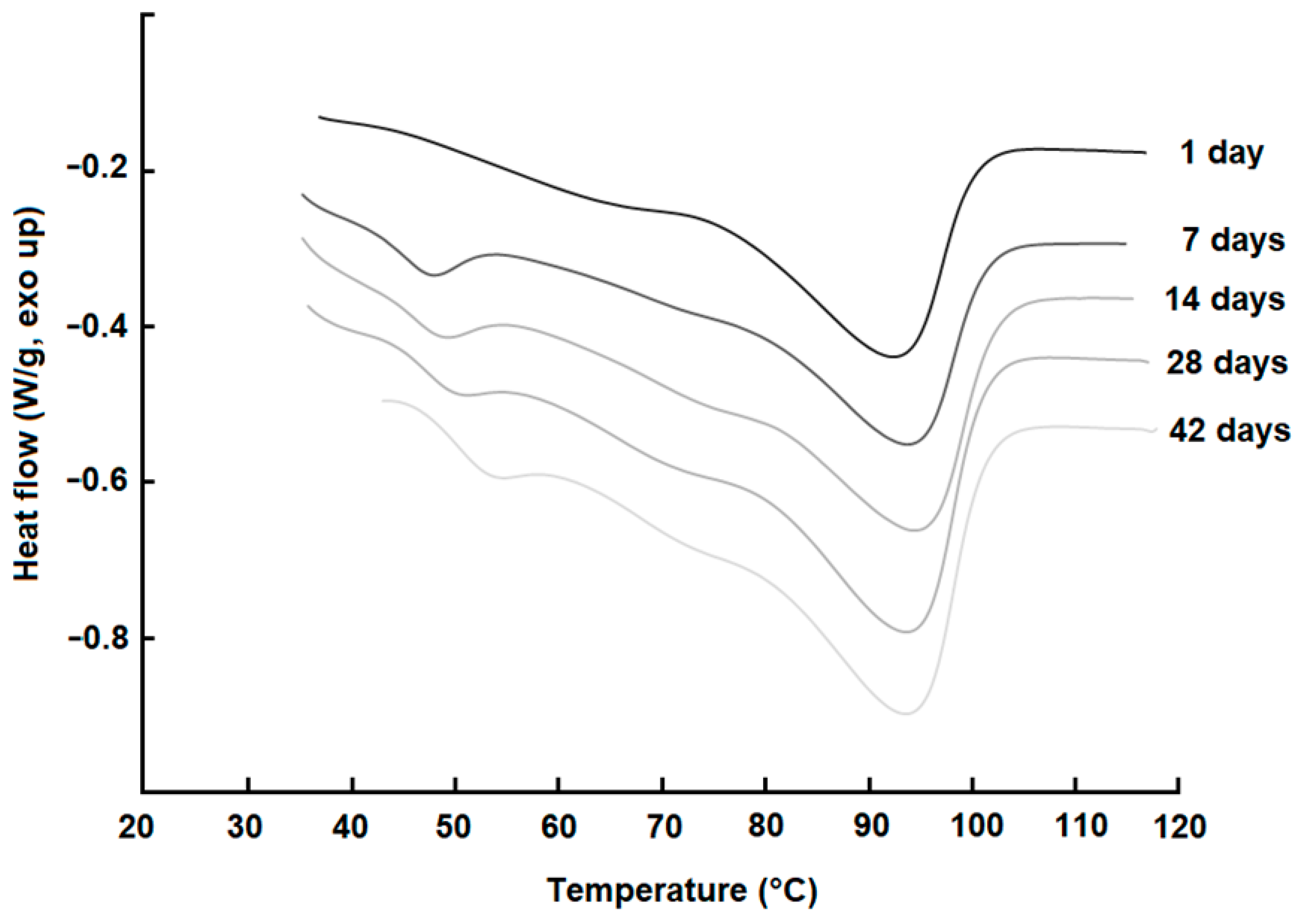
DSC tests show a clear change of the secondary transition temperature,
Ti, between 40 °C and 60 °C and the corresponding heat transfer; the peak, which may be related to the ionic presence, becomes more defined and shifted to higher temperatures with the increasing aging time. According to the tests performed, the secondary transition cannot be detected for a sample aged 1 day which might be due to the low size of the ordered microstructure formations for this aging time, see
Figure 4. The lower peak appears for samples aged for more than 1 day and gets bigger with the aging time, as reported in
Table 1. These results show that aggregates grow so that molecular mobility and a re-organization of the polymer chains is possible during the aging of the material. At about 90 °C, full melting occurs as indicated by the large endothermic peaks; no relevant effect of aging is evidenced over the melting process.
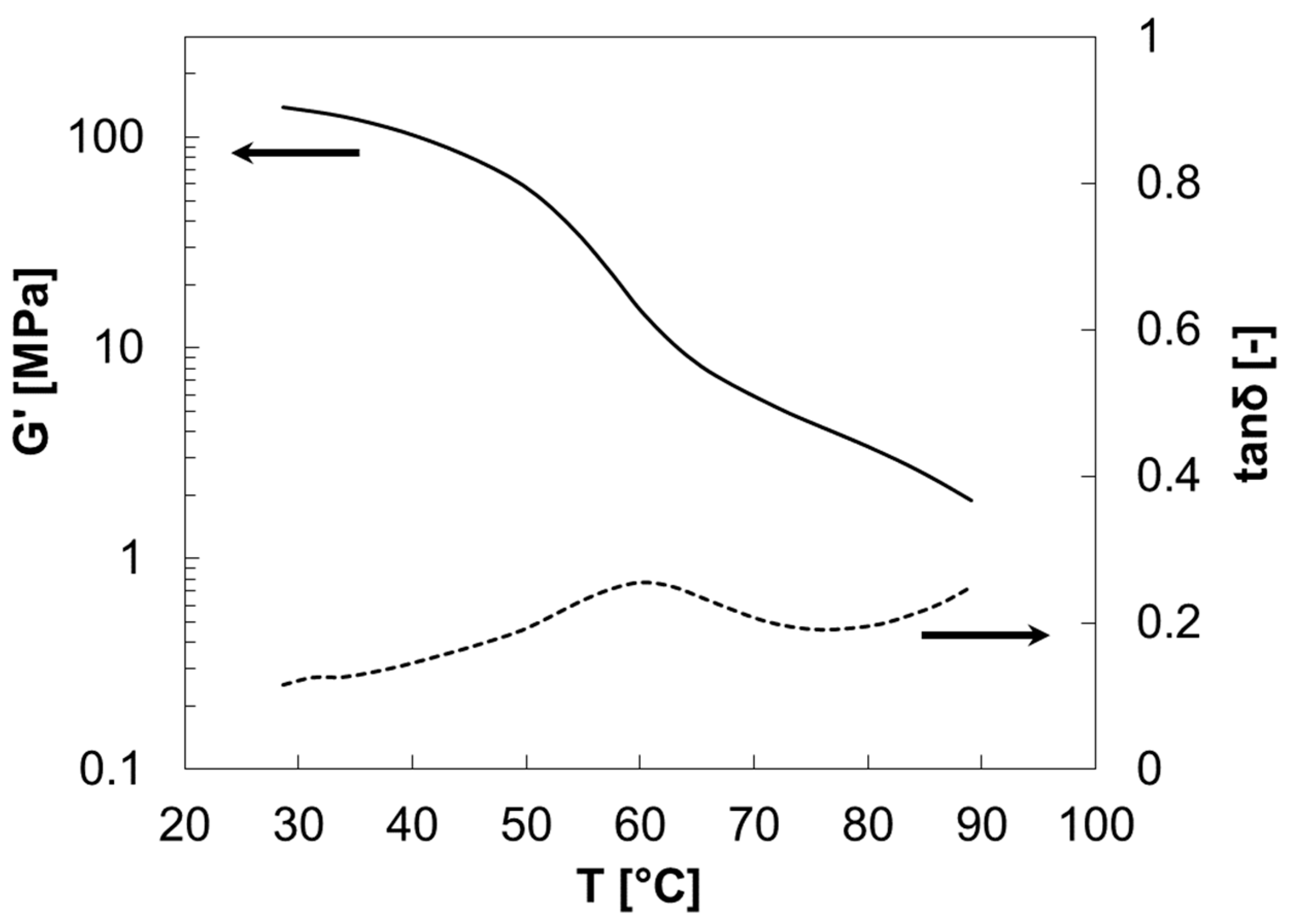
DMA tests confirm these results: A drop of storage modulus, due to the secondary transition, shows that some molecular motion is activated between 40 °C and 70 °C; in this case, evidence of a transition is also shown after the shortest aging time, see
Figure 5.
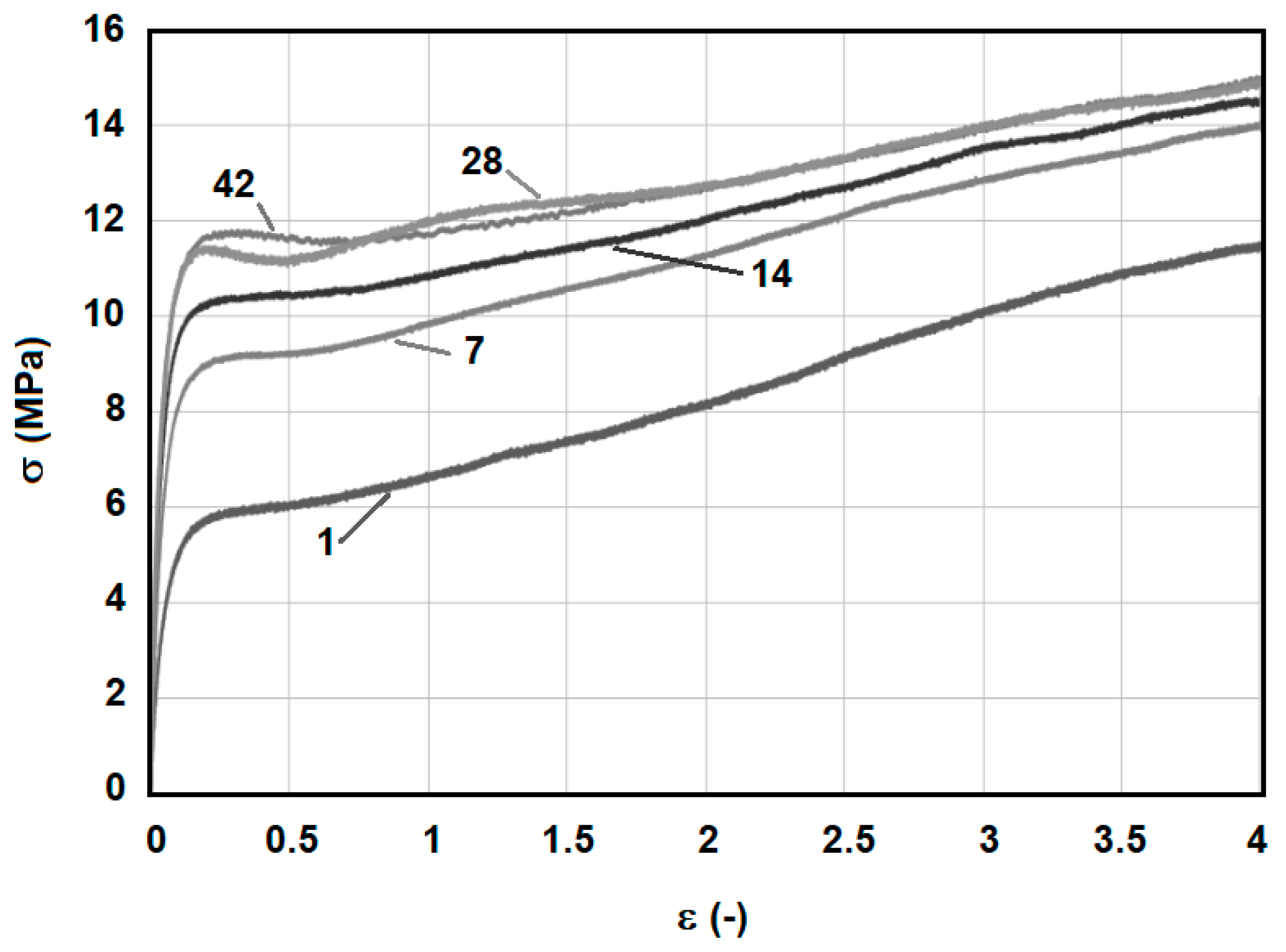
The main results of the tensile tests performed are shown in
Figure 6. An increase of the stiffness and the yield stress with aging time can be noticed. Stabilization occurs after about 30 days. Failure of the specimens cannot be observed at the low strain rate applied due to the limited displacement capability of the testing system. At the crosshead speed of 5 mm/min, failure always occurs for strains exceeding 400%.
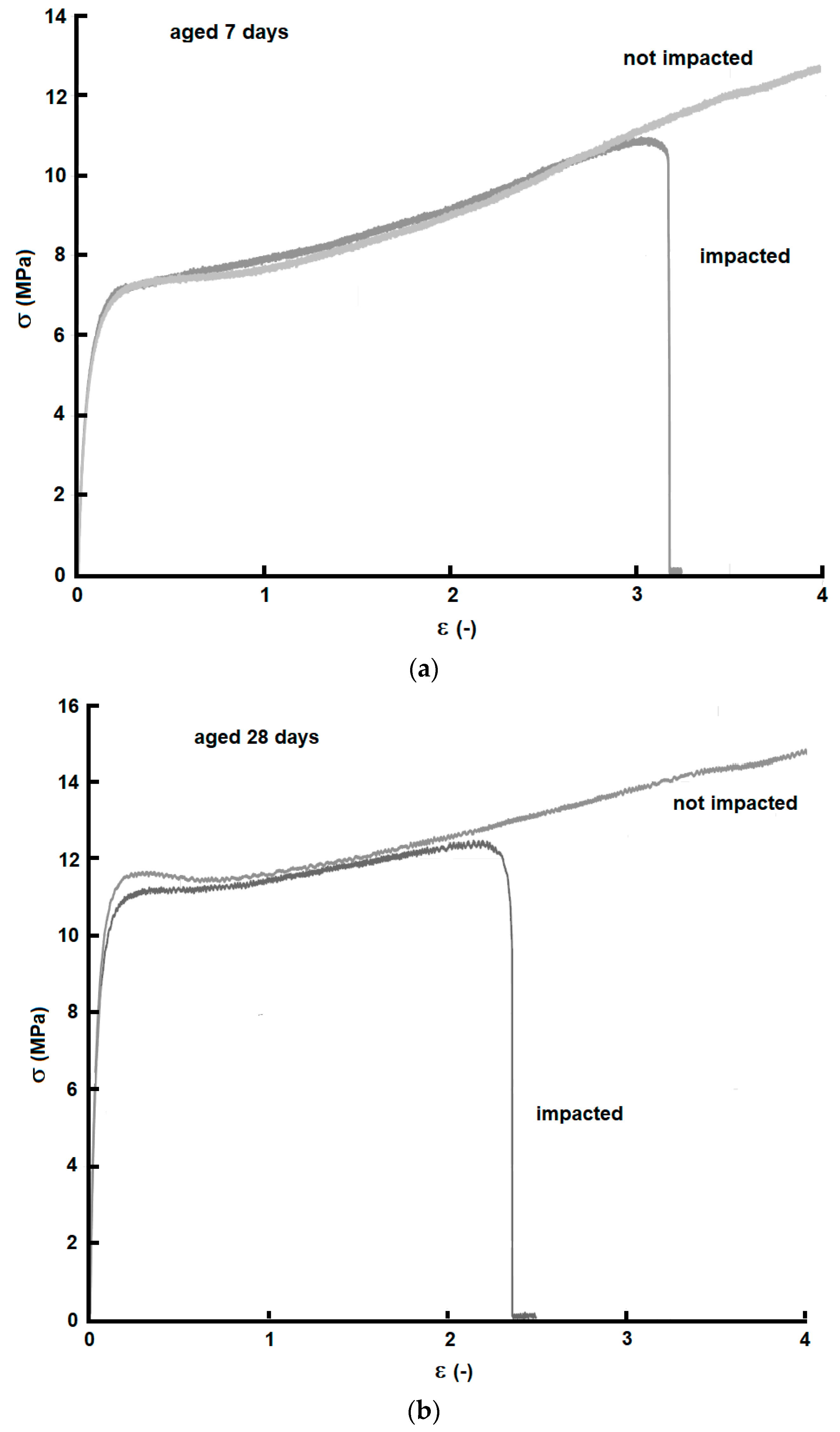
In order to understand how the healing process influences the mechanical behavior of the ionomer, completely healed impacted specimens were tensile tested after the same aging times as the not impacted specimens. It should be noted that the material volume interested by melting and re-welding is a small portion of the total volume of impacted specimens; most of the impacted region, although deformed during impact, is not subjected to an actual phase change. As a matter of fact, the results did indicate an appreciable variation in terms of the yield strength and stiffness. On the other hand, impacted and healed specimens showed a lower elongation and stress at break, which reduced with increasing aging time, but remained quite large and always well above yield values.
Figure 7 reports, as examples, the stress–strain curves recorded in impacted and not impacted specimens after 7 and 28 aging days.
3.1.2. Friction Reduced Tests
In order to investigate the influence of friction in the healing process, shooting tests were conducted, applying a 1 mm thick layer of lubricant grease on the specimens in the impact area. Tests with medium-speed bullets shot by firearms and with low-speed steel spheres launched by an air cannon were performed.
Medium Speed
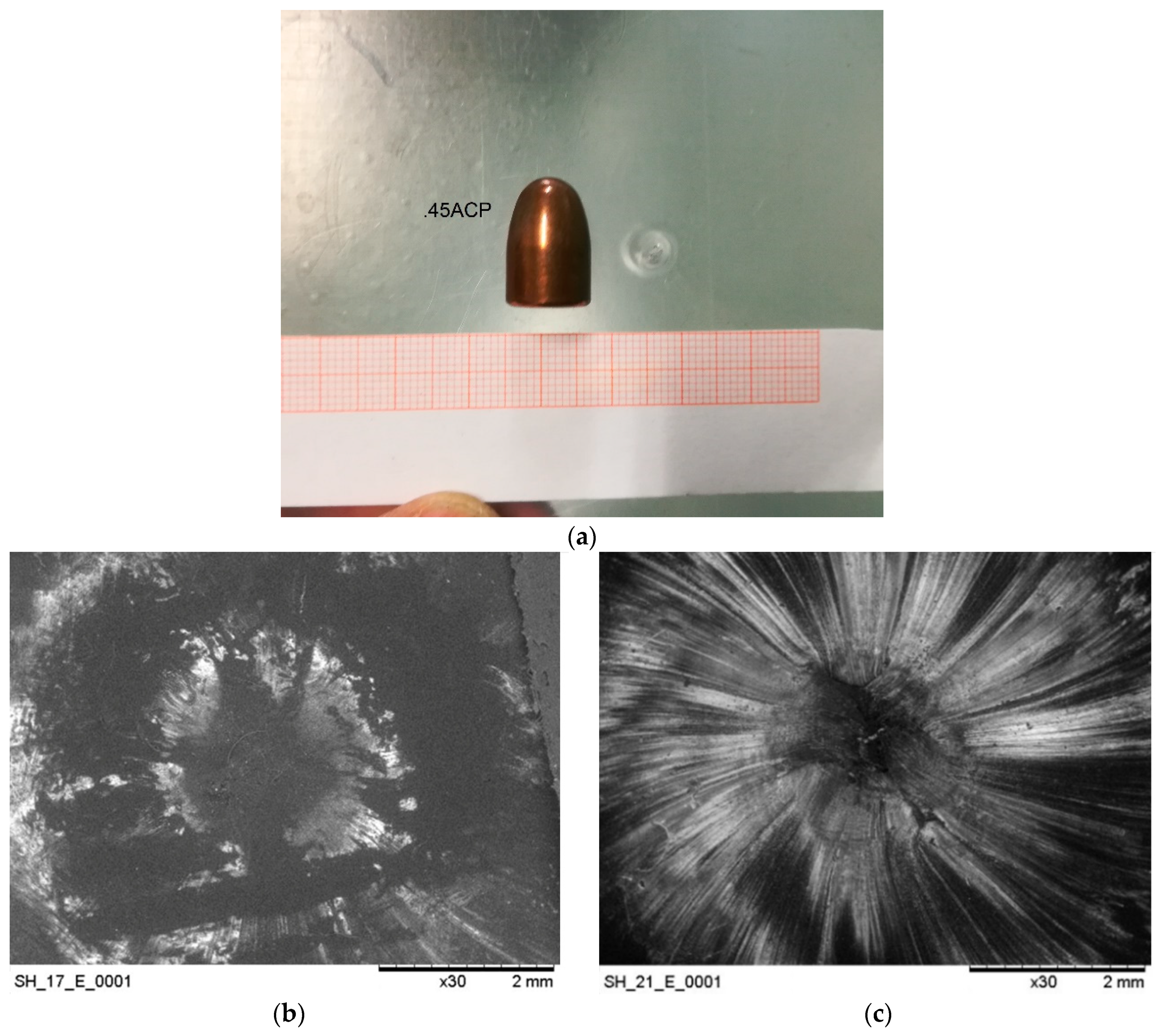
Ballistic tests were carried out using 9 × 21 bullets (diameter 9.03 mm) shot with the rifle. Full healing was obtained in all cases, as confirmed by leakage tests. In
Figure 8a, an example of a healed panel after bullet puncture is shown; SEM images, see
Figure 8b,c, show the difference of bullet passage through ionomer panels in the two situations, i.e., with and without lubricant. In both images, two different circular areas can be distinguished; an internal area, where the material melted, which is much smaller than the bullet diameter and an outer area where most of the viscoelastic deformation occurred with no phase change. It is in the outer area where the main differences can be noticed; the absence of the striations suggests that the lubricant, with its slippery effect, allows the bullet to pass through the ionomer with lower material stretching (low plastic deformation). This observation may be linked to a rapid viscoelastic return and a lower drop of the temperature in the melted area; the consequence of which seems to be improved healing. This was confirmed by the tensile tests carried out after the shot tests; the samples on which the lubricant was applied showed no failure in the perforated area, while in all the other cases the failure started from this area. On this basis, considering that melting occurs in any case, the friction energy seems to represent a significant but not critical contribution to the total melting energy, whose main origin is thus attributed to the strain energy.
Low Speed
Additionally, after low-speed tests, the healing was confirmed to be complete both in lubricated and not-lubricated samples. By means of a high-speed camera, the speed of the 9.55 mm spherical bullets was measured before and after perforation. In
Table 2, the speed and kinetic energy changes are reported; the last column reports an indication of the area subjected to permanent deformation, measured using SEM observations. It can be observed that the kinetic energy lost by the projectiles, which is absorbed by the sample, is lower when lubricant is used. Since part of the energy is used in the permanent deformation and part in friction, although difficult to be quantified, a lower value of the permanent deformation is congruent with a lower energy change.
3.1.3. Multiple-Shot Tests
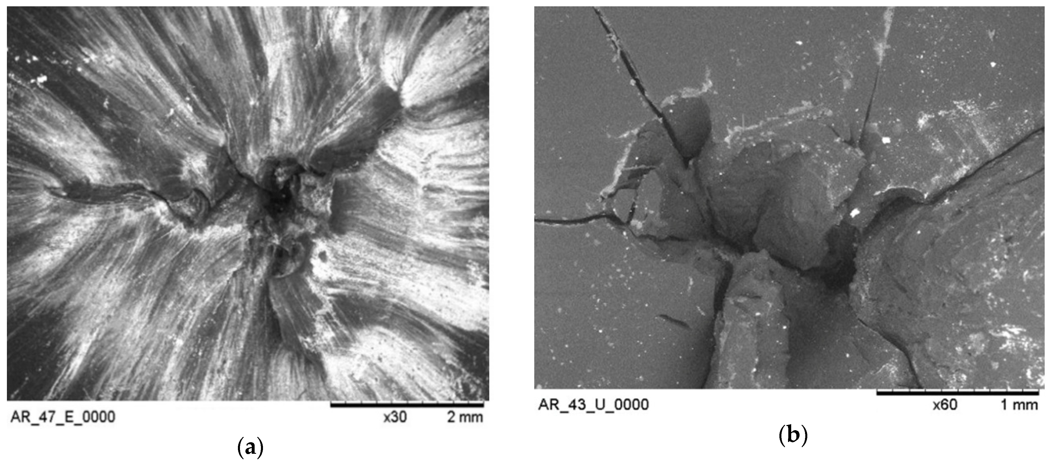
Ionomeric panels tested at different temperatures in the range −40 °C/70 °C with firearm shots (.45ACP bullets) showed full healing after single impacts. Multiple-shot tests were carried out to investigate the ability to heal in the case of consecutive shots in the same location. The results obtained by these tests showed that at up to two perforations at the same point, leaving about 30 s between each other, the material healed properly. All the samples passed the leakage tests. On the other hand, SEM observations, see
Figure 9, showed a somewhat worse re-welding with respect to a single healing.
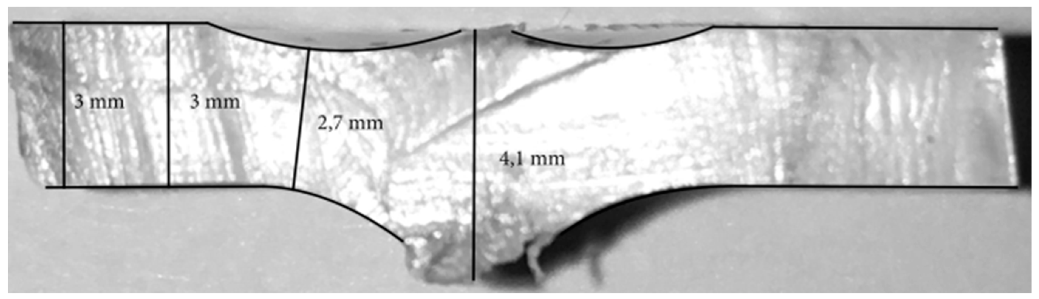
It was observed that, after the first shot, plastic deformation occurs that changes the thickness of the sample in the impacted area, as can be seen in
Figure 10. In particular, material stretching in the outer part of impacted area leads to a somewhat reduction in the thickness.
As long as the panel thickness/projectile diameter ratio is greater than the critical one ((
t/
d)
crit ~ 0.2 [
20]) the healing still takes place, but the local mechanical characteristics are lowered by the phase changes and the permanent plastic deformation of the previous shot.
A third shot was carried out at the same point of perforation and, as expected, the material did not heal completely. More specifically, an elastic return was observed, but the edges of the molten area did not weld properly, creating a small hole through which a slight leakage of water could be observed. However, it should be pointed out that in all cases, the residual hole is far smaller than the projectile, so that healing, although partial, is still effective.
Tests were repeated at a different temperature (
Vin 282 m/s,
Ein 592 J), and the results are reported in
Table 3. It is interesting to observe that even at the lowest temperatures tested, a melting/welding effect and self-healing were evident. In a few instances, at very low temperatures, panels showed extensive damage and cracks when impacted. However, locally, in the shot area, hole healing was always observed.
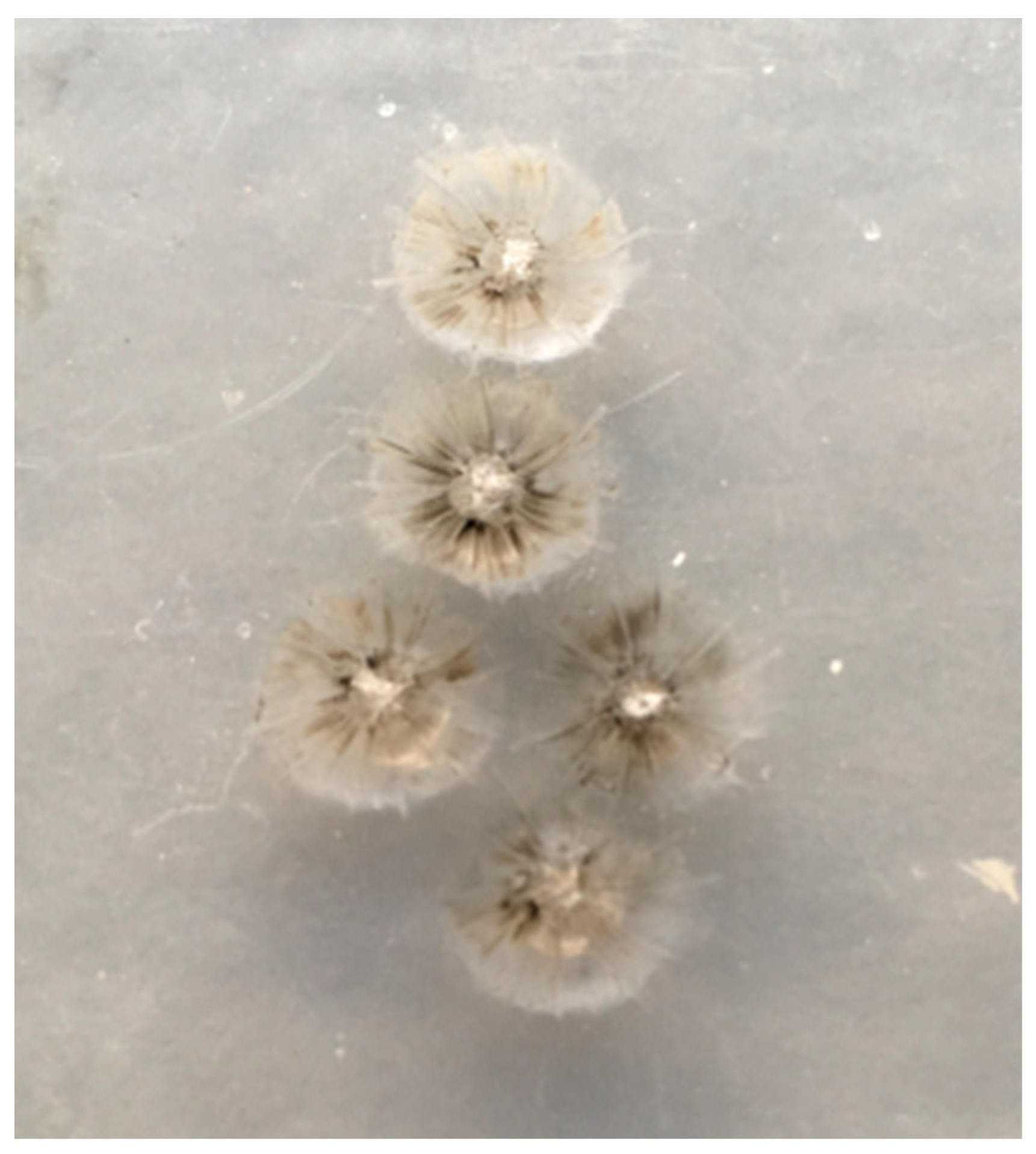
Additional multi-shot tests were conducted at different points within a range of 20 mm. Complete healing was observed in all tests, see
Figure 11.
3.2. Tests with Integrated Fluid Container
Previous tests conducted on self-healing panels with a range of thickness and spherical projectiles with different sizes indicated the panel thickness/sphere diameter (
t/
d) ratio as a characteristic parameter. It was observed that a
t/
d ratio of about 0.2 results, which distinguishes full healing from partial healing conditions [
19].
Confident with the results obtained by the ballistic tests on the ionomer, authors have integrated the self-healing polymer in a simplified model of a fuel tank filled with water, see
Figure 2 and
Figure 3, investigating
t/
d ratios comparable to previous tests. The addition of water inside the tank seems to have a quite limited effect over the self-healing capacity of the ionomeric wall; a slightly easier healing occurs with any panel thickness, possibly due to the lower panel deflection and material deformation in the surroundings of the impact.
A somewhat lower healing efficiency was observed when both water and Explosafe® filler (single block or pellets) were inserted into the tank.
Figure 12 compares the results of ballistic tests with and without water and Explosafe
® in the tank; “air leakage” specifies conditions when only partial healing was indicated by leakage tests. A higher
t/
d threshold than in previous configurations was noted, indicating a lower healing efficiency. A possible explanation of this can be linked to a temporary pressure increase during impact due to a reflection wave, interfering with the healing process.
Leakage tests and SEM analysis gave additional information regarding the healing efficiency. Most of the tested panels did not show any evidence of water spilling after bullet perforation; however, air leakage tests resulted more critical and about half of the panels showed air passage. This confirms that self-mending is a general tendency in this material, although in some cases, it is not able to provide full hole sealing. A comparison of SEM images of the impact area observed after tests indicates that the presence of water leads to lower petalling, possible indication of minor local deformation in the hole area, compared to the configuration in air, see
Figure 13.
Tests with an imposed overpressure inside the tank showed that in all cases, the hole generated by the projectile passage was fully closed or at least extensively reduced, see
Table 4. When a small residual hole remained, spilling of water was observed, although at a very limited rate. Again, as in previous cases with a water-filled tank, inhibited petalling was noticed and the presence of anti-sloshing filler, either as a single block or as pellets, seems to be somewhat detrimental for the self-healing efficiency.
In all tests with a water-filled tank, pressure variations were recorded during the entire impact event by sensors placed near the impacted wall (P1) and near the opposite wall (P2); sensors placed in other locations did not provide clear results. As a general trend, it was observed that the bigger the impacting sphere, the higher the pressure peaks. This is expected both considering the larger volume of the projectile entering the tank and the higher deflection of the panel due to the impact energy.
Figure 14 shows, for example, the pressure peaks recorded near the impacted wall of the non-pressurized tank in tests with spheres of different size. A comparison between different configurations shows that a remarkable reduction of pressure peaks is observed when Explosafe® anti-sloshing filler is present, see
Figure 15, with pellets leading to a more efficient pressure peak reduction. In the case of a pressurized tank, a similar trend was observed, again with a more efficient peak reduction effect given by filler in pellets form. It was noticed that during impacts, the internal overpressure was maintained and, only when a small hole remained unsealed after impact, a slow reduction of pressure was recorded afterword.
4. Conclusions
In this work, the self-healing behavior of an ionomeric system was explored in view of safety-related aeronautical applications. Ballistic tests were conducted in a variety of aging and environmental conditions; the mechanical characterization of healed materials evidenced the capacity of the ionomeric system to react to damages and provided information regarding the damage and healing mechanisms. Shooting tests showed that self-mending behavior and hole closure can also be observed after multiple shots and at different temperatures. These results support the interest in the development of ionomeric systems and their employment for the design of new applicative solutions where an efficient autonomic repairability is required. In the case of punctures by high-speed objects, the safety level of fuel tanks may be improved by the integration of self-healing walls and explosion suppression systems based on aluminum cellular fillers. The response of such configurations to bullet impacts has been experimentally explored and showed encouraging results even though a reduction of the healing efficiency at the lowest temperature suggests that improvements in the behavior in these conditions require further research.
The presence of the inner liquid improves the mending efficiency, supporting the deformation recovery during the healing process; although, its pressurization can affect the healing efficacy. However, even when full healing was not attained, a remarkable and consistent reduction of the punctured area and fluid spilling was recorded. The presence of an anti-sloshing filler placed inside the tank at a sufficient distance from the self-healing wall effectively helps in reducing the over-pressure peaks in the case of a perforating impact.


