Article

High-Bandwidth Morphing Actuator for Aeroelastic Model Control

School of Engineering, University of Liverpool, Liverpool L69 3GH, UK
*
Author to whom correspondence should be addressed.
Aerospace 2019, 6(2), 13; https://doi.org/10.3390/aerospace6020013
Submission received: 31 December 2018 / Revised: 29 January 2019 / Accepted: 30 January 2019 / Published: 1 February 2019
(This article belongs to the Special Issue Aeroelasticity)

Abstract

:
The design and testing of a high-bandwidth continuous actuator for aeronautical applications is presented hereinafter. The actuator has a dual goal of controlling both the aeroelastic behaviour and the flight mechanics of the model in which it is installed. In order to achieve these aims, the actuation bandwidth of the active aerofoil, as well as its static camber variation, have to be sufficiently high. The camber morph is achieved by using tailored piezoelectric patches in a sandwich configuration with a linear trailing edge slider to allow the necessary compliance. The morphing actuator is designed for a NACA 0018 aerofoil with a chord of 300 mm and a span of 40 mm. Static and dynamic experimental tests are carried out on a prototype, and a camber variation control technique is implemented. It is proved that the actuator bandwidth is up to 25 Hz and the equivalent maximum deflection is ± 15 degrees. This solution is shown to be a viable light-weight alternative to the conventional brushless/servo-motor approach currently used in aeroelastic models.

1. Introduction

One of the main challenges during the development of aeroelastic models is the design of the control-surface actuation system. Certain requirements, such as the maximum flap deflection and hinge moment, are dictated by the flight mechanics (i.e., the operational dynamic pressure), while the required actuation bandwidth depends upon the dynamic behaviour of the entire structure and the control objective. To introduce active vibration/flutter suppression techniques, it is necessary that the actuation frequency be at least double the natural frequency of the phenomenon to be controlled. The conventional approach uses geared brushless motors, e.g., [1,2], but their size and weight often make it difficult to fit them inside the aeroelastic structure without compromising the original design. Over the past decade, various discrete-flap solutions, featuring piezoelectric elements, have been proposed to overcome such limitations. Ardelean et al. [3] developed a piezo-stack actuator in a V-shaped configuration that is able to produce a control-surface displacement of ± 7 degrees with a bandwidth of 15 Hz [4], but the system requires a quite significant internal volume and its weight is comparable to, if not higher than, the equivalent traditional electric actuator; moreover, the amount of flap deflection is small and it is subject to freeplay due to the numerous linkages present. Heinze et al. [5] also designed a piezo-stack solution for the actuator of their High Aspect Ratio Wing (HARW) that produces a deflection less than ± 3 degrees with a bandwidth up to 20 Hz. The tiny deflection makes this configuration unsuitable for a wide range of applications. Both solutions present acceptable bandwidth but are discrete and limited in the maximum displacement. During the early 1990s, advancements in piezoelectric materials allowed them to be shaped into patches to be embedded in the structures. Preliminary studies on the ability of such materials to alter the camber of an aerofoil were carried out by Lazarus et al. [6], whom explored the feasibility of using strain-actuated adaptive structures to deform a typical wing box section. Barrett et al. [7,8,9] designed and tested an all-movable control surface actuated through precompressed piezoceramic sheets showing that deflections up to around ± 22 degrees with a bandwidth of 11 Hz can be achieved. Pinkerton et al. [10], at the Langley Research Center, developed a piezoeletric actuator based on a THin-layer composite-UNimorph ferroelectric Driver and sensor, known as “THUNDER”, which was able to increase the leading edge camber of a small aerofoil, thereby introducing significant change in aerodynamic loads. More recently, the growing interest in the camber-morphing aerofoil, together with the development of the NASA Langley Research Centre Macro-Fiber Composite (MFC) Actuator [11,12]—thin, light and flexible unidirectional piezoceramic fibres formed in rectangular shapes—resulted in a new family of morphing actuators with continuous flaps and skin-embedded piezopatches. Cobb et al. [13] used six MFC patches to actively control the buffet-induced vibrations on the Block 15 F-16 ventral fin. Bilgen et al. [14] developed a bidirectional variable-camber aerofoil employing eight MFC 8557-P1-type actuators in a bimorph configuration to construct the active surfaces and a single four-bar (box) mechanism for skin compliance. The fabricated aerofoil had a 15 mm thickness, a 127 mm chord, and a 133 mm span. Pankonien et al. [15] further developed this design introducing Synergistic Smart Morphing Ailerons (SSMA) where the compliant box aerofoil was replaced by a flexural box aileron. Molinari et al. [16] designed and tested a NACA 0012 lightweight (<0.5 kg) wing (150 mm × 150 mm × 80 mm) with a compliant inner structure where the roll-attitude was controlled by morphing the camber via three MFC M-8557-P1 patches applied to the Carbon-Fibre-Reinforced Plastic skin of the model. The solution proposed by Debiasi et al. [17] instead features four MFC M-8557-P1 patches in a sandwich configuration with 0.125 mm thickness titanium sheet in between. The section studied is a NACA 0015 (150 mm chord and 158 mm span) with a leading edge linear slider for skin compliance. Both of these solutions were designed with primarily static objectives and aerofoils were tested at different angles of attack to study the aerodynamic performance. Their aim was not to provide an alternative to a discrete control surface but to morph the entire camber of the aerofoil. Even more recently, the same technology was used to optimise the aerodynamics by changing the wing geometry for the different flight phases [18].
However, to the best of the authors’ knowledge, none of the continuous morphing solutions presented above are designed specifically for aeroelastic control and they all present limits in terms of bandwidth, maximum equivalent deflection or size/weight. The goal of this work is to demonstrate the ability of the proposed design to satisfy the requirements highlighted earlier and, by doing so, to provide an alternative to the traditional and well-known brushless motor by allowing a simplification in the model design and a weight reduction, while retaining the necessary high bandwidth, torque and deflection properties. The proposed actuator is suitable for a wide range of low-speed models (e.g., Tang et al. [19]), since it satisfies most of the typical wind tunnel aeroelastic actuators requirements (i.e., actuation bandwidth, hinge moment and maximum deflection—if used for controlling the flight mechanics as well). The actuator is ultimately intended to be tested as part of a flexible aeroelastic wing known as MODFLEX (the MODular aeroelastic FLEXible wing) developed at the University of Liverpool. According to preliminary data obtained by Fichera et al. [20], the requirements of the High-Bandwidth Morphing Actuator (HBMA) are a bandwidth of up to 20 Hz with an equivalent static deflection of ± 15 deg and a hinge moment greater than 0.05 N/m.
The contents of this paper are arranged as follows. The design of the high-bandwidth morphing actuator is presented in Section 2, including details of the MFC configuration chosen and the 3D printed components. Experimental test results are discussed in Section 3, including static-deflection, static-load and dynamic tests in Section 3.1, Section 3.2 and Section 3.3. The implementation of a low-level Proportional Integral Derivative (PID) controller for displacement control of the morphing sector is given together with experimental results in Section 3.4.

2. High-Bandwidth Morphing Actuator (HMBA) Design

The goal of this work is to design, manufacture and test a camber-morphing trailing edge to be used as an actuator for aeroelastic models in general and specifically for the MODFLEX rig [20]. The design concept is explained in the present section.
The HBMA, shown in Figure 1, is composed of two sheets, one of which is an MFC piezo-patch sandwich and the other a 0.5 mm thickness aluminium sheet. Both sheets are fixed at one end to the undeformable main aerofoil structure by L-shaped ABS (Acrylonitrile butadiene styrene) plastic brackets, and male and female T-shaped sliders are attached at the other ends of the MFC sandwich and aluminium sheet, respectively, to provide the necessary compliance. The overall dimensions of the actuator are 128 mm length (of which 88 mm unsupported) and 40 mm width, and the total mass is 30 g. Figure 2 shows the side view of the actuator, including the engineering drawing with principal dimensions (Figure 2a) and a photograph of the tail section (Figure 2b).
Figure 3 shows the design of the linear T slider. The length of the T portion was chosen in order to allow ± 7.5 mm of linear sliding which ensures up to ± 20 deg and 20 mm of trailing edge displacement. Detailed dimensions may be obtained from the authors upon request.

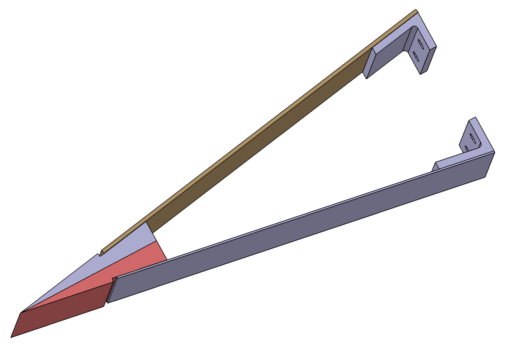
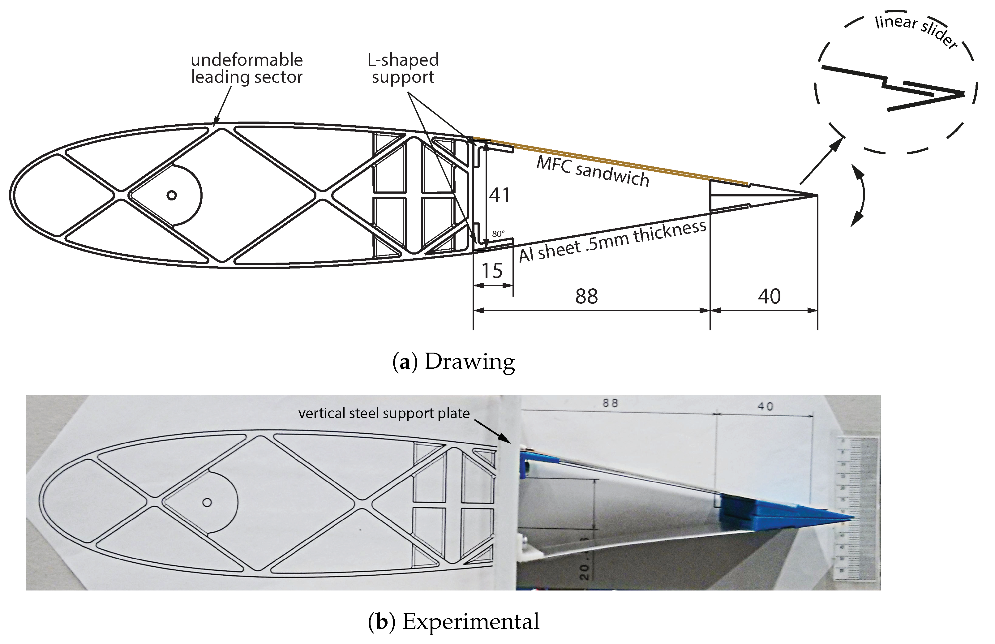
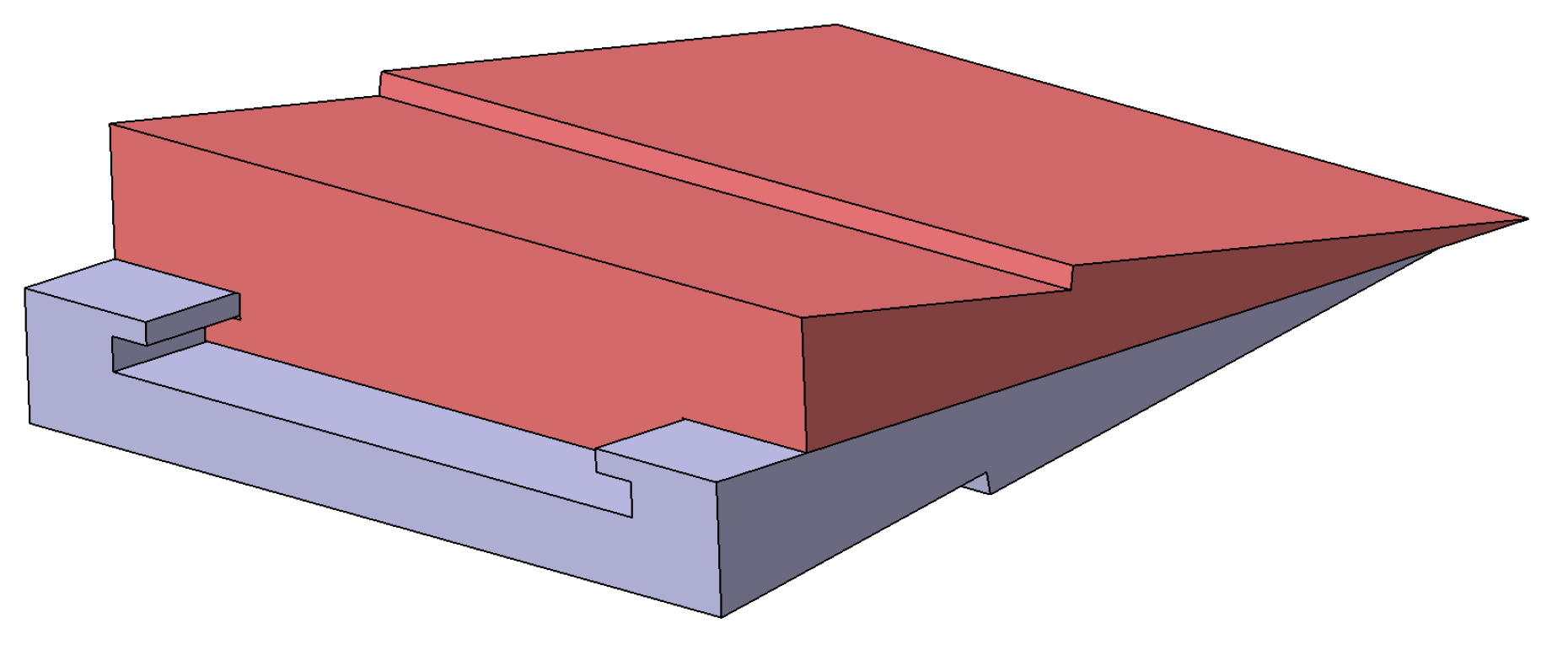
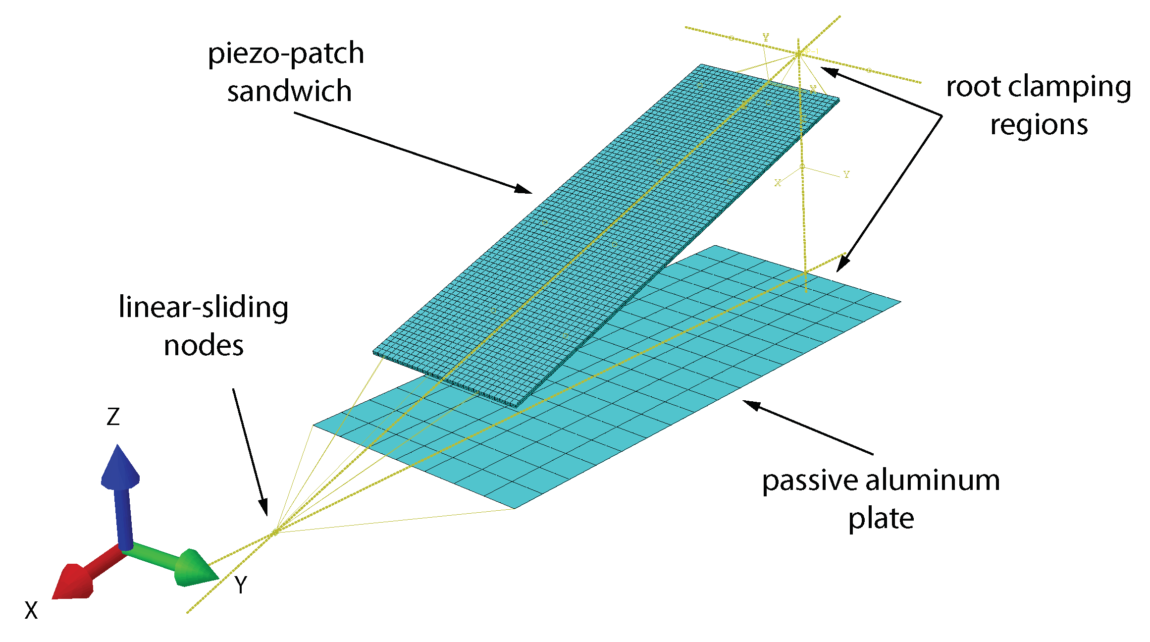
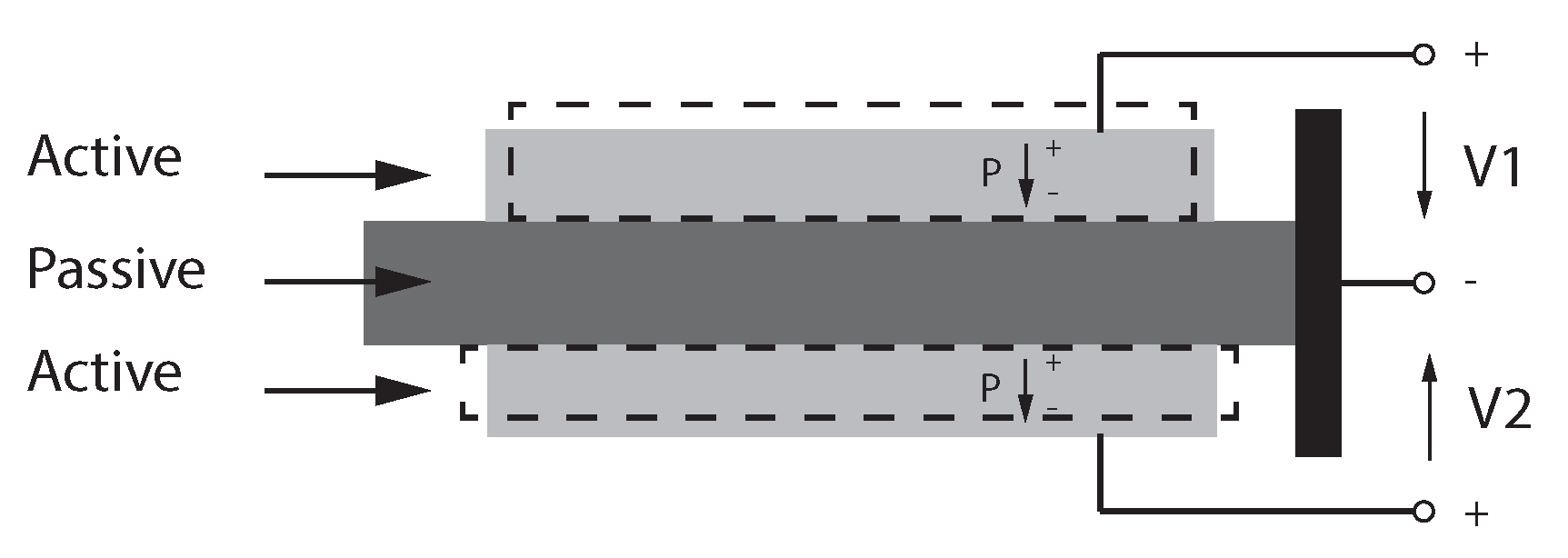
2.1. Actuator Configuration

The NASA Langley Research Centre Macro-Fibre Composites (MFC) are orthotropic actuators consisting of unidirectional piezoceramic fibres embedded in an epoxy matrix and sandwiched between two polyimide films with an interdigitated electrode pattern that is used for both poling and actuation [11]. The major actuation is along the direction of the piezoceramic fibres exploiting the d 33 parallel effect that corresponds to the deformation of the specimen in the direction of the driving electric field. The actuation of MFC actuators, prepackaged as patches, is accomplished by applying an asymmetrical voltage between 500 V and + 1500 V leading to asymmetrical actuation behaviour, the maximum contraction being one-third of the maximum elongation. Since the piezo-patches generate an in-plane effect, it is necessary to bond them to a passive material to produce a bending effect. Symmetric bending can be achieved with increased blocking force, but at the cost of reduced bending deformation, by bonding together two piezo-patches in an antagonistic configuration.
The thickness and mechanical properties of the passive material in the piezo-patch sandwich were determined by using the bi-metallic strip analogy with the objective of maximizing the bending deflection. A stainless steel shim with Young modulus of 210 GPa and 0.012 mm thickness proved to be the best solution. A 3-D Finite Element (FE) model of this arrangement was then developed in Abaqus following the approach proposed by Latalski et al. [21] with the piezo-patches modelled as an orthotropic, homogeneous piezoelectric material, and was validated using data released by the manufacturer using the analytic results obtained by the bi-metallic strip analogy. Finally, the complete actuator model was developed and used to choose the number of piezo-patches and the dimensions and material properties of the passive aluminium sheet ( 0.5 mm thick, E = 70 GPa). Figure 4 shows the FE model of the HBMA composed of two bodies with the piezo-patches of the sandwich represented by solid 20-noded, second order elements (Abaqus C3D20E). The stainless steel shim was modelled using 8-noded shell elements (Abaqus S8R) with piezo-patches bonded on each of them by tie constrains. Electric potential boundary conditions were defined at each end of the piezoeletric sheets ( 500 V/ + 1500 V and vice versa). The roots of the sandwich and the aluminium sheet were rigidly constrained and the tips were fixed by a kinematic constraint to allow sliding.
The sandwich configuration shown in Figure 5 presents two MFCs bonded, one to each side of the stainless steel shim with 3M DP460 epoxy glue. Besides increasing the structural stiffness of the skin, this solution allows symmetric deflection of the actuator when operating the two patches around a zero deflection condition and doubles the bending blocking force. The drawback of this configuration is a decrease in the maximum theoretical deflection from that produced by a single patch plus passive material due to the antagonist effect of one patch on the other. Internal ribs, within the actuator inner volume, were deemed to be unnecessary because it has been demonstrated [14,22] that the out-of-plane deformation of the skins due to the aerodynamic load was negligible for actuators with chord and span up to 100 mm and airspeed up to 40 m/s.

2.2. Actuation Design Comparison

To conclude the design process, a comparison between the HBMA and a standard actuator was carried out. The so-called standard actuator is the one chosen for the discrete flap of the MODFLEX [20] and it has to satisfy the same requirements for which the HBMA has been designed. It is composed of a brushless motor (EC16 60W, Maxon Motor®, Sachseln, Switzerland) plus its related encoder and all the parts necessary to assemble it into the wing sector. The electric motor is more difficult to embed into the structure than the piezo-patch actuator, requiring a tailored design of the structure in order to do so. This increase in complexity is accompanied by an increase in weight: the overall weight-per-length (WpL) of the HBMA is 7.5 g/cm, whereas for an equivalent chord portion, the WpL of the standard actuator is 21.8 g/cm.

3. Experimental Tests

The experimental setup is illustrated in Figure 6. Three laser displacement sensors are used to read the camber variation at three points along the chord of the morphing actuator, the displacement signals are either acquired by a dSPACE GmbH® (Paderborn, Germany) real-time system or by a Siemens PLM® (Plano, TX, USA) modal analysis setup. The voltage supplied to the piezo-patches is either supplied by the Siemens PLM® system through dSPACE® or directly generated by dSPACE®. Two Trek Inc.® (Lockport, NY, USA) PA05039 high-voltage power amplifiers raise the dSPACE® output voltage ( 2.5 V/ + 7.5 V) to the required Smart Material Corporation® (Sarasota, FL, USA) MFC level ( 500 V/ + 1500 V) by introducing a gain of 200. Since the HBMA presents a sandwich configuration, it is necessary to operate the two piezo-patches in an antagonistic manner around a non-zero voltage level, i.e., + 500 V. The maximum deflection is then achieved by supplying one MFC with + 1500 V while the other with 500 V and vice versa for the opposite maximum deflection. In what follows, the percentage convention will be used: 0% refers to the zero-actuator deflection ( + 500 V for both the MFCs), 100% refers to the maximum deflection ( + 1500 V for one MFC and 500 V for the other). Following the standard aeronautical convention, the downward deflection of the trailing edge is considered positive. It is to be noted that, in all the tests presented here, the piezo-patch sandwich constitutes to the upper skin and the aluminium plate constitutes the lower skin.

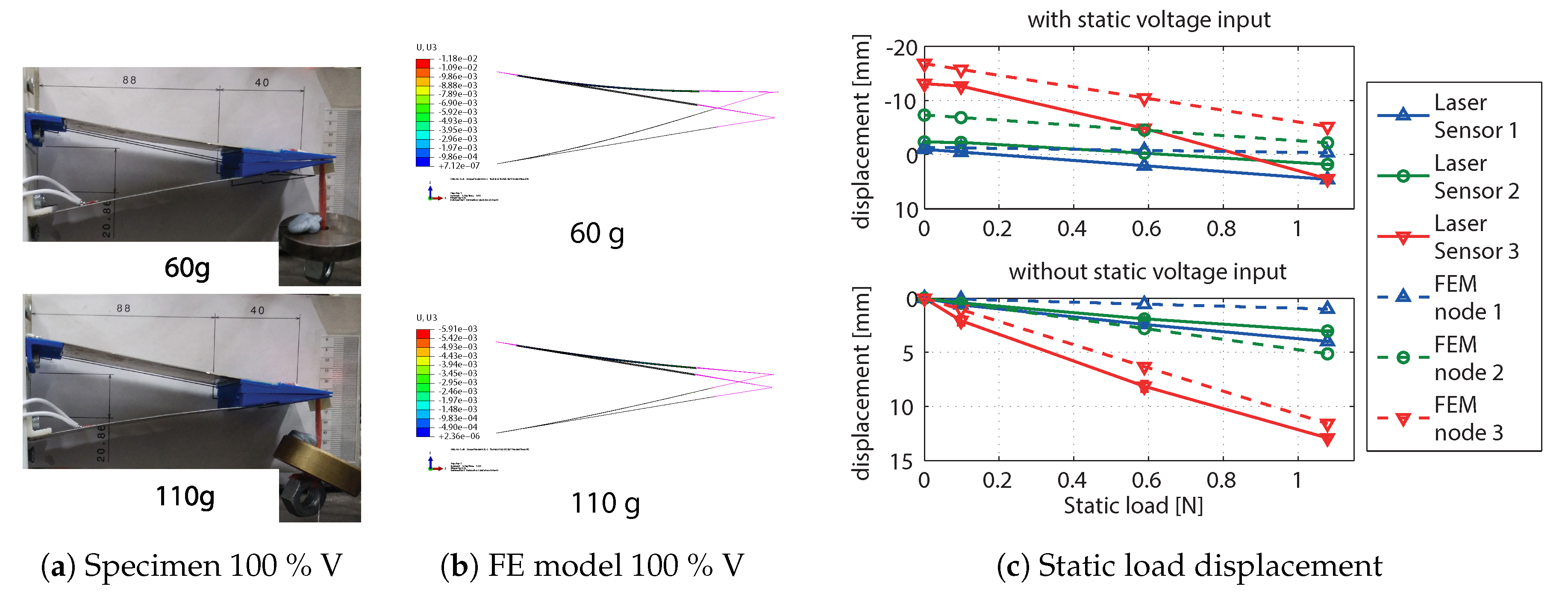
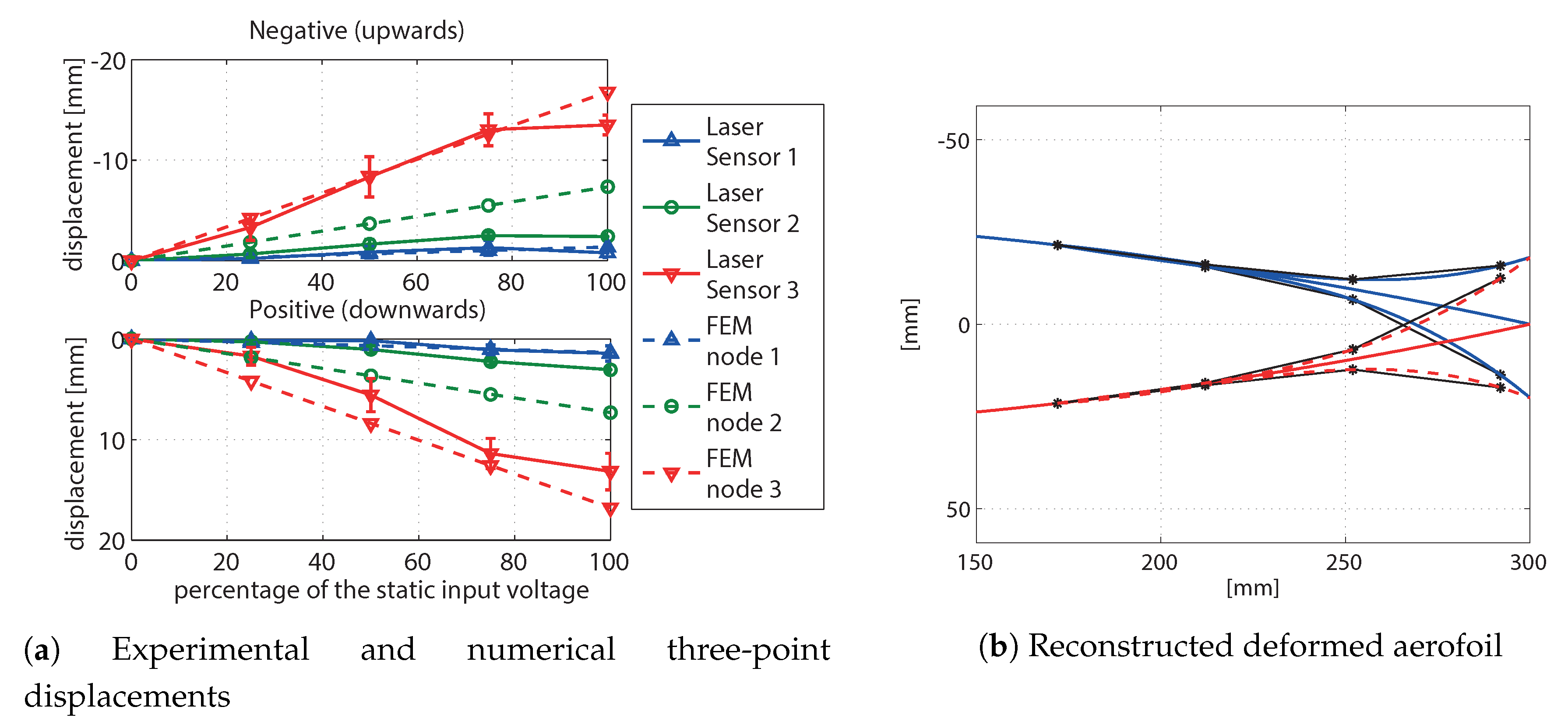
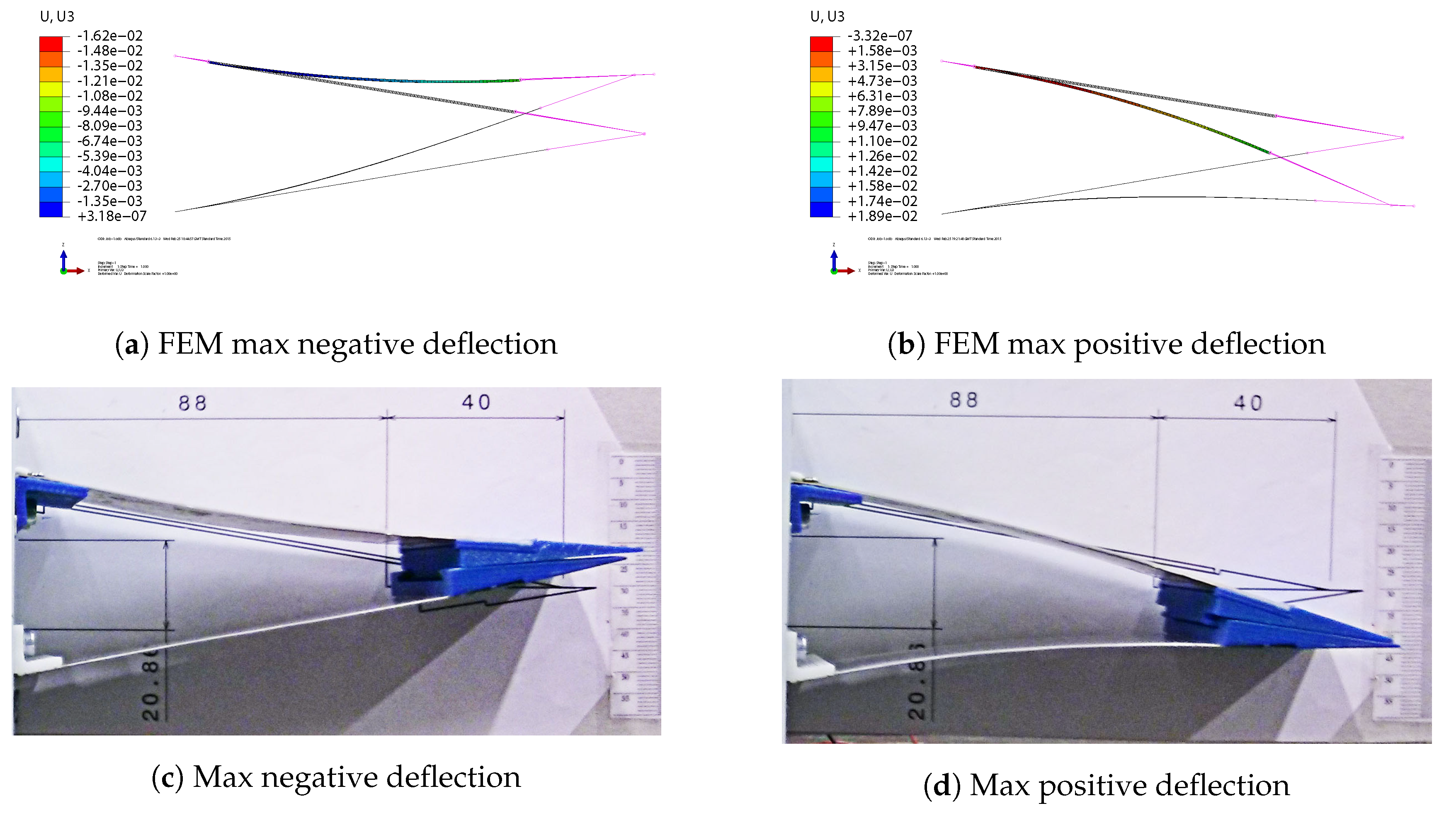
3.1. Static Deflection Test

A static deflection test was carried out on the morphing rig previously described. The actuator was supplied with a control input from 0% to 100% with increments of 25%, following the percentage convention presented earlier. This resulted in positive and negative displacements of the trailing edge, depending upon the combined polarity of the voltage. The displacements recorded by the three sensors are plotted in Figure 7a together with the error bars of their standard deviation; the results obtained by the FE model are given by the dashed lines. The deformation proved to be almost linear in both directions, reaching a maximum trailing edge displacements of 15 mm and + 13 mm, respectively. The normalised RMS error (between the FE and the experimental results) is 0.2 for the first and third laser sensor readings but increases to around 2 for the second reading. The discrepancy seems to be due to differences in the camber shape along the MFC sandwich. In the experimental model, the deflection is concentrated in the portion of the actuator close to the trailing edge, while in the FE model it is more evenly distributed along the whole length of the piezo-patches. This different behaviour can be explained as a consequence of the presence of the two gluing areas, with the L-shaped support and the linear slider, that alter the ability of the piezo-patch sandwich to deform as per design. The lower diagram of Figure 7a shows that the positive deflection is slightly smaller than the negative one, possibly due to the design choice that features the active element only on the upper skin. The reconstructed maximum positive and negative deformations are shown in Figure 7b. The continuous lines are the third order polynomial interpolation of the measured displacements while the dashed ones represent the lower skin FE displacement prediction. Figure 8 depicts the two maximal deflections of the actuator in the positive and negative directions, both numerically and experimentally.

3.2. Static Load Test
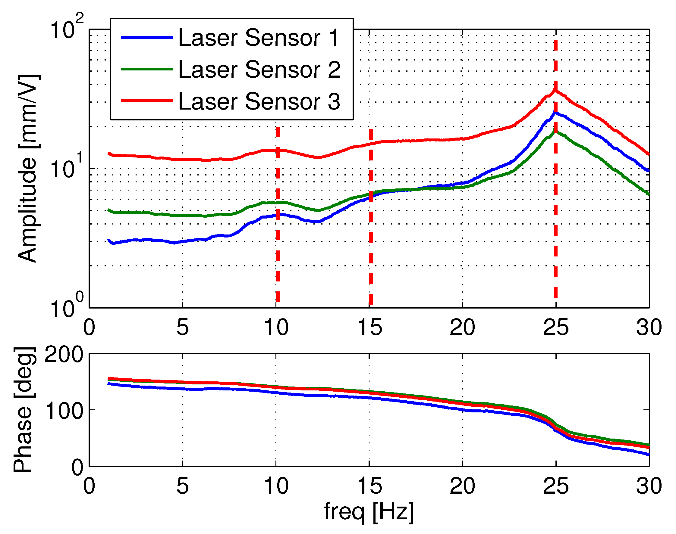
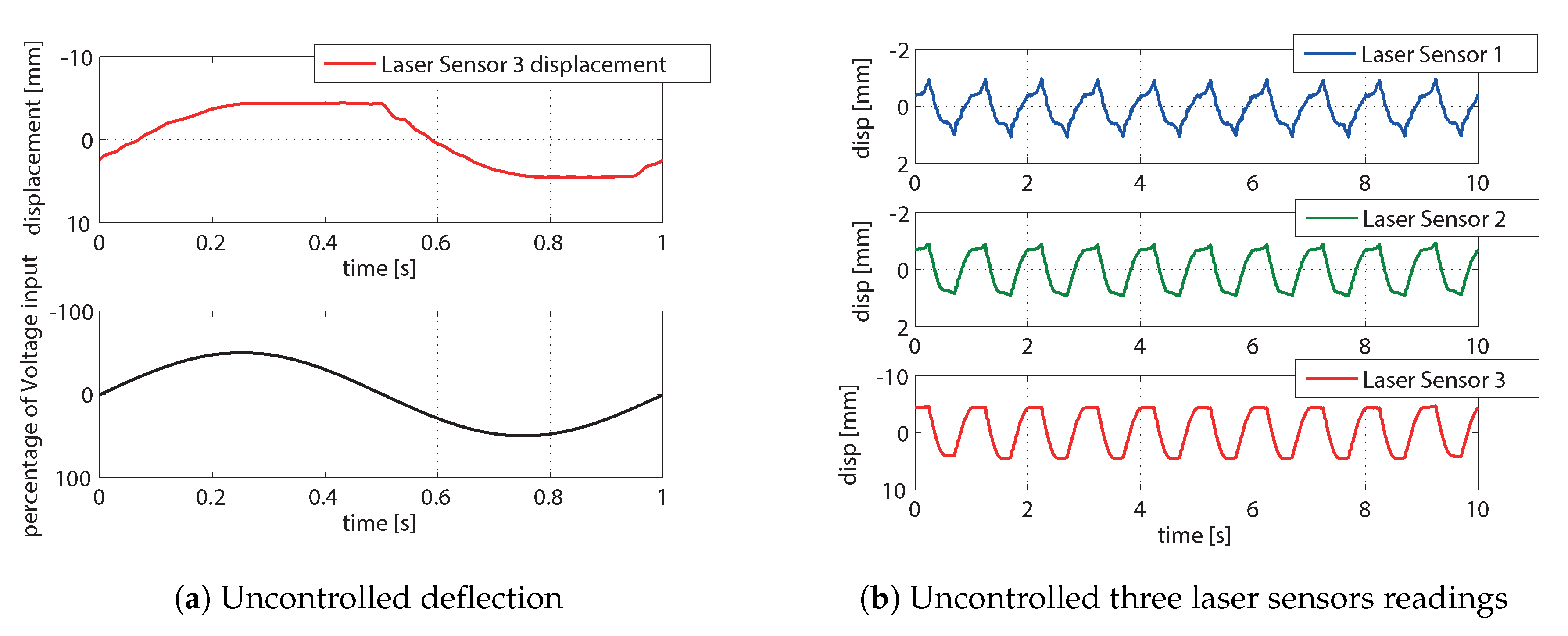
Static load tests were conducted at the maximum negative deflection and a mass hung from the trailing edge, as shown in Figure 9a. The load was increased from 0 g to 110 g with intermediate values of 10 g and 60 g. Experimental results are shown as continuous lines in Figure 9c, whereas the dashed lines represent FE predictions. The lower diagram of Figure 9c shows the deflections under the same load, but without any voltage applied. The numerical model is seen to be stiffer than the experimental one, which might be due to softer L-shaped brackets and other manufacturing imperfections in the constraints of the experimental model. The morphing actuator was found to be capable of delivering a force at the trailing edge of approximately 1 N. Considering the length of the actuator, its “equivalent” stall torque was determined to be greater than 0.1 Nm, enough to fulfil the hinge moment requirements of similar-size aeroelastic models.

3.3. Dynamic Test

A dynamic test campaign was carried out with the purpose of verifying that the bandwidth of the HBMA was greater than 20 Hz and to provide an insight into the dynamic behaviour of the system. For this test, the numerical comparison is not provided since the FE model is not capable of predicting the dynamic behaviour, being unrepresentative of the mass and friction of the experimental actuator. A stepped-sine modal test was carried out using a Siemens PLM® system with a frequency range from 1 to 30 Hz, a resolution of 0.05 Hz and delay of 7 cycles. The results are shown in Figure 10 and Table 1, which summarises frequencies and damping ratios computed by the PolyMAX algorithm [23].
Two low-frequency poles appear to be present and were traced to resonances in the wooden support structure through which the HBMA was attached to the test table—this conclusion is supported by the apparent high damping levels associated with these modes and to the absence of associated phase-shift. The single significant resonance, showing a clear phase shift, occurring at 25 Hz, is the first bending mode of the actuator. The observed dynamic behaviour of the HBMA is deemed adequate for the intended goals and its transfer function, in the bandwidth of interest, is flat enough to allow the use of the actuator in aeroelastic models, once paired with a controller.

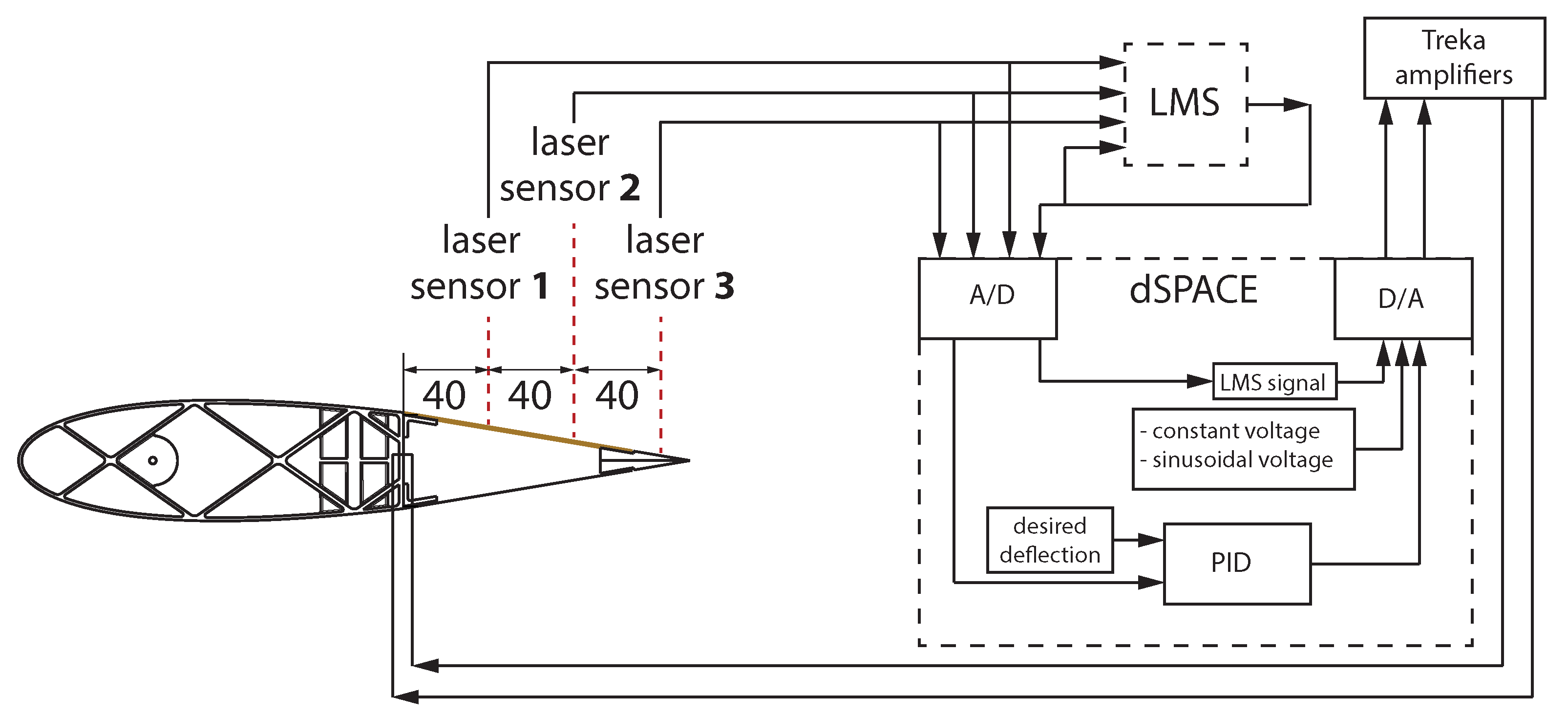
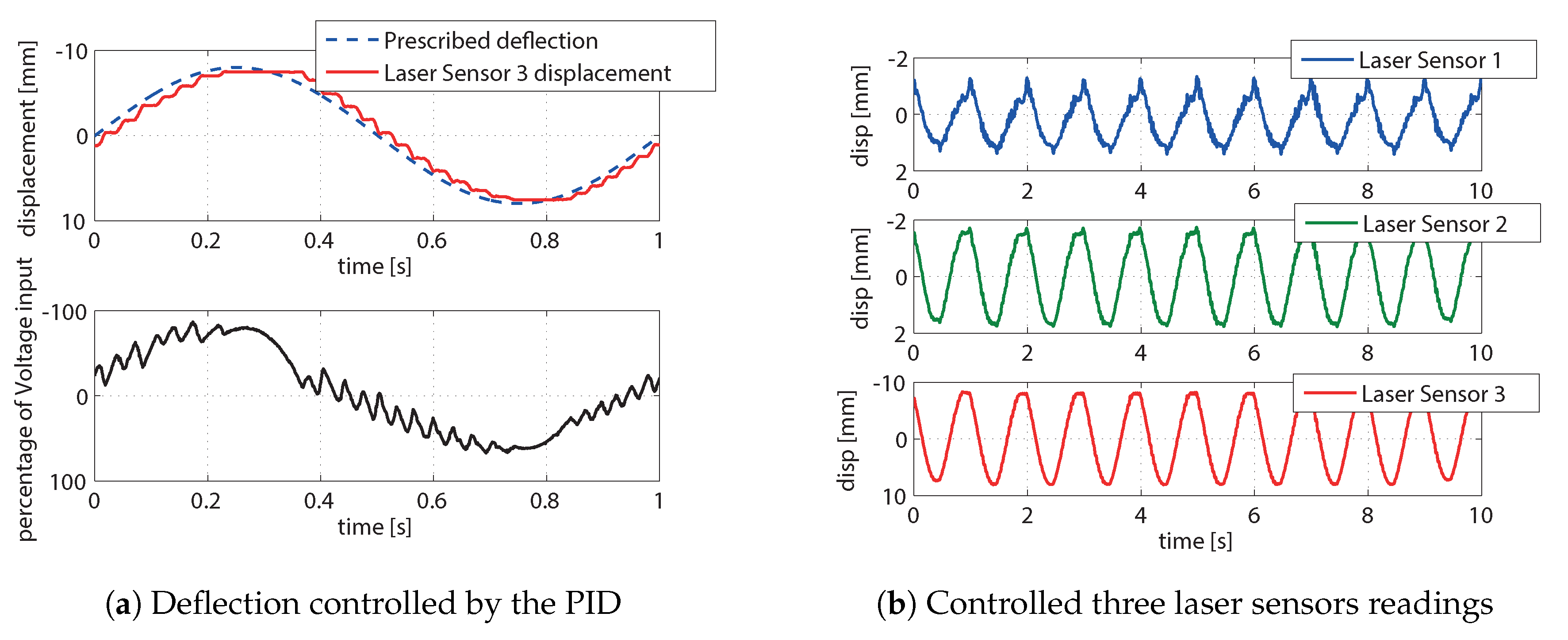
3.4. Ability of the Actuator to Follow a Prescribed Motion

The ability of the HBMA to follow a prescribed motion is investigated as well. The actuator is supplied with a sinusoidal input voltage of 50%. The displacements at three locations along the chord of the actuator for a generic 10 s interval are presented in Figure 11.
The upper plot in Figure 11a shows that the uncontrolled actuator reaches an upper and then lower plateau after a ramp transition, which is likely to be a consequence of the hysteric behaviour typical of the piezoelectric materials. To mitigate this effect, a closed-loop PID controller was implemented. Such a controller might form the inner control loop in an aeroservoelastic system, with an outer loop used to implement the different control laws for flutter/vibration suppression. Preliminary tuning of the PID controller was achieved by applying the empirical Ziegler–Nichols method [24].
Figure 6 shows the simplified block-diagram scheme for the specimen with the PID controller connected: the reading from the third laser displacement sensor is used as position feedback to evaluate the error according to a desired deflection through a real-time system. Figure 12 shows the closed-loop actuator displacement response. The upper part of Figure 12a shows the prescribed 8 mm displacement of the third laser sensor as a dashed line and the physical displacement as the full red line. The percentage voltage supplied is shown in the lower figure. The rippling of the control signal is due to amplification of the high frequency content of the feedback signal by the derivative term of the PID, which might be alleviated by improved tuning of the time constant of the first-order derivative filter as well as introducing a low-pass filter applied to the laser sensor feedback signal. It is readily seen, by comparing Figure 11a and Figure 12a, that the actuator is effective in tracking the desired output. The diagrams of Figure 11b and Figure 12b show the controlled and uncontrolled displacements measured by the three sensors for a generic 10 s time history window. The anti-plateau effect of the controller is visible also in the displacement signals recorded by the first two laser sensors that indeed show a more sinusoidal behaviour compared to the corresponding open-loop responses. The above presented PID controller has been validated in the frequency range 1–20 Hz.

4. Conclusions

The piezo-patch sandwich paired with a linear trailing edge slider and thin passive aluminium sheet has been demonstrated to be a feasible alternative to conventional flap-actuator systems for wind tunnel aeroelastic models. Both static and dynamic tests have been carried out on the HBMA, as well as the design and test of a preliminary PID inner control loop. The designed actuator fulfils the typical aeroelastic models’ requirements in terms of deflection, bandwidth and torque provided. The actuator proved to be able to morph the camber, producing a maximum static deflection of its tip equal to 15 mm, and to develop an equivalent torque of 0.1 Nm. Moreover, dynamic tests on the specimen showed a bandwidth greater than 20 Hz, suitable for controlling the first elastic modes of most low-speed aeroelastic models. From a design viewpoint, the HBMA is lighter than a dynamically equivalent brushless motor configuration and may be embedded into the structure straightforwardly without affecting the original design. The concept presented in this paper may be scaled in order to achieve a greater span of control surface, either by using the wider version of the MFC (e.g., 8557-P1) or by arranging rows of the present MFCs. Further improvements in actuator performance might be achieved by using active sandwich components for both the upper and the lower skins and modifying the mass of the slider. The T-shaped linear slider was found to be a good trade-off between maximum achievable deflection and mechanism robustness, however, alternative slider designs can be explored to best fit different systems’ requirements and to reduce the trailing edge step effect. The laser displacement sensor proved to be adequate in providing the PID feedback signal for the control test rig. However, for most experimental aeroelastic studies, independent measurement of the aerofoil section would also be required. For this reason, a co-located sensing system is now under development. A strain gauge, bonded to the passive aluminium sheet, will be calibrated to measure the actuator tip deflection.

Author Contributions

Conceptualization, S.F. and J.E.M.; investigation, S.F. and I.I.

Funding

This research was funded by Engineering and Physical Sciences Research Council (EPSRC), grant number EP/J004987/1, under the project entitled “Nonlinear Active Vibration Suppression in Aeroelasticity”.

Conflicts of Interest

The authors declare no conflict of interest.

Abbreviations

The following abbreviations are used in this manuscript:
FEFinite Element
HBMAHigh Bandwidth Morphing Actuator
MFCMacro-Fibre Composites
MODFLEXMODular aeroelastic FLEXible wing
NACANational Advisory Committee for Aeronautics
PIDProportional Integral Derivative

References

  1. Ricci, S.; Scotti, A.; De Gaspari, A.; Riccobene, L. Active Aeroelastic Control over a Multisurface Wing: Modelling and Wind-Tunnel Testing. AIAA J. 2009, 47, 1995–2010. [Google Scholar] [CrossRef]
  2. Arena, M.; Amoroso, F.; Pecora, R.; Amendola, G.; Dimino, I.; Concilio, A. Numerical and experimental validation of a full scale servo-actuated morphing aileron model. Smart Mater. Struct. 2018, 27, 105034. [Google Scholar] [CrossRef]
  3. Ardelean, E.V. High Performance “V-stack” Piezoelectric Actuator. J. Intell. Mater. Syst. Struct. 2004, 15, 879–889. [Google Scholar] [CrossRef]
  4. Papatheou, E.; Wei, X.; Jiffri, S.; Prandina, M.; Tehrani, M.G.; Bode, S.; Singh, K.V.; Mottershead, J.E.; Cooper, J. Flutter control using vibration test data: Theory, rig design and preliminary results. In Proceedings of the International Seminar on Modal Analysis (ISMA2012), Leuven, Belgium, 17–19 September 2012. [Google Scholar]
  5. Heinze, S.; Karpel, M. Analysis and Wind Tunnel Testing of a Piezoelectric Tab for Aeroelastic Control Applications. J. Aircr. 2006, 43, 1799–1804. [Google Scholar] [CrossRef]
  6. Lazarus, K.B.; Crawley, E.F.; Bohlmann, J.D.; Worth, F. Static aeroelastic control using strain actuated adaptive structures. J. Intell. Mater. Syst. Struct. 1991, 2, 386–440. [Google Scholar] [CrossRef]
  7. Barrett, R.M. All-moving active aerodynamic surface research. Act. Mater. Smart Struct. 1995, 2427, 2–15. [Google Scholar] [CrossRef]
  8. Barrett, R.M.; Gross, R.S.; Brozoski, T.F. Design and Testing of a Subsonic All-Moving Adaptive Flight Control Surface. AIAA J. 1997, 35, 1217–1219. [Google Scholar] [CrossRef]
  9. Barrett, R.M.; Gross, R.S.; Brozoski, T.F. Missile flight control using active flexspar actuators. Smart Mater. Struct. 1999, 5, 121–128. [Google Scholar] [CrossRef]
  10. Pinkerton, J.L.; Moses, R.W. A Feasibility Study to Control Airfoil Shape Using THUNDER; Technical Report 4767; NASA: Washington, DC, USA, 1997. [Google Scholar]
  11. Wilkie, W.K.; Bryant, R.G.; High, J.W.; Fox, R.L.; Hellbaum, R.F.; Jalink, A.; Little, B.D.; Mirick, P.H. Low-cost piezocomposite actuator for structural control applications. Proc. SPIE 2000, 3991, 323–334. [Google Scholar] [CrossRef]
  12. Wilkie, W.K.; Bryant, R.G.; Fox, R.L.; Hellbaum, R.F.; High, J.W.; Jalink, A., Jr.; Little, B.D.; Mirick, P.H. Method of fabricating a piezoelectric composite apparatus. U.S. Patent 6,629,341 B2, 7 October 2003. [Google Scholar]
  13. Browning, J.; Cobb, R.; Canfield, R.; Miller, S. F-16 Ventral Fin Buffet Alleviation Using Piezoelectric Actuators. In 50th AIAA/ASME/ASCE/AHS/ASC Structures, Structural Dynamics, and Materials Conference; American Institute of Aeronautics and Astronautics: Reston, VA, USA, 2009. [Google Scholar] [CrossRef]
  14. Bilgen, O.; Kochersberger, K.B.; Inman, D.J.; Ohanian, O.J. Novel, Bidirectional, Variable-Camber Airfoil via Macro-Fiber Composite Actuators. J. Aircr. 2010, 47, 303–314. [Google Scholar] [CrossRef]
  15. Pankonien, A.; Faria, C.T.; Inman, D. Synergistic Smart Morphing Aileron. In 54th AIAA/ASME/ ASCE/AHS/ASC Structures, Structural Dynamics, and Materials Conference; American Institute of Aeronautics and Astronautics: Reston, VA, USA, 2013. [Google Scholar] [CrossRef]
  16. Molinari, G.; Quack, M.; Arrieta, A.F.; Morari, M.; Ermanni, P. Design, realization and structural testing of a compliant adaptable wing. Smart Mater. Struct. 2015, 24, 105027. [Google Scholar] [CrossRef]
  17. Debiasi, M.T.; Chan, W.L.; Jadhav, S. Measurements of a Symmetric Wing Morphed by Macro Fiber Composite Actuators. In Proceedings of the 54th AIAA Aerospace Sciences Meeting, San Diego, CA, USA, 4–8 January 2016; p. 1565. [Google Scholar]
  18. Li, D.; Zhao, S.; Da Ronch, A.; Xiang, J.; Drofelnik, J.; Li, Y.; Zhang, L.; Wu, Y.; Kintscher, M.; Monner, H.P.; et al. A review of modelling and analysis of morphing wings. Prog. Aerosp. Sci. 2018, 100, 46–62. [Google Scholar] [CrossRef]
  19. Tang, D.; Dowell, E.H. Experimental and Theoretical Study on Aeroelastic Response of High-Aspect-Ratio Wings. AIAA J. 2001, 39, 1430–1441. [Google Scholar] [CrossRef]
  20. Fichera, S.; Jiffri, S.; Mottershead, J.E. Design and wind tunnel test of a MODular aeroelastic FLEXible wing (MODFLEX). In Proceedings of the International Conference on Noise and Vibration Engineering ISMA 2016, Leuven, Belgium, 19–21 September 2016. [Google Scholar]
  21. Latalski, J. Modelling of macro fiber composite piezoelectric active elements in ABAQUS system. Eksploat. Niezawodn. Maint. Reliab. 2011, 1, 72–78. [Google Scholar]
  22. Debiasi, M.T.; Bouremel, Y.; Lu, Z.; Ravichandran, V.; Khoo, H.H.; Luo, S. Deformation of the Upper and Lower Surfaces of an Airfoil by Macro Fiber Composite Actuators. In 31st AIAA Applied Aerodynamics Conference; American Institute of Aeronautics and Astronautics: Reston, VA, USA, 2013. [Google Scholar] [CrossRef]
  23. Peeters, B.; Auweraer, H.V.D.; Guillaume, P.; Leuridan, J. The PolyMAX frequency-domain method: A new standard for modal parameter estimation? Shock Vib. 2004, 11, 395–409. [Google Scholar] [CrossRef]
  24. Aström, K.J.; Hägglund, T. PID Controllers: Theory, Design, and Tuning, 2nd ed.; Instrument Society of America: Research Triangle Park, NC, USA, 1995. [Google Scholar]
Figure 1. High-Bandwidth Morphing Actuator (HMBA).
Aerospace 06 00013 g001
Figure 2. Side view of the actuator (dimensions in mm).
Aerospace 06 00013 g002
Figure 3. Trailing edge slider.
Aerospace 06 00013 g003
Figure 4. HBMA Abaqus FE model.
Aerospace 06 00013 g004
Figure 5. Bimorph configurations.
Aerospace 06 00013 g005
Figure 6. Experimental setup block scheme (dimensions in mm).
Aerospace 06 00013 g006
Figure 7. HBMA static displacement test.
Aerospace 06 00013 g007
Figure 8. HBMA static deflection.
Aerospace 06 00013 g008
Figure 9. Actuator static load test.
Aerospace 06 00013 g009
Figure 10. Frequency Response Function of the HBMA.
Aerospace 06 00013 g010
Figure 11. Uncontrolled: 1 Hz sinusoidal input.
Aerospace 06 00013 g011
Figure 12. Controlled: 1 Hz sinusoidal input.
Aerospace 06 00013 g012
Table 1. Frequencies and damping.
Mode ShapeFreq (Hz) ζ (%)
Actuator support 1 st mode10.9718.9
Actuator support 2 nd mode15.38.8
HBMA first bending mode24.954.4

