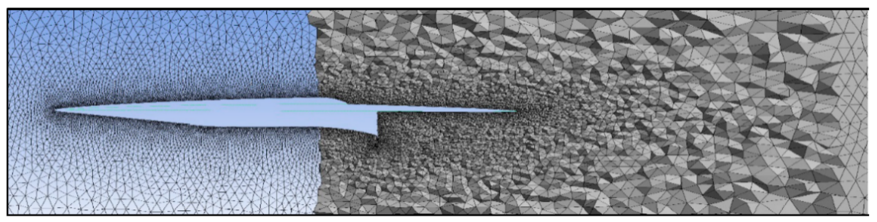
Figure 1.
3-D mesh for the integrated aircraft and engine.
Figure 1.
3-D mesh for the integrated aircraft and engine.
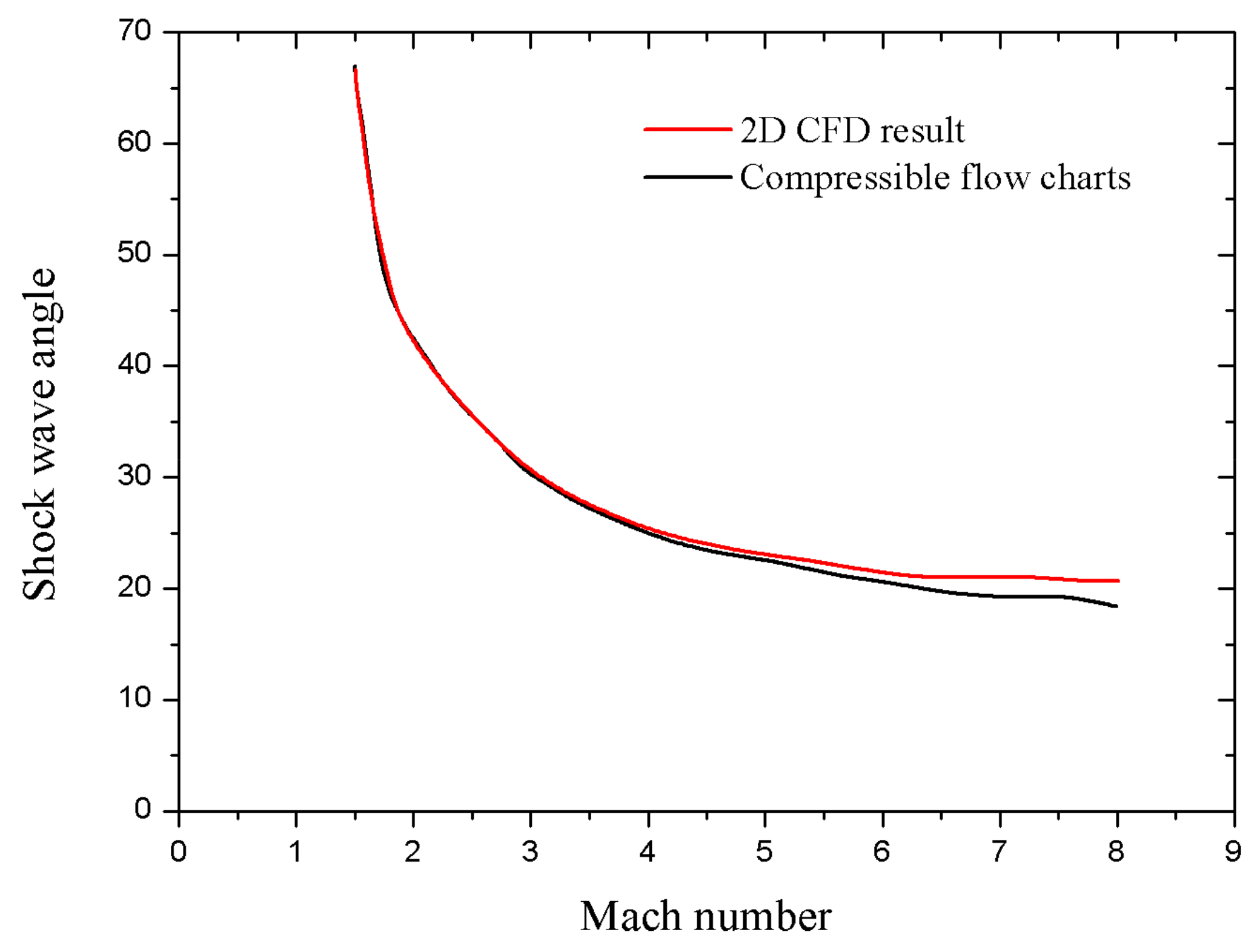
Figure 2.
Comparison of CFD results with shockwave theory.
Figure 2.
Comparison of CFD results with shockwave theory.
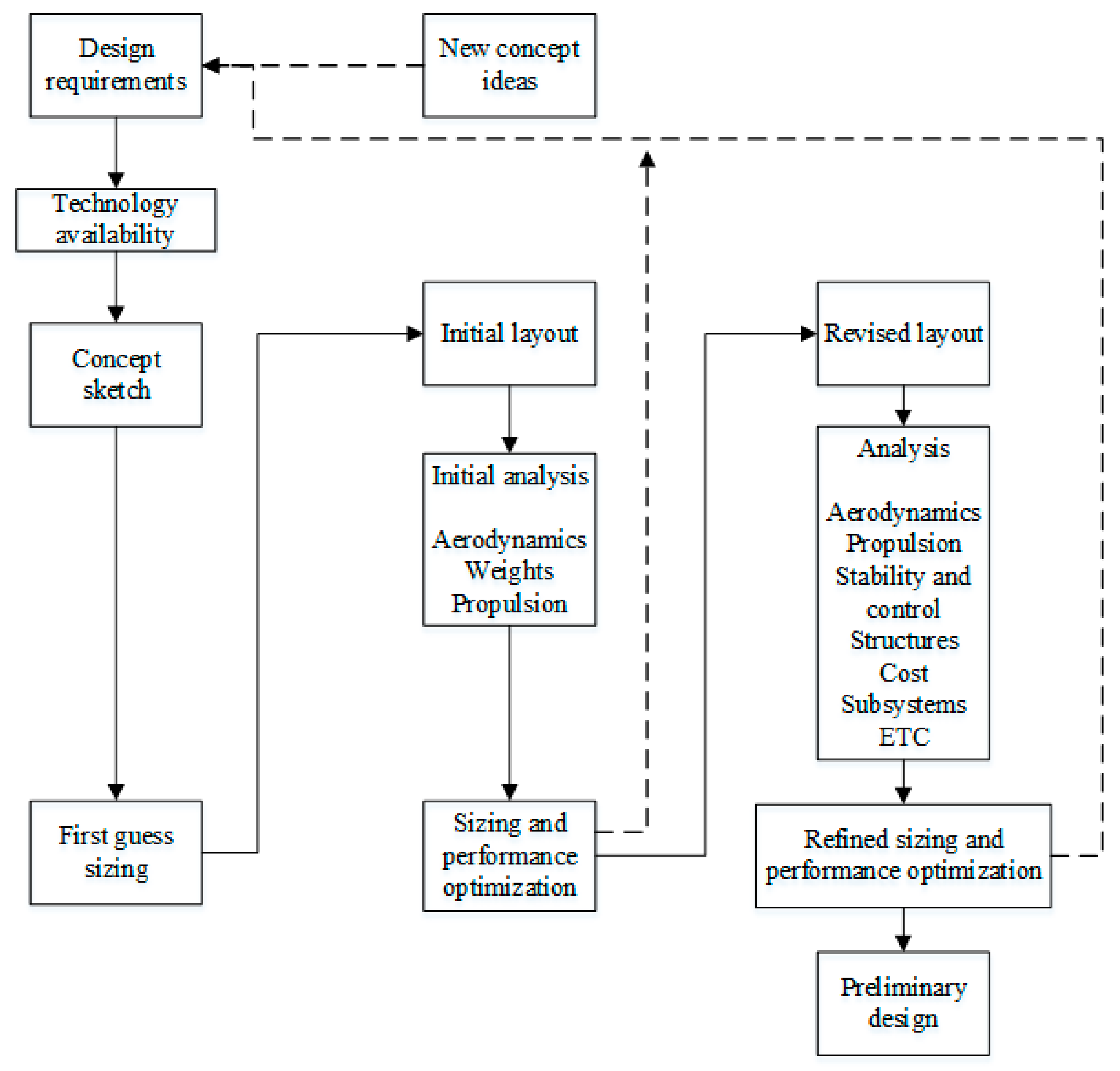
Figure 3.
Aircraft conceptual design process.
Figure 3.
Aircraft conceptual design process.
Figure 4.
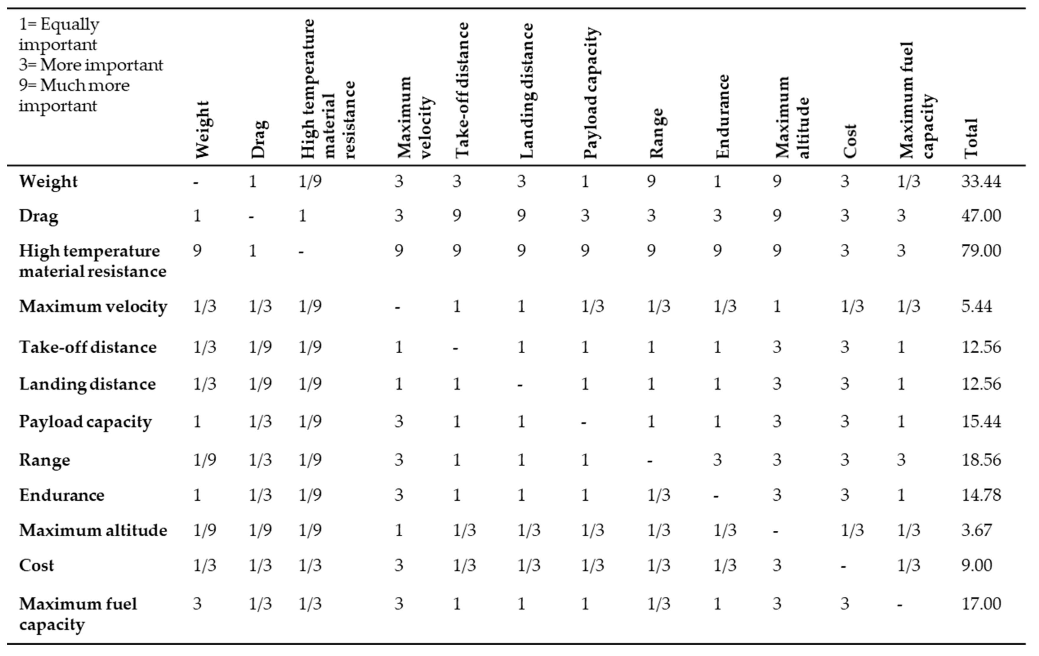
Interrelationship analysis for QFD.
Figure 4.
Interrelationship analysis for QFD.
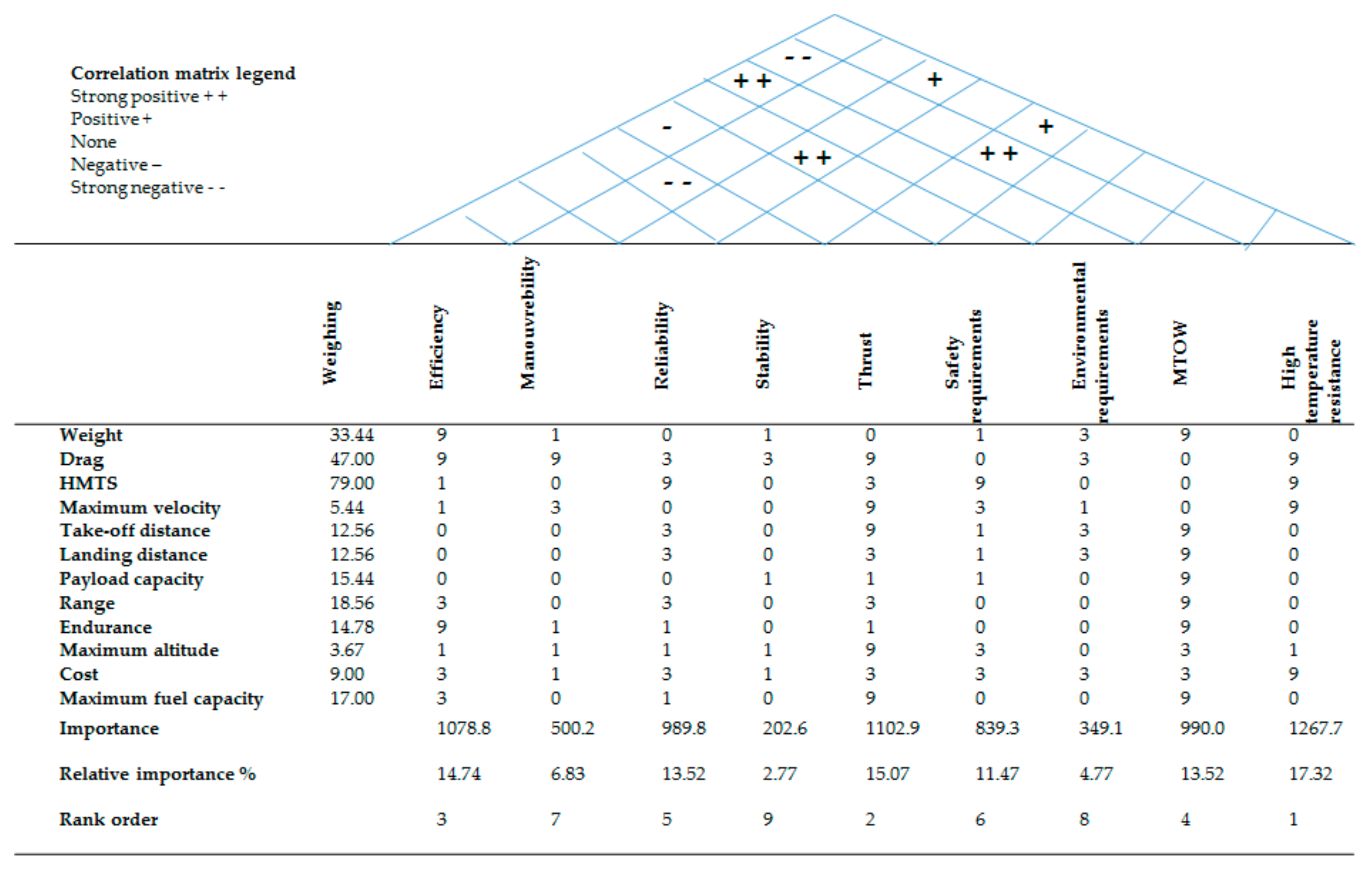
Figure 5.
House of Quality analysis.
Figure 5.
House of Quality analysis.
Figure 6.
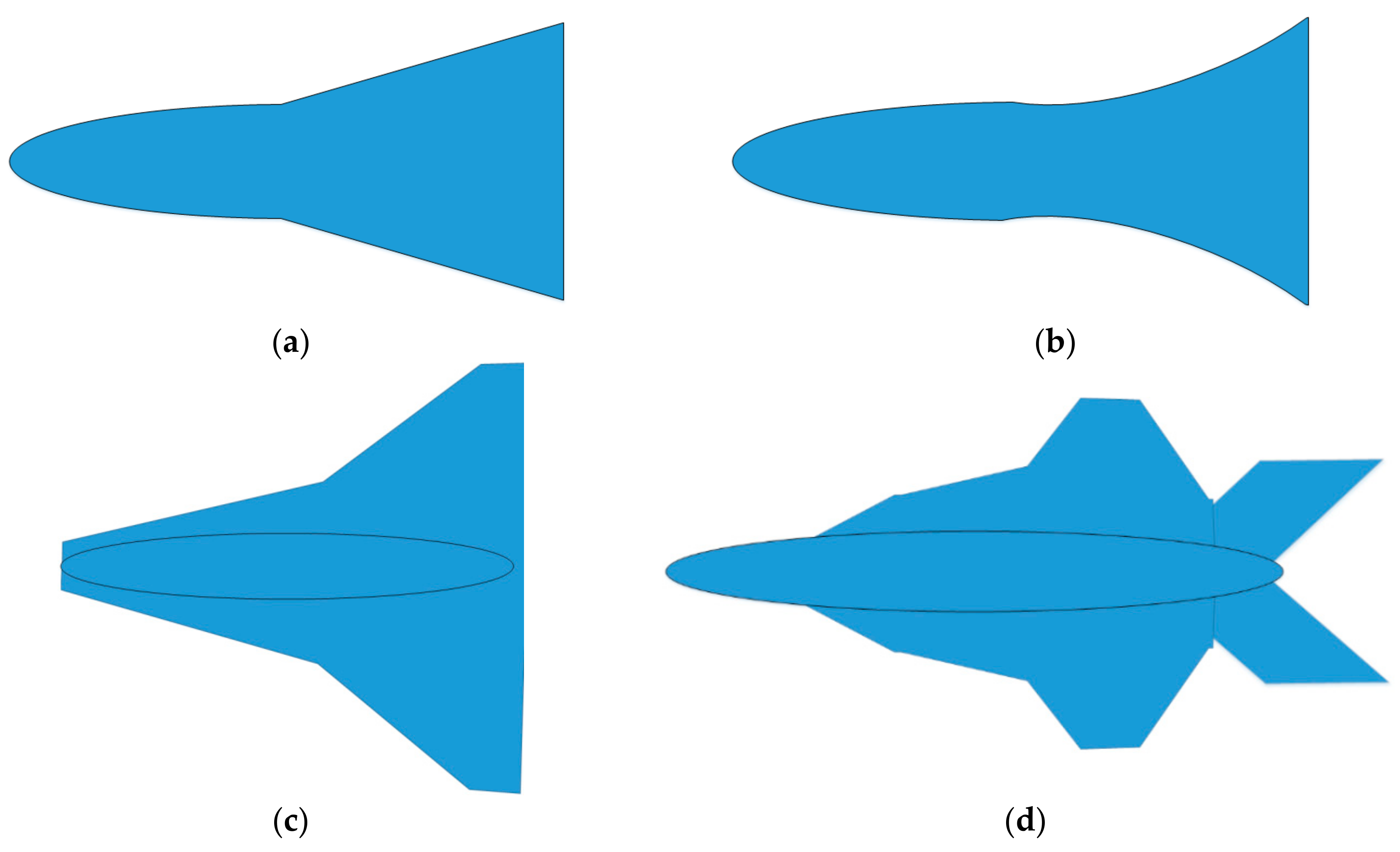
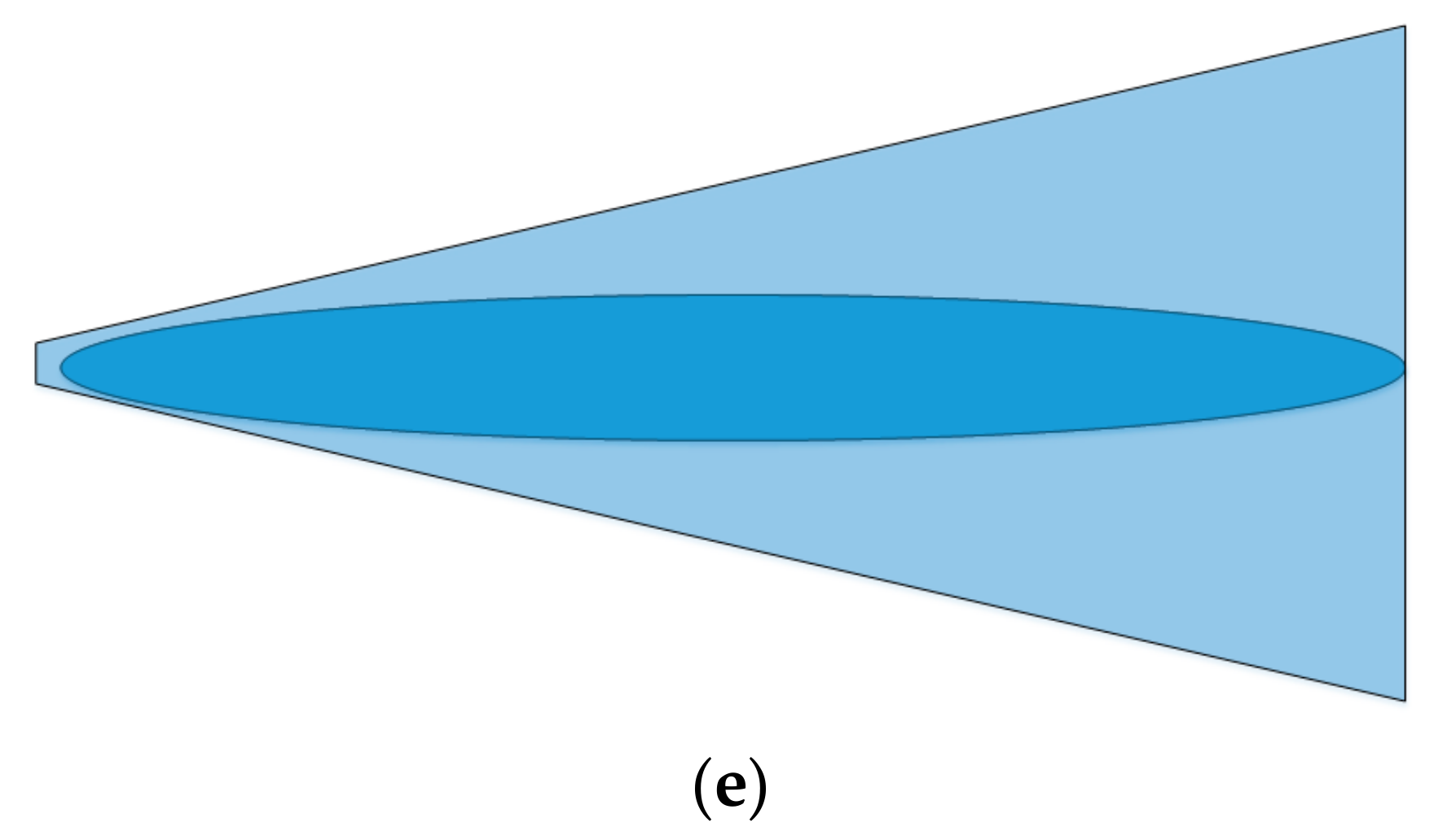
Concept sketches. (a) Concept 1; (b) Concept 2; (c) Concept 3; (d) Concept 4; (e) Concept 5.
Figure 6.
Concept sketches. (a) Concept 1; (b) Concept 2; (c) Concept 3; (d) Concept 4; (e) Concept 5.
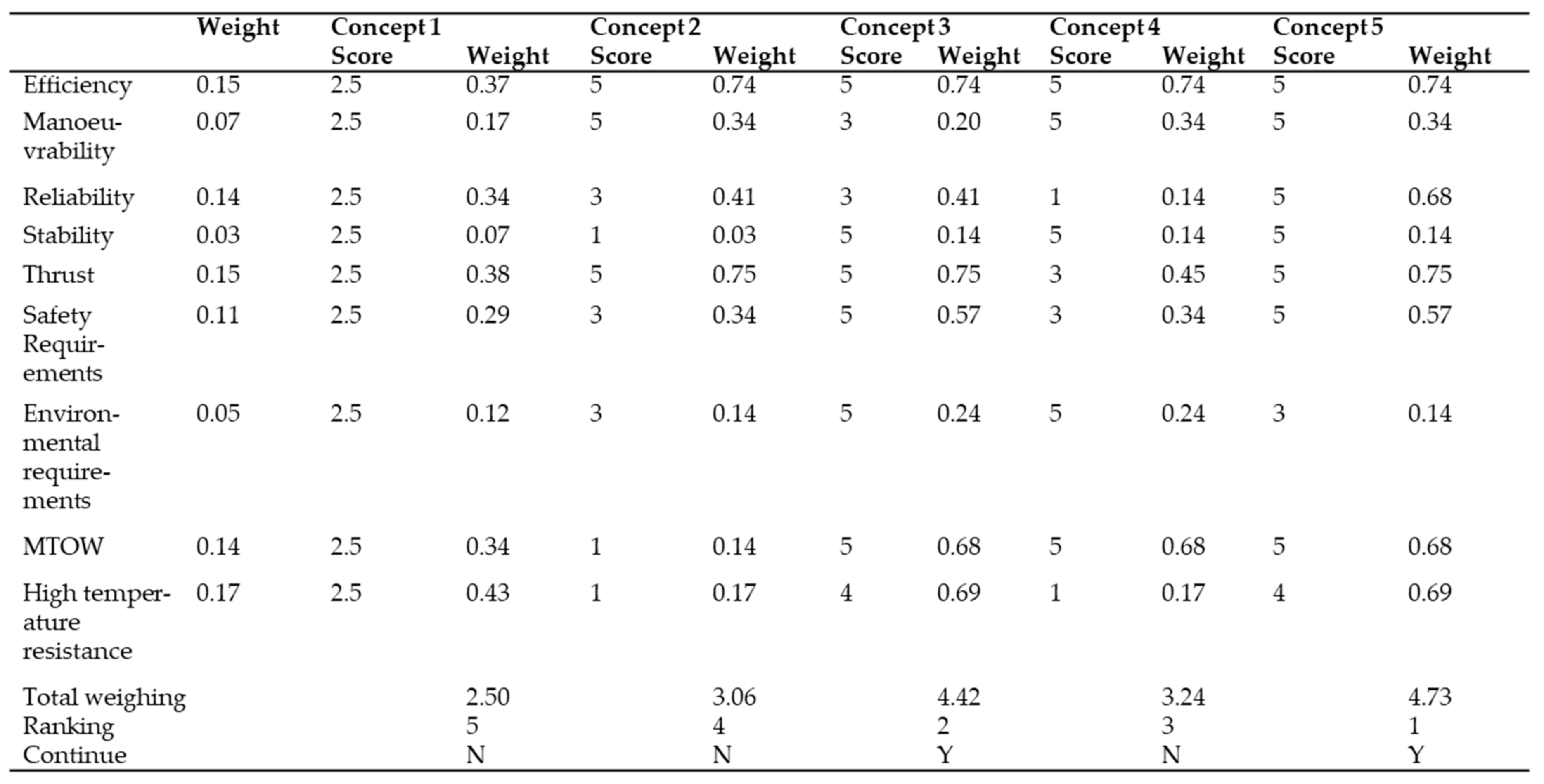
Figure 7.
Concept decision matrix.
Figure 7.
Concept decision matrix.
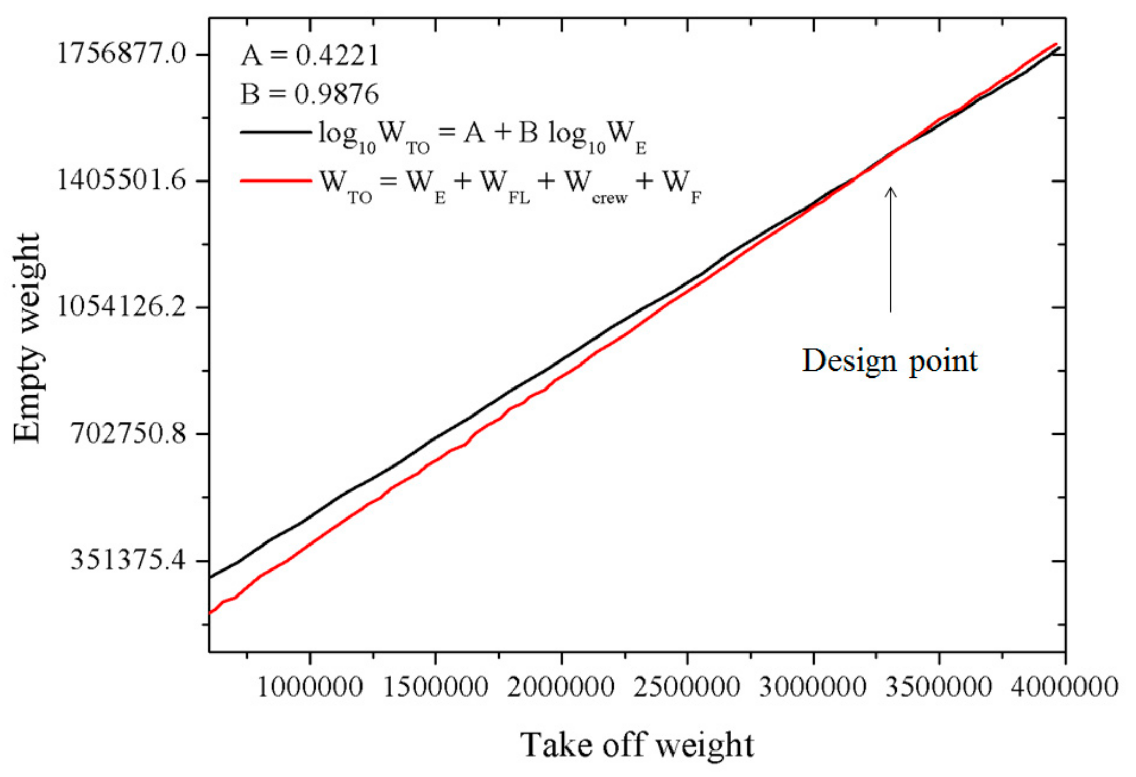
Figure 8.
Design point plot.
Figure 8.
Design point plot.
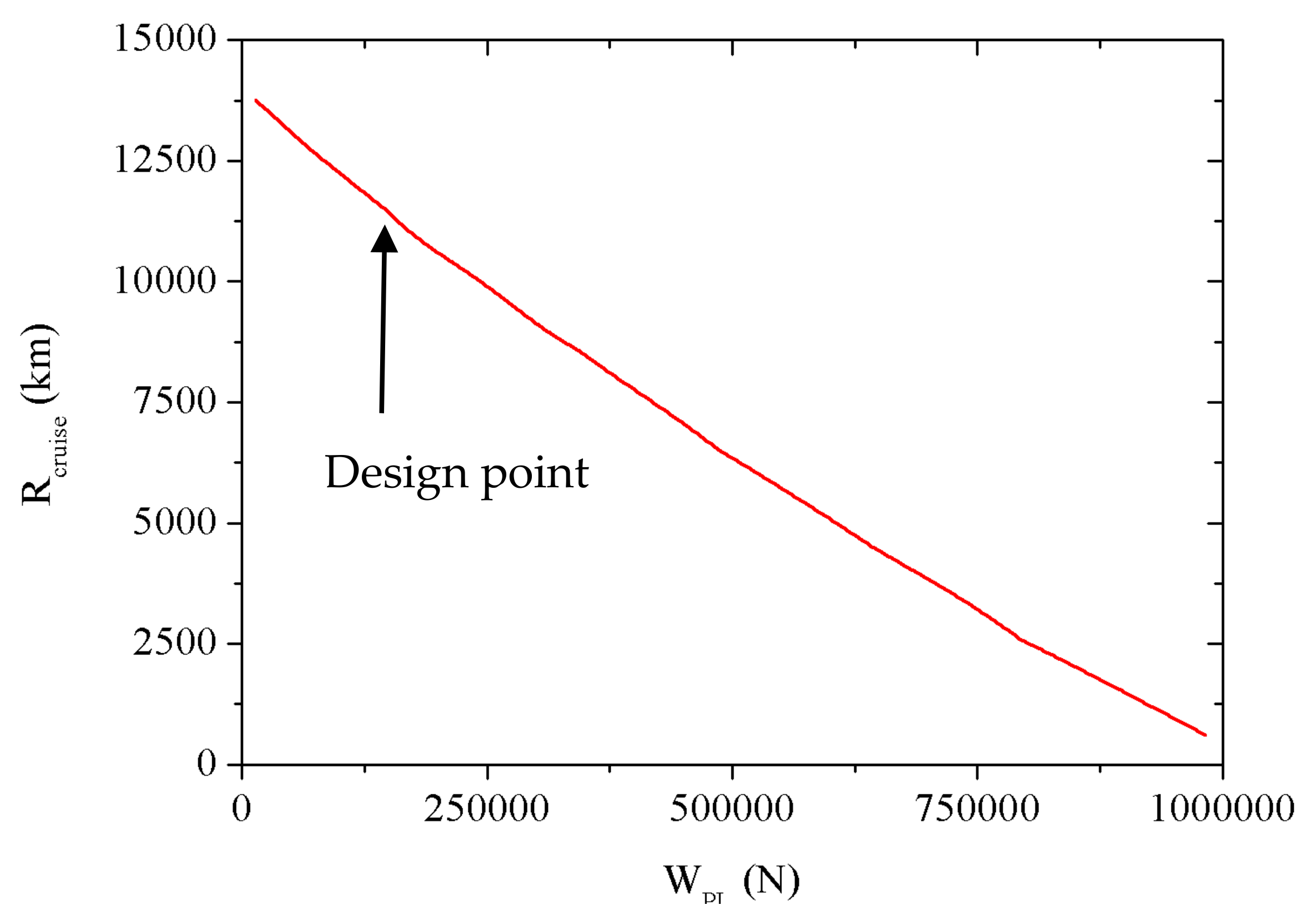
Figure 9.
Cruise range vs. payload.
Figure 9.
Cruise range vs. payload.
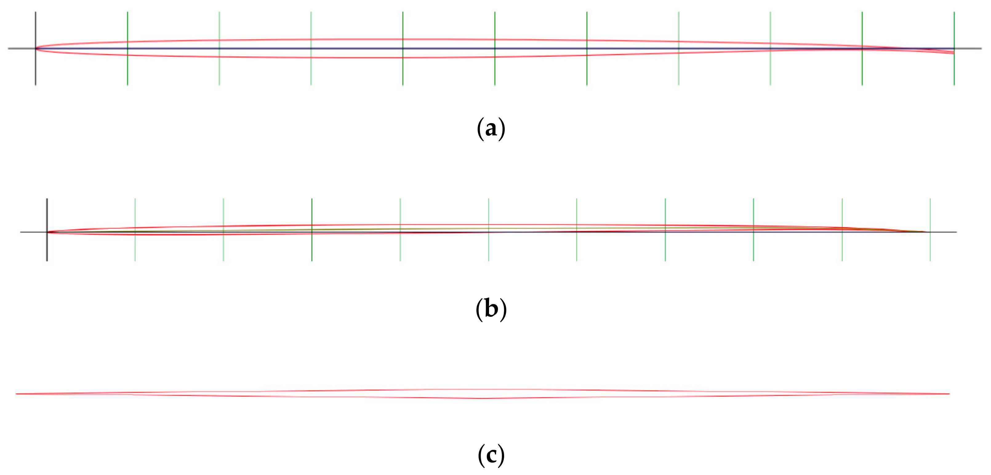
Figure 10.
(a) NASA sc(2)-0402 supercritical aerofoil; (b) NACA 0801 bespoke generated supercritical aerofoil; and (c) wedge aerofoil (1% thickness to chord ratio).
Figure 10.
(a) NASA sc(2)-0402 supercritical aerofoil; (b) NACA 0801 bespoke generated supercritical aerofoil; and (c) wedge aerofoil (1% thickness to chord ratio).
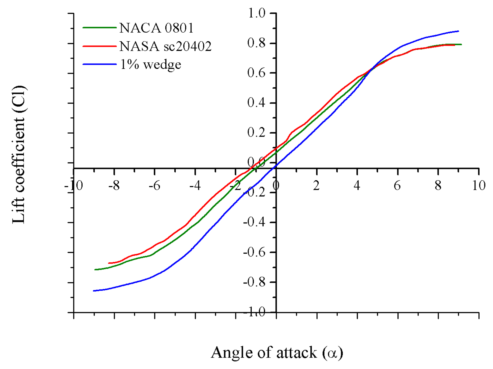
Figure 11.
Lift coefficient vs. angle of attack.
Figure 11.
Lift coefficient vs. angle of attack.
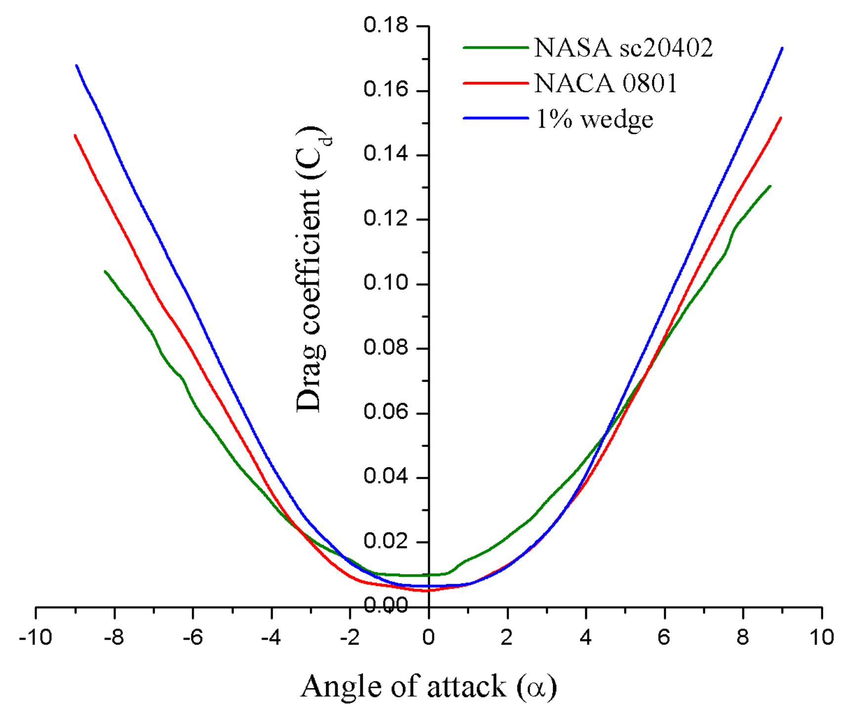
Figure 12.
Cd vs. angle of attack.
Figure 12.
Cd vs. angle of attack.
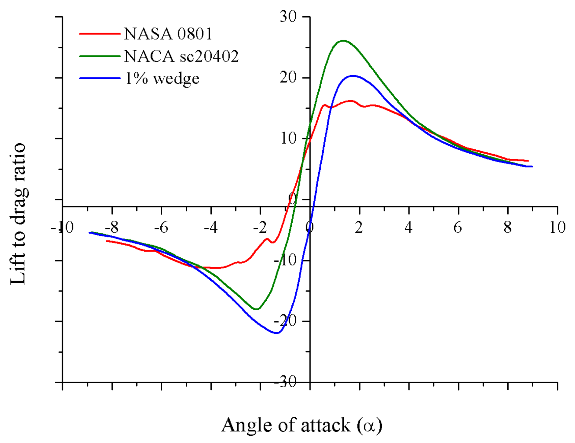
Figure 13.
CI/Cd vs. angle of attack.
Figure 13.
CI/Cd vs. angle of attack.
Figure 14.
NACA 0801 aerofoil at Mach 2.
Figure 14.
NACA 0801 aerofoil at Mach 2.
Figure 15.
NACA 0801 aerofoil at Mach 7.
Figure 15.
NACA 0801 aerofoil at Mach 7.
Figure 16.
(a) Double delta configuration; (b) Ogival delta configuration; and (c) Straight delta configuration.
Figure 16.
(a) Double delta configuration; (b) Ogival delta configuration; and (c) Straight delta configuration.
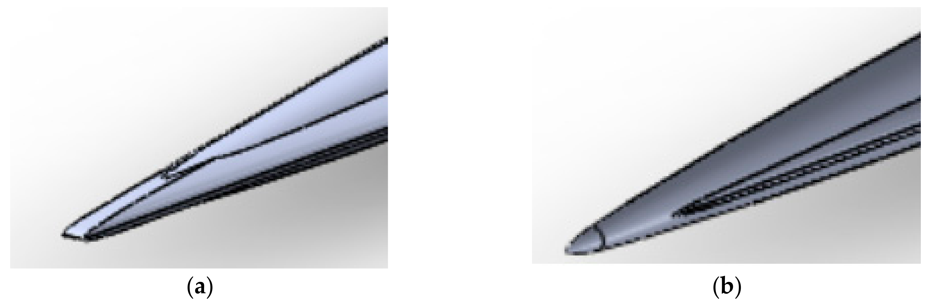
Figure 17.
(a) Blunted nose; and (b) nose cone.
Figure 17.
(a) Blunted nose; and (b) nose cone.
Figure 18.
Cd vs. Mach number for different wing configurations.
Figure 18.
Cd vs. Mach number for different wing configurations.
Figure 19.
Drag coefficients for different leading delta sweep angles.
Figure 19.
Drag coefficients for different leading delta sweep angles.
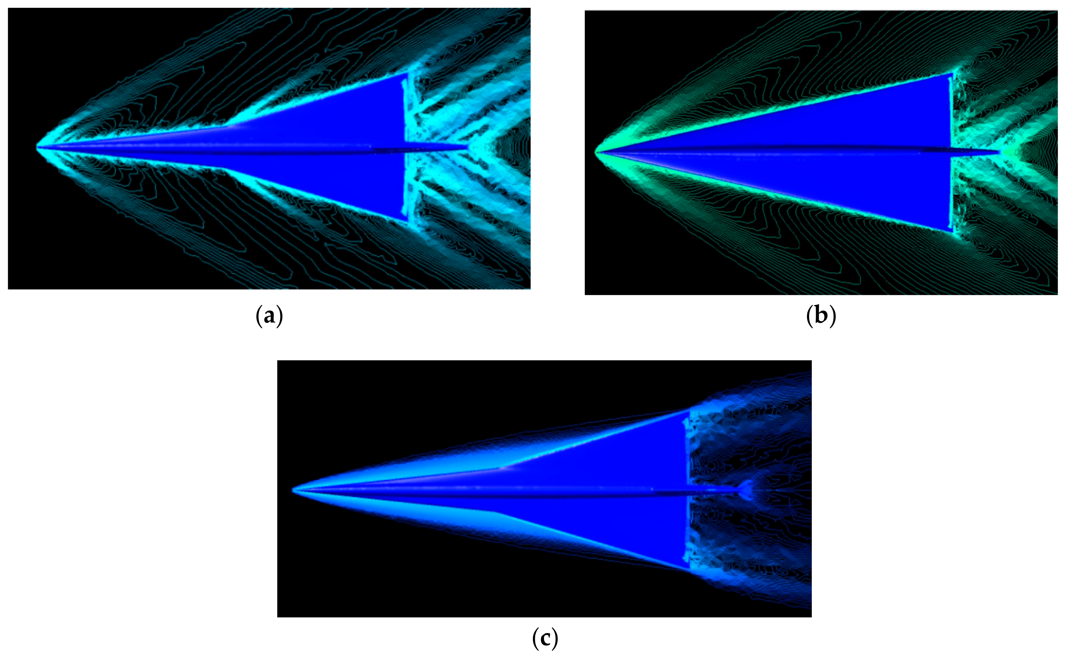
Figure 20.
(a) Contour plot of the double delta-configured aircraft at Mach 2; (b) contour plot of the straight delta-configured aircraft at Mach 8; and (c) contour plot of the double delta-configured aircraft at Mach 8.
Figure 20.
(a) Contour plot of the double delta-configured aircraft at Mach 2; (b) contour plot of the straight delta-configured aircraft at Mach 8; and (c) contour plot of the double delta-configured aircraft at Mach 8.
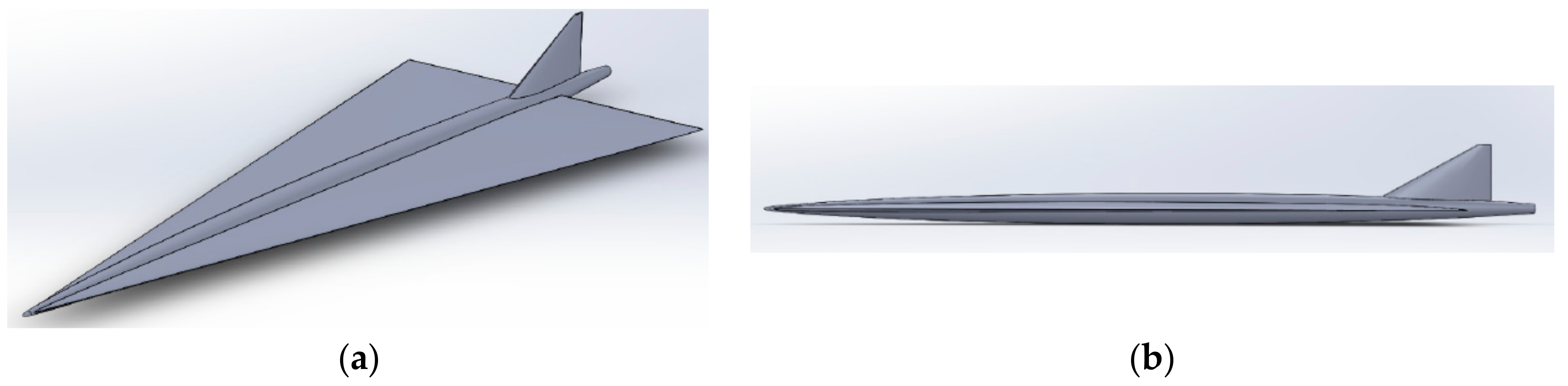
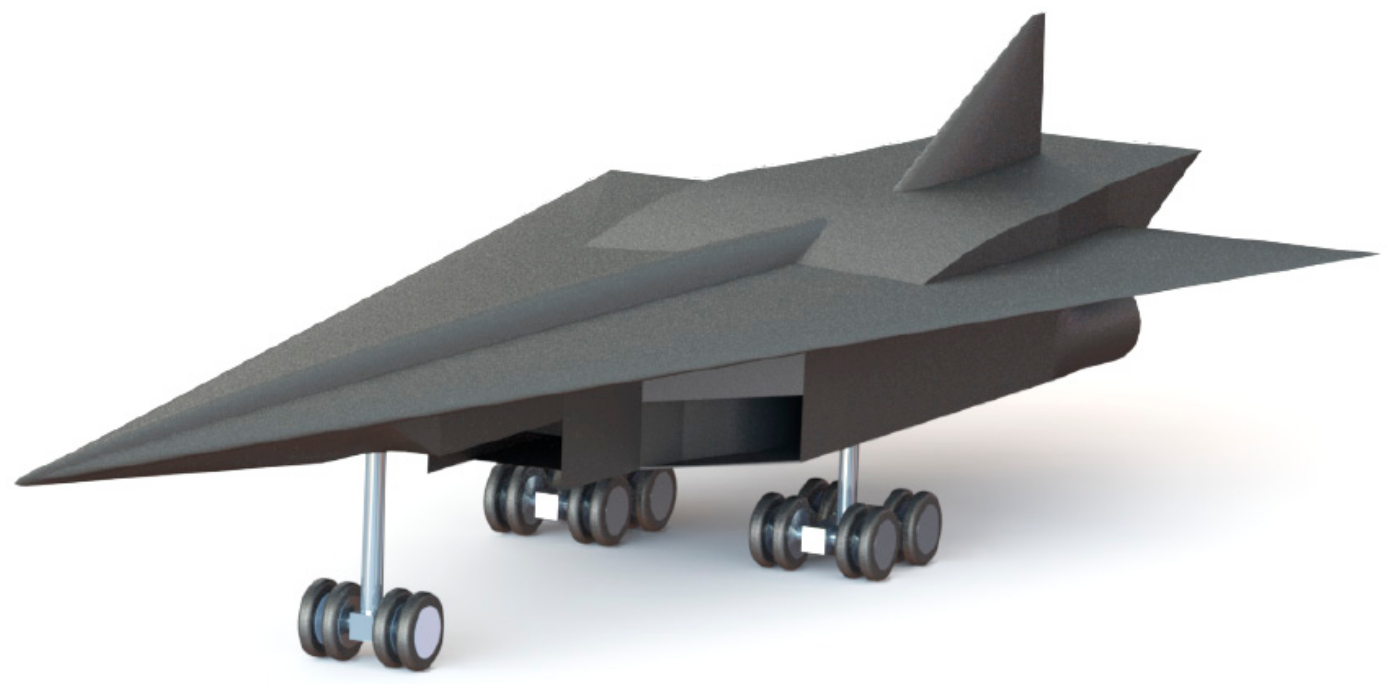
Figure 21.
(a) Isometric view of the final straight delta wing aircraft concept; and (b) side view of the final straight delta wing aircraft concept.
Figure 21.
(a) Isometric view of the final straight delta wing aircraft concept; and (b) side view of the final straight delta wing aircraft concept.
Figure 22.
Final conceptual aircraft with the integrated engine.
Figure 22.
Final conceptual aircraft with the integrated engine.
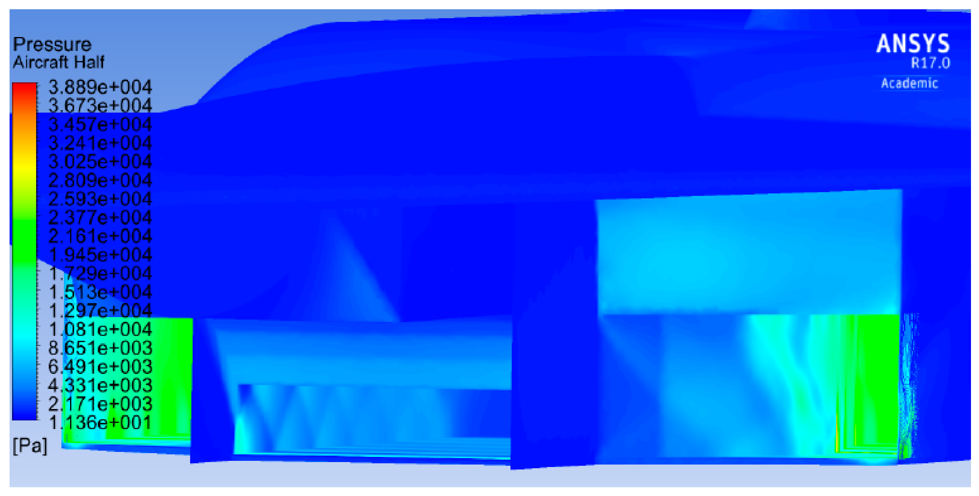
Figure 23.
Shock train inside the scramjet at Mach 4.
Figure 23.
Shock train inside the scramjet at Mach 4.
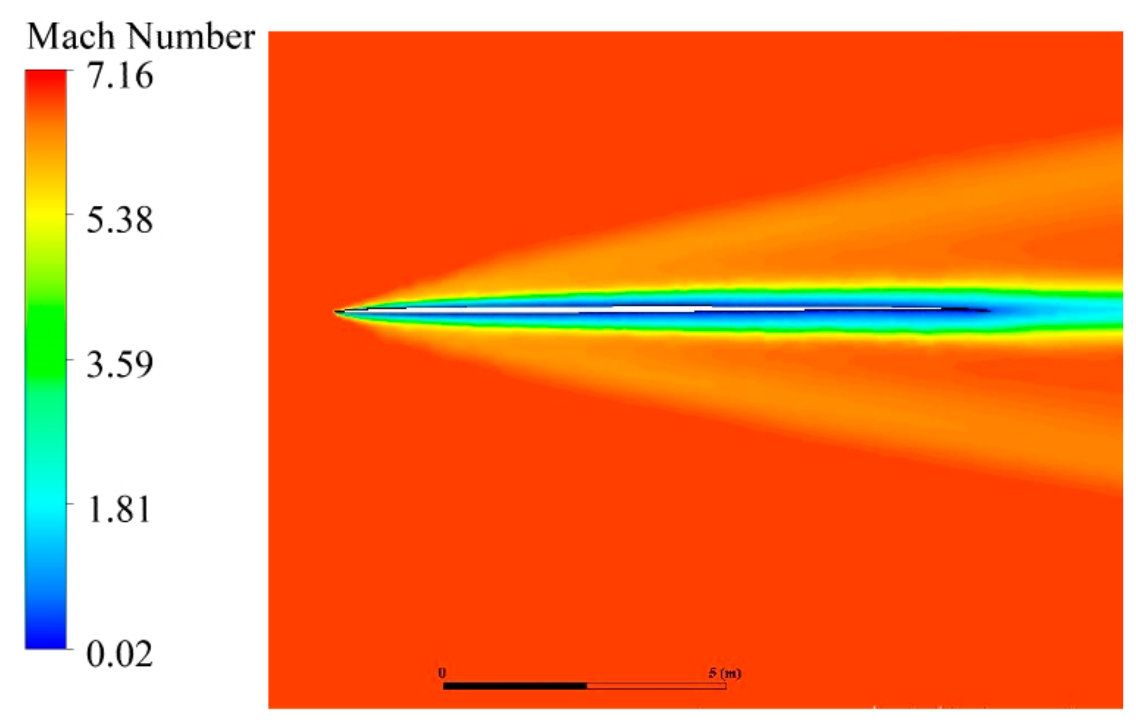
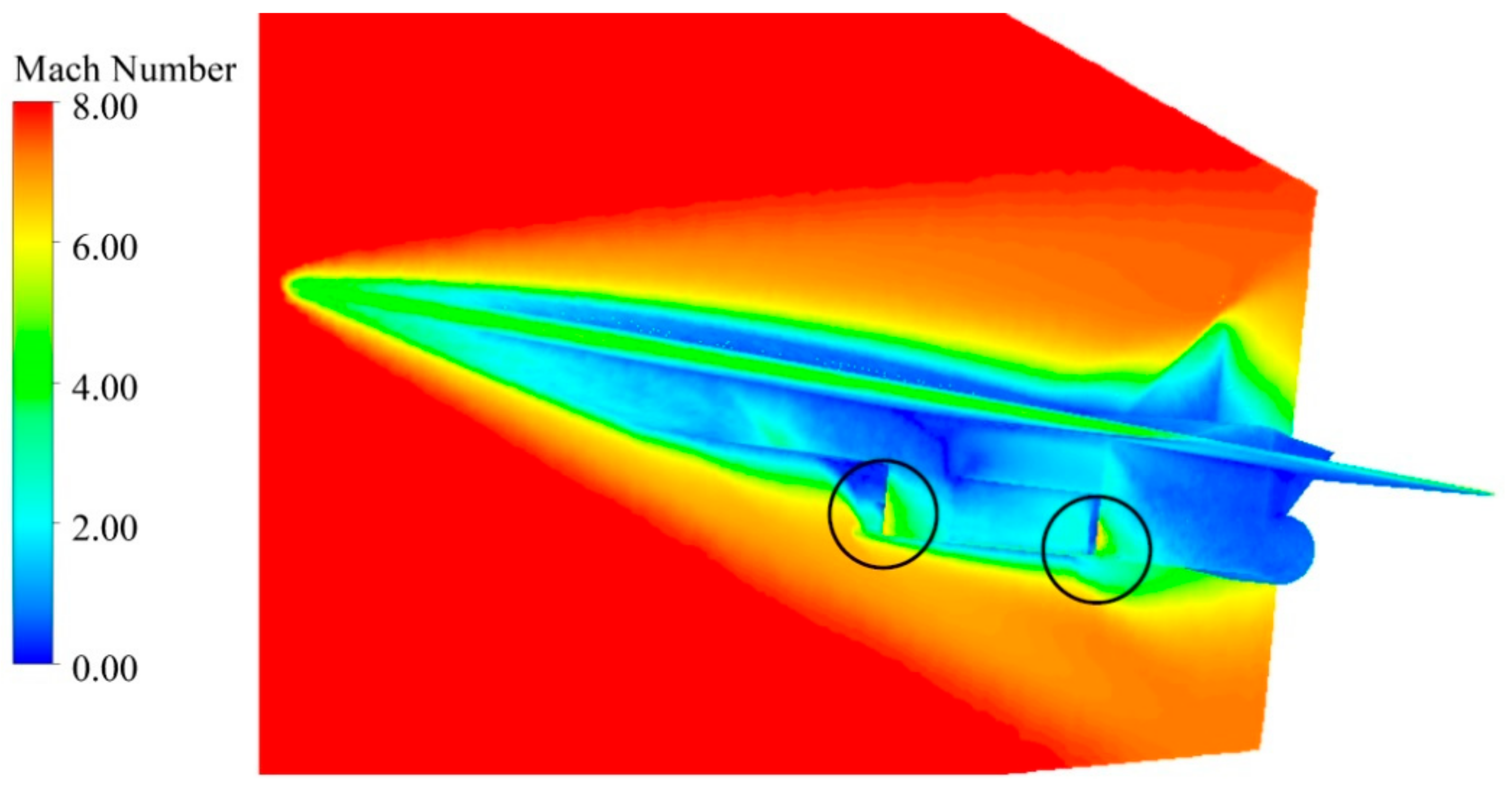
Figure 24.
Mach number contour of the aircraft at Mach 8.
Figure 24.
Mach number contour of the aircraft at Mach 8.
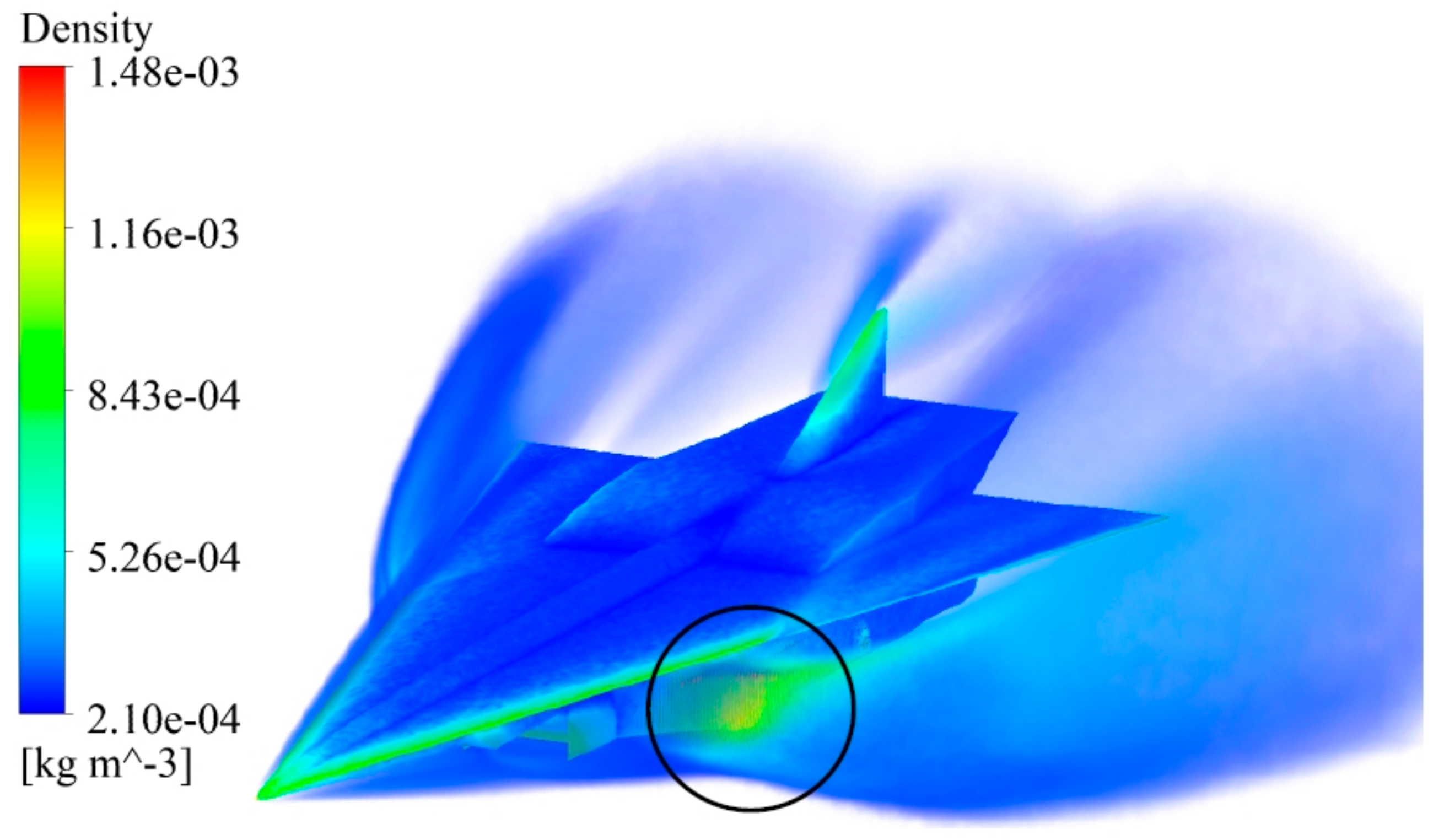
Figure 25.
Density volume rendering of the aircraft with the ramjet sealed off.
Figure 25.
Density volume rendering of the aircraft with the ramjet sealed off.
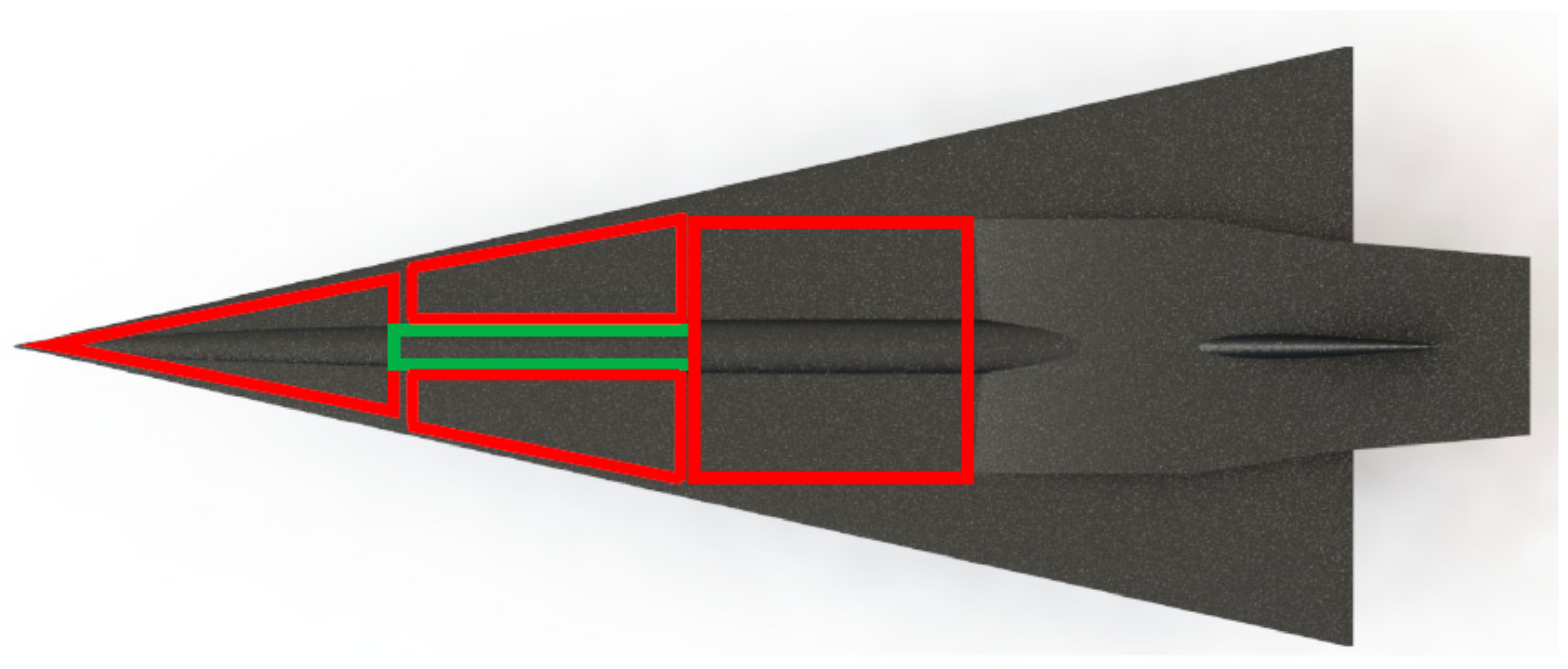
Figure 26.
Concept aircraft layout of the fuel tanks and passenger cabin.
Figure 26.
Concept aircraft layout of the fuel tanks and passenger cabin.
Figure 27.
Landing gear locations.
Figure 27.
Landing gear locations.
Figure 28.
Effect of tire pressure and tire loads on LCN.
Figure 28.
Effect of tire pressure and tire loads on LCN.
Table 1.
3-D mesh statistics for the integrated aircraft and engine.
Table 1.
3-D mesh statistics for the integrated aircraft and engine.
| Elements | 5,591,991 |
| Average skewness | 0.215 |
| Average orthogonal quality | 0.866 |
Table 2.
Comparison of CFD results with shockwave theory for Mach 2.
Table 2.
Comparison of CFD results with shockwave theory for Mach 2.
| Physical Property | Shockwave Theory | CFD Results | Error % |
|---|
| M2 (Mach number after shock) | 1.564 | 1.54 | 1.5% |
| P2 (Pressure after shock) | 25,299.8 Pa | 25,675.24 Pa | 1.48% |
| T2 (Temperature after shock) | 276.032 K | 278 K | 0.71% |
| Shock angle | 42 | 42 | 0% |
Table 3.
Comparison of CFD results with shockwave theory for Mach 8.
Table 3.
Comparison of CFD results with shockwave theory for Mach 8.
| Physical Property | Shockwave Theory | CFD Results | Error % |
|---|
| M2 (Mach number after shock) | 5.54 | 5.12 | 7.58% |
| P2 (Pressure after shock) | 0.7951 Pa | 0.76 Pa | 4.41% |
| T2 (Temperature after shock) | 478.52 K | 450 K | 5.96% |
| Shock angle | 18 | 20 | 10% |
Table 4.
Mission fuel fractions.
Table 4.
Mission fuel fractions.
| Mission Fuel Fractions |
|---|
| Mission profile | Mff |
| Warm up | 0.9900 |
| Taxi | 0.9950 |
| Take-Off | 0.9950 |
| Climb | 0.8119 |
| Cruise | 0.6538 |
| Descent | 0.9850 |
| Land/Taxi | 0.9920 |
Table 5.
Weights of individual components.
Table 5.
Weights of individual components.
| Component | Fw | Westimate N | ∆W N | Weight N |
|---|
| Fuselage | 0.077 | 234,987.0 | 4030.8 | 239,017.8 |
| Wing | 0.109 | 333,661.2 | 5723.3 | 339,384.5 |
| Empennage | 0.011 | 34,586.8 | 593.3 | 35,180.1 |
| Landing gear | 0.037 | 113,933.1 | 1954.3 | 115,887.4 |
| Nacelle | 0.019 | 56,966.5 | 977.2 | 57,943.7 |
| Structure | 0.253 | 774,134.6 | 13,278.9 | 787,413.5 |
| Power plant | 0.123 | 375,368.8 | 6438.8 | 381,807.6 |
| Fixed Equipment | 0.094 | 286,867.2 | 4920.7 | 291,787.9 |
| Empty Weight | 0.470 | 1,436,370.7 | 24,638.3 | 1,461,009.0 |
Table 6.
Design parameters of the final aircraft concept.
Table 6.
Design parameters of the final aircraft concept.
| Wingspan | 35.52 m |
| Root chord | 80 m |
| Tip chord | 2 m |
| Mean aerodynamic chord distance (from nose) | 53.37 m |
| Taper ratio | 0.025 |
| Sweep angle of wing leading edge | 77.34 degrees |
| Wing wetted area | 1456.32 m2 |
| Aspect ratio | 0.87 |
| Vertical stabilizer surface area | 47.3 m2 |
| VS Root chord | 12.78 m |
| VS Tip chord | 1.5 m |
| VS Sweep angle | 61.7 degrees |
| Total aircraft length | 90.72 m |
| Aircraft nose flow deflection angle | 12.66 degrees |
Table 7.
CFD results of aircraft integrated with engine.
Table 7.
CFD results of aircraft integrated with engine.
| | Ramjet Sealed Off | Flight Speed | Cd | Cl | Cm | Drag Force |
|---|
| Case 1 | No | Mach 4 | 0.05 | −0.0062 | 0.77 | 2.35 |
| Case 2 | No | Mach 8 | 0.057 | 0.00424 | −0.109 | 4.825 |
| Case 3 | Yes | Mach 8 | 0.032 | 0.015 | −0.63 | 2.71 |
Table 8.
Airport runway details.
Table 8.
Airport runway details.
| Airport | Runway Code | Information |
|---|
| J.F.K | 13/31 L | LCN—94 Length—4423 m Surface type—Concrete |
| Heathrow | 09 R/27 L | LCN—83 Length—3902 m Surface type—Asphalt |
| Sydney | 16 R/34 L | LCN—67 Maximum tire pressure—217 psi Length—3962 m Surface type—Asphalt |


