Abstract
Reducing losses in the secondary air system of gas and steam turbines can significantly increase the efficiency of such machines. Meanwhile, brush seals are a widely used alternative to labyrinth seals. Their most valuable advantage over other sealing concepts is the very small gap between the sealing package and the rotor and thus reduced leakage mass flow. This small gap can be achieved due to the great radial flexibility without running the risk of severe detrimental deterioration in case of rubbing. Rubbing between rotor and seal during operation might occur as a result of e.g., an unequal thermal expansion of the rotor and stator or a rotor elongation due to centrifugal forces or manoeuvre forces. Thanks to the flexible structure of the brush seal, the contact forces during a rubbing event are reduced; however, the frictional heat input can still be considerable. Particularly in aircraft engines with their thin and lightweight rotor structures, the permissible material stresses can easily be exceeded by an increased heat input and thus harm the engine’s integrity. The geometry of the seal has a decisive influence on the resulting contact forces and consequently the heat input. This paper is a contribution to further understand the influence of the geometrical parameters of the brush seal on the heat input and the leakage during the rubbing of the seal on the rotor. In this paper, a total of three seals with varied back plate inner diameter are examined in more detail. The experimental tests were carried out on the brush seal test rig of the Institute of Thermal Turbomachinery (ITS) under machine-relevant conditions. These are represented by pressure differences of 1 to 7 bar, surface speeds of 30 to 180 m/s and radial interferences of 0.1 to 0.4 mm. For a better interpretation, the results were compared with those obtained at the static test rig of the Institute of Jet Propulsion and Turbomachinery (IFAS) at the Technical University of Braunschweig. The stiffness, the blow-down and the axial behaviour of the seals as a function of the differential pressure can be examined at this test rig. It could be shown that the back plate inner diameter has a decisive influence on the overall operating behaviour of a brush seal.
1. Introduction
Radial adaptive seals like brush seals offer the possibility to reduce the internal leakage in turbomachines considerably, in particular in comparison with labyrinth seals. Consequently, the behaviour and the sealing effect of brush seals have been the focus of research for more than 20 years. Depending on the sealing effort, the brush seal has to become more robust in order to stabilise the bristles at a higher pressure drop like e.g., for steam turbine applications. In addition, it should be more flexible at lower pressure drops due to a higher number of start cycles in the case of stationary gas turbines or jet engines. With this background, research results were published, where the relationship between the geometrical parameters and the sealing behaviour of brush seals had been investigated [,,]. As shown by Crudgington et al. [], a larger front plate diameter results in a higher leakage and a reduced compression of the bristle pack, which, on the other hand, reduces the stiffness of the bristle package. The latter can be beneficial with regard to rubbing of the seal. A larger inner diameter of the back plate or fence height (see Figure 1) results in a reduced friction between the bristle pack and the back plate as well as a reduced pressure resistance of the bristle pack. For an optimal sealing performance, it is desirable to design the gap as narrow as possible. As a result, the bristle package is optimally supported and deflection in the axial direction due to the applied pressure forces is significantly reduced. When the fence height is too large, increased leakage and gap opening, referred to as blow-down, can be observed.
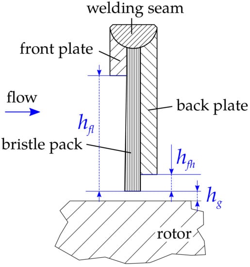
Figure 1.
General composition of a brush seal.
The publications mentioned above describe the influence of the geometrical parameters on the leakage and the general sealing behaviour like e.g., blow-down, but not on the heat input due to rubbing of the seal. Therefore, this paper discusses the effect of fence height on the frictional heat input due to rubbing. To interpret the results of the heat input measurements, it is necessary to understand the properties of the seals, which means the blow-down and the axial behaviour as well as the segment stiffness of the bristle pack. For this, the seals were tested in Braunschweig at the non-rotating cold air test facility to determine the general properties at pressure differences up to 4 bar. With this knowledge, the frictional heat input measured at the brush seal test rig in Karlsruhe can be evaluated.
2. Materials and Methods
The seals presented in this paper were tested at two test facilities. Initially, tests were carried out on the cold air test facility at IFAS. This facility is used to obtain detailed data with respect to the blow-down capability, the axial behaviour of the bristle pack as well as the bristle pack stiffness. Subsequently, rub tests at the brush seal test rig took place at ITS. Here, the primary objective is to determine the total frictional power loss as well as the heat input into the rotor structure during rubbing.
2.1. Cold Air Test Facility (IFAS)
The test facility can be operated at supply pressures up to 10 bar and has a non-rotating rotor, which is represented by the use of different stationary 300 mm diameter discs. The test seal itself is installed in a seal carrier, which is fixed at a pivoted centre shaft. In order to measure at different circumferential positions, the carrier can be rotated stepwise to 24 measuring points around the circumference. During the measurements, the seal carrier is fixed. The focus of this investigation is directed to brush seal quality attributes, like the bristle pack stiffness, the blow-down or the axial properties of the bristle pack. Furthermore, the test facility provides optical access from the downstream side to the bristle pack for all test arrangements, which offers the possibility to record and analyse sealing behaviour. An overview of the complete test facility is given in []. The three main settings of the test facility to analyse the brush seal behaviour are depicted in Figure 2. Case ‘A’ is used to determine the blow-down capability of the test seal. For this investigation, radial clearances between the last bristle row and the rotor disc are photographed and analysed for different pressure drops. Case ‘B’ allows for analysing the axial packing and the axial behaviour of the bristle pack. Therefore, optical access including a mirror is assembled to the rotor disc, which enables photographs or moving pictures to be taken from below at different pressures. By comparing the respective leakage flows from cases ‘A’ and ‘B’, it is ensured that the sealing properties have not changed between the test runs. A further case ‘C’, which is shown in Figure 2, is used to test the radial stiffness of a bristle pack segment. Hereby, a motor controlled movable test shoe is installed at the rotor disc including radial force and displacement sensors. To determine the package forces, the test shoe is radially moved 0.5 mm into the package. As discussed in [,], stiffness testing using a test shoe contains nonlinear end effects, which influences the determination of the absolute stiffness of a brush seal. Nevertheless, a comparison of different test arrangements is allowed since the results from different arrangements are affected by similar end effect errors. Therefore, the stiffness can be investigated and compared as a function of the seal design as well as a function of the pressure difference. A resultant force at the test shoe due to varying pressure at the front side of the shoe is measured as an offset at the beginning of the test and taken account of in the calculation of the stiffness. The stiffness itself is calculated for a displacement increment of 0.1 mm based on the maximum displacement and the corresponding force difference (see Figure 3).

Figure 2.
Main test arrangements ((A): blow-down; (B): axial behaviour of the bristle pack; (C): stiffness). Reproduced with permission from [], Copyright@ ASME, 2015.
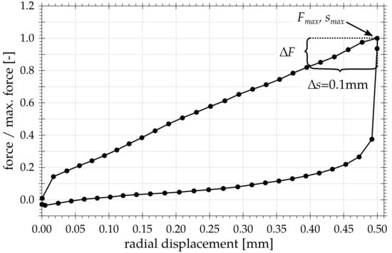
Figure 3.
Example of a general force–displacement curve for determining the stiffness.
Bristle oscillations, as observed at large back plate inner diameter, influence the measurements of the bristle pack width. As shown in [], an average width of the oscillating bristle pack can be used for this analysis. The blow-down analysis of the brush seals is free from negative impacts, since the photographed last bristles row is fixed at the back plate and free from any oscillations at pressure differences above 1 bar. The measurements of the stiffness is also not influenced by the oscillating bristle pack because the axial test shoe width is about 10 mm and covers the whole bristle pack. Repeated measurements of single seal arrangements show a very good reproducibility, also after repeated assembly.
For optical analysis of the blow-down and bristle pack width, the standard error of the mean () is given in the following relevant figures in the paper. The error bars indicate the standard error of the mean and do not include the circumferential asymmetry of the detected blow-down or axial width.
In Table 1, the relative errors are listed for the pressure measurements depending on the pressure difference. All listed errors include the entire measuring system and are referred to the effective range of the sensor in use. For the calculation of the systematic error, the square law of error propagation and the relative error of the sensors were used.

Table 1.
Relative error of the pressure measuring
2.2. Brush Seal Test Rig (ITS)
The test rig at ITS (see Figure 4) is a rotating test rig allowing for seal examinations under machine-oriented operating conditions. The target parameters of the tests on this test rig are the leakage mass flows and the heat flows while the seal is rubbed on the rotor. The experiments can be carried out at maximum pressure differences across the seal of up to 9 bar, circumferential velocities of up to 180 m/s and rotor to seal interferences of up to 0.5 mm. The interference can be adjusted both radially and concentrically. The test rig is operated with air at ambient temperature and is driven by an electric three-phase asynchronous motor. Between the driving motor and the rotor bearing, a torque transducer and a telemetry unit equipped with the receiver are installed. The telemetry unit is used to transfer the temperature data of thermocouples, embedded in the rotor structure, to the static system. The thermocouples are routed from the rotor to the transmitter unit via a hollow shaft. The rotor disk consists of Inconel 718 and has a diameter of 299.5 mm on the right front edge (see Figure 4).
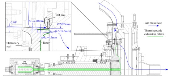
Figure 4.
Sectional view of test rig. Detail: bore hole geometry of rotor instrumentation, reproduced with permission from [], Copyright@ASME, 2017.
As mentioned above, one of the target parameters is the leakage mass flow through the tested seal. The mass flow measurement is carried out by several differential pressure metering orifices according to DIN EN ISO 5167 with nominal diameters of 32, 80 and 100 mm. Depending on the flow, the implemented control automatically switches between the three different orifices. This way, all relevant mass flows between 3–584 g/s can be measured within an accuracy of ±1.5%. A number of parameters is available for assessing the leakage behaviour of sealing systems. In this paper, the discharge coefficient was used. This value is defined by the ratio of the measured leakage flow through the seal to an idealized, inviscid gap flow:
The gap flow is defined by an isentropic nozzle flow, which can be represented by the following equation:
A is the annular gap area between the back plate and the rotor. The leakage flows of the static and secondary axial brush seals are not measured.
The other target parameters are the heat flows while rubbing. Concentric rubbing of the seal is realised by moving the housing and therefore the seal in the axial direction to the left along the conical shaped rotor. The cone angle of the rubbing surface is 2.95°. The rotor was instrumented with the primary objective of measuring the friction-related, transient rotor temperatures during the rubbing of the brush seal against the counter-surface. For this purpose, an in situ measurement of temperatures using thermocouples embedded in the rotor structure close to the rubbing surface was installed. A total of 24 (4 × 6) thermocouples of type K with a diameter of 0.5 mm are inserted into bore holes at a distance of 2.0 mm parallel to the rotor surface. The temperatures are measured at 11 different axial positions. The axial distance between the thermocouples is 1 to 2 mm. For redundancy, the temperatures of each axial position are measured at two circumferential positions displaced by 180°. At the axial measuring position of 7.5 mm away from the right rotor edge, four thermocouples are arranged circumferentially at 90° intervals for a better estimation of the temperature distribution along the circumference. To increase the heat conduction between the rotor structure and the thermocouples the bore holes are filled with a heat-conductive paste with a thermal conductivity of 3.8 W/(m K). During the investigations discussed in this paper, 19 thermocouples have remained intact. For further details of the rig, see [].
2.3. Evaluation Method
Based on the measured transient temperatures, however, it is not possible to readily deduce the desired heat input into the rotor structure. Since the assumption of a thermally thin body is not valid in this case, both the local and the temporal temperature gradients must be taken into account. Moreover, the geometry of the experimental set-up is too complex to solve the problem with applying analytical equations. For this reason, a numerical model for of a finite element analysis was chosen.
The numerical model was built as a 2-dimensional, axisymmetric model representing the rotor and a part of the shaft. The modelled parts are shown in Figure 5. All non-symmetrical areas of the rotor, in particular the screw connection to the shaft, were assumed to not be influenced thermally during the 30 s of rubbing. They were nevertheless modelled to correctly calculate the displacements of the rubbing surface due to rotational forces. To justify the simplification of a 2D-model, a comparison with a 3D-model was made. A mesh-independency study was also carried out. The model was set up as a thermomechanically coupled model to calculate both the mechanical and thermal deformations. This is necessary because the value of the set interference was corrected with the value of the thermal and mechanical expansion during rubbing. The convective heat transfer was considered along the dashed line shown in Figure 5. The convective heat transfer coefficients were calculated with analytical correlations according to []. On all non-marked surfaces, adiabatic conditions were assumed. The heat input itself was specified as a boundary condition in the model. It was iteratively varied until there was a satisfactory agreement between the temperatures of experiment and numerical simulation. In doing so, the temperature sensors, which are located closer to the heat input surface, were weighted more strongly in the correction procedure of the heat input. The white points highlighted in Figure 5 represent the temperature measurement locations in the experiment. In order to quantify the influence of the external boundary conditions and the bore tolerances on the temperature measurement as well as the subsequent calculation of the heat input, a sensitivity analysis was carried out. The results of this analysis are summarized in [].
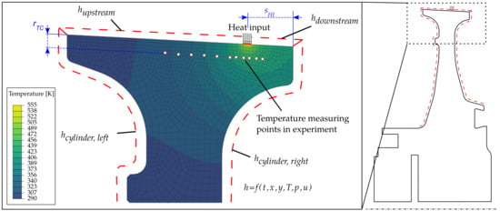
Figure 5.
2D finite element model.
2.4. Repeatability of the Measurements
When carrying out a rub test with brush seals, it is of vital importance to ensure that the initial position before each rub test is as equal as possible. This is true in particular for the bristle package. On the one hand, the exact knowledge of the current seal and rotor diameter, corresponding to the current state of wear, is required, on the other hand, the package must be brought to a state, which was as unaffected as possible by the previous rub test. The former condition is achieved by measuring the inner diameter of the bristle package after each parameter variation (differential pressure, speed or interference), i.e., after no more than 4–5 rubbing cycles, using a 2D profile laser scanner. Using the diameter measurements, the wear is interpolated linearly and the wear is associated with the respective rub test. Both with the diameter measurement outside the test rig and when the seal is installed, it must be ensured that the bristles do not remain in a radially deflected position, for example because of the friction on the back plate. In order to ensure that the bristles always reach their position of rest prior to measuring the diameter and before each rub test, two independent methods have been developed. To determine the effectiveness of the method used outside the test rig prior to measuring the diameter, 30 successive measurements were carried out with two seals. The empirical standard deviation is ±9 µm (95% confidence level). Considering a measuring accuracy of the 2D profile laser scanner and the error of measuring the rotor diameter, the desired interference can be determined with an accuracy of ±0.019 mm. When installed in the rig, the procedure requires to “loosen” the bristles after the first rub test with a rod and thus to separate potentially stuck or welded bristles. In addition, an automated process is applied using pressure shocks to minimize hysteretic effects. After this confirmation, the actual rub test can begin. For further details about actual single rub tests, see [].
2.5. Investigated Seals and Test Parameters
The experimental results discussed in this paper are based on three welded type seals. The variation of the back plate inner diameter was carried out within stages of 303, 305 and 307 mm (see Figure 1 right). Based on a rotor diameter of 300 mm and zero interference this corresponds with fence heights of 1.5, 2.5 and 3.5 mm, respectively. All other geometry parameters are kept identical. The geometry parameters are listed in Table 2.

Table 2.
Seal parameters.
The test parameters of the experiments at the IFAS test rig and at the ITS test rig, respectively, are summarized in Table 3.

Table 3.
Test parameters.
3. Results and Discussion
A special focus will be on the results of rotor heat input and total frictional power loss during rubbing of the seal. However, in order to explain the differences between the seals, it is indispensable to refer to experimental data gained at the stationary test rig of the Institute of Jet Propulsion and Turbomachinery. Furthermore, results of leakage data describing the hysteresis behaviour of the tested seals as a result of the rubbing are essential part of the discussion.
3.1. Generation and Distribution of Rubbing Heat
The total frictional power loss is obtained by subtracting the motor power during rubbing from the power before rubbing. The speed remains almost constant during a rub test. However, a slight reduction in speed at the beginning of the rubbing could not be completely avoided. The total power loss was corrected accordingly by adding the power to decelerate the rotor and subtracting the power to accelerate the rotor to the initial value. The heat flux distribution is obtained as the ratio of rotor heat input calculated by means of the finite element analysis and the measured total frictional power loss:
The measurement accuracy for calculating the total frictional power loss is within ±0.123% and negligible. However, the deviations of the total frictional power losses and rotor heat inputs of the various measurement passes are much larger (see Figure 6, Figure 11 and Figure 12). One of the reasons for this is that, despite applying different procedures to bring the bristle package back to its resting position, there is still a small variance left, which may explain the deviation of the interference (see above). To qualify the deviations, the standard deviations for reference conditions were calculated. For reasons of confidentiality, not all operating parameters for the reference conditions can be disclosed. In Table 4, the measurement accuracies and the standard deviations for reference conditions are listed.
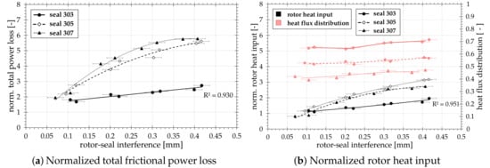
Figure 6.
Results of rub tests with varied rotor-seal interference.

Table 4.
Measurement and repeat accuracies.
3.1.1. Variation of Rotor-Seal Interference
First, the initial range of interference was varied from 0.1–0.4 mm. In Figure 6a, the average total frictional power losses are shown, while, in Figure 6b, the average rotor heat inputs and the heat flux distributions are represented. The overlap values shown in Figure 6 represent the time averaged interferences over the rubbing time, taking into account the additional thermal expansion of the rotor. In order to ensure comparability of the results, the values were normalized to the starting value of seal 2 at 0.1 mm (see authors’ previous publication [], Figure 5):
Only in the case of seal 303, a linear increase in total frictional power loss and rotor heat input with increasing interference occurs. The coefficient of determination is correspondingly very high. The seals 305 and 307 differ significantly from the linear trend, with an increased trend at a larger back plate inside the diameter. This is because the actual rotor to seal overlap is smaller than the ones that are illustrated. The interferences, shown here, are calculated on the basis of the measurement of the seal and rotor diameter taking into account the rotor elongation and thermal expansion. Additional effects as the axial deflection of the bristles when the package is pressurised or the blow-down are, however, not taken into account. Due to the larger fence height, the axial deflections of the bristle packs of seals 305 and 307 are significantly more pronounced. This increase of axial deflections leads to a direct reduction of the actual interference. In this special experimental setup, the effect is enhanced by the conical rotor surface. However, this interpretation can only explain the deviations from the expected linear increase in the total frictional power loss when the interference is varied. It does not provide a reason for the partly significantly higher total frictional power losses and rotor heat inputs. The heat flux distribution decreases with increasing fence height, i.e., a smaller proportion of the heat is introduced into the rotor structure. The reason for this is the increase in leakage with the same interference and larger back plate inner diameter and, thus, an increased convective heat transport.
In order to understand why the total frictional power losses of seals 305 and 307 are higher, additional measurement data of the seals’ properties are required (see Figure 7). The measurements were carried out on the cold air brush seal test rig at the TU Braunschweig. The measurements took place before the rub tests. In Figure 7a, the blow-down behaviour of the seals is plotted versus the pressure difference. Seal 303 shows a significantly lower radial deflection of the bristles due to the higher friction on the back plate. In the first instance, this confirms the results of the rub tests, since a lower contact force is applied to the rotor due to the lower blow-down. Due to the reduced contact surface of the bristles on the back plate and thus reduced friction, seals 305 and 307 show a higher blow-down. From about 1.0 bar pressure difference onward, the values of seal 307 are lower than those of seal 305, although the contact surface has been further reduced. It should be noted that the radial component of the deflection is lower, the axial component, however, higher. This is clearly visible in Figure 7b. Here, distance between the last downstream bristle row and the back plate inner side is shown. It becomes clear that the axial deflection of the bristles increases with increasing pressure difference and a larger inner diameter of the back plate. In the case of seals 305 and 307, there is a significant blow-over. The bristle package of seal 303 is supported very well in axial direction and thus hardly bends. Attention should also be paid to the bristle rows of seals 305 and 307, which are already plastically deformed by approximately 0.3 mm. However, the deformations are limited to the last rows of bristles.
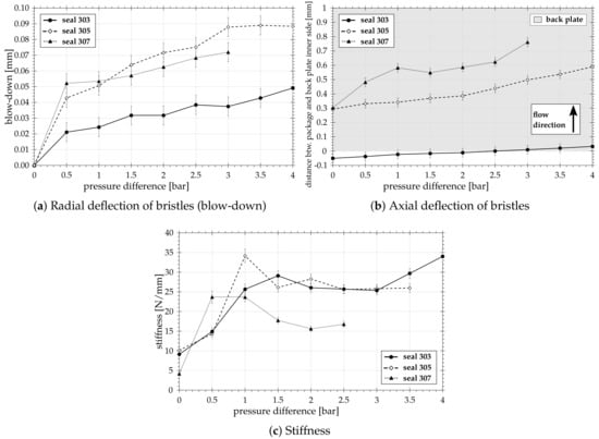
Figure 7.
Test results from the static test rig.
However, the main reason for the different heat inputs can be explained by the stiffness measurements (see Figure 7c). While seal 303 tends to stiffen with increasing pressure difference, the stiffness values of seals 305 and 307 decrease above 1.0 bar pressure difference. Photographs showing the bristle package from below indicate that the bristles of seals 305 and 307 are excited to oscillate above a pressure difference of 1.0 bar. The pictures in Figure 8 show this trend for seal 307. In these investigations, there was a gap of 0.1 mm between the package and the rotor in the unpressurised state. In Figure 8a, the bristles are displayed at a pressure difference of 1.0 bar. In this operating condition, the bristles do not yet oscillate. If the pressure is increased by another 0.5 bar (see Figure 8b), the bristles begin to oscillate starting from the centre of the package. In Figure 8c, the whole package oscillates. In Figure 8d, the oscillating bristles of seal 305 are exemplarily shown at a pressure difference of 1.5 bar.
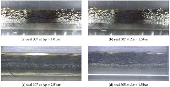
Figure 8.
Photographs of bristle packages at circumferential position 0°.
For a rub test of seal 303, this means that the bristles are deflected outwardly in radial direction at the beginning of the rubbing and remain in this position due to the increased friction. As a result, the contact forces of the bristles on the rotor and, thus, the friction losses are lower. For operating conditions with low interference or high pressure differences, even a decrease in rotor temperatures during rubbing is possible (see Figure 9). In these cases, the friction clearly outweighs the spring restoring forces of the bristles. In the case of seals 305 and 307, a continuous increase in temperature is always measured (see Figure 9).
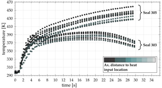
Figure 9.
Comparison of rotor temperatures for seals 303 and 305 at 4.0 bar.
The slight out-of-roundness of the rotor or rather the eccentricity of the axis of rotation of approx. 12–13 µm also provokes the bristle forces not being constant over the entire circumference and the bristles, especially in the case of stiff bristle packages, such as the one of seal 303, are deflected again each rotor rotation. This explains the large differences between the measured temperatures over the circumference of the rotor (see Figure 10a). Only when the pressure is further increased can the bristles reattach to the rotor surface and the deviations become significantly smaller (see Figure 10b). However, it can be assumed that only parts of the bristle rows reattach to the rotor, since, at higher pressure differences, as described above, the rotor temperatures may even fall again during rubbing. This means that the vast majority of bristles must remain permanently in the radially deflected position. Although the bristle packs of the seals 305 and 307 no longer oscillate during rubbing, they are still loose and movable, so that the bristles of the entire package repeatedly impinge on the rotor surface and the temperatures in the frictional contact zone increase continuously. As a result, significantly higher overall frictional power losses are being measured. Figure 10c,d confirm that the bristles rest continuously on the rotor even at low pressure differences, since the deviation of rotor temperatures over the circumference is very small.
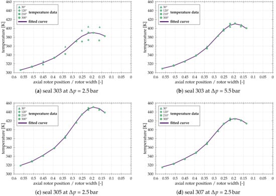
Figure 10.
Deviation of rotor temperatures.
3.1.2. Variation of Differential Pressure
In the subsequent variation of the pressure difference (see Figure 11), the maximum pressure difference for seals 305 and 307 had to be limited to 4.0 bar or 3.0 bar to prevent a plastic deformation of the bristles around the back plate. The heat inputs increase with increasing differential pressure for all tested brush seals. The increasing pressure differences cause the bristles of seal 303 to be pressed against each other and against the back plate and, as a result, the frictional forces increase. This, in turn, impedes radial deflection of the bristles during rubbing. In the case of seals 305 and 307, the effects described above apply. In addition, the differential pressure also increases the radial inward force due to blow-down. The heat flux distribution decreases with increasing fence height and pressure difference as the leakage mass flow increases and more heat is released into the air.
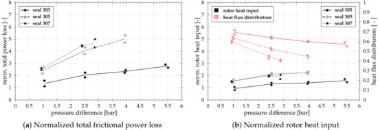
Figure 11.
Results of rub tests with varied differential pressure.
3.1.3. Variation of Circumferential Velocity
During the variation of the circumferential speed (see Figure 12), a saturation level of the heat input at higher circumferential speeds is established for seals 303 and 305. Seal 303, however, shows a slightly increased heat input at approx. 50 m/s. This is due to increased housing vibrations at this particular speed level. In fact, despite the deflected position, these vibrations cause the bristles to come consistently in contact with the rotor and, as a consequence, the temperatures increase is more pronounced. As expected, the results of the other two seals do not show such a local maximum, since the bristles always rest completely on the rotor and additional forces due to the housing vibrations over the circumference are compensated. The slope of total power loss and rotor heat input of seal 307, however, raises some questions. In particular, the pronounced maximum at a peripheral velocity of 120 m/s cannot be explained. In addition, it is still unclear how the heat input will develop at circumferential velocities above 180 m/s. A reason for the saturation states or decreases in the total power loss and rotor heat inputs at higher circumferential speeds could be the “air-riding” effect, already mentioned by several authors [,].
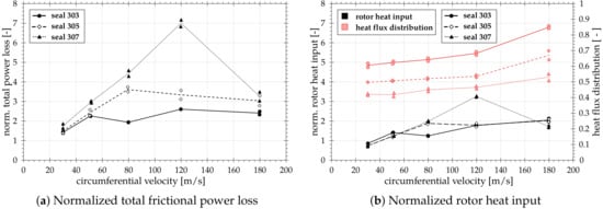
Figure 12.
Results of rub tests with varied circumferential velocity.
3.2. Leakage and Hysteresis Behaviour
During the rub tests, the leakage through the seal was also measured. With a comparison of the leakage before, during and after rubbing, the hysteresis behaviour of the seals was evaluated. The values averaged over the duration of 30 s of rubbing are plotted in Figure 13 for each varied parameter. In cases in which “no range” was specified, only one test run was used for the evaluation. This was the case when the back plate ring was not completely positioned over the rotor (see Figure 13a). A calculation of the fence height and thus of the value is therefore not possible.
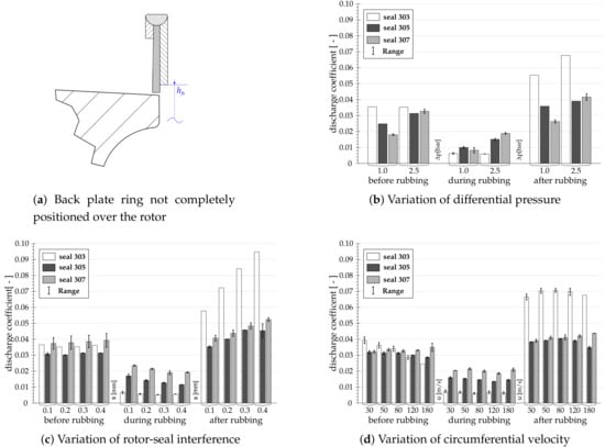
Figure 13.
Discharge coefficient for the conditions before, during and after rubbing of the seal.
In the case of the variation of the differential pressure, comparative values for all seals are only available up to a pressure difference of 2.5 bar. At 1.0 bar, an enlarged inner diameter of the back plate will have a positive effect on the leakage prior to rubbing (see Figure 13b) as the contact surface of the bristles and thus the friction is minimized and the gap is approximately closed due to the blow-down. However, if the pressure continues to increase, the seals 305 and 307 show a significant blow-over, which explains the increase in -values. Seal 303 shows no increase of the discharge coefficient at these pressure differences. The smaller contact surface, however, has a positive effect on the recovery of the bristles after rubbing. When the interference is varied (Figure 13c), these effects can also be observed. It can be seen that, after rubbing, the recovery of the bristles in their initial position decreases with increasing previous deflection. It is also interesting to note that the -values of seals 305 and 307 decrease during rubbing. This is because the fence height decreases and thus the blow-over is less pronounced. When the circumferential velocity is varied (see Figure 13d), it is remarkable that the values of seal 303 decrease before rubbing with increasing speed. If the back plate inner diameter is increased, the -values decrease less before the rubbing or, in the case of seal 307, do not vary. In absolute terms, seal 303 has a significantly lower leakage, but the hysteresis behaviour of the other two seals is much better.
4. Conclusions
As part of a cooperation between IFAS and ITS, three brush seals with different fence heights but otherwise identical geometrical parameters were tested at two test facilities. The facility at IFAS is used to obtain detailed data with respect to the blow-down capability, the axial behaviour of the bristle pack as well as the bristle pack stiffness. Subsequently, rub tests at the brush seal test rig took place at ITS. Here, the primary objective is to determine the total frictional power loss as well as the heat input into the rotor structure during rubbing. Based on the results of testing, the following conclusions are made:
- (1)
- Increasing the backing plate inner diameter causes a larger blow-down due to lower friction. However, if the diameter is increased too much, the axial deflection begins to predominate.
- (2)
- The bristles of seals 305 and 307 begin to flutter during stiffness measurements above a differential pressure of 1.0 bar. As a result, the stiffness decreases significantly. Seal 303 is very stiff and shows no bristle oscillations.
- (3)
- The bristles of the rigid seal 303 are radially deflected during the rubbing and remain in this position. The spring restoring forces of the bristles can not overcome the friction. As a result, the contact forces on the rotor and thus the heat inputs are lower.
- (4)
- The bristles of seals 305 and 307—on the other hand, they are very loose and flexible. The bristles do not remain in their deflected position. For this reason, the contact forces and heat inputs are higher.
- (5)
- The heat distribution shows that an increasing amount of heat is transferred into the air at higher differential pressures due to the increased air mass flow.
- (6)
- For two seals, a saturation level of the heat inputs is established at high circumferential speeds. An air-riding effect might be the cause for this saturation.
- (7)
- Seal 303 has consistently lower leakage rates before and during rubbing. However, the hysteresis behaviour of seals with larger fence height is significantly better.
Overall, the fence height represents an important factor, which greatly influences the properties and performance of a brush seal not only in regard to leakage, but also to the heat input and heat flux distribution.
In future measurements, it is to be checked how the heat inputs will evolve as the circumferential speed increases further to clarify whether air-riding is actually responsible for the saturation or decrease in heat input. In addition to the results on the influence of the packing density [] and the influence of the backing ring diameter shown in this paper, the influence of the axial distance of the package to the backing plate was investigated at the ITS.
Author Contributions
M.H. and H.S. conceived, designed and performed the experiments and analyzed the data. M.H. and H.S. wrote the paper. H.-J.B. and J.F. and C.S. provided guidance and feedback on the results presented in the paper and assisted with writing the manuscript.
Acknowledgments
The rub tests in this scientific publication are the result of a research project, which has been initiated by the FVV (“Forschungsvereinigung Verbrennungskraftmaschinen e.V.”) and carried out at the Institut of Thermal Turbomachinery, Karlsruhe Institute of Technology. The work has been supported financially by the FVV and the participating companies. This support is gratefully acknowledged. Special thanks go to Joris Versluis (MTU Aero Engines), who served as project chair and coordinated important technical communication between all partners. We acknowledge support by Deutsche Forschungsgemeinschaft and Open Access Publishing Fund of Karlsruhe Institute of Technology.
Conflicts of Interest
The authors declare no conflict of interest. The founding sponsors had no role in the design of the study; in the collection, analyses, or interpretation of data; in the writing of the manuscript, and in the decision to publish the results.
Nomenclature
| A | Gap area between the back plate and the rotor |
| b | Bristle pack width |
| Discharge coefficient | |
| Bristle diameter | |
| Bore hole diameter | |
| Seal inner diameter | |
| h | Heat transfer coefficient |
| Fence height | |
| Bristle free length | |
| Radial gap/interference between package and rotor | |
| Mass flow through brush seal | |
| Idealized, inviscid gap flow | |
| N | Number of individual measurements |
| p | Pressure |
| R | Specific gas constant |
| Coefficient of determination | |
| Radial distance of bore hole to rotor surface | |
| Axial distance of package to back plate | |
| Axial position of heat impact | |
| Depth of the bore hole | |
| T | Temperature |
| u | Circumferential velocity |
| Greek Symbols | |
| Heat capacity ratio | |
| Laying angle | |
| Axial inclination | |
| Packing density | |
| Standard deviation or standard error of the mean | |
| Subscripts | |
| in | Inlet |
| out | Outlet |
| t | Total |
| Abbreviations | |
| IFAS | Institut für Flugantriebe und Strömungsmaschinen (engl.: Institute of Jet propulsion and Turbomachinery) |
| ITS | Institut für Thermische Strömungsmaschinen (engl.: Institute of Thermal Turbomachinery) |
| SD | Standard deviation |
| TC | Thermocouple |
References
- Crudgington, P.F.J. Brush Seal Performance Evaluation. In Proceedings of the 34th AIAA/ASME/SAE/ASEE Joint Propulsion Conference & Exhibit, Joint Propulsion Conferences, Cleveland, OH, USA, 13–15 July 1998. [Google Scholar] [CrossRef]
- Crudgington, P.F.; Bowsher, A. Brush Seal Blow Down. In Proceedings of the 39th AIAA/ASME/SAE/ASEE Joint Propulsion Conference & Exhibit, Joint Propulsion Conferences, Huntsville, AL, USA, 20–23 July 2003. [Google Scholar] [CrossRef]
- Berard, G.; Short, J. Influence of Design Features on Brush Seal Performance. In Proceedings of the 35th AIAA/ASME/SAE/ASEE Joint Propulsion Conference & Exhibit, Joint Propulsion Conferences, Los Angeles, CA, USA, 20–24 June 1999. [Google Scholar] [CrossRef]
- Schwarz, H.; Flegler, J.; Friedrichs, J. Design Parameters of Brush Seals and Their Impact on Seal Performance. In Proceedings of the ASME Turbo Expo 2012: Turbine Technical Conference and Exposition, Copenhagen, Denmark, 11–15 June 2012; American Society of Mechanical Engineers: New York, NY, USA, 2012; Volume 6: Oil and Gas Applications; Concentrating Solar Power Plants; Steam Turbines; Wind Energy. [Google Scholar] [CrossRef]
- Bidkar, R.; Demiroglu, M.; Zheng, X.; Turnquist, N. Stiffness Measurements for Pressure-Loaded Brush Seals. In Proceedings of the ASME Turbo Expo 2011: Turbine Technical Conference and Exposition, Vancouver, BC, Canada, 6–10 June 2011; American Society of Mechanical Engineer: New York, NY, USA, 2011; Volume 5: Heat Transfer, Parts A and B. [Google Scholar] [CrossRef]
- Crudgington, P.; Bowsher, A.; Lloyd, D.; Walia, J. Bristle Angle Effects on Brush Seal Contact Pressures. In Proceedings of the 45th AIAA/ASME/SAE/ASEE Joint Propulsion Conference & Exhibit, Joint Propulsion Conferences, Denver, CO, USA, 2–5 August 2009. [Google Scholar] [CrossRef]
- Schwarz, H.; Friedrichs, J. Preliminary Investigations for a Pressure Balanced Back Plate at Low Inclined Brush Seals. In Proceedings of the ASME Turbo Expo 2015: Turbine Technical Conference and Exposition, Montreal, QC, Canada, 15–19 June 2015; American Society of Mechanical Engineers: New York, NY, USA, 2015; Volume 5C: Heat Transfer. [Google Scholar] [CrossRef]
- Schwarz, H.; Flegler, J.; Friedrichs, J. Axial Inclination of the Bristle Pack, a new Design Parameter of Brush Seals for Improved Operational Behavior in Steam Turbines. In Proceedings of the ASME Turbo Expo 2014: Turbine Technical Conference and Exposition, Düsseldorf, Germany, 16–20 June 2014; American Society of Mechanical Engineers: New York, NY, USA, 2014; Volume 1B: Marine; Microturbines, Turbochargers and Small Turbomachines; Steam Turbines. [Google Scholar]
- Hildebrandt, M.; Schwitzke, C.; Bauer, H.-J. Experimental Investigation on the Influence of Geometrical Parameters on the Frictional Heat Input and Leakage Performance of Brush Seals. In Proceedings of the ASME Turbo Expo 2017: Turbomachinery Technical Conference and Exposition, Charlotte, NC, USA, 26–30 June 2017; American Society of Mechanical Engineers: New York, NY, USA, 2017; Volume 5B: Heat Transfer. [Google Scholar] [CrossRef]
- Cardone, G.; Astarita, T.; Carlomagno, G. Heat Transfer Measurements on a Rotating Disk. Int. J. Rotating Mach. 1997, 3, 1–9. [Google Scholar] [CrossRef]
- Ruggiero, E.; Allen, J.; Demiroglu, M.; Lusted, R.M. Heat Generation Characteristics of a Kevlar Fiber Brush Seal. In Proceedings of the 43rd AIAA/ASME/SAE/ASEE Joint Propulsion Conference & Exhibit, Joint Propulsion Conferences, Cincinnati, OH, USA, 8–11 July 2007; p. 5738. [Google Scholar] [CrossRef]
- Chew, J.W.; Guardino, C. Simulation of Flow and Heat Transfer in the Tip Region of a Brush Seal. Int. J. Heat Fluid Flow 2004, 25, 649–658. [Google Scholar] [CrossRef]
© 2018 by the authors. Licensee MDPI, Basel, Switzerland. This article is an open access article distributed under the terms and conditions of the Creative Commons Attribution (CC BY) license (http://creativecommons.org/licenses/by/4.0/).