Next Article in Journal
A Shape Memory Alloy Application for Compact Unmanned Aerial Vehicles
Next Article in Special Issue
Improved Separation of Tone and Broadband Noise Components from Open Rotor Acoustic Data
Previous Article in Journal
Fixed-Wing UAV Attitude Estimation Using Single Antenna GPS Signal Strength Measurements
Previous Article in Special Issue
Validation of a Discontinuous Galerkin Implementation of the Time-Domain Linearized Navier–Stokes Equations for Aeroacoustics
 
 
Correction published on 22 December 2016, see Aerospace 2016, 3(4), 46.
Article

Theoretical and Numerical Modeling of Acoustic Metamaterials for Aeroacoustic Applications

Department of Engineering, Roma Tre University, via Vito Volterra 62, Rome 00146, Italy
Aerospace 2016, 3(2), 15; https://doi.org/10.3390/aerospace3020015
Submission received: 11 March 2016 / Revised: 12 May 2016 / Accepted: 17 May 2016 / Published: 26 May 2016
(This article belongs to the Special Issue Recent Advances in Aeroacoustics)

Abstract

:
The advent, during the first decade of the 21st century, of the concept of acoustic metamaterial has disclosed an incredible potential of development for breakthrough technologies. Unfortunately, the extension of the same concepts to aeroacoustics has turned out to be not a trivial task, because of the different structure of the governing equations, characterized by the presence of the background aerodynamic convection. Some of the approaches recently introduced to circumvent the problem are biased by a fundamental assumption that makes the actual realization of devices extremely unlikely: the metamaterial should guarantee an adapted background aerodynamic convection in order to modify suitably the acoustic field and obtain the desired effect, thus implying the porosity of the cloaking device. In the present paper, we propose an interpretation of the metamaterial design that removes this unlikely assumption, focusing on the identification of an aerodynamically-impermeable metamaterial capable of reproducing the surface impedance profile required to achieve the desired scattering abatement. The attention is focused on a moving obstacle impinged by an acoustic perturbation induced by a co-moving source. The problem is written in a frame of reference rigidly connected to the moving object to couple the convective wave equation in the hosting medium with the inertially-anisotropic wave operator within the cloak. The problem is recast in an integral form and numerically solved through a boundary-field element method. The matching of the local wave vector is used to derive a convective design of the metamaterial applicable to the specific problem analyzed. Preliminary numerical results obtained under the simplifying assumption of a uniform aerodynamic flow reveal a considerable enhancement of the masking capability of the convected design. The numerical method developed shows a remarkable computational efficiency, completing a simulation of the entire field in a few minutes on mid-end workstations. The results are re-interpreted in term of boundary impedance, assuming a locally-reacting behavior of the outer boundary of the cloaking layer. The formulation is currently being extended to the analysis of arbitrarily complex external flows in order to remove the limitation of the background uniform stream in the host.

Graphical Abstract

1. Introduction

The aim of the present paper is the modeling of the response of an acoustic metamaterial using a boundary integral formulation of the governing equations valid in the presence of relative motion between the metamaterial device and the surrounding medium. The specific problem analyzed is the abatement of the acoustic scattering (or acoustic cloaking) of a moving object impinged by the acoustic perturbation generated by a co-moving source. The location of the source is such that the assumption of planar incoming wave fronts is not applicable. The ultimate goal of the research is the development of a reliable, accurate and computationally-efficient tool for the design of innovative acoustic devices tailored to aeronautical applications. The availability of such a tool would disclose the potential of the metamaterial concept in aeroacoustics, enabling the possibility to introduce a new generation of acoustic treatments for the mitigation of the noise impact in the next generation of commercial aircraft. An example of the possible application of such a material is the surface treatment of the engine nacelle to achieve the so-called virtual scarfing of the intake, i.e., the possibility to focus the noise emission upward without the reshaping of the intake duct and, thus, without degradation of the aerodynamic efficiency. Another possibility is represented by the treatment of the high-lift devices to avoid the propagation towards the ground of highly energetic sound components, like the flap side-edge noise. In all of these cases, the fundamental aspects that must be taken into account in the modeling of the acoustic wave propagation are the presence of a background aerodynamic flow, the motion of the sources and the scattering boundaries and their relatively short spatial distance. These requirements represent the rationale behind the present research. Indeed, these aspects have never been considered simultaneously in the modeling of metamaterials. Since the early appearance of this groundbreaking concept, the analysis of acoustic metamaterials has been the object of great attention by the research community, but almost completely limited (with some exceptions, that will be discussed later) to the analysis of obstacles at rest within a quiescent fluid impinged by planar wave fronts. The fundamental reason for this situation is basically the legacy inherited from the electromagnetism community, where these concepts were first developed. Indeed, the coordinate transformation approach, which is the origin of the metamaterial concepts that will be used throughout the present work, was originally developed as a strategy to identify the physical properties of idealized media capable of producing substantial distortions of electromagnetic fields (Leonhardt [1], Pendry et al. [2] and Milton et al. [3]). The same concept has been ported to acoustics by Cummer and Shurig [4], observing that, under certain hypotheses, Maxwell’s equations exhibit a formal analogy with the mass and momentum conservation equations of a quiescent, compressible inviscid fluid. This remarkable achievement represented a real breakthrough concept for the acoustic community, inducing a gigantic amount of research on the topic and the production of an extensive literature in a relatively short time. A detailed bibliographic review is definitely beyond the scope of this paper. Among others, it worth mentioning the work done by the Wave Phenomena group of the University of Valencia (see, e.g., [5,6,7,8]) or the fundamental theoretical contribution from Norris (e.g., [9,10]). This fibrillating research produced remarkable achievements on the subject, including the actual realization of acoustic cloaking devices. Despite these tremendous efforts, the results attained so far in the modeling of the problem in the presence of flow and/or motion of the scatterers and the sources are not even comparable to those obtained in static conditions. The fundamental reason is the failure of the formal invariance of the governing equations under coordinate transformation, which is the basis of the coordinate transformation approach. Indeed, the presence of convective terms in the conservation laws introduces a differential coupling of space and time, which cannot be preserved through coordinate transformations, at least using the standard Riemannian geometry tools. Recently, Garcia-Meca et al. [11,12] suggested adopting the mathematical instruments proper for the Lorentzian differential geometry, starting from the observation, first published by Visser in 1998 [13], that the convective form of the wave equation has a relativistic structure. Garcia-Meca introduced a novel approach, the Analogue Transformation Acoustics (ATA), to extend the Standard Transformation Acoustics (STA) to the aeroacoustic domain. Nevertheless, despite the claimed capability to extend the range of application to the aeroacoustics of fast transportation means, such as aircraft or trains, the simulations presented so far deal with test cases too simple and too far from realistic conditions. An exception can be found in the work by Huang et al. [14], where the analogue transformation acoustics is used to derive a correction for the classic static metamaterial valid for an object at rest surrounded by a moving medium. In the author’s opinion, this paper is the most valuable contribution published so far on the topic. In Huang et al. [15], the method is extended to the cloaking of an object immersed in a turbulent fluid, adopting an approach based on numerical optimization to identify the optimal design. The present work is partially inspired by that paper and aims at the removal of the assumption of an incoming plane wave and at the extension to moving sources arbitrarily close to the obstacle. In the present method, the differential problem is first reformulated into an integral form derived from that presented in Iemma and Burghignoli [16] and extended to consider the motion of the obstacle and the source. The contribution of the mechanical properties of the metamaterial is taken into account in the form of an acoustic analogy, i.e., recasting the homogeneous equation governing the wave propagation in the unconventional medium with the standard wave equation written for the surrounding medium (air, in our case) forced by field sources depending on the metamaterial constitutive equations. Two formulations are used to treat these fictitious field sources. Finally, the results are reinterpreted in terms of the estimation of the complex wall impedance required to achieve the desired aeroacoustic response. This interpretation is certainly of greater help for the aeronautical engineering community on the path to the actual realization of these devices, since it is consistent with the point of view typically adopted in the design of the surface treatments of aircraft components. The main limit of the current version of the formulation is the limitation of the aerodynamic convection to a uniform stream. The elimination of this assumption is currently the primary object of attention in the improvement of the formulation. The paper is structured as follows. Section 2 deals with the integral formulation of the problem in the cloaking layer and in the host domain, presenting both formulations for the treatment of the metamaterial response. The extended BEMused for the numerical solution of the problem is presented in Section 3, whereas in Section 4, the convective correction of the cloak design is derived. The results of an accurate campaign of numerical simulations is presented and commented on in Section 5, including information about the computing effort required.

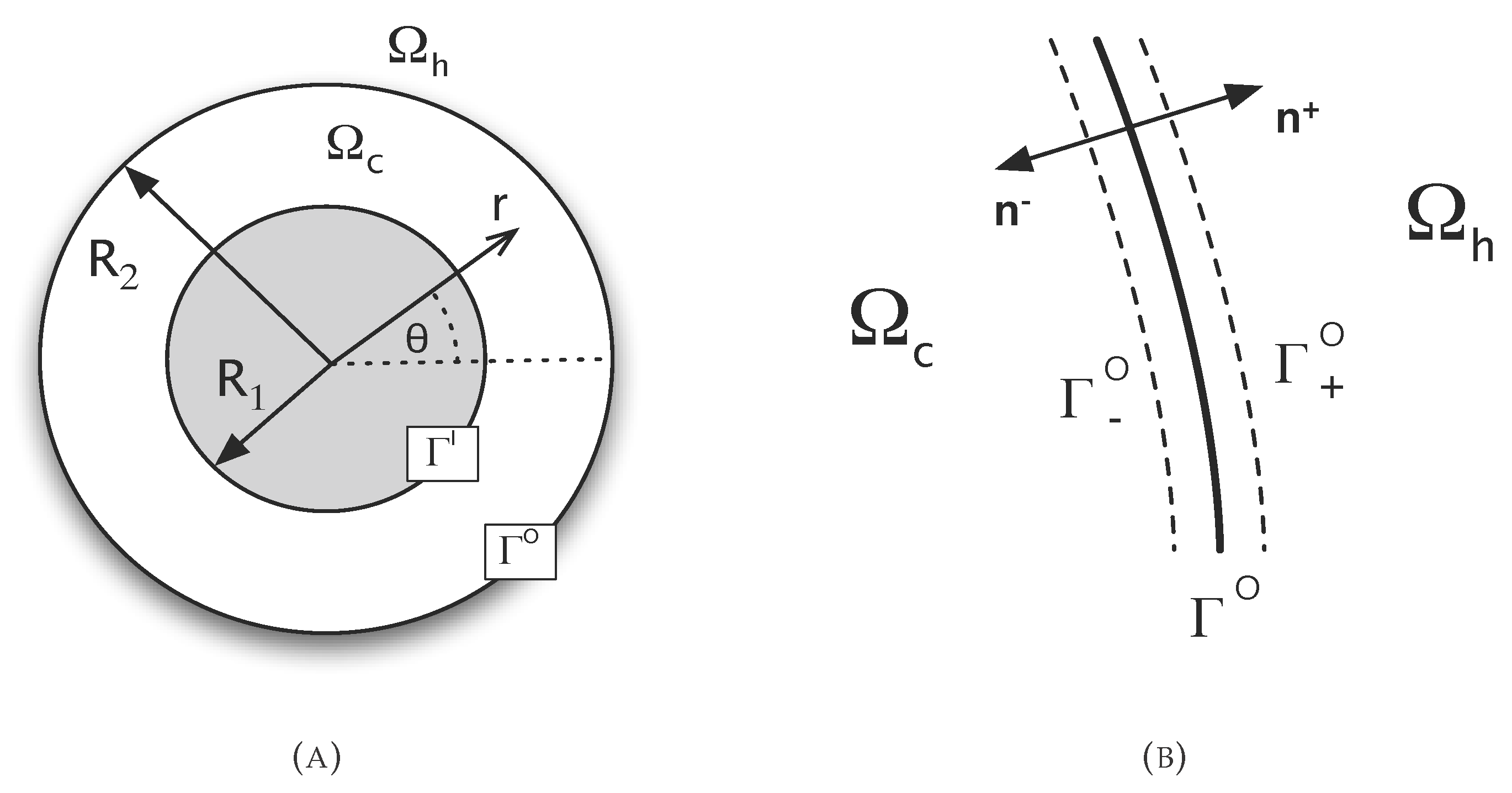
2. Integral Formulation of the Problem

Consider a sound-hard object impinged by an incoming acoustic perturbation. The acoustic field resulting from the superposition of the incoming wave, the primary or incident field and the scattered or secondary field, can freely propagate in the unbounded domain Ω. The latter is divided into two sub-domains, Ω h and Ω c . The first is occupied by a compressible medium with reference density ϱ 0 , bulk modulus B 0 and speed of sound c 0 = B 0 / ϱ 0 . The domain Ω c is occupied by a metamaterial capable of substantial modifications of the wave propagation pattern, so as to make the presence of the obstacle undetectable in Ω h .
In the present work, without loss of generality for the theoretical and numerical formulation, we limit our attention to the bi-dimensional problem depicted in Figure 1, for which an analytical solution of the cloaking problem exists and represents a standard benchmark (see Cummer and Shurig [4]). The approach used to recast the governing equations in an integral form is derived from Iemma and Burghignoli [16] and extended to moving obstacles in the presence of co-moving sound sources at a close distance. This extension represents the main novelty of the present work, the existing literature on the subject being limited to the analysis of a cloaked obstacle in the far field, assuming incoming planar wave fronts.
The standard coordinate transformation approach starts from the assumption that the physical domain Ω c can be obtained by transforming an obstacle-free virtual domain Ω ¯ through a mapping x = f ( x ¯ ) , x ¯ Ω ¯ . The transformation is invertible almost everywhere, all of the points being mapped one-to-one, with the exception of the reference point in Ω ¯ , which is mapped onto the boundary of the obstacle Γ I (see Figure 1 and Figure 2). In the following, the formalism adopted is that used in Norris [9]. Indicating with the bar differentiation with respect to x ¯ , the deformation tensor associated with the transformation is D = ¯ f ( x ¯ ) = ¯ x (with D i j = x i / x ¯ j ), and its Jacobian is J = det D . The Laplace operators in Ω ¯ and in Ω are related by the equation ¯ 2 = J · J - 1 V 2 where V 2 = D D T (clearly, D T = ¯ ; see Norris [9]). The core of the Standard Transformation Acoustic (STA) is in the interpretation of the coefficients arising from the coordinate transformation as the mechanical properties of a virtual material having unconventional properties. Defining B : = J and ϱ : = J V - 2 , the wave equation in Ω ¯ is transformed into:
B · ϱ - 1 p - p ¨ = 0 , x Ω c
This equation governs the propagation of an acoustic perturbation within a medium having anisotropic inertia, represented by the tensor ϱ and bulk modulus B . These unconventional mechanical properties cause an acoustic wave traveling in Ω c to be bent around the object and perfectly re-aligned behind it, exactly in the same fashion as straight lines in Ω ¯ c are bent by f ( x ¯ ) . An observer in Ω h sees undisturbed wave paths, thus achieving the desired cloaking effect. The actual manufacturing of metamaterials reproducing this unconventional behavior is currently one of the most intriguing technology challenges. Remarkable results have been obtained so far in the design of metamaterials mimicking this response, including the realization of experiments in the case of a medium and obstacle at rest (see, e.g., [10,17,18,19]).
The derivation of integral formulations for inhomogeneous wave operators formally identical to Equation (1) is not new. The formulation presented here extends to moving bodies and sources the approach introduced in Iemma and Burghignoli [16], which is closely related to the work presented in Martin [20]. It is worth mentioning also the early work of Stevenson [21] where the tailored Green’s function of Equation (1) is derived in the free-space and in a layered half-space. The improvement of the method presented in Iemma and Burghignoli [16] using Stevenson’s approach is currently under development. Assuming p ( x , t ) = p ˜ ( x ) e j ω t , Equation (1) is rewritten in the form of a non-homogeneous Helmholtz equation as:
2 p ˜ + k 0 2 p ˜ = · I - ϱ ^ - 1 p ˜ - ω 2 ϱ 0 1 B - 1 B 0 p ˜ , x Ω c
where I is the second-order identity tensor, ϱ ^ = ϱ / ϱ 0 . The acoustic analogy defined with Equation (2) simulates the inertial and elastic response of the cloaking layer as a distribution of field sources forcing the hosting medium in Ω c . Using this approach, an integral formulation of the problem can be easily obtained with the standard procedure (see, e.g., [16]) as:
E c ( y ) p ˜ ( y ) = Γ c G ( x , y ) p ˜ ( x ) n - p ˜ ( x ) G ( x , y ) n d Γ ( x ) + Ω c G ( x , y ) ζ ( x ) d Ω ( x ) , y Ω ¯ c
where Γ c Ω c = Γ I Γ - O is the boundary of the cloak, ζ ( x ) = · I - ϱ ^ - 1 p ˜ - p ˜ ω 2 ϱ 0 ( B 0 - B ) / B B 0 and G ( x , y ) is the free-space Green’s function. In Equation (3), the effect of the metamaterial is accounted for as a single monopole source, yielding to a relatively simple numerical implementation, at the cost of the evaluation of the divergence of q = I - ϱ ^ - 1 p ˜ . This approach has been widely assessed for the static case in Iemma and Burghignoli [16]. In the present work, a second formulation is introduced, in order to avoid the numerical evaluation of the divergence in ζ:
E c ( y ) p ˜ ( y ) = Γ c G ( x , y ) p ˜ ( x ) n - p ˜ ( x ) G ( x , y ) n d Γ ( x ) + Ω c G ( x , y ) · q ( x ) d Ω ( x ) + Ω c G ( x , y ) σ ( x ) d Ω ( x ) , y Ω ¯ c
In this second formulation, the metamaterial contributes with the sum of a monopole proportional to σ = p ˜ ω 2 ϱ 0 ( B - B 0 ) / B B 0 and a dipole defined by · q . Integrating by parts the first volume integral and applying the Gauss theorem (recalling the orientation of Γ) yields:
E c ( y ) p ˜ ( y ) = Γ c G ( x , y ) p ˜ ( x ) n - q ( x ) · n - p ˜ ( x ) G ( x , y ) n d Γ ( x ) - Ω c q ( x ) · G ( x , y ) d Ω ( x ) + Ω c G ( x , y ) σ ( x ) d Ω ( x ) , y Ω ¯ c
where the evaluation of the second derivatives of p ˜ is avoided.
The derivation of an integral formulation valid in Ω h must take into account the motion of the object and the source. In a frame of reference R rigidly connected with the moving object, the propagation of an acoustic perturbation for the velocity potential function φ ( x , t ) is governed by the convective wave equation:
2 φ - 1 c 0 2 t - v b · 2 φ = 0 , x Ω h
Equation (6) simply states that an observer moving at speed v b sees the acoustic perturbations in Ω h as propagating in a fluid moving as a uniform stream with velocity v 0 = - v b . It is important to notice that Equation (6) does not take into account the aerodynamic perturbation velocity induced in the surrounding medium by the motion of the obstacle, nor its modification due to the presence of the cloaking layer. This limitation necessarily yields an unphysical matching condition at the outer interface. This will result in an imperfect cloaking of the object even in the presence of the convective metamaterial design (see Section 5). On the other hand, Huang et al. [14] shows that the use of a convective cloak design produces an improvement of the masking capability even if the simplistic assumption of a uniform stream is used (see Figure 1 of [14]) and that the introduction of a more realistic external flow pattern recovers the complete cloaking property of the metamaterial layer. As already mentioned, one of the objectives of the present paper is the development and the preliminary validation of an efficient numerical solution of the aeroacoustic cloaking based on the integral formulation of the problem, and for this reason, the analysis is limited to the uniform stream assumption.
The reformulation of the convective wave equation into a boundary integral equation can be considered as a standard procedure in aeroacoustics and potential aerodynamics, and the literature available on the subject is extensive. Formulations close to the one presented here can be found in Morino et al. [22], Guo [23] and Agarwal and Morris [24]. Defining the Mach number of the relative uniform flow, M 0 , the integral formulation in the frequency domain of the above equation can be easily obtained as:
E c ( y ) φ ˜ ( y ) = Γ E G ^ ( x , y ) φ ˜ ( x ) n - M 0 n M 0 · φ ˜ ( x ) d Γ ( x ) + Γ E φ ˜ ( x ) 2 i k 0 M 0 n G ^ ( x , y ) + M 0 n M 0 · G ^ ( x , y ) - G ^ ( x , y ) n d Γ ( x ) , y Ω ¯ h
where M 0 n = M 0 · n and G ^ ( x , y ) is the free-space solution of 2 G ^ + j k 0 2 + M 0 · 2 G ^ = δ ( x - y ) . It important to notice that the integrals in Equation (7) extend on Γ E Γ + O , i.e., on the outer side of the interface between the two media. This point is important in the derivation of the continuity conditions that will be used to couple Equations (3) and (4) with Equation (7).

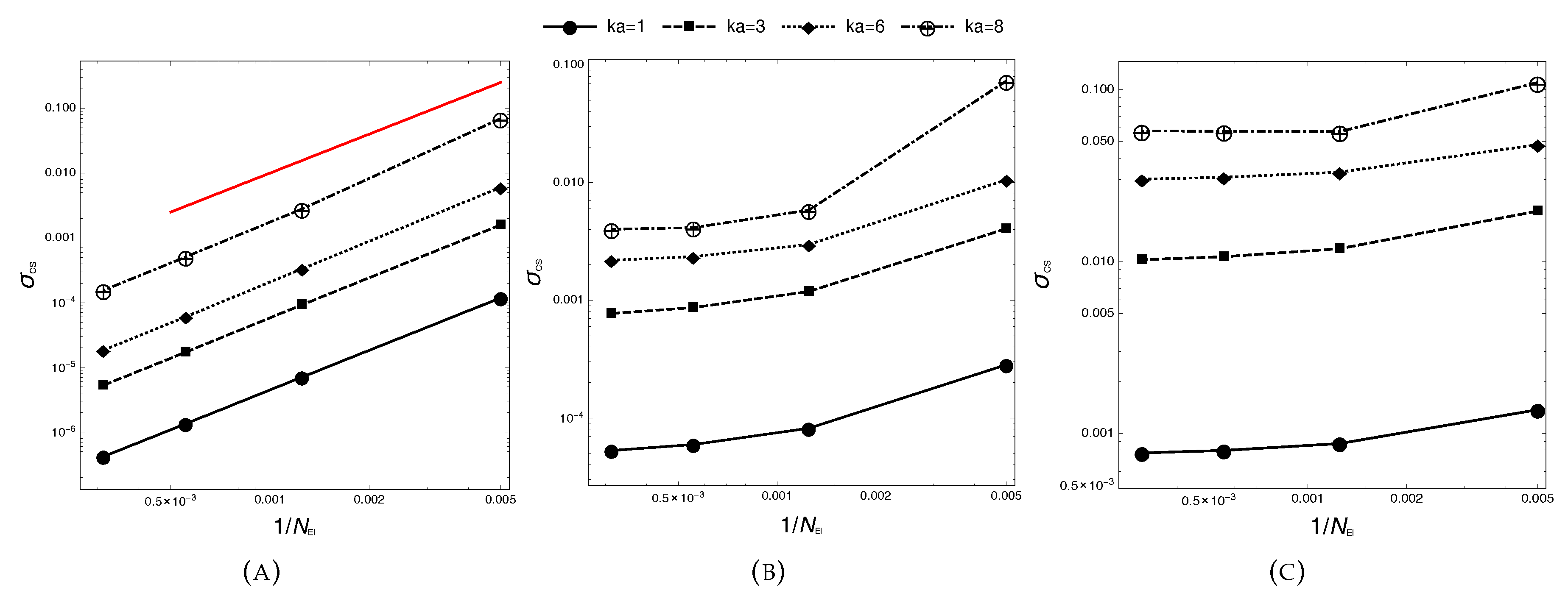
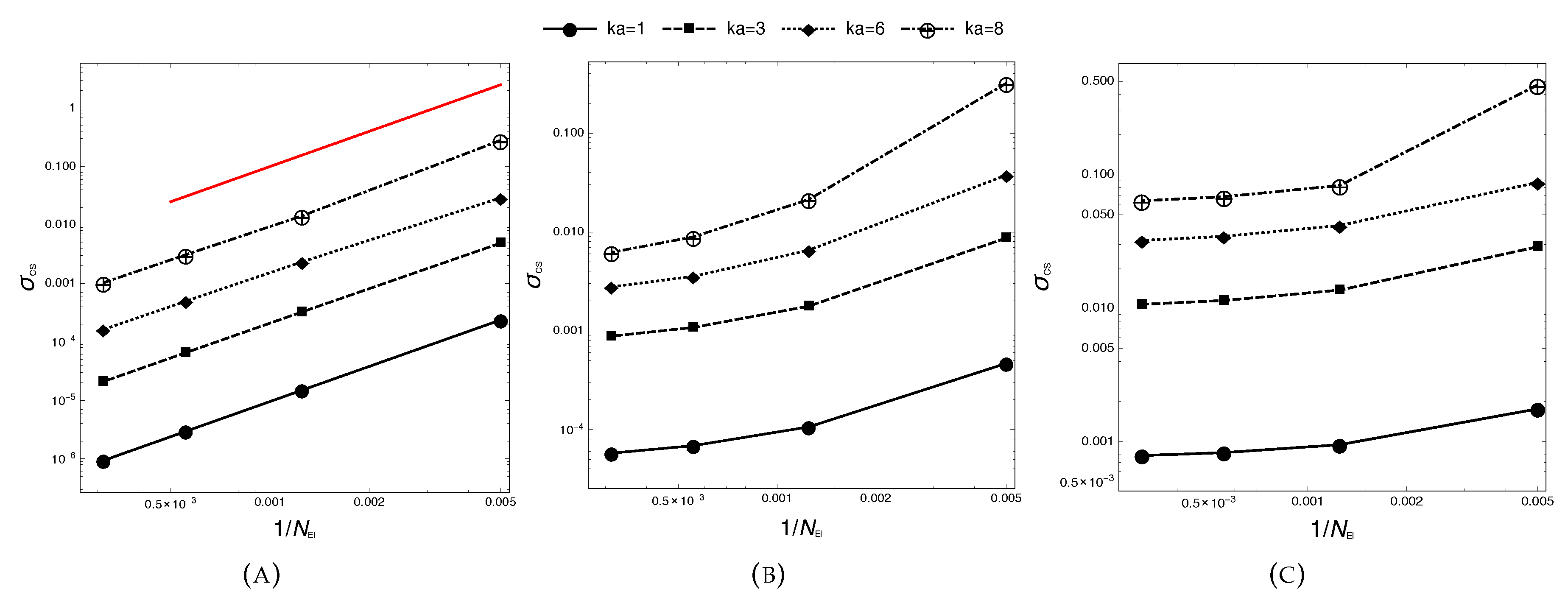
3. Numerical Solution

Equations (3) and (4) in Ω c and Equation (7) in Ω h must be solved simultaneously to simulate properly the effect of the cloaking layer on the scattering in the host medium. In order to do this, it is important to derive suitable continuity conditions at the interface between the two media. Assuming as negligible the motion of the outer boundary Γ O induced by the acoustic perturbation, the continuity of the acoustic field is expressed in term of pressure and normal acceleration. The unit normals to the two sides of Γ O , Γ - O and Γ + O , are denoted by n - and n + , respectively with n + = - n - = n (see Figure 1). The boundaries of the two sub-domains are defined as Ω c = Γ I Γ - O , Ω h = Γ E . The boundary conditions on Γ I depend on the nature of the object. Here, we analyze the simple case of a sound-hard obstacle (see Iemma and Burghignoli [16] for general boundary conditions on Γ I ). The momentum conservation equations in the cloak and in the host are given by:
v t = - ϱ - 1 p for x Ω c , D v D t = - 1 ϱ 0 p for x Ω h
with D / D t = / t + v 0 · . Combining the above equations and deriving the relationship between pressure and velocity potential in Ω h by integrating the momentum equation under the assumption of homentropic, potential flow, the continuity of the acoustic field at the media interface in the frequency domain becomes:
p ˜ O n - = - ϱ r ϱ 0 p ˜ E n + , p ˜ O = - j ω φ ˜ E + v 0 · φ ˜ E , x Γ O
where the tensor ϱ has been assumed to be diagonal with [ ϱ ] 11 = ϱ r (see Norris [9] and Iemma and Burghignoli [16] for details) and the superscripts O and E denote the solutions of Equation (2) in Ω c and Equation (6) in Ω h , respectively.
The numerical solution of the problem is obtained using the extended boundary element method presented in Iemma and Burghignoli [16], suitably adapted to take into account the field terms appearing in Equations (3) and (4). Each boundary contour is divided into M line elements, and the domain Ω c is partitioned into N quadrilateral elements. The variables are assumed to be piece-wise constant on each element, and the collocation method is used to solve the problem, with collocation points located at the centers of the elements. The column vectors collecting the value of the pressure and its normal derivatives are indicated with as p ˜ X and χ ˜ X , where the superscript X is equal to I , O , or Ω, to indicate collocation on Γ I , Γ O , or in Ω c , respectively. The vectors collecting the values of velocity potential and its normal derivatives on Γ E are indicated with φ ˜ E and ψ ˜ h . In a similar fashion, the single and double layers’ integral coefficients arising from the discretization of the equations are assembled into matrices denoted with B XY and C XY , respectively, whereas the field source and dipole coefficients are collected into matrices H XY , G r XY and G θ XY (see Appendix for the definition of each coefficient). In the matrices’ naming scheme, the first superscript indicates the sub-domain where y is located and the second one that to which the influencing element belongs. Finally, D r , D θ and S are the finite-difference operators that build q and ζ from the pressure. Assuming a sound-hard object, Equation (3) yields a final system of equations having the form:
Y II p ˜ I + B IO χ ˜ O + C IO p ˜ O - H I Ω S p ˜ Ω = 0 C OI p ˜ I + B OO χ ˜ O + Y OO p ˜ O - H O Ω S p ˜ Ω = 0 C Ω I p ˜ I + B Ω I χ ˜ O + C Ω O p ˜ O + I - H Ω Ω S p ˜ Ω = 0
with Y XY = 0 . 5 I + C XY , whereas for Equation (5), we obtain:
Y II p ˜ I + B IO Q O χ ˜ O + C IO p ˜ O + G r I Ω Q r Ω D r + G θ I Ω Q θ Ω D θ - H I Ω p ˜ Ω = 0 C OI p ˜ I + B OO Q O χ ˜ O + Y OO p ˜ O + G r O Ω Q r Ω D r + G θ O Ω Q θ Ω D θ - H O Ω p ˜ Ω = 0 C Ω I p ˜ I + B Ω I Q O χ ˜ O + C Ω O p ˜ O + I + G r Ω Ω Q r Ω D r + G θ Ω Ω Q θ Ω D θ - H Ω Ω p ˜ Ω = 0
The Q matrices contain the inertial coefficients of the radial and azimuthal components of the vector q on Γ O and in Ω c . In order to couple the above system of equations with the acoustic field in Ω h , the acoustic perturbation is assumed to be the superposition of a primary (or incident) field, p ˜ p , φ ˜ p , i.e., the field that would be present in Ω if all of the obstacles were absent, and the secondary (or scattered) field, p ˜ s , φ ˜ s , induced by the presence of the scattering objects. Applying the same discretisation procedure and taking into account the fact that the primary field satisfies Equation (7) yields:
ψ ˜ s E = B ^ EE - 1 1 2 I + C ^ EE φ ˜ s E = Z ^ EE φ ˜ s E
Equation (12), together with Equation (9), is used to rewrite the systems eliminating the terms χ ˜ O from the unknowns. Denoting the column vectors of unknown and known terms as:
z = p ˜ I φ ˜ s E p ˜ Ω , b = ψ ˜ p E φ ˜ p E
The linear system of 2 M + N equations in 2 M + N unknowns can be written as:
z = A ϱ , K , k 0 ) K ( ϱ ^ , k 0 b
where the dependence of the system matrices on the cloak’s parameter has been explicitly introduced. Regardless of the formulation used, matrix K has the form:
K = - ϱ ^ B IO B - C IO - ϱ ^ B OO B - Y OO - ϱ ^ B Ω I B - C Ω O
where ϱ ^ = ϱ 0 / ϱ r and B is the discrete Bernoulli’s operator, relating pressure and velocity potential on Γ E . On the contrary, matrix A depends on the formulation used. Specifically, Equation (3) yields:
A = Y II C IO - ϱ ^ B IO B Z ^ EE - H I Ω S C OI Y OO - ϱ ^ B OO B Z ^ EE - H O Ω S C Ω I C Ω O - ϱ ^ B Ω I B Z ^ EE I - H Ω Ω S - 1
whereas Equation (5) produces:
A = Y II C IO - ϱ ^ B IO B Z ^ EE G r I Ω Q r Ω D r + G θ I Ω Q θ Ω D θ - H I Ω C OI Y OO - ϱ ^ B OO B Z ^ EE G r O Ω Q r Ω D r + G θ O Ω Q θ Ω D θ - H O Ω C Ω I C Ω O - ϱ ^ B Ω I B Z ^ EE I + G r Ω Ω Q r Ω D r + G θ Ω Ω Q θ Ω D θ - H Ω Ω - 1
The matrix T ( ϱ , K , k 0 ) = A ϱ , K , k 0 ) K ( ϱ ^ , k 0 can be considered as the matrix transfer function of the cloaked object relating the incident field on Γ E (which is known) with the solution in Ω ¯ c . Once that the solution z is known, the velocity potential field in Ω h can be obtained as φ ˜ s h = B ^ EE ψ ˜ s E - C ^ EE φ ˜ s E .

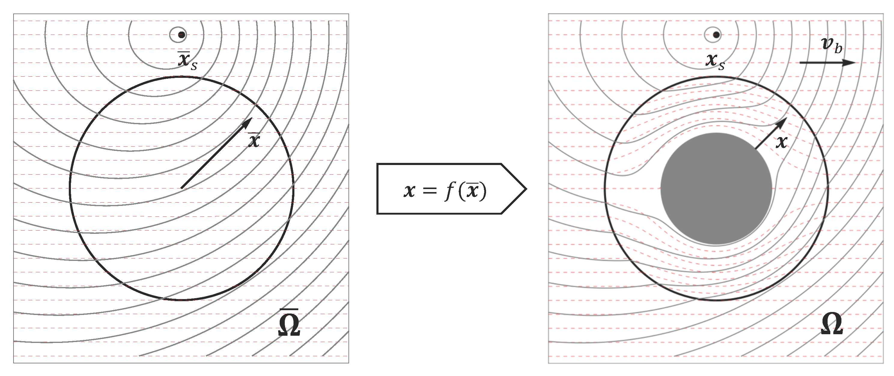
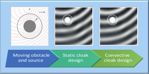
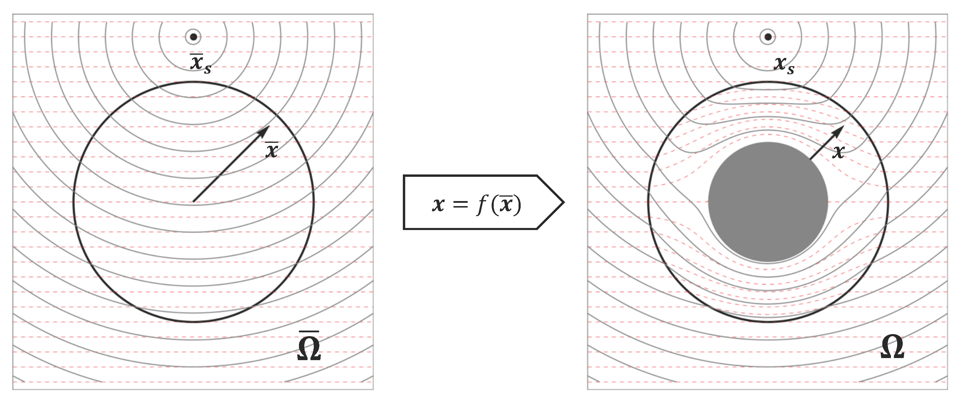
4. Effect of Motion on the Metamaterial Design

In the model developed so far, the mechanical properties of the cloaking layer are obtained by applying the coordinate transformation to the Helmholtz equation in the virtual domain Ω ¯ . The definition of ϱ and B does not take into account the effect of the relative motion of the cloaked object and the hosting medium. As already mentioned in the Introduction, the problem has been already addressed in the literature by several authors. In particular, Huang et al. [14,15] have developed an approach that is, in the author’s opinion, the most suitable for a direct application to real aeroacoustic problems. In particular, in [14], the convective design of the cloaking material is obtained by imposing the matching of the wave vector at the cloak/host interface, taking into account the effect of a uniform mean flow in Ω h on the propagation speed of an incoming plane wave. Equivalent source terms are then derived using the first Born approximation. The use of this approximation is definitely legitimate in the specific application addressed in that paper, since the static cloak, used as a reference design, guarantees by itself a negligible scattering field. In general, when the mechanical properties of the cloaking layer are not known a priori and no reasonable initial guesses can be made, a simulation based on Born approximation could lead to inconsistent results. Let us consider, for example, the numerical optimization of the metamaterial properties starting from scratch. The optimization procedure could, in principle, explore regions of the design space leading to a very poor cloaking performance. The use of the Born approximation for the simulation of these design points could drive the optimization scheme towards the wrong optimization dynamics.
The integral formulation proposed here is derived without making a priori assumptions on the intensity of the scattered field, thus being suitable to analyze coherently any scattering problem. Furthermore, the objective of the present research makes the assumption of incoming plane waves not acceptable.
An observer co-moving with the frame of reference R , rigidly connected with the object and source (i.e., the frame of reference used so far in the development of the formulation) sees an acoustic field proportional to exp j ω c t - k 0 · x , where ω c is the observed angular frequency and x is the position vector in R . Indicating with X the position vector in a frame of reference at rest, R, the coordinate transformation between R and R reads X = x - v b t . Using this transformation and imposing the frame invariance of the local wave structure, we obtain the classic Doppler correction for the frequency observed in R :
ω c = ω 1 - k ^ 0 x · M b
where k ^ 0 is the local unit wave vector, not constant in space for a moving source close to the observation point (see Figure 3). Using an approach similar to Huang et al. [14], we obtain the convective correction of the metamaterial properties as:
ϱ M ( x ) = ϱ ( x ) 1 - k ^ 0 x · M b , B M ( x ) = B ( x ) 1 - k ^ 0 x · M b
In case of planar wave fronts, and considering that the convective Mach observed in R is M 0 = - M b , the correction indicated by Equation (19) reduces to Equation 11 of [14]. It is important to notice that the use of this correction in the present formulation is extremely simple. Indeed, Equation (20) simply changes into:
2 p ˜ + k 0 2 p ˜ = · I - ϱ ^ M - 1 p ˜ - ω 2 ϱ 0 1 B M - 1 B 0 p ˜ , x Ω c
In addition, the use of Equation (5) avoids the evaluation of the derivatives of the correction factor yielding a corrected integral formulation in Ω c having the form:
E c ( y ) p ˜ ( y ) = Γ c G ( x , y ) p ˜ ( x ) n - q M ( x ) · n - p ˜ ( x ) G ( x , y ) n d Γ ( x ) - Ω c q M ( x ) · G ( x , y ) d Ω ( x ) + Ω c G ( x , y ) σ M ( x ) d Ω ( x ) , y Ω ¯ c
It must be pointed out that the correction factor so obtained is not constant in space and depends on the source location, resulting, in principle, in a more complex practical realization of the device. Nevertheless, this difficulty is not critical in those applications where the relative position of scatterers and sources is known and invariant.

5. Results and Discussion

Equation (3) presented in Section 2 has been extensively validated in Iemma and Burghignoli [16] on the classic test case of a circular cylinder subject to an impinging plane wave, using the cloak design first introduced by Pendry et al. [2] for the electromagnetic fields and ported to acoustics by Cummer and Shurig [4]. Here, we use the same benchmark to assess Equations (3) and (5) in the case of a moving cylinder impinged by the field induced by a co-moving monopole point source located at x s = ( 0 , 5 R 2 ) . In polar coordinates, ( r , θ ) , the static cloak design is given by:
ϱ ^ = r r - R 1 0 0 r - R 1 r , B = B 0 R 2 - R 1 R 2 2 [ ϱ ^ ] 11
The validation of the method starts with the analysis of the h-convergence of the numerical scheme. The parameter adopted to measure the cloaking efficiency is the scattering cross-section, here defined as:
σ c s = 1 2 π 0 2 π p ˜ s rms p ˜ p rms 2 , d θ = 1 2 π 0 2 π | p ˜ s | 2 | p ˜ p | 2 d θ
The domain Ω c is partitioned into 200 N e l 3200 field elements, and the analysis is performed in the reduced frequency range 1 k a 8 , with a = R 2 . The static cloak design is used for Mach numbers in the range 0 . 0 M b 0 . 2 .
The numerical results are presented in Figure 4 and Figure 5. In case of an object and source at rest ( M b = 0 . 0 ), both formulations appear to converge with a rate O ( h 2 ) , as the comparison with the reference red line in the log-log plots confirms. As expected, the absolute value of σ c s for a specific value of N e l is lower at lower frequencies, because of the higher number of elements per wavelength. For increasing the Mach number, the cloaking efficiency deteriorates significantly, both in terms of the rate of convergence and the value of the scattering cross-section. Furthermore, this result is not surprising, since the metamaterial used in these tests is based on the static design, Equation (22), which is not capable of completely adjusting the local impedance of the cloaking layer in the presence of the background convection in Ω h . The effect of the reduced efficiency of the cloak at higher Mach numbers can be clearly seen in Figure 6, where the density plot of the pressure field in Ω c Ω h is presented for both formulations at M b = 0 . 0 and M b = 0 . 1 . The primary field in the hosting medium appears almost undisturbed in the case of an object at rest, whereas significant perturbations are present when M b = 0 . 1 .

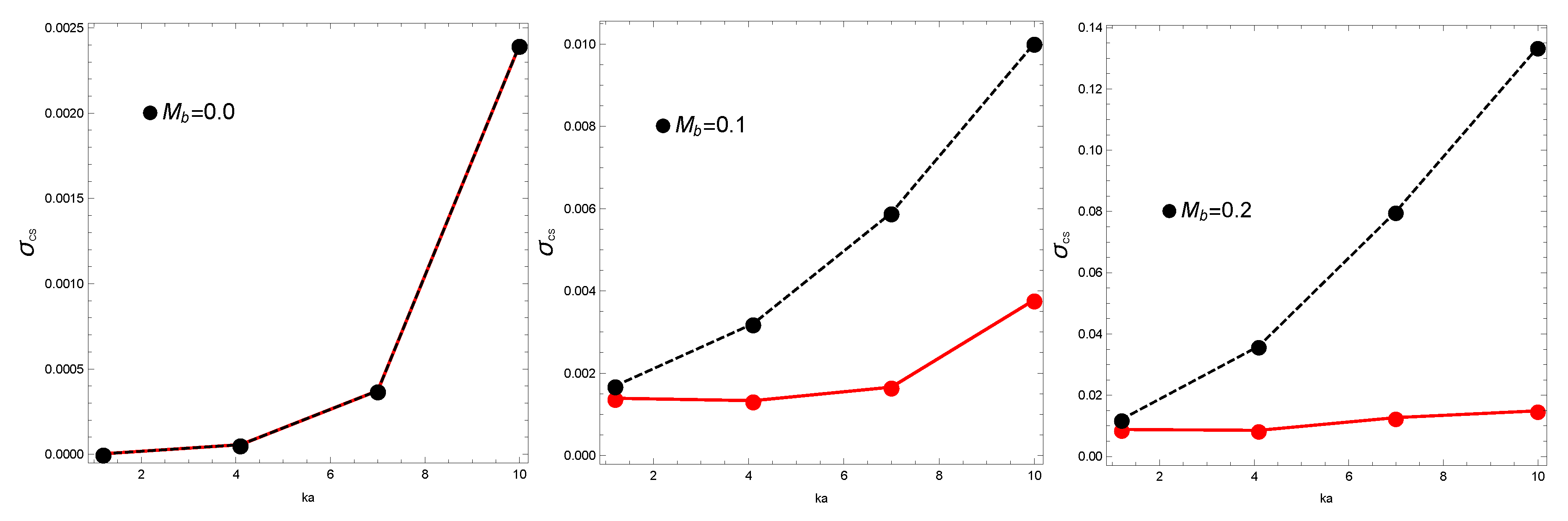
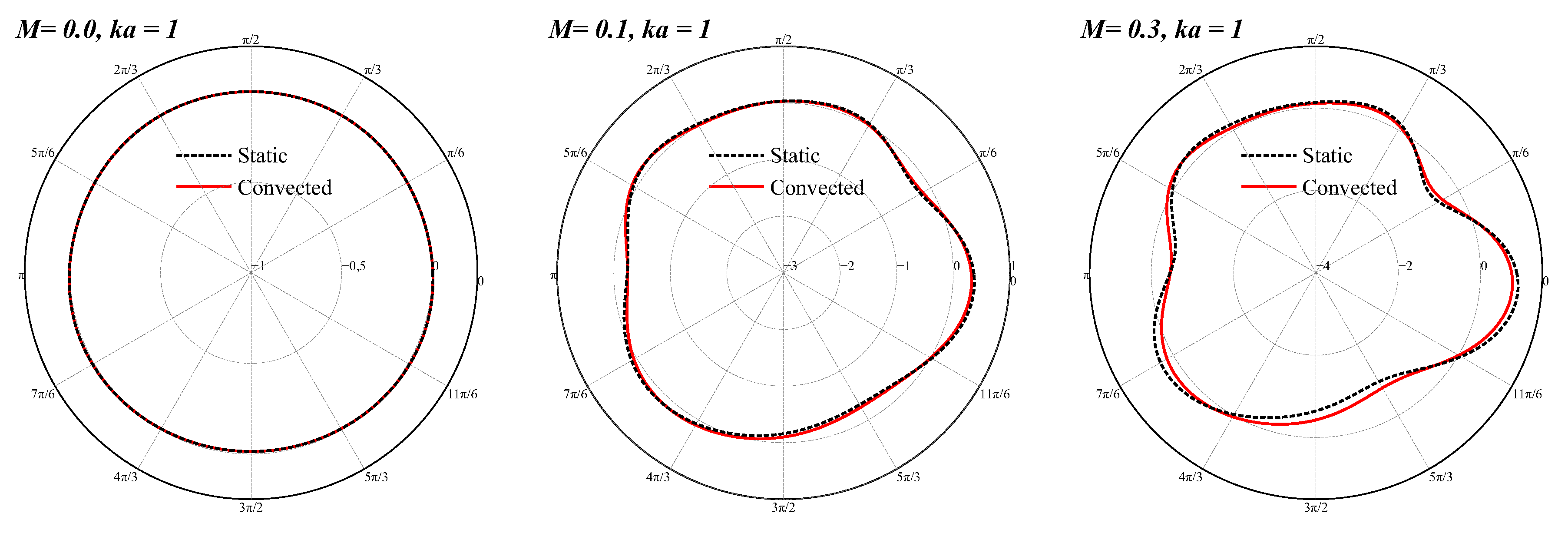
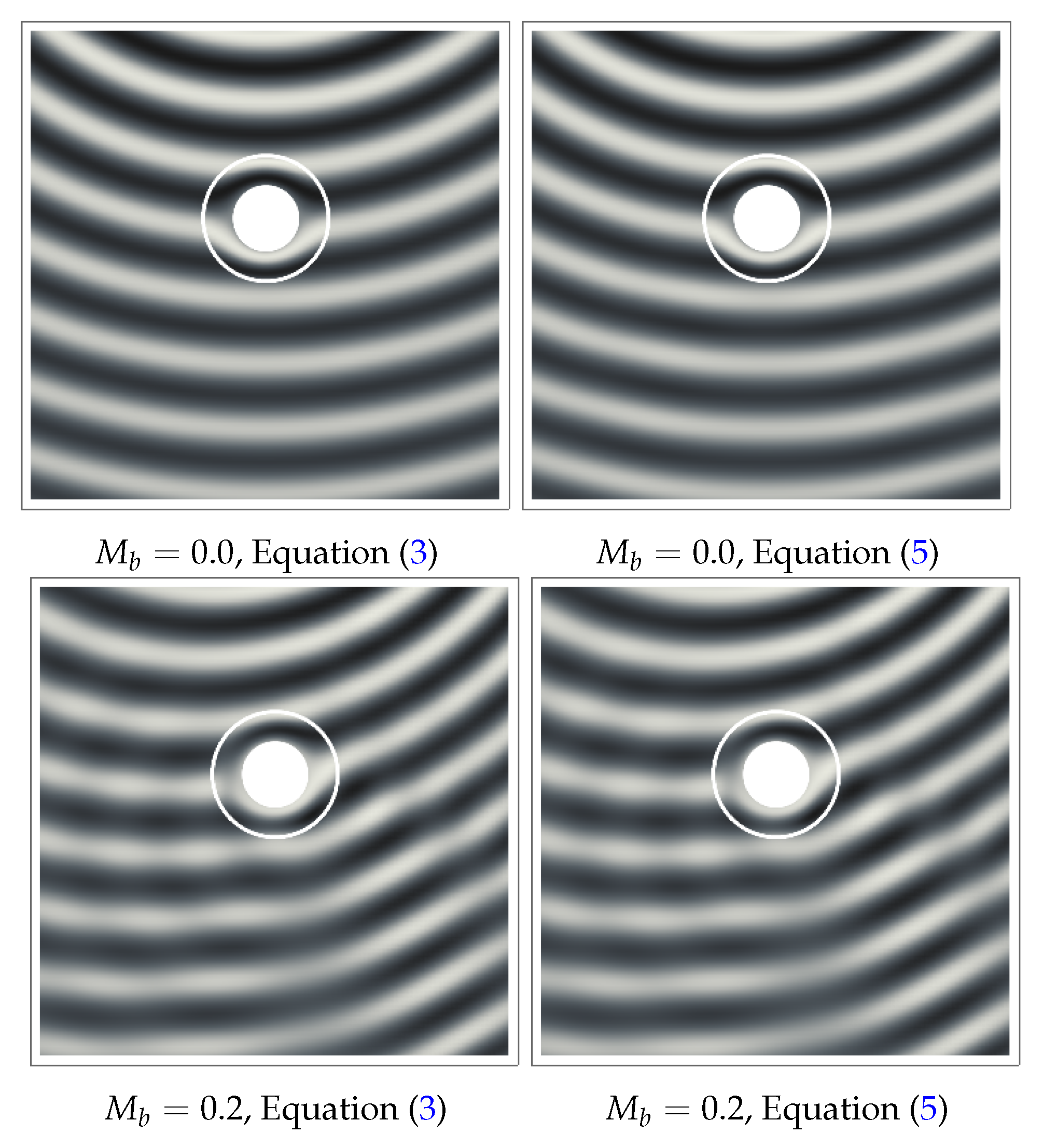
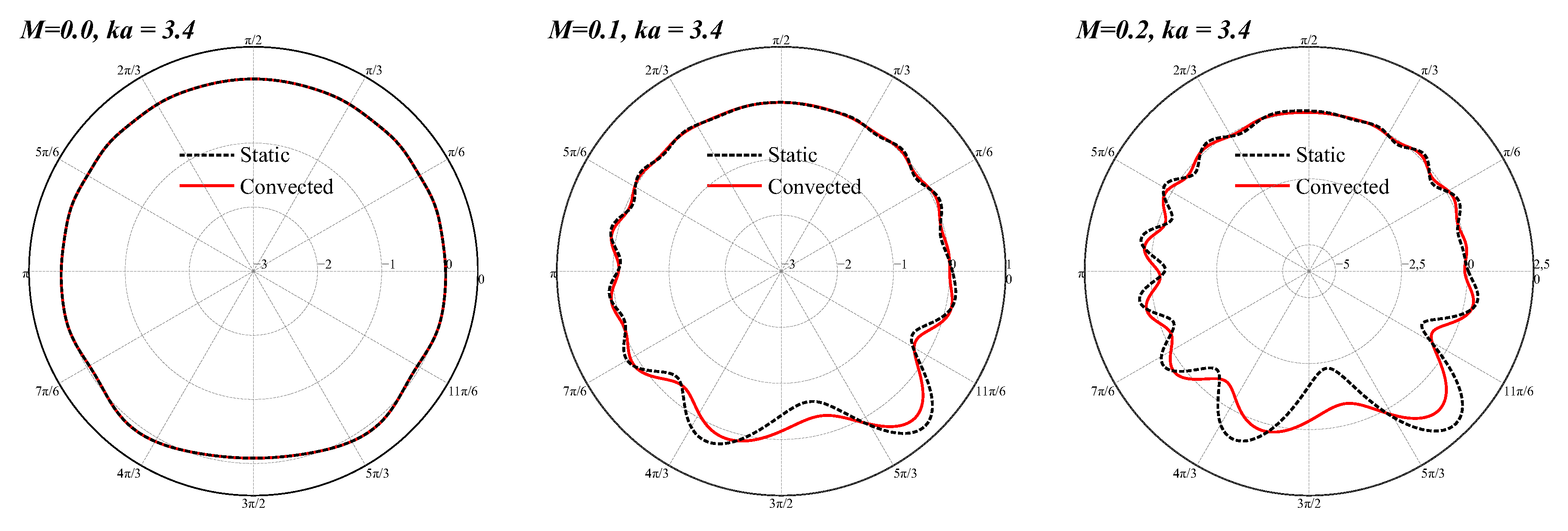
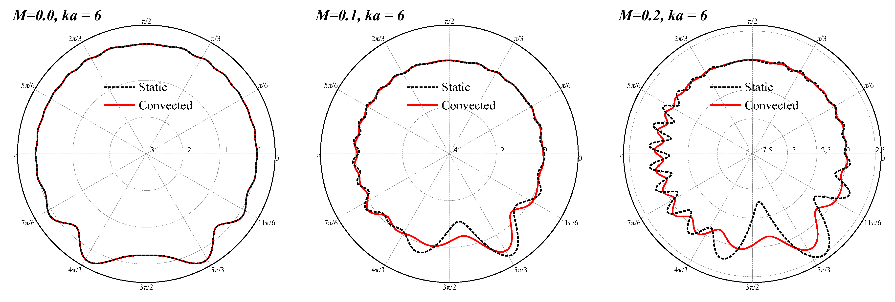
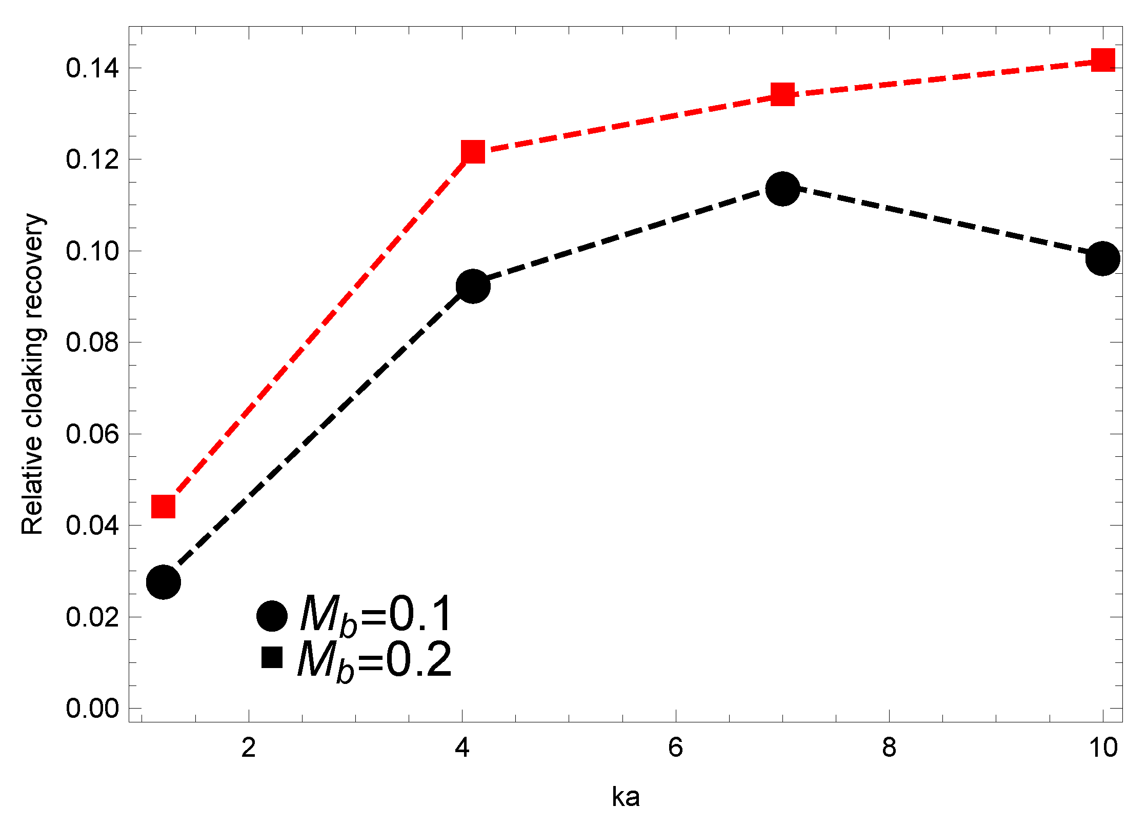
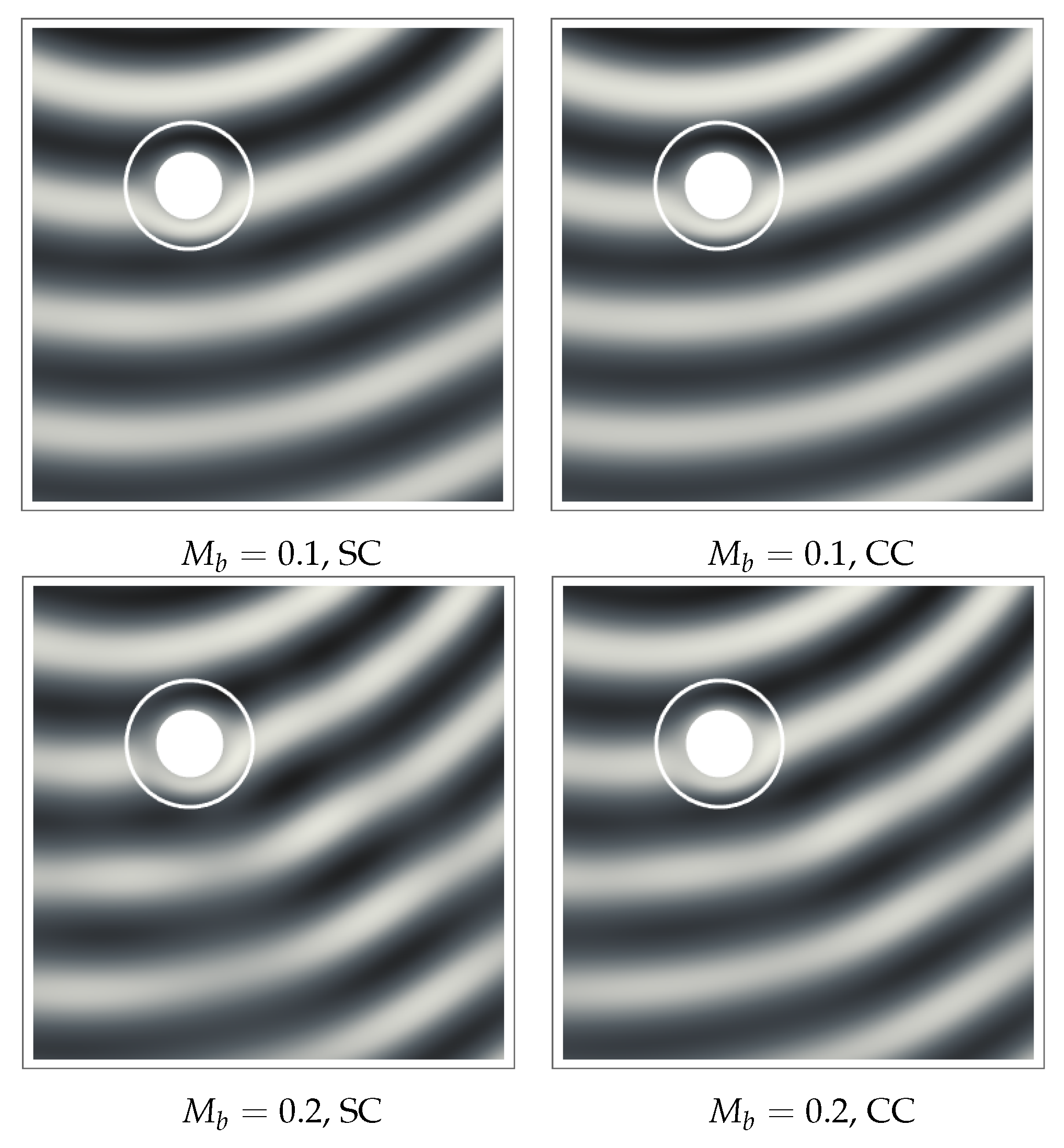
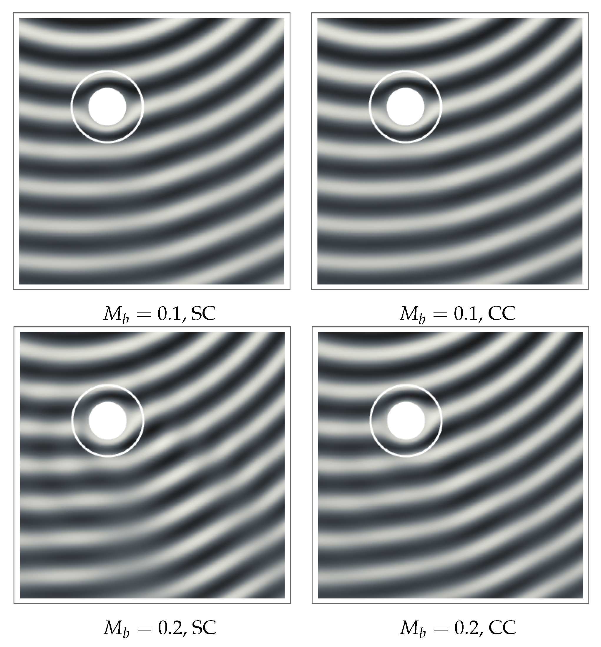
5.1. Effect of Convective Cloak

The efficiency loss observed in the presence of motion can be substantially reduced using the corrected cloak design presented in Section 4. The effect of the local Doppler correction on the scattering cross-section σ c s is presented in Figure 7. As anticipated in Section 4, the corrected cloak design is applied only to Equation (5) to avoid the numerical evaluation of the derivatives of the correction factor in the divergence of ζ.
The beneficial influence of the correction is evident, resulting in a maximum abatement of the scattering signature of more than one order of magnitude for the object in faster motion and at higher frequencies. Additional information about the behavior of the convective cloaking layer can be achieved by observing the polar pattern of the insertion loss, calculated as:
I L = 20 log 10 | p ˜ s | 2 | p ˜ p | 2
Figure 8 depicts the directivity patterns measured at r = 20 R 1 , for k a = 1 and three values of M b . At low frequency, the red curves, the solution of Equation (21), are slightly closer to the perfect cloak limit ( I L = 0 ) along the entire evaluation contour than those obtained with Equation (5). The beneficial effect of the correction is much more evident at higher frequencies (Figure 9 and Figure 10), as to be expected from the analysis of σ c s presented in Figure 7.
This result is confirmed by Figure 11, where the relative cloaking performance recovery is shown. The performance recovery is defined as | σ c s S C - σ c s C C | / | σ c s S C | , where superscripts S C and C C indicate the static and convective cloak design, respectively.
The masking recovery clearly appears to increase with Mach number and reduced frequency, at least in the range analyzed. The visual sketch of the wave patterns in Ω c Ω h is presented in Figure 12 for k a = 3 . 4 and Figure 13 for k a = 6 . The use of the convective cloak design reduces substantially the perturbation of the wave fronts due to the residual scattering, recovering almost completely the wave pattern of the primary field induced by the moving source.

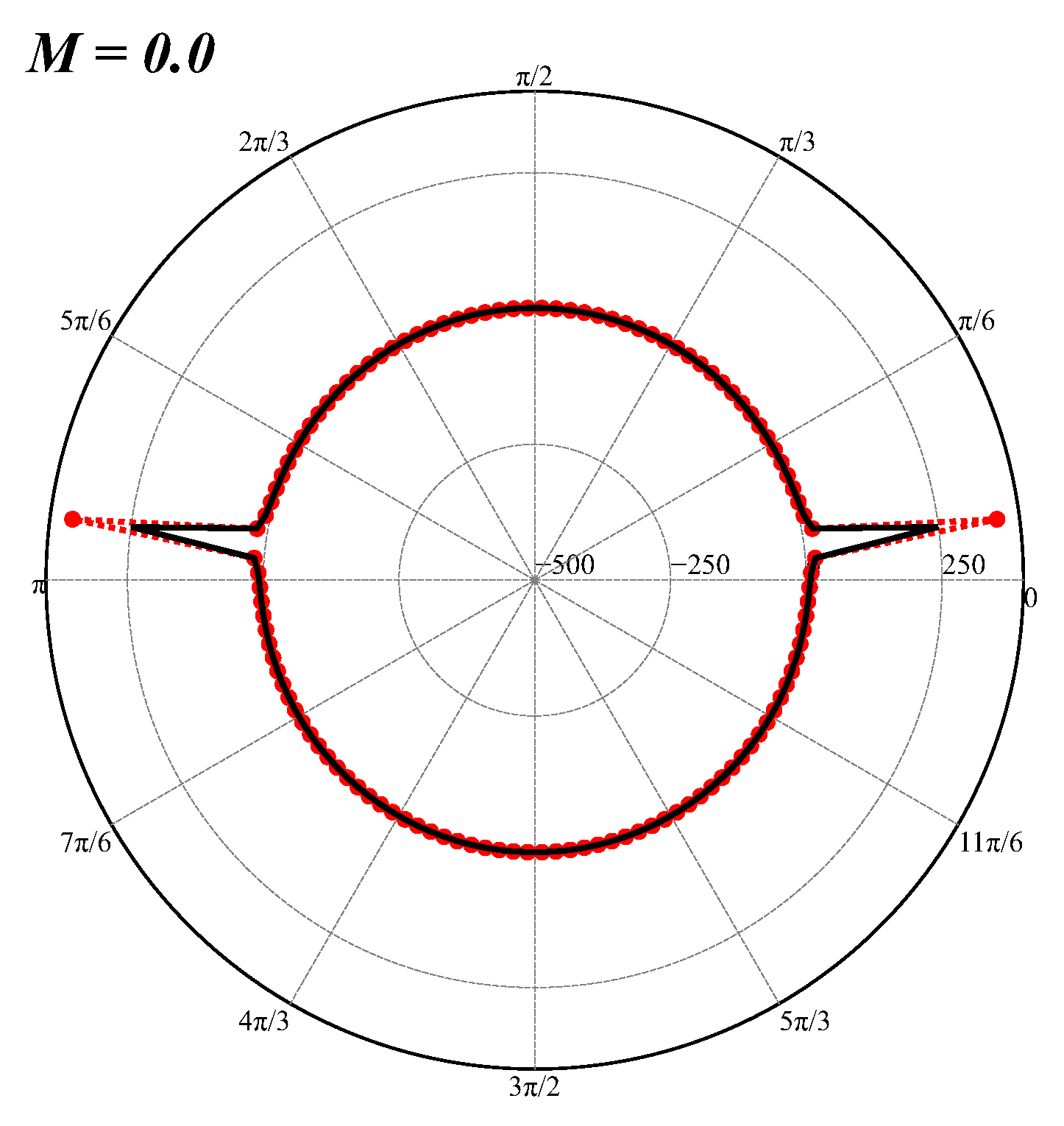
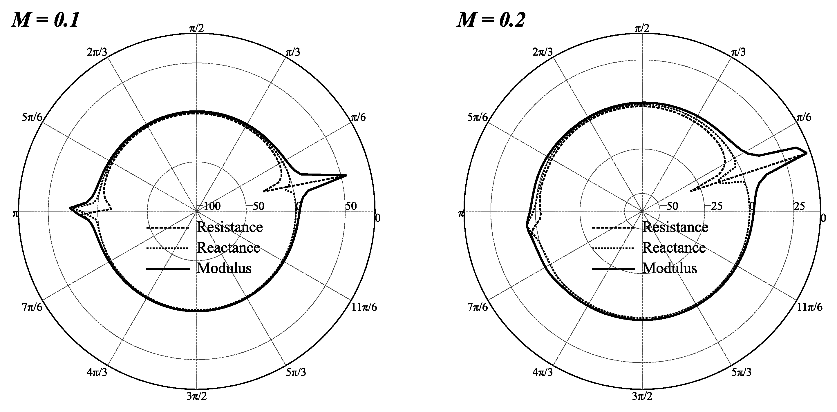
5.2. Boundary Impedance Estimate

This section is dedicated to the re-interpretation of the results obtained in terms of an equivalent wall impedance distribution on Γ O . Indeed, the availability of a reliable end efficient tool for the modeling and simulation of metamaterials in aeroacoustics could be, in principle, considered as an alternative approach to the non-trivial task of identifying the optimal distribution of surface impedance required to attain a specific acoustic response. In aeronautics, this possibility would represent a major improvement in the design of specific passive noise-controlling devices, such as nacelle liners and high-lift device surface treatments. Indeed, the estimate of the wall impedance in the presence of flow is not a trivial task (see, e.g., [25,26,27]). The numerical simulations required are extremely time consuming (and often not completely reliable), and experiments are extremely expensive. Consequently, the design of noise abatement devices is a design task that absorbs a large amount of resources, especially in the presence of environmental constraints becoming stricter and stricter. In this preliminary work, we address the problem simply by assuming that the outer boundary of the cloak is a locally-reactive surface and evaluating the local impedance Z = R + j X . It is important to stress the fact that we are not claiming that the metamaterial could act as a locally-reacting surface. It is simply a re-thinking of the problem to guess what kind of locally-reacting surface treatment could mimic the behavior of our cloaking device. The rationale behind this stems from the consideration that the aeronautical industries have developed advanced technical capabilities in the realization of active and passive surface treatments to attain specific impedance distributions, and in most cases, the major difficulties are in the identification of the impedance distribution required for a specific acoustic response. To this aim, the acoustic metamaterial theory could be interpreted as a tool to circumvent these difficulties. This evaluation of Z is simplified, in the present formulation, by the use of the velocity potential function φ ˜ as the unknown function in Ω h , the acoustic flow on Γ + O being directly obtainable from ψ ˜ s E + ψ ˜ p E . In a locally-reacting surface, the normal component of the particles’ acoustic velocity is proportional to the local value of the acoustic pressure through the complex value of the acoustic admittance, A = Z - 1 . For such a surface, acoustic invisibility can be achieved through the perfect matching of the local value of Z with the specific impedance of the medium, Z 0 = ϱ 0 c 0 . Indicating with α the angle between the local normal to the surface and wave vector of the impinging perturbation, the reflection coefficient is defined as (see, e.g., [28]):
R = Z sin ( π / 2 - α ) - ϱ 0 c 0 Z sin ( π / 2 - α ) + ϱ 0 c 0 = Z cos ( α ) - ϱ 0 c 0 Z cos ( α ) + ϱ 0 c 0
The invisibility condition can be derived analytically for simple sources in static conditions from Equation (25) as Z = ϱ 0 c 0 / cos α .
Figure 14 shows the results for the simple case of a monopole at rest. The polar distribution obtained at M b = 0 . 0 is compared to the theoretical value of Z required to guarantee the impedance matching with the free medium. The agreement with the theoretical prediction is remarkable. The azimuthal location of the impedance peaks (corresponding to an incoming local wave vector tangent to Γ E ) are perfectly captured, whereas their intensity is slightly underestimated, consistently with a substantially reduced, but not completely canceled, scattering field. Figure 15 shows the effect of the motion on the wall impedance polar distribution. The distortion of the azimuthal pattern induced by the motion of the obstacle and source is evident at M b = 0 . 1 and M b = 0 . 2 .

5.3. Computational Efficiency

One of the advantages of the formulation presented is the high computational efficiency with respect to other approaches based on finite volumes (FV), finite differences (FD) or finite elements (FE) methods. Although the present integral formulation requires the evaluation of field integrals, these are confined within the cloaking layer, and the overall computing effort remains remarkably low. In addition, the computational efficiency of the numerical scheme takes advantage of the high level of intrinsic parallelism typical of the collocation methods based on integral equations. Indeed, the set of integral coefficients pertaining to each collocation point can be calculated independently, and the matrices to be assembled are smaller (although denser) than those typical of FV, FD or FE methods. The method presented has been implemented by embedding adaptive numerical quadrature C-routines in a scalable parallel environment written in the Wolfram Mathematica language, through a set of Cwrappers. Overall performance indicators are collected in Table 1 for three different generations of computing architectures. The computing time required to obtain a fully-converged solution ( N e l = 2800 ) is in the order of a few minutes for the evaluation of the solution in Ω c . The estimate of the solution in Ω h increases the computing time from 20%–30% (depending on the architecture) since it only requires the evaluation of Equation (7) at the specified locations y Ω h , without the solution of a linear system of equations.
The full three-dimensional implementation of the formulation presented is currently being ported to the high-performance computing simulation tool AcouSTO (http://acousto.sourceforge.net), developed by the author and his collaborators, to achieve optimal performance on distributed systems and to address full-scale analysis on realistic configurations.

6. Conclusions

The modeling of the acoustic response of a cloaking device has been addressed using an original boundary integral formulation valid for moving bodies impinged by an acoustic perturbation produced by a co-moving source. The location of the source with respect to the obstacle is such that the assumption of incoming planar wave fronts is not applicable. The aim of the work is the development of an accurate, reliable and computationally-efficient formulation for the design of metamaterial-based devices capable of substantially modifying the acoustic emissions induced by fast transportation media. In particular, the target applications the research is focused on are related to the design of a new generation of quieter aircraft, designed to fulfill the strict noise abatement requirements envisaged in the 2050 horizon. The acoustic cloaking and hyper-focusing concepts can lead to a new generation of surface treatments, capable of substantially reducing the effect of the noise produced by engines and high-lift devices on the residential community. The formulation has been applied to a simple 2D benchmark, using the standard Cummer–Shurig static metamaterial design as a reference design to assess the beneficial effect of the convective correction. The numerical results show a remarkable improvement of the cloaking efficiency in the presence of flow, up to a flight Mach number M b = 0 . 2 , which is comparable to the take off and landing speed of a commercial aircraft. The interpretation of the method in terms of wall impedance of the outer contour of the cloaking layer discloses a different interpretation of the approach, switching the attention to the modeling of the acoustic properties of an ideal locally-reacting surface, rather than on the design of a suitable metamaterial. Although the preliminary implementation of the method used here is far from being computationally optimized, the performance measures on the computing architecture of three different generations are extremely promising. Converged simulations can be computed in minutes, even when for the solution, in a large portion, the hosting domain is required, taking advantage of the intrinsic parallelism of the boundary integral methods and an efficient evaluation of the integral coefficients. The major limitation of the formulation presented is the assumption of a uniform stream in the hosting medium. This limitation is currently being removed by a reformulation of the problem starting from a tailored reinterpretation of the Ffowcs Williams–Hawkings equation in Ω h .

Acknowledgments

The present work has been entirely supported by the Rome Tre University, without external contributions. The author wishes to acknowledge Dr. Michael Carley, from University of Bath, UK, for the fruitful discussions on the topic.

Conflicts of Interest

The author declares no conflict of interest.

Appendix: The Integral Coefficients

Assuming piece-wise constant dependent variables, Equations (3), (5) and (7) are approximated as:
E c ( y k ) p ˜ ( y k ) j = 1 2 M B k j χ ˜ j - C k j p ˜ j + q = 1 N H k q ζ ˜ q y k Ω ¯ c
E c ( y k ) p ˜ ( y k ) j = 1 2 M B k j χ ˜ j - C k j p ˜ j - q = 1 N G k q r q ˜ r + G k q θ q ˜ θ - H k q σ ˜ q y k Ω ¯ c
E c ( y k ) p ˜ ( y k ) j = 1 2 M B ^ k j χ ˜ j - C ^ k j p ˜ j y k Ω ¯ h
where the explicit dependence on the wave number k 0 has been removed for notation compactness.
The coefficients appearing in Equations (26)–(28) are defined as:
B k j = Γ j G ( x , y k ) d Γ ( x )
C k j = Γ j G ( x , y k ) n d Γ ( x )
H k q = Ω q G ( x , y k ) d Ω ( x )
G k q r = Ω q G ( x , y k ) r d Ω ( x )
G k q θ = Ω q 1 r G ( x , y k ) θ d Ω ( x )
B ^ k j = Γ j 1 - M 0 n 2 G ( x , y k ) d Γ ( x )
C ^ k j = Γ j 2 i k 0 M 0 n G ^ ( x , y ) + M 0 n 2 - 1 G ^ ( x , y k ) n + M 0 n M 0 s 1 r G ^ ( x , y k ) θ d Γ ( x )
where M 0 n and M 0 s are the components of M 0 normal and tangent to Γ E . The definition of the domain function E c is related to the asymptotic behavior of the boundary coefficients for x - y k 0 . Its detailed definition can be found in in Iemma and Burghignoli [16] for the two-dimensional case. The numerical evaluation of the integrals is performed with the Cubature package [29], suitably adapted to be run in parallel on multi-threaded machines.

References

  1. Leonhardt, U. Optical conformal mapping. Science 2006, 312, 1777–1780. [Google Scholar] [CrossRef] [PubMed]
  2. Pendry, J.B.; Schurig, D.; Smith, D.R. Controlling electromagnetic fields. Science 2006, 312, 1780–1782. [Google Scholar] [CrossRef] [PubMed]
  3. Milton, G.W.; Briane, M.; Willis, J.R. On cloaking for elasticity and physical equations with a transformation invariant form. New J. Phys. 2006, 8, 248. [Google Scholar] [CrossRef]
  4. Cummer, S.A.; Schurig, D. One path to acoustic cloaking. New J. Phys. 2007, 9, 45. [Google Scholar] [CrossRef]
  5. Cai, L.W.; Sánchez-Dehesa, J. Analysis of Cummer–Schurig acoustic cloaking. New J. Phys. 2007, 9, 450. [Google Scholar] [CrossRef]
  6. Torrent, D.; Sánchez-Dehesa, J. Anisotropic mass density by two-dimensional acoustic metamaterials. New J. Phys. 2008, 10, 023004. [Google Scholar] [CrossRef]
  7. Torrent, D.; Sánchez-Dehesa, J. Acoustic cloaking in two dimensions: A feasible approach. New J. Phys. 2008, 10, 063015. [Google Scholar] [CrossRef]
  8. Torrent, D.; Sánchez-Dehesa, J. Broadband acoustic cloaks based on the homogenization of layered materials. Wave Motion 2011, 48, 497–504. [Google Scholar] [CrossRef]
  9. Norris, A. Acoustic cloaking theory. Proc. R. Soc. A Math. Phys. Eng. Sci. 2008, 464, 2411–2434. [Google Scholar] [CrossRef]
  10. Norris, A.N. Acoustic metafluids. J. Acoust. Soc. Am. 2009, 125, 839–849. [Google Scholar] [CrossRef] [PubMed]
  11. García-Meca, C.; Carloni, S.; Barceló, C.; Jannes, G.; Sánchez-Dehesa, J.; Martínez, A. Analogue transformations in physics and their application to acoustics. Sci. Rep. 2013, 3, 2009. [Google Scholar] [CrossRef] [PubMed]
  12. García-Meca, C.; Carloni, S.; Barceló, C.; Jannes, G.; Sánchez-Dehesa, J.; Martínez, A. Space-time transformation acoustics. Wave Motion 2014, 51, 785–797. [Google Scholar] [CrossRef]
  13. Visser, M. Acoustic black holes: Horizons, ergospheres and Hawking radiation. Class. Quantum Gravity 1998, 15, 1767. [Google Scholar] [CrossRef]
  14. Huang, X.; Zhong, S.; Stalnov, O. Analysis of scattering from an acoustic cloak in a moving fluid. J. Acoust. Soc. Am. 2014, 135, 2571–2580. [Google Scholar] [CrossRef] [PubMed]
  15. Huang, X.; Zhong, S.; Liu, X. Acoustic invisibility in turbulent fluids by optimised cloaking. J. Fluid Mech. 2014, 749, 460–477. [Google Scholar] [CrossRef]
  16. Iemma, U.; Burghignoli, L. An integral equation approach to acoustic cloaking. J. Sound Vib. 2012, 331, 4629–4643. [Google Scholar] [CrossRef]
  17. Chen, H.-Y.; Yang, T.; Luo, X.-D.; Ma, H.-R. The Impedance-Matched Reduced Acoustic Cloaking with Realizable Mass and Its Layered Design. Chin. Phys. Lett. 2008, 25, 3696–3699. [Google Scholar]
  18. Urzhumov, Y.; Ghezzo, F.; Hunt, J.; Smith, D.R. Acoustic cloaking transformations from attainable material properties. New J. Phys. 2010, 12, 073014. [Google Scholar] [CrossRef]
  19. Popa, B.I.; Zigoneanu, L.; Cummer, S.A. Experimental Acoustic Ground Cloak in Air. Phys. Rev. Lett. 2011, 106, 253901. [Google Scholar] [CrossRef] [PubMed]
  20. Martin, P.A. Acoustic Scattering by Inhomogeneous Obstacles. SIAM J. Appl. Math. 2003, 64, 297–308. [Google Scholar] [CrossRef]
  21. Stevenson, R. Green’s function for the Helmholtz equation in a layered half-space. SIAM J. Appl. Math. 1990, 50, 199–215. [Google Scholar] [CrossRef]
  22. Morino, L.; Gennaretti, M.; Iemma, U.; Salvatore, F. Aerodynamics and Aeroacoustics of Wings and Rotors via BEM—Unsteady, Transonic and Viscous Effects. Comput. Mech. 1998, 21, 265–275. [Google Scholar] [CrossRef]
  23. Guo, Y. Computation of Sound Propagation by Boundary Element Method, Technical Report; Boeing Company: Huntington Beach, CA, USA, 1 September 2005.
  24. Agarwal, A.; Morris, P.J. Prediction Method for Broadband Noise from Unsteady Flow in a Slat Cove. AIAA J. 2006, 44, 301–310. [Google Scholar] [CrossRef]
  25. Myers, M.K. On the acoustic boundary condition in the presence of flow. J. Sound Vib. 1980, 71, 429–434. [Google Scholar] [CrossRef]
  26. Brambley, E. A Well-posed Modified Myers Boundary Condition. In Proceedings of the 16th AIAA/CEAS Aeroacoustics Conference, Stockholm, Sweden, 7–9 June 2010.
  27. Gabard, G. A comparison of impedance boundary conditions for flow acoustics. J. Sound Vib. 2013, 332, 714–724. [Google Scholar] [CrossRef]
  28. Morse, P.; Ingard, K. Theoretical Acoustics. In International Series in Pure and Applied Physics; McGraw-Hill: New York, NY, USA, 1968. [Google Scholar]
  29. Cubature (Multi-dimensional Integration). Available online: http://ab-initio.mit.edu/wiki/index.php/Cubature. (accessed on 21 May 2016).
Figure 1. Nomenclature of the computational domain (A) and detail of the cloak/host interface (B).
Aerospace 03 00015 g001
Figure 2. Effect of coordinate transformation on straight lines (red, dashed) and wave fronts (black, continuous lines) from the virtual domain Ω ¯ to the physical domain Ω. Object and source at rest.
Aerospace 03 00015 g002
Figure 3. Effect of coordinate transformation on straight lines (red, dashed) and wave fronts (gray, continuous lines) from the virtual domain Ω ¯ to the physical domain Ω. Object and source moving with velocity v b .
Aerospace 03 00015 g003
Figure 4. Convergence of σ c s with the number of field elements in Ω c , N e l , for four values of k a . Equation (3). Mach number M b = 0.0 , 0.1 , 0.2 (A, B, and C, respectively). The red line indicates the h 2 rate.
Aerospace 03 00015 g004
Figure 5. Convergence of σ c s with the number of field elements in Ω c , N e l , for four values of k a . Equation (5). Mach number M b = 0.0 , 0.1 , 0.2 (A, B, and C, respectively). The red line indicates the h 2 rate.
Aerospace 03 00015 g005
Figure 6. Field of total pressure in Ω c Ω h . Comparison of the results obtained with Equations (3) and (5) at k a = 6 , for M b = 0.0 , 0.1 .
Aerospace 03 00015 g006
Figure 7. Scattering cross-section σ c s as a function of the reduced frequency k a at M b = 0.0 , 0.1 , 0.2 . Black dashed lines for a static cloak; red continuous lines for a convective cloak.
Aerospace 03 00015 g007
Figure 8. Directivity pattern at r = 5 R 2 of the insertion loss I L for k a = 1 (Equation (5)). Mach number M b = 0.0 , 0.1 , 0.2 .
Aerospace 03 00015 g008
Figure 9. Directivity pattern at r = 5 R 2 of the insertion loss I L for k a = 3 . 4 (Equation (5)). Mach number M b = 0.0 , 0.1 , 0.2 .
Aerospace 03 00015 g009
Figure 10. Directivity pattern at r = 5 R 2 of the insertion loss I L for k a = 6 (Equation (5)). Mach number M b = 0.0 , 0.1 , 0.2 .
Aerospace 03 00015 g010
Figure 11. Relative cloaking recovery performance of the convective cloak, | σ c s S C - σ c s C C | / | σ c s S C | . Black dots M = 0.1 ; red squares M b = 0.2 .
Aerospace 03 00015 g011
Figure 12. Field of total pressure in Ω c Ω h . Comparison of results obtained with static (SC) and convected (CC) cloaks at k a = 3 . 4 .
Aerospace 03 00015 g012
Figure 13. Field of total pressure in Ω c Ω h . Comparison of results obtained with static (SC) and convected (CC) cloaks at k a = 6 .
Aerospace 03 00015 g013
Figure 14. Polar distribution at r = 5 R 2 of the local adimensional impedance Z / Z 0 at k a = 3 . 4 in static condition. Results of Equation (5) (black line) are compared to the analytical value from Equation (25) (red dots).
Aerospace 03 00015 g014
Figure 15. Directivity pattern at r = 5 R 2 of the local impedance Z = R + j X at k a = 3 . 4 obtained using Equation (5) for M b = 0.1 and M b = 0.2 .
Aerospace 03 00015 g015
Table 1. Average Wall Clock Time (WTC) in seconds for a complete simulation with and without the evaluation of the acoustic field in Ω h .
CPU (Year)Op.SystemWCT Ω c WCT Ω c Ω h
Intel Xeon E5405 2.0 GHz (2007)GNU/Linux kernel 2.6.18230275
Intel Xeon E5520 2.2 GHz (2009)OSX 10.11.2150188
Intel i7 4 GHz (2015)OSX 10.11.36890

