Article

The Effect of the Phase Angle between the Forewing and Hindwing on the Aerodynamic Performance of a Dragonfly-Type Ornithopter

1
Department of Mechano-Informatics, Graduate School of Information Science and Technology, The University of Tokyo, 7-3-1 Hongo, Bunkyo-ku, Tokyo 113-8654, Japan
2
Reconfigurable Robotics Laboratory, Institute of Mechanical Engineering, Swiss Federal Institute of Technology, Lausanne (EPFL) MED 11236 Station 9, Lausanne CH-1015, Switzerland
*
Author to whom correspondence should be addressed.
These authors contributed equally to this work.
Aerospace 2016, 3(1), 4; https://doi.org/10.3390/aerospace3010004
Submission received: 4 November 2015 / Revised: 28 December 2015 / Accepted: 19 January 2016 / Published: 25 January 2016
(This article belongs to the Special Issue Flapping Wings)

Abstract

:
Dragonflies achieve agile maneuverability by flapping four wings independently. Different phase angles between the flapping forewing and hindwing have been observed during various flight modes. The aerodynamic performance depends on phase angle control, as exemplified by an artificial flying ornithopter. Here, we present a dragonfly-like ornithopter whose phase angle was designed to vary according to the phase lag between the slider-cranks of the forewing and hindwing. Two microelectromechanical systems (MEMS) differential pressure sensors were attached to the center of both forewing and hindwing to evaluate the aerodynamic performance during flapping motions when the phase angle was changed. By varying the phase angle in both the tethered condition and free-flight, the performance of the forewing remained approximately constant, whereas that of the hindwing exhibited obvious variations; the maximum average value was two-fold higher than the minimum. The experimental results suggest that simple phase angle changes enable a flying ornithopter to control flight force balance without complex changes in the wing kinematics.

Graphical Abstract

1. Introduction

Dragonflies are carnivorous predators capable of preying and mating in flight. They can maneuver precisely and accelerate rapidly because of the direct musculature of their four wings, in contrast to most other insects. Dragonflies can control both forewing and hindwing separately; thus, they create complex flapping patterns and generate variable aerodynamic forces [1,2,3,4,5]. In particular, a dragonfly adopts different phase angles between the forewing and hindwing depending on the flight mode. For example, dragonflies use 180° (counterstroke) and approximately 270° (hindwing leads) phase angles during hovering [1,6] and forward flight [4,7], respectively. The 0° (360°) (in-phase) phase angle is sometimes used to accelerate during flight [1,6,8]. Forewing-lead phase angles are rarely observed in dragonflies.
The relationship between phase angle and aerodynamic performance has been studied previously using experimental robotic flappers in liquid [9,10,11,12] and computational fluid dynamics (CFD) simulation [13,14,15,16,17] focusing on the force and power. Maybury and Lehmann [9] used a robotic flapper to demonstrate that the lift force of the hindwing depends on the phase angle and is maximized when the hindwing leads the forewing. Additionally, the reduction in lift force was greatest when the phase angle was approximately 90°. The authors also suggested that an appropriate phase angle improves aerodynamic efficiency compared to a single pair of wings [10]. Huang and Sun [14,15] investigated the forewing and hindwing interaction using CFD simulation and observed a relationship between phase angle and aerodynamic performance similar to that described by Maybury and Lehmann. However, Hu and Deng [11] and Wang and Russell [16] observed a different aerodynamic tendency in this relationship using a robotic flapper and CFD, respectively. They determined that the maximum and minimum forces were generated during in-phase and counterstroke, respectively. The difference in the aerodynamic performance was attributed to differences in the wing shape, the distance between the forewing and hindwing [17], and the trajectories of the flapping motion, among other variables, among the experimental setups. Regardless, the result was essentially no different from determining that the phase angle varies the specific timing when the hindwing passes in the airflow and vortex shed of the forewing, which results in differential aerodynamic performance. Therefore, many studies have concluded that the phase angle will be an important factor in the flight control of insect-sized flying robots to achieve agile flight performance.
Applying the phase angle to insect-sized flying robots requires a consideration of the divergences between experimental robotic flappers/CFD simulations modeled after a dragonfly and current actual flying robots. For example, many flying robots flap their wings in perpendicular stroke planes without complex active controls of pitching and feathering because of weight limitations [18,19,20,21,22]. Then, passive feathering motion due to wing deformation is utilized. Previous research has suggested that even slight differences in the phase angle may alter aerodynamic performance. It is not clear if actual airframes utilize the effect of the phase angle phenomena like dragonflies.
Here, we evaluate the aerodynamic force generated on the forewing and hindwing of a dragonfly-type ornithopter when the phase angle is changed. The ornithopter was designed with a focus on actual flight possibility and was based on our previous ornithopters [22,23,24]. The forces on the wings were measured by microelectromechanical systems (MEMS) differential pressure sensors [25,26]. The MEMS differential pressure sensor detects the differential pressure between the upper and lower surfaces of insect-sized wings at pressure resolutions of less than 0.1 Pa. Differential pressure measurements have been obtained for a hawk moth-type ornithopter [23,24] or a real butterfly (Papilio protenor) [27]. In this study, the MEMS differential pressure sensors were mounted on the center of each wing. We first evaluated the differential pressures with different phase angles in the tethered condition. The ornithopter flew freely with similar aerodynamic performance. The experimental results suggested that a flying ornithopter can utilize the aerodynamic effect of the phase angle to control flight with the limitation of flapping mechanics.

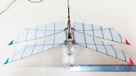
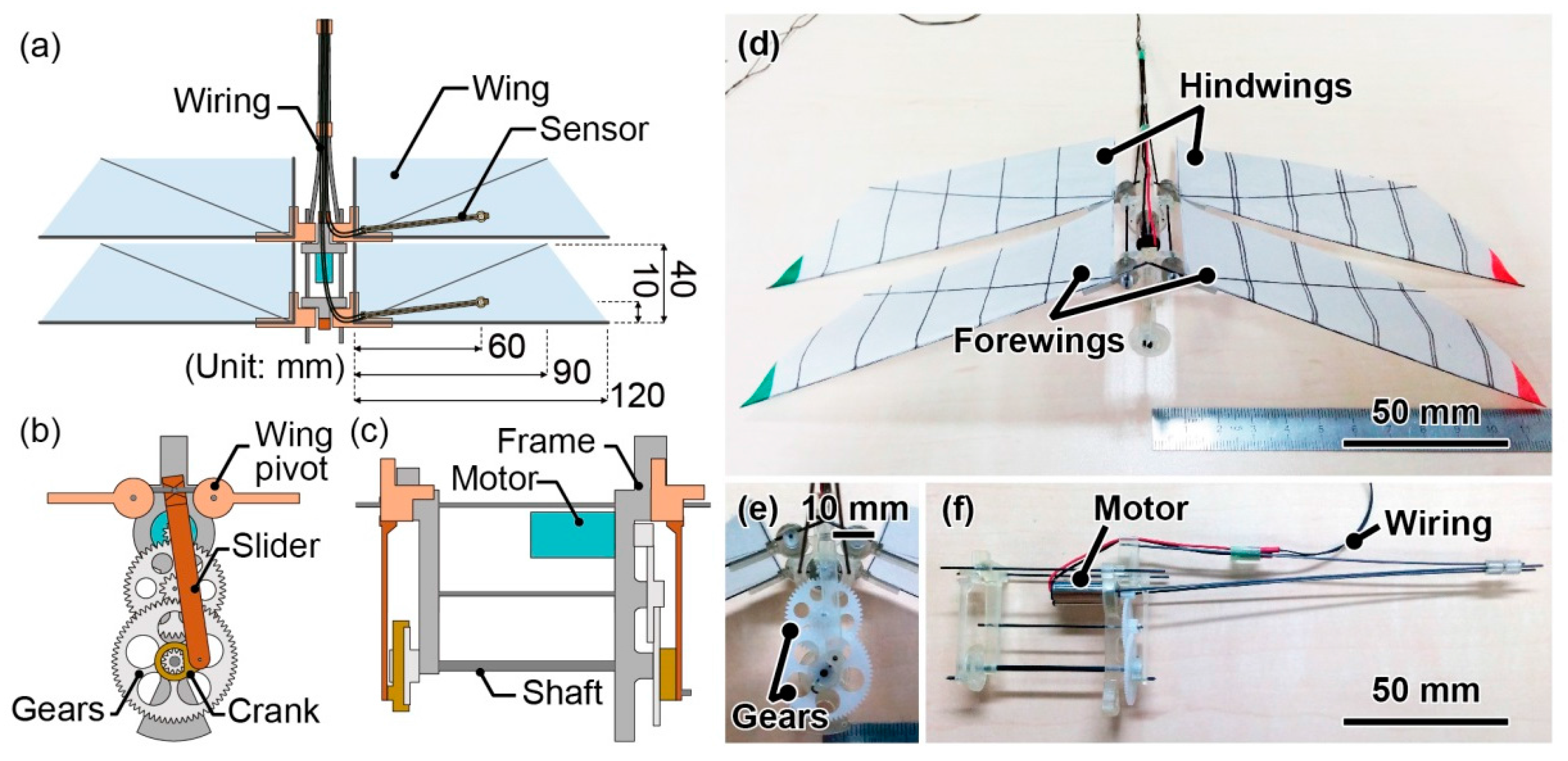
2. Design and Fabrication of the Dragonfly-Type Ornithopter

Figure 1 presents the design and photographs of the fabricated ornithopter. The ornithopter was based on our previous ornithopter design [23,24] and was unique in that there were four wings with phase angles. The wing aspect ratio (wingspan/wing chord), Reynolds number, and reduced number were designed to match those of an actual dragonfly as shown in Table 1. The reduced number k is defined as k = 1/AR·ψ, where AR is the aspect ratio between the wing span and the wing chord length, and ψ is the amplitude of the wing flapping, as shown in Table 1. A slider-crank mechanism was used to transform the rotational movement of a motor (Indoor Airplane World, Kanagawa Prefecture, Japan; MK0.7–1.7) through reducing gears into back-and-forth translational movement. The motor frame and other frame parts were fabricated by a 3D printer (Stratasys, Tokyo, Japan; Objet Eden 260 V). As shown in Figure 1c,f, the hindwing was attached to the motor frame. Then, the slider-crank motion was utilized to propagate the hindwing flapping motion. The gear to the slider-crank of the forewing also rotated through the shaft. Then, the phase angle between the forewing and hindwing was varied by changing the phase between the slider-cranks of the forewing and hindwing. The stroke plane angle was a right angle, and the wings flapped vertically to the body axis, in contrast to the motions of actual dragonflies [2]. As with the previous ornithopters, the proposed prototype also has a wing that is fixed at the wing root during flapping. Therefore, feathering motions were induced by the wing deformation. Each wing stroked in a plane perpendicular to the body axis with an amplitude of ±30°. The flapping frequency was approximately 12 Hz. The angular velocities during upstroke and downstroke were approximately symmetrical. The maximum relative airflow velocity was approximately 2.4 m/s at the half-wing length.
Figure 1. (a) Design of the dragonfly-type ornithopter with the MEMS differential pressure sensors on two wings; Mechanism of the wing flap using a motor—front (b) and side views (c); Changing the attachment point of the slider to the crank varied the phase angle. Photographs of the fabricated ornithopter prototype (df).
Aerospace 03 00004 g001
Table 1. Characteristics of two dragonfly species [2,4] and the ornithopter prototype. A large variety of properties exist for real dragonflies; the two cited here are examples.
CharacteristicsUnitA. Azuma, et al., 1985 [2]A. Azuma & T. Watanabe, 1988 [4]Ornithopter
Dragonfly species Sympetrum frequensAnax parthenope julius
Wing span smm66107276
Aspect ratio AR98.96.9
Flapping frequency fHz41.527.712
Amplitude ψdegrees4529.530
Wing load PN/m22.63.54.6
Reynolds number Re173717211670
Reduced number k0.140.190.28
The forewing and hindwing were identical and flapping on the same axis such that the pressure patterns were caused by the interaction of the forewing and hindwing rather than the differing shapes of the wings. The wing length and wing chord length were 120 and 40 mm, respectively, as shown in Figure 1a,d. The wings were constructed from Japanese paper with a thickness of 50 μm. The leading edge and body side were strengthened with carbon rods with diameters of 0.5 and 0.3 mm, respectively. A diagonal 0.3 mm rod was added to increase the stiffness. Both the forewing and the hindwing are fixed to wing pivots by the rods of the leading edge and body side. The wing pivots about the carbon bars of the frame. The distance between the forewing and hindwing was several millimeters. The weight of one wing was approximately 130 mg. The total weight of the ornithopter without the battery was 7.9 g, and the wing load was 4.6 N/m2, which is similar to that of dragonflies as shown in Table 1 and sufficiently light to fly with an external power supply [23,24].
As shown in Figure 2a, MEMS piezoresistive cantilever-type sensors were attached to the wing surface to serve as differential pressure sensors. The sensor chips were mounted on a 1-mm-diameter hole in the wing. The attachment point was a point at one-half of the wing length and one-quarter of the wing chord in each wing.
Figure 2. Photographs of the attached sensor (a); sensor chip (b); and the sensor element (c).
Aerospace 03 00004 g002
A Cu/polyimide/Cu flexible electrode was used as the sensor attachment on the wing surface. The sensor chip was electrically connected to the edge of the flexible electrode, and insulated wires were connected to the opposite side of the electrode edge. Beeswax was used to attach the electrode to the wing surface such that the sensor was positioned above the hole. Each signal was sent via two wires from the leading edge of the wing to the ornithopter tail. The signals were sent from the tail to an external bridge and amplifier circuit. The combined weight of the electrode and sensor chip was approximately 4.5 mg, less than 5% of the wing weight.
Figure 2b,c are photographs of the sensor chip and cantilever, respectively. A piezoresistive cantilever was constructed at the center to measure the differential pressure between the upper and lower surfaces of the cantilever based on the change in resistance due to cantilever deformation [25]. The sensor chip used in this study had dimensions of 1.5 × 1.5 × 0.3 mm3. The sensors were calibrated before being attached to the wing surface. The sensitivities to the differential pressure were approximately 1.0 × 10⁻⁴ Pa−1 from −40 to 40 Pa. The fabrication process and sensor calibration method were described in our previous work [25]. The differential pressure was expressed as a positive value when the pressure on the upper wing surface was lower than that on the lower wing surface.

3. Experiments and Results of the Tethered Ornithopter

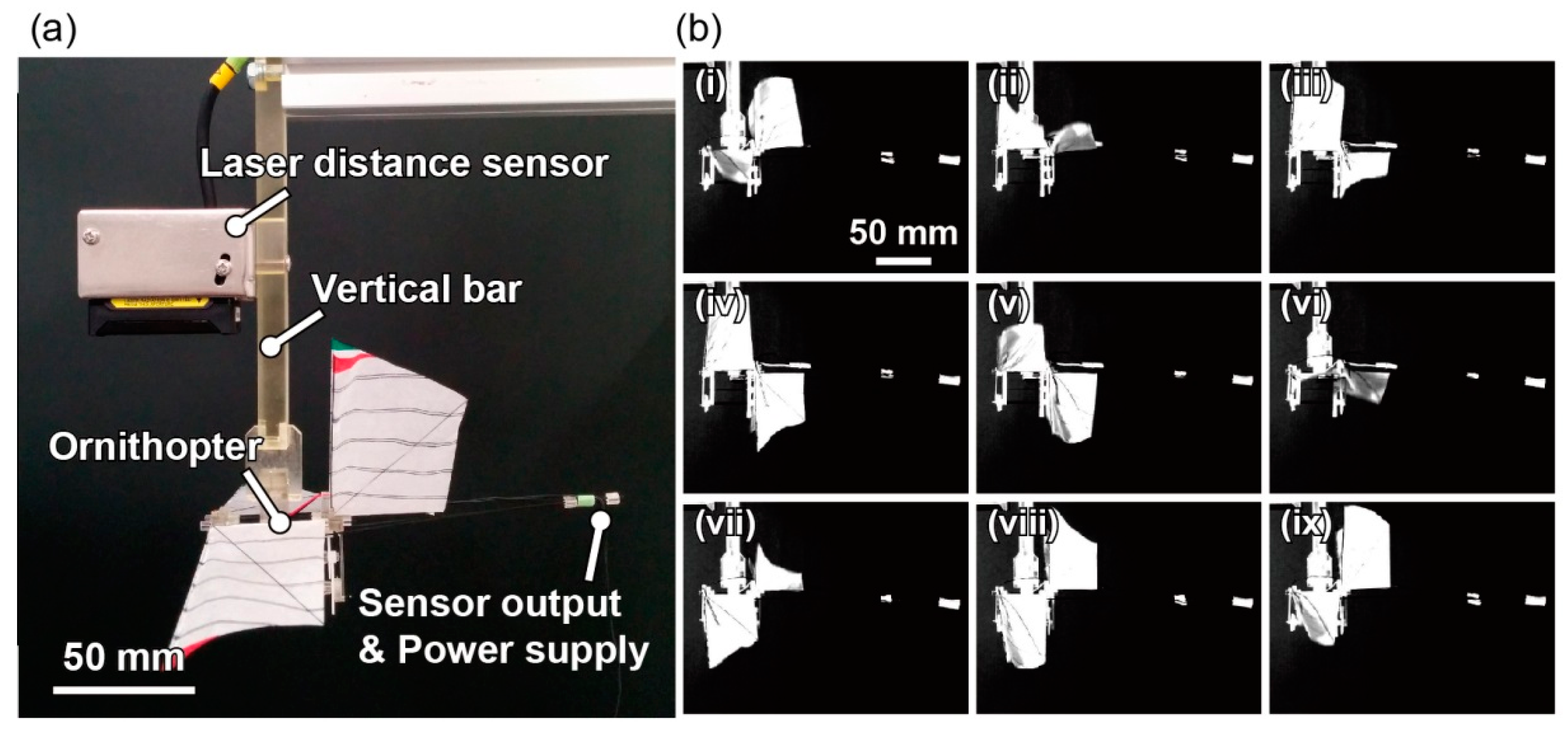
3.1. Experimental Setup

Using the ornithopter and sensor described above, we measured the differential pressures and evaluated the relationship between phase angle and aerodynamic performance during the tethered condition. The flapping motion from a lateral view was recorded using a high-speed camera (FASTCAM 1024 PCI, Photron, Tokyo, Japan; 1000 frames per second; 1024 × 1024 pixels) synchronized with the sensor signals. Five phase-angle experiments (0°, 30°, 90°, 180°, and 270°) were performed with positive and negative motor rotations. The flapping frequency was configured to 12 Hz by controlling the applied voltage to the motor for each phase angle. A laser proximity sensor (IL-065, Keyence, Osaka, Japan) was used to monitor the frequency. The experimental setup comprised a vertical bar for the attachment of the ornithopter on which the laser distance sensor was mounted as shown in Figure 3a. At the end of the bar, a clip held the ornithopter below the laser proximity sensor, aligning the slider tip with the laser beam. Cables for both sensor outputs and motor power supply were connected to the bridge circuits and an external power supply via the tail of the ornithopter to avoid disturbing the flapping motion.
Figure 3b presents high-speed camera images of the ornithopter with the angle set at 270° with positive rotation. The two wings flapped with approximately opposite phase, and both the forewing and hindwing feathered. Then, the positions of the wing tips of the leading edge and the trailing edge were plotted manually, as shown in Figure 4a. To make the data easier to understand, the x-axis of the position plots was inverted. The flapping angles were calculated from the leading edge wingtip motions of the forewing and hindwing. The feathering angles were also calculated by subtracting the flapping angles of the leading and trailing edges. Then, the phase angle between the forewing and hindwing was defined as the phase difference between the two calculated flapping angles. The calculated phase angle was 225° in this case, which was different from the angle that was set with the gear parts. The other phase angles observed during flapping motion also differed from the set angles, as shown in Figure 4b and Table 2. The torsion between the set and actual values was constant, approximately 45°. This torsion was attributed to the backlash or stiffness of the crank.
Figure 3. (a) Experimental setup in tethered motion; and (b) high-speed camera images of the ornithopter with the gear position set at 270° with positive rotation and a measured phase angle of 225°. The time interval is 10 ms.
Aerospace 03 00004 g003
Figure 4. (a) Side view of the trajectories of the wingtips of the ornithopter shown in Figure 3. The wing points were recorded every 5 ms; (b) relationship between the set gear position and the phase angle. The light green and blue plots are actual phase angles with positive and negative rotations, respectively; gray lines are theoretical values.
Aerospace 03 00004 g004
Table 2. Flapping performance in each setting angle during tethered motion. Rotation refers to the direction of motor rotation.
ConditionSetting Angle (Degrees)RotationPhase Angle (Degrees)Frequency (Hz)
1031511.4
2+30811.6
33028512.0
4+35512.0
59021512.0
6+5311.5
718011612.0
8+14311.5
92703211.5
10+22512.0
The differential pressure data from the sensors were smoothed using a digital bandpass filter of 0.1–48 Hz to eliminate temperature drift and electrical noise. When the power supply to the motor was stopped, the wings came to rest within a few milliseconds, and the sensor signal was unchanged. We evaluated the differential pressures of the approximately four final wingbeats before the flapping stopped.

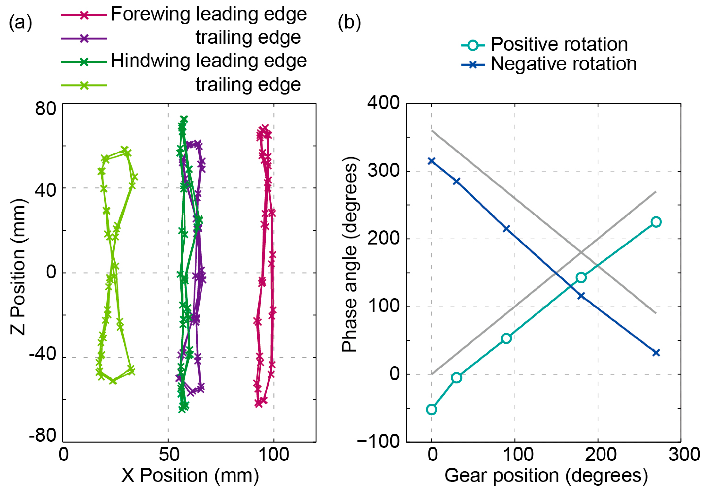
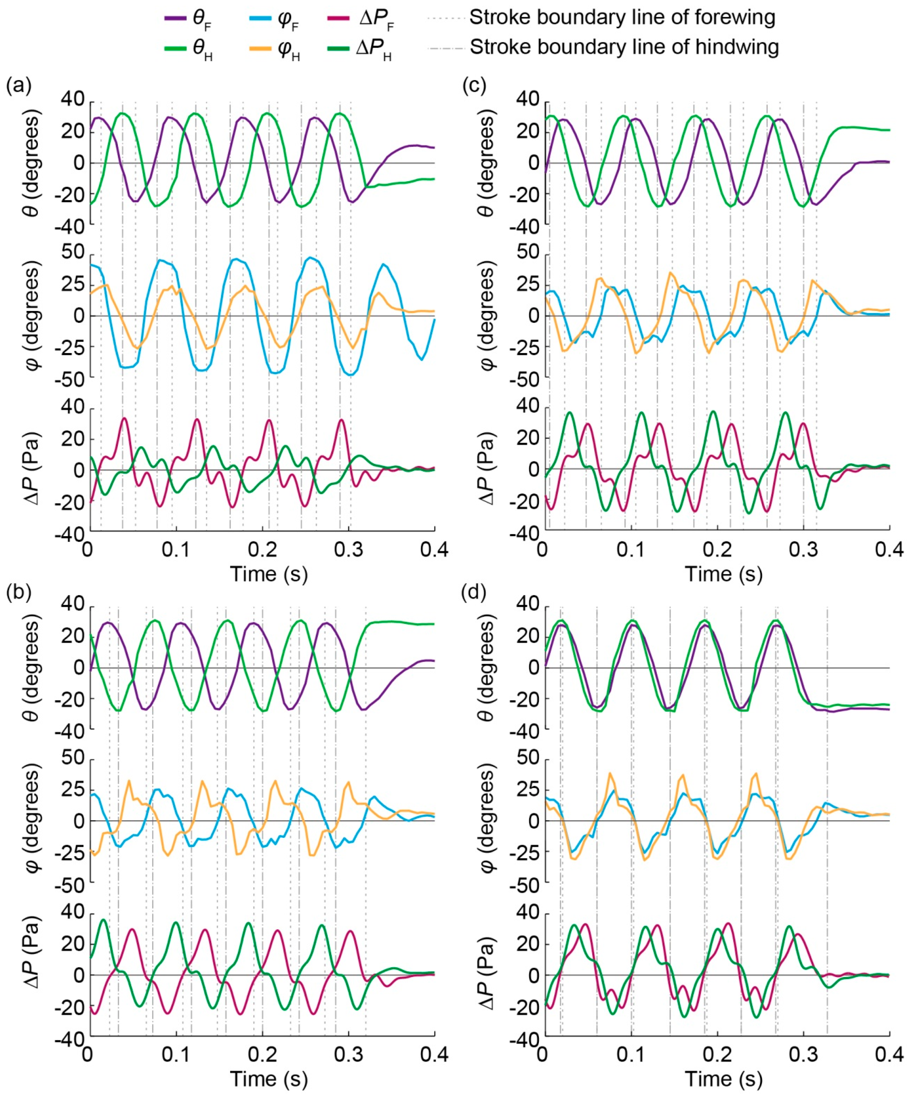
3.2. Experiments in Tethered Condition

Plots of the flapping angles, feathering angles, and differential pressures at the four characteristic phase angles are presented in Figure 5. As the four characteristic phase angles, we defined the forewing-lead, counterstroke, hindwing-lead, and in-phase modes when the phase angles were approximately 90°, 180°, 270°, and 0° (360°), respectively, as shown in Table 2. The phase angles in Figure 5a–d are 116°, 215°, 285°, and 355°, respectively, and correspond to the forewing-lead, counterstroke, hindwing-lead, and in-phase modes. The shapes of the flapping angles were similar even though the phase angles differed. It was also observed that each flapping angle was symmetric between the upstroke and the downstroke. The feathering angles were positive and negative during the upstroke and downstroke, respectively; the feathering angle was defined as positive when the leading edge was upward to the trailing edge. The feathering motions were passively performed by the wing deformation due to the aerodynamic force. The feathering angle of the forewing with a phase angle of 116° was relatively larger, whereas the other feathering angles varied from approximately −30° to +30°. This phenomenon was thought to arise because the feathering angle of the forewing with a phase angle of 116° was affected by the airflow due to the hindwing motion. It was observed that the feathering angle was symmetric between the upstroke and the downstroke. Moreover, the differential pressures differed. Other experiments with phase angles similar to each of the four characteristic phase angles yielded qualitatively identical results. The averaged absolute values of the differential pressures during one stroke were calculated as shown in Figure 6. The details of the characteristics of the four phase angles are described below.
In the forewing-lead mode, the differential pressure values were obviously lower on the hindwing. The average absolute differential pressures on the forewing and hindwing were approximately 13 and 8 Pa, respectively. These values indicated that the interaction greatly impeded the differential pressure on the hindwing, in agreement with the results of previous studies of robotic flappers in liquid [9] and CFD simulations [16].
In the counterstroke mode, the differential pressures were quite similar on each wing. Both average absolute differential pressures were also approximately 13 Pa. In contrast to the pressure characteristics of the forewing-lead mode, there were not two peaks during one stroke in both the forewing and hindwing.
Figure 5. Flapping angle, feathering angle, and differential pressure at the four characteristic phase angles during flapping motion. The light green and blue plots present the flapping angle of the forewing and hindwing, respectively; the orange and light blue plots display the feathering angles; the green and purple plots denote the differential pressures, and the gray lines illustrate the stroke boundary lines of the forewing and hindwing. The phase angles are 116° (a); 215° (b); 285° (c); and 355° (d) for the respective graphs.
Aerospace 03 00004 g005
Figure 6. Relationship between the phase angle of the ornithopter and averaged absolute values of differential pressure for each stroke.
Aerospace 03 00004 g006
In the hindwing-lead mode, the differential pressures had a similar shape, but that of the hindwing was slightly larger than that of the forewing. The average absolute differential pressures on the forewing and hindwing were approximately 14 and 15 Pa, respectively. The average of absolute value on the hindwing was largest on the hindwing among the four modes. Two peaks during one stroke were observed only for the forewing. This tendency agreed with the results of previous research on robotic flappers [9].
The in-phase mode is the cross point between the forewing-lead and hindwing-lead modes, as is counterstroke mode. Compared to counterstroke mode, there were critical differences in the aerodynamics during the in-phase mode with slight forewing-lead or hindwing-lead. The passive feathering of the wings suggests that the trailing edges lagged behind the leading edges. The hindwing continually led the forewing at the point between the two wing edges due to the passive feathering. Thus, the differential pressures had a shape similar to that of the hindwing-lead mode. In addition, the differential pressures were not symmetrical during upstroke and downstroke. This asymmetry was attributed to the difference in wing deformation and phase angle due to the motor characteristics and crank mechanism; even if the difference was slight, it would affect the aerodynamic performance of the in-phase mode relative to the other phase angles. The average absolute differential pressures were approximately 16 and 14 Pa, respectively. The differential pressure on the forewing reached a maximum value among the four modes near a phase angle of zero.
These experimental results demonstrated that the performance of the differential pressure on the forewing remained almost constant when the phase angle varied. However, the differential pressure obviously differed on the hindwing. The forewing-lead mode resulted in a smaller average value and two peaks in one stroke compared to the hindwing-lead mode. This was consistent with observations for robotic flappers [9]. These results confirmed that the aerodynamic effect of the phase angle remained even when the forewing and hindwing flapped on the right stroke plane angle with a passive feathering.

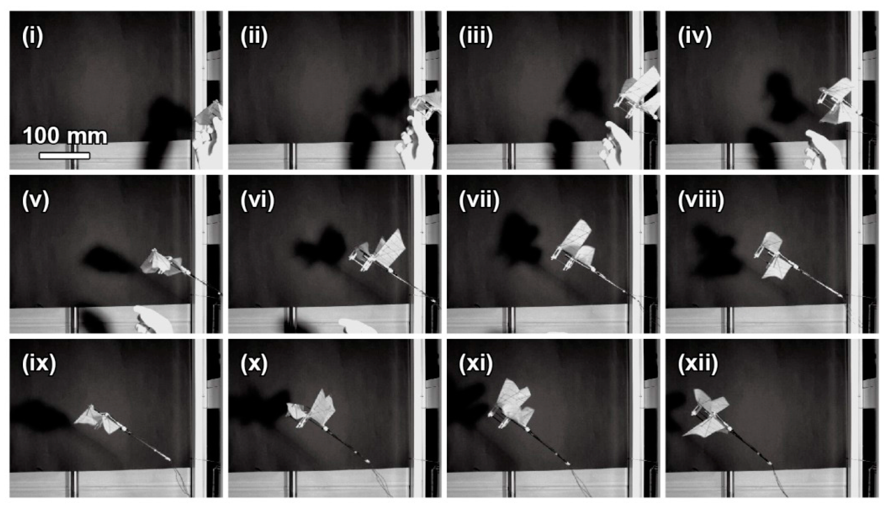
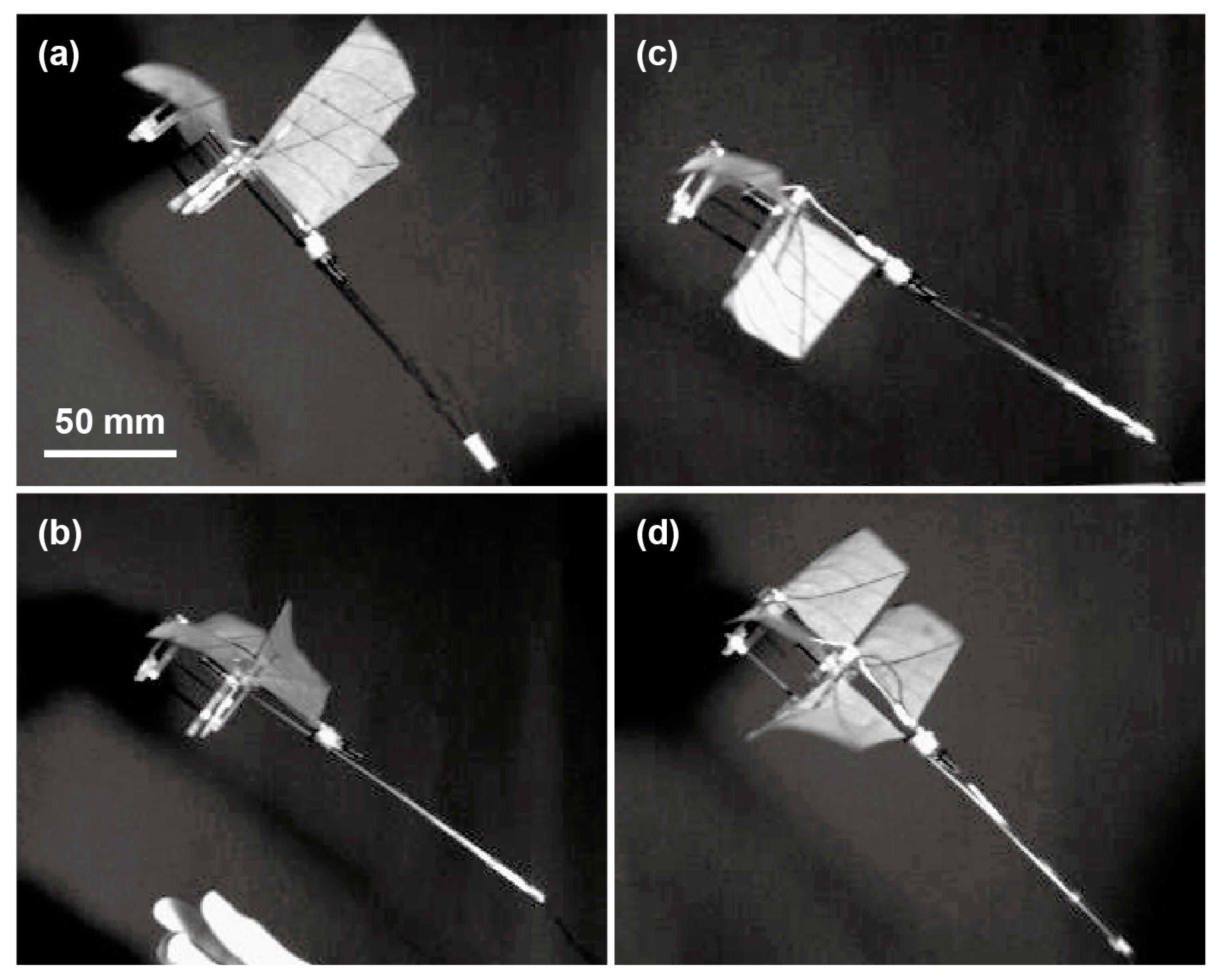
4. Demonstration of Free-Flight

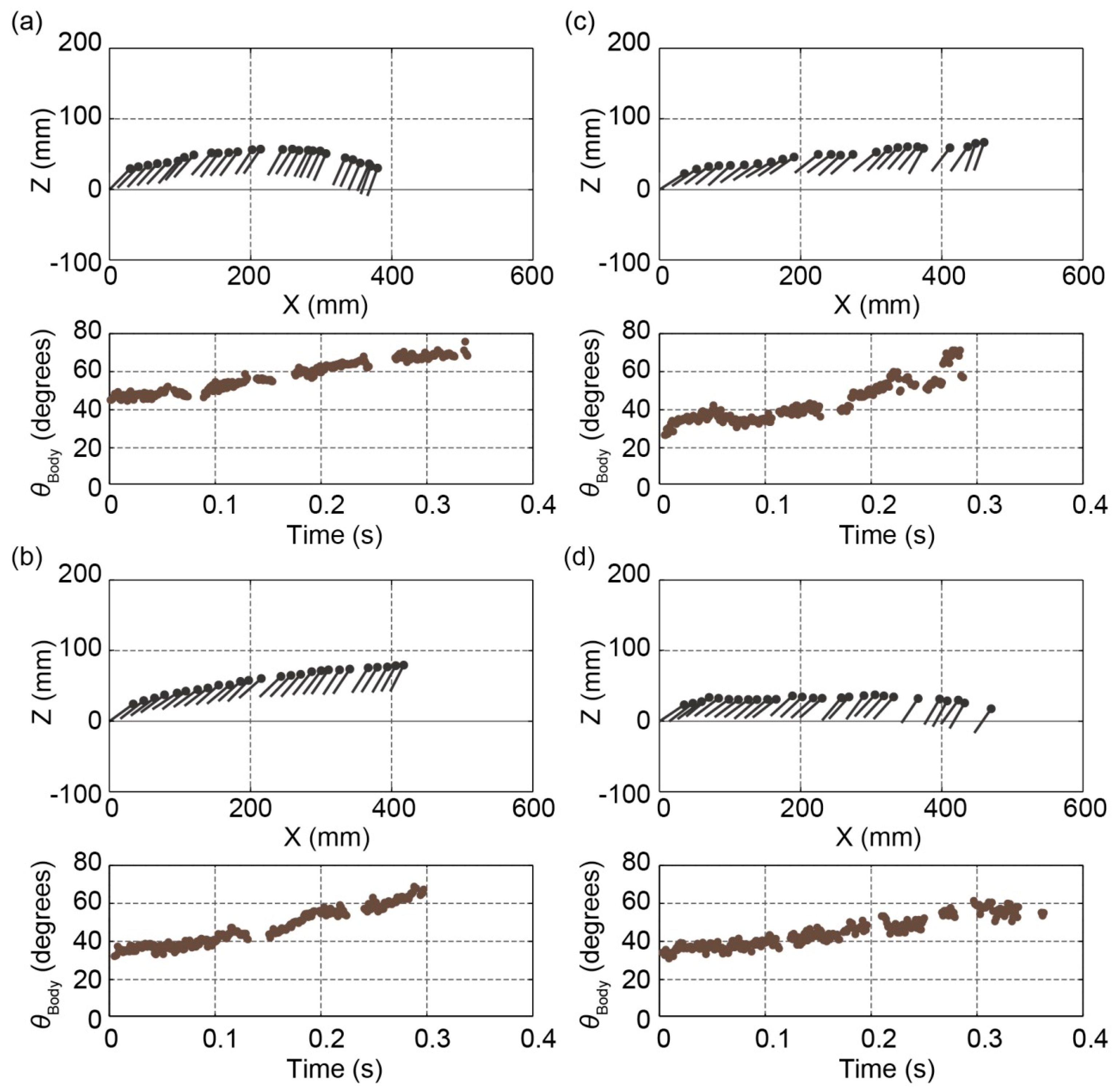
4.1. Flight Performance

Finally, we demonstrated differential pressure measurement in free-flight. For the free-flight experiments, the ornithopter was launched by hand with an initial flight velocity. At the launch from the hand, the body angle was approximately 30°–40°, and the horizontal velocity was 1–1.5 m/s. The lateral view of the flight trajectories was recorded using a high-speed camera, as with the experiments in the tethered condition. Four phase-angle experiments (0°, 30°, 180°, and 270°) were conducted with positive and negative motor rotations. Several flight experiments with the same phase angle were performed to confirm repeatability. The flapping frequency was set to 12 Hz using the laser proximity sensor before launching in every experiment. Due to the wires, the flight distance was limited to approximately 400 mm, which was three times the body length. The flight time and flapping cycle were approximately 0.25–0.4 s and 3–4 times, respectively.
Figure 7 presents the flight trajectory of the ornithopter with the angle set at 30° with negative rotation (high speed camera video is shown in Supplementary information). The wing tips were also tracked, as shown in Figure 8a. To make the data easier to understand, the x-axis of the flight position plots was inverted, as shown in Figure 4a. In actuality, the flights were filmed from right to left. The data had several missing points in the tracking for which the wing tip could not be accurately plotted. The frequency and phase angle were obtained from the fitting curve of the second- or third-order sum of the sinusoidal waves. The relationship between the gear position and the phase angle exhibited tendencies similar to those observed under tethered conditions, as shown in Figure 8b.
Figure 7. High-speed camera images of the ornithopter during free-flight with the gear position set at 30° with negative rotation and a measured phase angle of 271°. The time interval is 20 ms.
Aerospace 03 00004 g007
Figure 8. (a) Trajectories of the wing tips of the ornithopter, which is shown in Figure 7; (b) relationship between the set gear position and the phase angle.
Aerospace 03 00004 g008
Figure 9 shows the flight trajectories and body angles of the four free-flight modes—forewing-lead, counterstroke, hindwing-lead, and in-phase modes. The phase angles were 114°, 195°, 271°, and 10°, which corresponded to the conditions of 6, 14, 5, and 13 in Table 3. The dots and line represent the forewing pivot and the line between the forewing and hindwing pivots, respectively. The data were plotted every 10 ms. Some points were missing because of incomplete body point data, as with the wing tip plots. The x-axis of the flight position plots was also inverted. Other flight trajectories were similar to that of each characteristic phase angle. The flight performances are presented in Table 3. The flight velocity was computed and was generally constant and similar for all flights. The average flight velocities presented in Figure 9 were 1.0, 1.3, 1.5, and 1.3 m/s, respectively.
Figure 9. Flight trajectories and body angles in free-flight for the four modes. The phase angles in the four modes are 114° (a), 195° (b), 271° (c), and 10° (d), which correspond to conditions 6, 14, 5, and 13 in Table 3, respectively. Each angle corresponds to forewing-lead, counterstroke, hindwing-lead, and in-phase modes, respectively. The dot and line represent the forewing pivot and the line between two pivots, respectively. The data were plotted every 10 ms. Some points are missing because of incomplete body point data.
Aerospace 03 00004 g009
Table 3. Flapping performance in each angle setting during free-flight.
ConditionSetting Angle (Degrees)RotationPhase Angle (Degrees)Frequency (Hz)Initial Body Angle (Degrees)
1031814.926
231615.043
33028112.731
427711.627
527111.935
618011411.746
712511.541
8+13312.836
9+14012.733
10+13613.127
112701312.034
12812.536
131012.336
14+19512.032
15+20912.228
Figure 10. Zoom-in images of the flying ornithopter for the four modes. The captured images correspond to the forewing downstroke. The phase angles correspond to those in Figure 9.
Aerospace 03 00004 g010
Additionally, for the forewing-lead mode, the ornithopter began to stall in the middle of flight even if it moved upward at the beginning of the flight. Figure 10 shows zoom-in images of the flying ornithopter for the four modes corresponding to the flights shown in Figure 9. Each captured image corresponds to the forewing downstroke.
The body angle increased with time during most flights. This increase was attributed to the location of the center of gravity rearward relative to the optimal position due to the weight of the connecting wires. However, there was little tensional force by the wires on the ornithopter. In some excluded flights, the tensional force pulled backward and decreased the body angle quite suddenly. The repeatability of the trajectory of the ornithopter was confirmed for each phase angle.
Providing that the flight speed of the ornithopter was 1.5 m/s and the flapping frequency was 12 Hz during free flight, the non-dimensional number representing the ratio of the flight speed to the wingtip speed was 0.31. The value for a real dragonfly is calculated as 0.24 [2]. Furthermore, the value varies from 0.15 to 0.6 according to the flight speed [4]. The values obtained during flying at a speed of approximately 1.0 m/s are similar to that of the ornithopter.

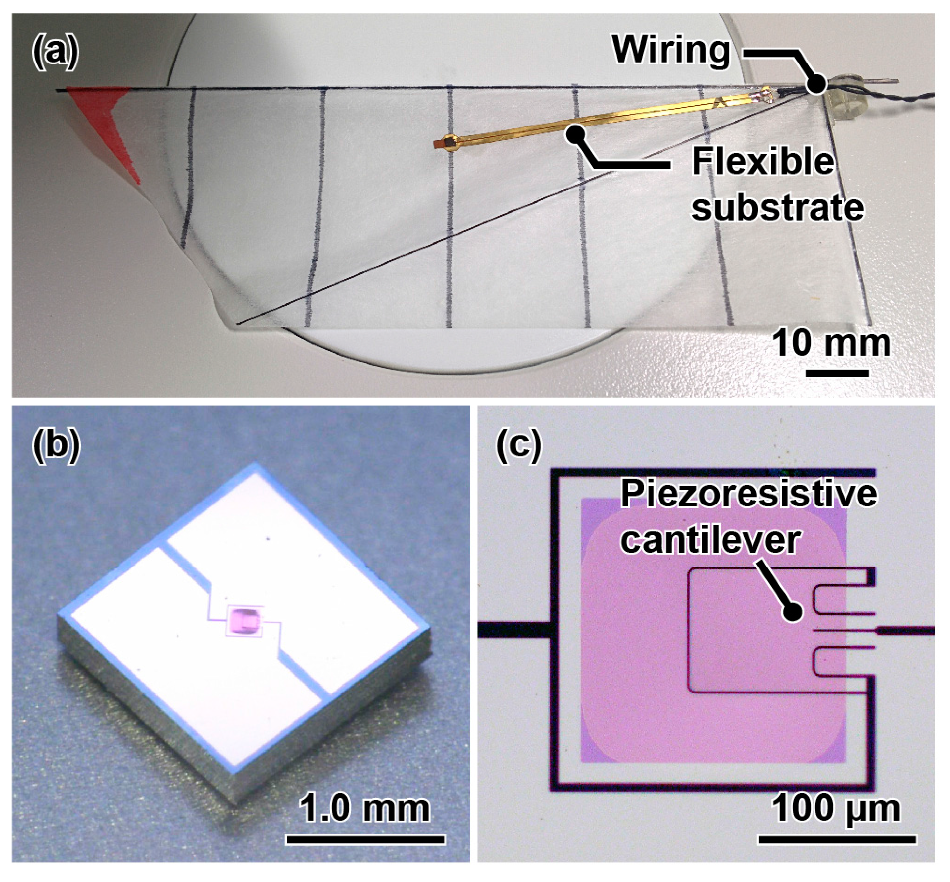
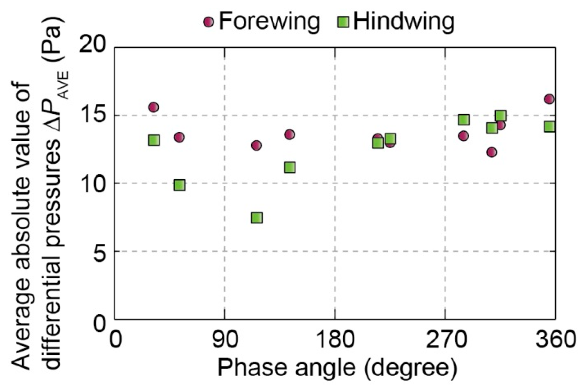
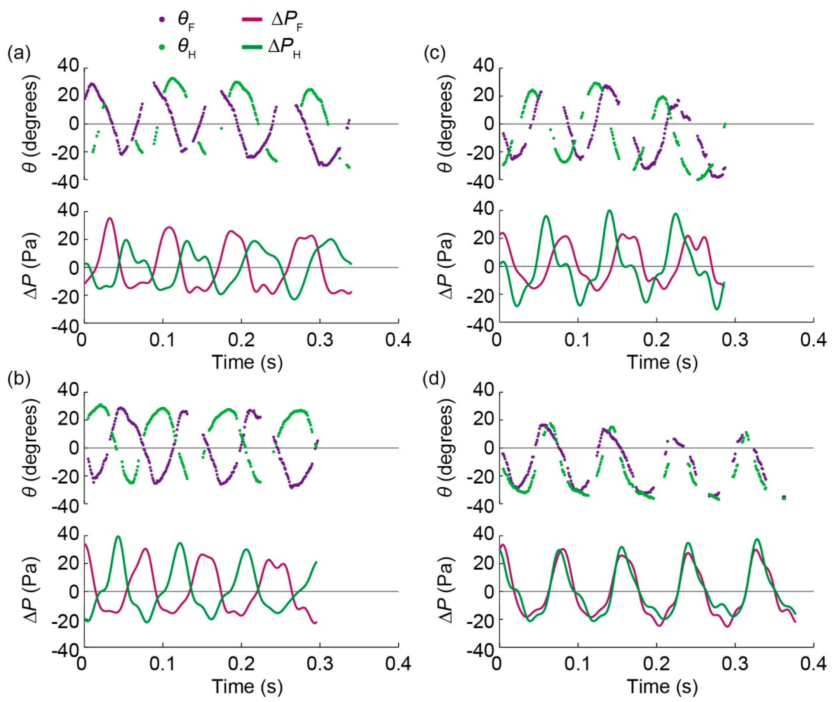
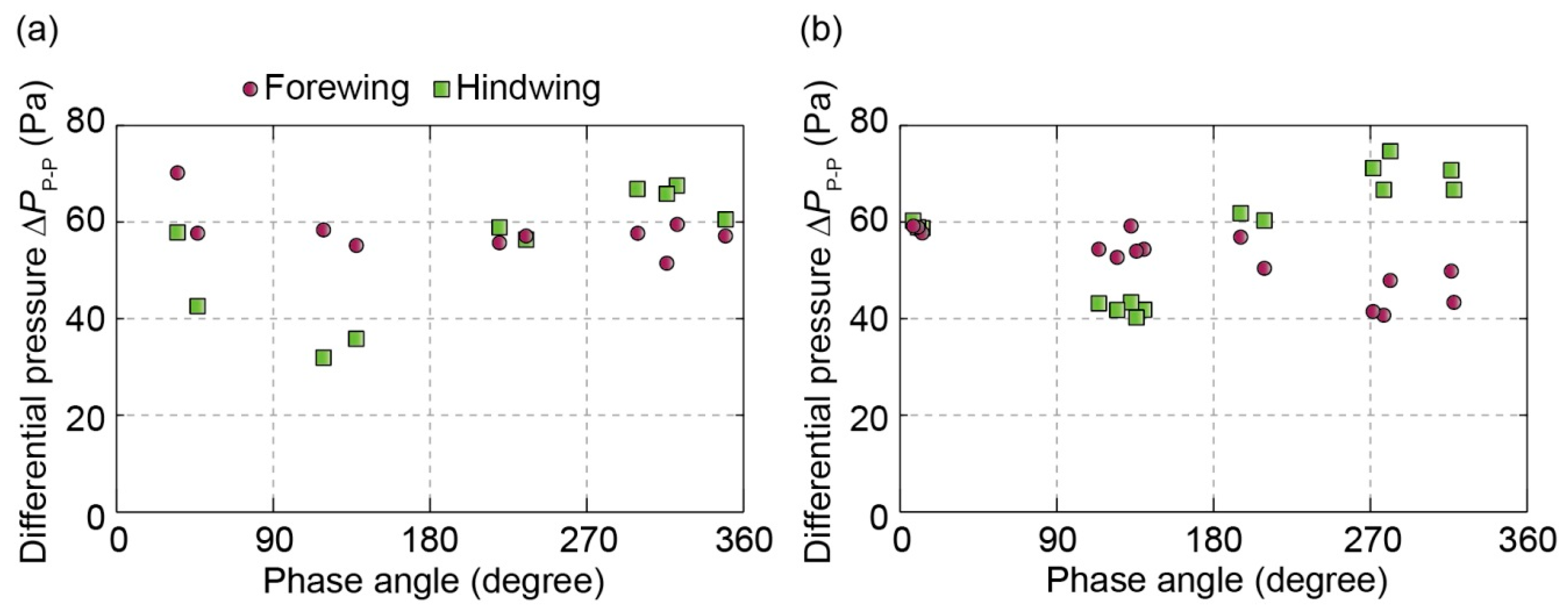
4.2. Differential Pressure Measurement

The differential pressure data from the sensors were measured and synchronized with the video data as with the tethered experiments. A digital bandpass filter of 1–48 Hz was applied to the measured data. The measured flapping angles and differential pressures shown in Figure 11 correspond to the flights shown in Figure 9. Some points were missing for the same reason described for the plots of Figure 9. In the case of free-flight, it was difficult to obtain a zero point immediately after the wings stopped beating. The differential pressures were also considered asymmetrical during upstroke and downstroke [23]. Thus, the uncertainty of the zero point would not be negligible. However, the shapes of the differential pressures were basically correct. We compared the shapes of the characteristic four phase angles and the peak-to-peak values of differential pressures during one stroke, which also had no dependence on zero point error, as shown in Figure 12. In the tethered condition, the relationship of the peak-to-peak values had similar tendencies to those of the average values as shown in Figure 6 and Figure 12.
Figure 11. Flapping angles and differential pressures of forewing and hindwing for the four modes: (a) forewing-lead; (b) counterstroke; (c) hindwing-lead, and (d) in-phase. These modes correspond to those in Figure 9.
Aerospace 03 00004 g011
Figure 12. Relationship between the phase angle and peak-to-peak value of the differential pressure during one stroke (a) in the tethered condition and (b) in free-flight.
Aerospace 03 00004 g012
For all four phase angles, the flapping angle change was asymmetrical during upstroke and downstroke, which was due to the inflow formed by the forward flight and positive body angle. The angular velocity was high for the upstroke and low for the downstroke. The shapes of the differential pressures on the hindwing were similar to those of the tethered condition. The feathering angles also had a tendency to be asymmetrical during the upstroke and downstroke.
The peak-to-peak values of the differential pressure on the hindwing were the largest in hindwing-lead mode. The values on the hindwing in free-flight were larger than those in the tethered condition. They were also the smallest in the forewing-lead mode. However, the shapes of the differential pressures on the forewing differed from those in the tethered condition at several points. For example, two peaks during one stroke were observed in counterstroke mode. The peak-to-peak values of the differential pressure decreased as the phase angle increased, whereas the values were similar to one another in the tethered condition. The direct aerodynamic effect of airflow from the hindwing to the forewing in free-flight was considered small because the ornithopter flew forward. The difference in the peak-to-peak values on the forewing between free-flight and tethered condition was attributed to the whole motion of the ornithopter, including the body angle and flight velocity, which determined the angle of attack and inflow velocity.

4.3. Discussion

Assuming that the aerodynamic force on each wing corresponds to the measured differential pressures, the aerodynamic force on the hindwing was found to be small in the forewing-lead mode. This tendency agrees with the results of previous research on robotic flappers [9] and CFD simulations [14,15]. The stalling of the ornithopter in the forewing-lead mode can be attributed to this relatively small vertical aerodynamic force. This result would indicate that a real dragonfly does not use the forewing-lead mode in flight for the same reason. The peak-to-peak values of the differential pressures in counterstroke mode changed only slightly during the tethered condition and free-flight. Due to the advantage of the small force fluctuations and the body oscillation [16], flight at a low velocity—including hovering—could be achieved with suitable body and feathering angles. However, the peak-to-peak value of the differential pressures on the hindwing in the hindwing-lead mode during a free-flight was the largest among the four characteristic modes. This effect was more apparent in the free-flight than in the tethered mode. This signifies that the hindwing in the hindwing-lead mode during forward flight attains the largest aerodynamic force among the four characteristic flight modes. If the wing area of the hindwing is larger than that of the forewing, as it is the case with dragonflies, these results suggest that the hindwing-lead mode is suitable for forward flight. As shown in Figure 9, the average velocity of the flight was at the maximum when the phase angle was in the hindwing-lead mode. This tendency agrees with the flight performance of a real dragonfly, which uses the hindwing-lead mode in forward flight [4,7]. However, it is difficult to conclude whether the ornithopter in the hindwing-lead mode can fly with the highest flight velocity among the four flight modes because of the hand launch and short flight distance.
As the next step, we will investigate the relationship between the differential pressure and flight performance when the phase angle is varied using an ornithopter that can fly long distances with repeatable initial flight velocity. An airflow visualization, such as particle image velocimetry in a wind tunnel at a certain airflow velocity, would also be sufficient to verify this aerodynamic phenomenon, including the relationship between the differential pressure and its suitable flight velocity, as in the case of robotic wings [9,10,11]. Additionally, we will evaluate the power efficiency of flapping motion with each phase angle by monitoring the applied voltage and current values in detail.
The ornithopter flapped its wings in the perpendicular stroke plane with passive feathering motion. Changes in the phase angle lead to different flight performances without active controls of pitching, feathering, and other wing kinematics. Changing the phase angle is simple so that the ornithopter does not require a complex flapping mechanism. Provided that the flapping motions are controlled independently for the forewing and the hindwing, the phase angle can be actively altered during the flight of a dragonfly-type four-wing ornithopter.
Applying the phase angle to insect-sized flying robots requires a consideration of the divergences between experimental robotic flappers/CFD simulations modeled after a dragonfly and current actual flying robots. For example, many flying robots flap their wings in perpendicular stroke planes without complex active controls of pitching and feathering because of weight limitations [18,19,20,21,22]. Then, passive feathering motion due to wing deformation is utilized. Previous research has suggested that even slight differences in the phase angle may alter aerodynamic performance. It is not clear if actual airframes utilize the effect of the phase angle phenomena like dragonflies.

5. Conclusions

The aerodynamic performance of forewing and hindwings on a dragonfly-type ornithopter were evaluated using MEMS differential pressure sensors. In the tethered condition, the generated differential pressures on the wings varied at different phase angles, particularly on the hindwing. The differential pressure was smallest on the hindwing in forewing-lead mode and was considerably larger on the hindwing in hindwing-lead mode. In counterstroke mode, the differential pressure on the forewing and hindwing was similar.
As an experimental validation, we measured the differential pressure in free-flight. The results demonstrated that the forewing-lead mode does not attain sufficient aerodynamic force on the hindwing as with the tethered condition and resulted in stalling during flight. These experiments also indicated that hindwing-lead mode was suitable for forward flight at a certain flight velocity similar to that of actual dragonflies.
An ornithopter that can fly longer distances would be an effective platform to test the relationship between the phase angle and various flight mode performances. The methodology focusing on the wing interaction of the phase angle could facilitate the development of an artificial four-wing type ornithopter that achieves a high flight performance like a real dragonfly.

Supplementary Files

Supplementary File 1

Acknowledgments

This study was partly supported by JSPS KAKENHI Grant Number 25000010 and the Mizuho Foundation for the Promotion of Sciences. EB photo mask fabrication was performed using the EB lithography apparatus at the VLSI Design and Education Center (VDEC) at the University of Tokyo. Also we acknowledge partial support from Swiss National Competence Centers in Research (NCCR) Robotics.

Author Contributions

All authors contributed to the design, data analysis and preparation of the manuscript; Alice Concordel and Hidetoshi Takahashi performed the ornithopter fabrication and measured differential pressures of the ornithopter in flapping experiments; Jamie Paik and Isao Shimoyama planned and supervised the project.

Conflicts of Interest

The authors declare no conflict of interest.

References

  1. Alexander, D.E. Unusual Phase-Relationships between the Forewings and Hindwings in Flying Dragonflies. J. Exp. Biol. 1984, 109, 379–383. [Google Scholar]
  2. Azuma, A.; Azuma, S.; Watanabe, I.; Furuta, T. Flight Mechanics of a Dragonfly. J. Exp. Biol. 1985, 116, 79–107. [Google Scholar]
  3. Somps, C.; Luttges, M. Dragonfly Flight—Novel Uses of Unsteady Separated Flows. Science 1985, 228, 1326–1329. [Google Scholar] [CrossRef] [PubMed]
  4. Azuma, A.; Watanabe, T. Flight Performance of a Dragonfly. J. Exp. Biol. 1988, 137, 221–252. [Google Scholar]
  5. Wakeling, J.M.; Ellington, C.P. Dragonfly flight. II. Velocities, Accelerations and Kinematics of Flapping Flight. J. Exp. Biol. 1997, 200, 557–582. [Google Scholar] [PubMed]
  6. Ruppell, G. Kinematic Analysis of Symmetrical Flight Maneuvers of Odonata. J. Exp. Biol. 1989, 144, 13–42. [Google Scholar]
  7. Wang, H.; Zeng, L.; Liu, H.; Yin, C. Measuring Wing Kinematics, Flight Trajectory and Body Attitude during Forward Flight and Turning Maneuvers in Dragonflies. J. Exp. Biol. 2003, 206, 745–757. [Google Scholar] [CrossRef] [PubMed]
  8. Thomas, A.L.R.; Taylor, G.K.; Srygley, R.B.; Nudds, R.L.; Bomphrey, R.J. Dragonfly Flight: Free-Flight and Tethered Flow Visualizations Reveal a Diverse Array of Unsteady Lift-Generating Mechanisms, Controlled Primarily via Angle of Attack. J. Exp. Biol. 2004, 207, 4299–4323. [Google Scholar] [CrossRef] [PubMed]
  9. Maybury, W.L.; Lehmann, F.O. The Fluid Dynamics of Flight Control by Kinematic Phase Lag Variation between Two Robotic Insect Wings. J. Exp. Biol. 2004, 207, 4707–4726. [Google Scholar] [CrossRef] [PubMed]
  10. Usherwood, J.R.; Lehmann, F.O. Phasing of Dragonfly Wings Can Improve Aerodynamic Efficiency by Removing Swirl. J. R. Soc. Interface 2008, 5, 1303–1307. [Google Scholar] [CrossRef] [PubMed]
  11. Hu, Z.; Deng, X.Y. Aerodynamic Interaction between Forewing and Hindwing of a Hovering Dragonfly. Acta Mech. Sin. 2014, 30, 787–799. [Google Scholar] [CrossRef]
  12. Zheng, Y.; Wu, Y.; Tang, H. Force Measurements of Flexible Tandem Wings in Hovering and Forward Flights. Bioinspir. Biomim. 2015, 10. [Google Scholar] [CrossRef] [PubMed]
  13. Sun, M.; Lan, S.L. A Computational Study of the Aerodynamic Forces and Power Requirements of Dragonfly (Aeschna Juncea) Hovering. J. Exp. Biol. 2004, 207, 1887–1901. [Google Scholar] [CrossRef] [PubMed]
  14. Wang, J.K.; Sun, M. A Computational Study of the Aerodynamics and Forewing-Hindwing Interaction of a Model Dragonfly in Forward Flight. J. Exp. Biol. 2005, 208, 3785–3804. [Google Scholar] [CrossRef] [PubMed]
  15. Huang, H.; Sun, M. Dragonfly Forewing-Hindwing Interaction at Various Flight Speeds and Wing Phasing. AIAA J. 2007, 45, 508–511. [Google Scholar]
  16. Wang, Z.J.; Russell, D. Effect of Forewing and Hindwing Interactions on Aerodynamic Forces and Power in Hovering Dragonfly Flight. Phys. Rev. Lett. 2007, 99. [Google Scholar] [CrossRef] [PubMed]
  17. Broering, T.; Lian, Y.-S. The Effect of Phase Angle and Wing Spacing on Tandem Flapping Wings. Acta Mech. Sin. 2012, 28, 1557–1571. [Google Scholar] [CrossRef]
  18. Nakata, T.; Liu, H.; Tanaka, Y.; Nishihashi, N.; Wang, X.; Sato, A. Aerodynamics of a Bio-Inspired Flexible Flapping-Wing Micro Air Vehicle. Bioinspir. Biomim. 2011, 6. [Google Scholar] [CrossRef] [PubMed]
  19. De Croon, G.C.; Groen, M.A.; de Wagter, C.; Remes, B.; Ruijsink, R.; van Oudheusden, B.W. Design, Aerodynamics and Autonomy of the DelFly. Bioinspir. Biomim. 2012, 7. [Google Scholar] [CrossRef] [PubMed]
  20. Ma, K.Y.; Chirarattananon, P.; Fuller, S.B.; Wood, R.J. Controlled Flight of a Biologically Inspired, Insect-Scale Robot. Science 2013, 340, 603–607. [Google Scholar] [CrossRef] [PubMed]
  21. Keennon, M.; Klingebiel, K.; Won, H.; Andriukov, A. Development of the Nano Hummingbird: A Tailless Flapping Wing Micro Air Vehicle. In Proceedings of the 50th AIAA Aerospace Sciences Meeting Including the New Horizons Forum and Aerospace Exposition, Nashville, TN, USA, 9–12 January 2012.
  22. Tanaka, H.; Shimoyama, I. Forward Flight of Swallowtail Butterfly with Simple Flapping Motion. Bioinspir. Biomim. 2010, 5. [Google Scholar] [CrossRef] [PubMed]
  23. Takahashi, H.; Aoyama, Y.; Ohsawa, K.; Tanaka, H.; Iwase, E.; Matsumoto, K.; Shimoyama, I. Differential Pressure Measurement Using a Free-Flying Insect-Like Ornithopter with an MEMS Sensor. Bioinspir. Biomim. 2010, 5. [Google Scholar] [CrossRef] [PubMed]
  24. Takahashi, H.; Sato, K.; Matsumoto, K.; Shimoyama, I. Measuring Differential Pressures with Multiple MEMS Sensors during Takeoff of an Insect-Like Ornithopter. J. Biomech. Sci. Eng. 2014, 9. [Google Scholar] [CrossRef]
  25. Takahashi, H.; Minh-Dung, N.; Matsumoto, K.; Shimoyama, I. Differential Pressure Sensor Using a Piezoresistive Cantilever. J. Micromech. Microeng. 2012, 22, 991–1008. [Google Scholar] [CrossRef]
  26. Takahashi, H.; Matsumoto, K.; Shimoyama, I. Differential Pressure Distribution Measurement for the Development of Insect-Sized Wings. Meas. Sci. Technol. 2013, 24. [Google Scholar] [CrossRef]
  27. Takahashi, H.; Tanaka, H.; Matsumoto, K.; Shimoyama, I. Differential Pressure Distribution Measurement with an MEMS Sensor on a Free-Flying Butterfly Wing. Bioinspir. Biomim. 2012, 7. [Google Scholar] [CrossRef] [PubMed]

