6.1. Annular-Ducted Fan Lift System in Hover Mode
The annular-ducted fan lift system in hover mode was simulated.
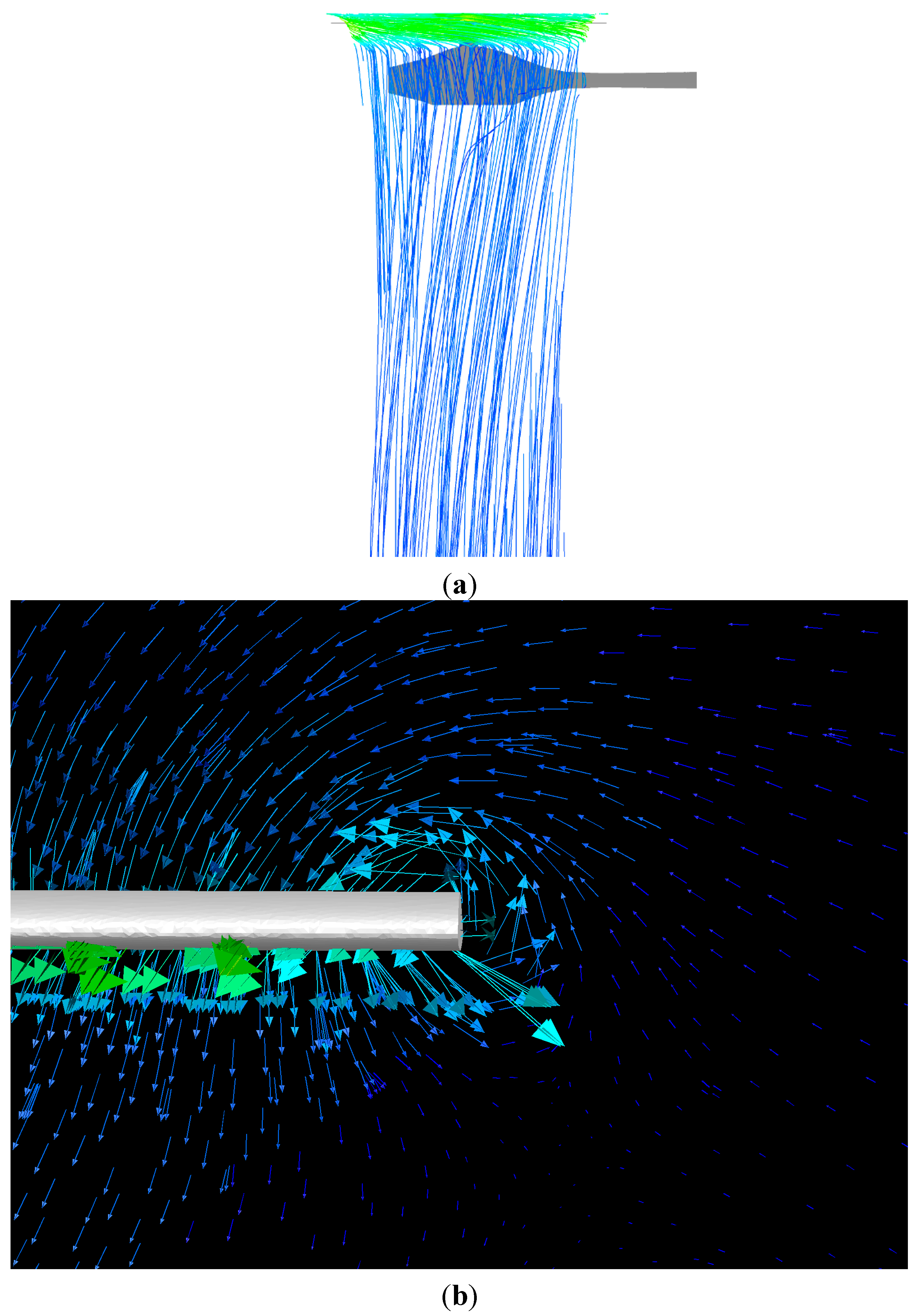
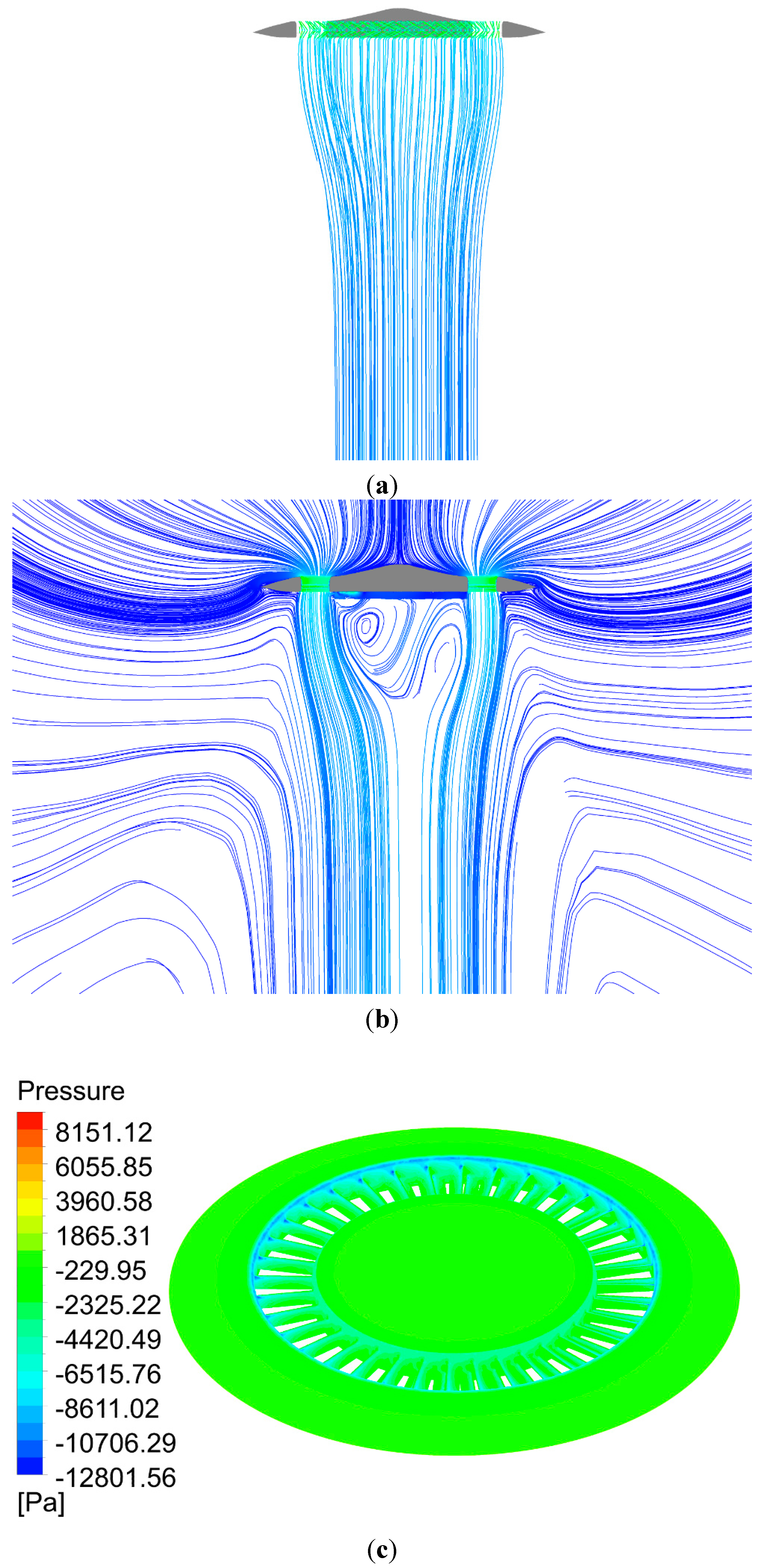
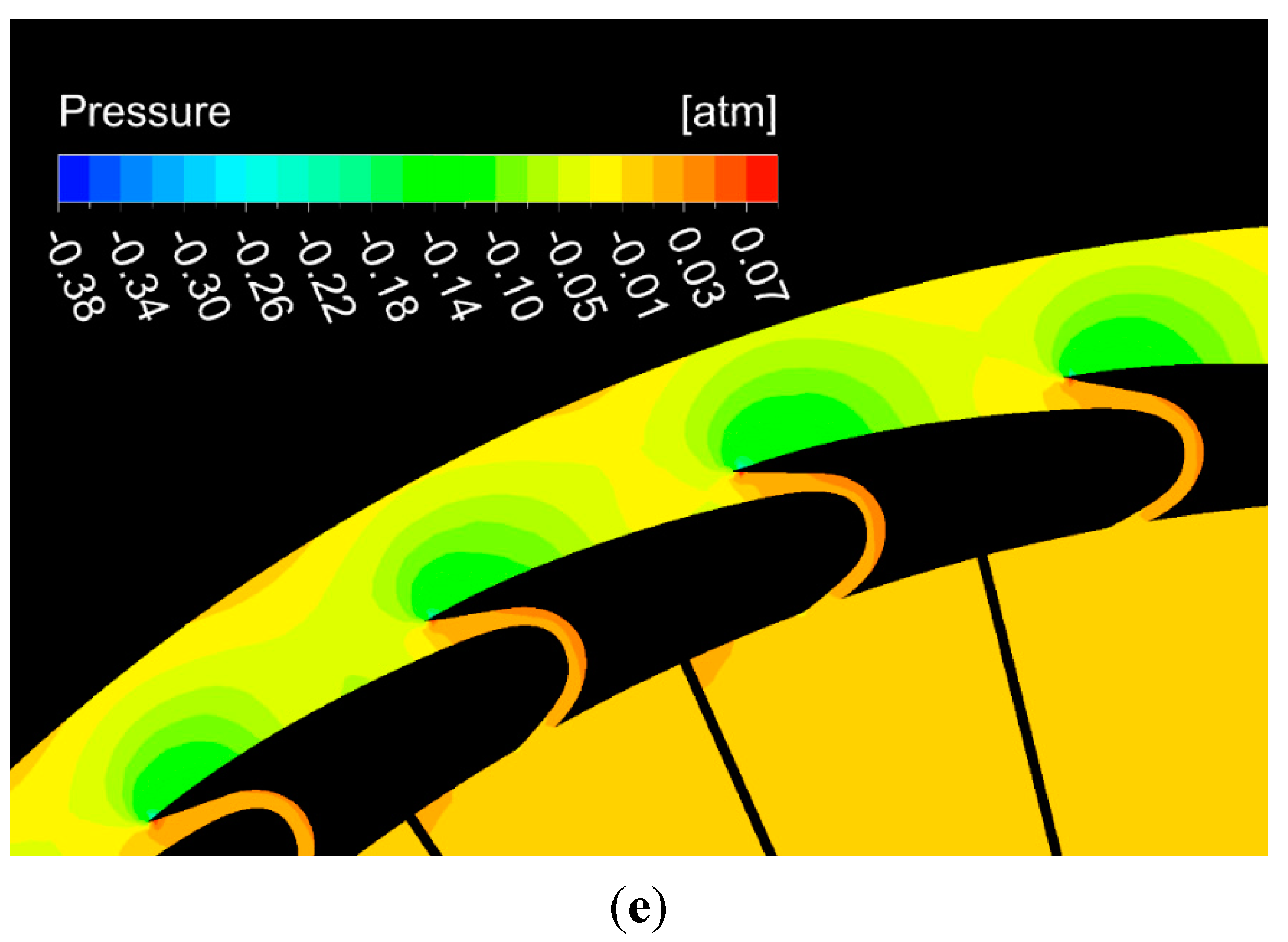
Figure 8 shows the streamlines and static pressure contour on the surface of the aircraft and inside the lift fan system in hover mode. The 3D streamlines through the annular duct show that the lift fan system generates a long wake in the flow field (
Figure 8a). The wake is not swirling due to the counter rotation of the two fans; thus, there is no energy wasted on swirling air. The vortexes at the fan tips are also eliminated by the duct walls. The annular duct has a diffused outlet, which prevents the downstream flow from contraction and increases the duct lift. The wake streamlines still look a little contracted in
Figure 8a because of the low pressure beneath the central fuselage, but the cross-sectional area of the flow is not decreased according to the surface streamlines in the central plane (
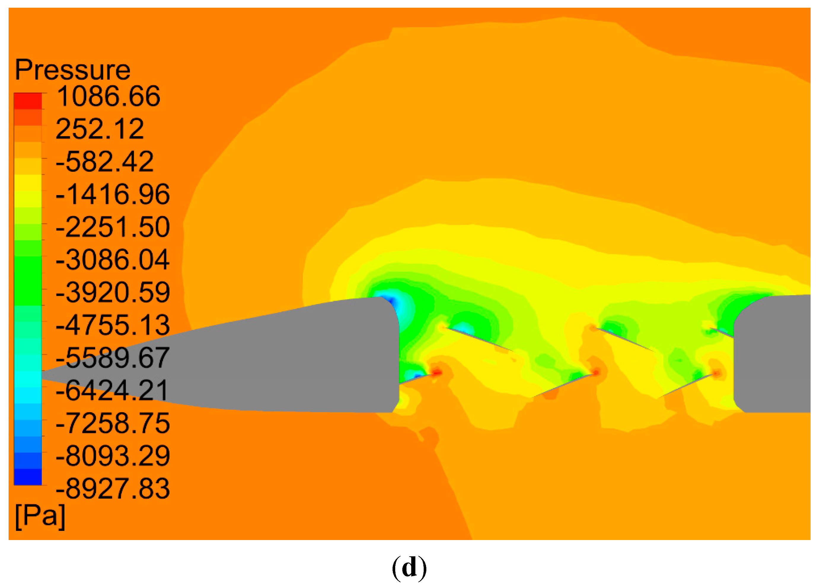
Figure 8b). The pressures on the upper surfaces of the duct walls and fan blades are low (
Figure 8c,d). The low pressure caused by the induced flow on the inlet lips of the duct and upper surface of the peripheral wing generates duct lift (
Figure 8b,d).
For the 3-m annular duct, when the two fans contra rotate at +103 and −99 rpm producing the same torque, the system lift is
T = 102,408 N (10.433 tons, the maximum weight of the Apache helicopter), among which fan thrust is
Trotor = 58,361 N; thus, according to Equation (4) of the momentum theory:
Figure 8.
(a) Three-dimensional streamlines in front of the central plane in hover mode; (b) surface streamlines in the central plane of the aircraft; (c) static pressure on the upper surface of the fans, duct, fuselage and peripheral wing; (d) pressure contour inside the annular-ducted lift fan system.
The induced power according to Equation (5),
where fan area
A = 103.62 m
2.
Compared to the Apache rotor, according to Equation (7):
where
Aunducted = 167.33 m
2 for the rotor of the Apache helicopter.
It can be seen that, although the disk area of the Apache rotor (167.33 m2) is much larger than that of the lift fan system (103.62 m2), the induced power for the annular-ducted lift fan system to provide the same lift is even lower.
The moment of the upper fan is obtained as 98,925 N m, and the moment of the lower fan is 98,292 N m; thus, the mechanical shaft power of the lift fan system:
Therefore, the fan efficiency is η = 1548/2085 = 0.74. The lift efficiency T/Pshaft = 10,433/2085 = 5.00 kg/kW.
For the AH-64E Apache helicopter, it is known that the maximum weight is T = 10.433 ton (102,243 N), power P = 2676 kW, A = 168.11 m2, so the rotor efficiency η = Pinduced/P = 0.603, and the lift efficiency T/P = 3.89 kg/kW. Therefore, compared to the Apache rotor, the 3-m lift fan system is more efficient and can save 22% of the power.
The reasons why the annular-ducted fan can save energy are two-fold [
20]: (1) elimination of rotor tip vortex loss, wake swirling loss and wake coning loss: the duct not only eliminates fan tip vortex, but also prevents the downstream flow from contraction; and (2) additional duct lift. Beside the fan thrust, there is an additional duct lift caused by the low pressure on the duct inlet lips and the upper surfaces of fuselage and peripheral wing, which can be almost as much as the fan thrust. The additional duct lift helps reduce the required fan thrust, thus reducing the drag on fan blades and the corresponding power required to run the fan. According to the simulation results, about 1/4 of the lift comes from the upper fan, 1/4 from the lower fan, 1/4 from the annular duct lips and 1/4 from the peripheral wing due to the induced flow over the wing (
Figure 8b,d).
It is known that a conventional circular ducted fan is more efficient than an unducted fan or propeller, so this result that the annular-ducted fan system is more efficient than a rotor is not surprising.
For a 2 m-wide annular duct, when the fans contra rotate at +118.5 and −116 rpm, the system lift is T = 102,270 N, among which fan thrust is Trotor = 56,698 N and fan area A = 75.39; thus, σ = 0.902; the induced power P = 1791 kW; and Pducted/Punducted = 1.11.
The moment of the upper fan is 99,455 N m, and the moment of the lower fan is 100,603 N m; thus, the mechanical shaft power Pshaft = 2455 kW; the fan efficiency η = 0.73; and the lift efficiency T/Pshaft = 4.25 kg/kW. Therefore the 2-m annular-ducted lift fan system also needs less power and has higher lift efficiency than the Apache rotor to provide the same lift. Furthermore, if the ground effect is considered and the distance from the aircraft to the ground is 10 m, the shaft power will be only 1880 kW, much lower than the Apache’s power. The lift efficiency T/P = 5.55, which is much higher than the Apache rotor.
Although the 2-m annular duct system requires a little more power than the 3-m duct due to the reduced ducted fan area, the compact structure may reduce the dead space of the lift fan system during horizontal flight. After all, the VTOL process only occupies a short time of the flight.
6.2. Transition from VTOL to Horizontal Flight
The low disc loading ducted lift fan system can introduce tremendous momentum drag during transition from vertical takeoff mode to cruise mode. Momentum drag is generally caused by a directional change of the airflow going through the lift fan system. To achieve successful transition, the aircraft with the lift fan system must overcome the momentum drag and increase its speed to a certain level to gain sufficient aerodynamic lift. As shown in
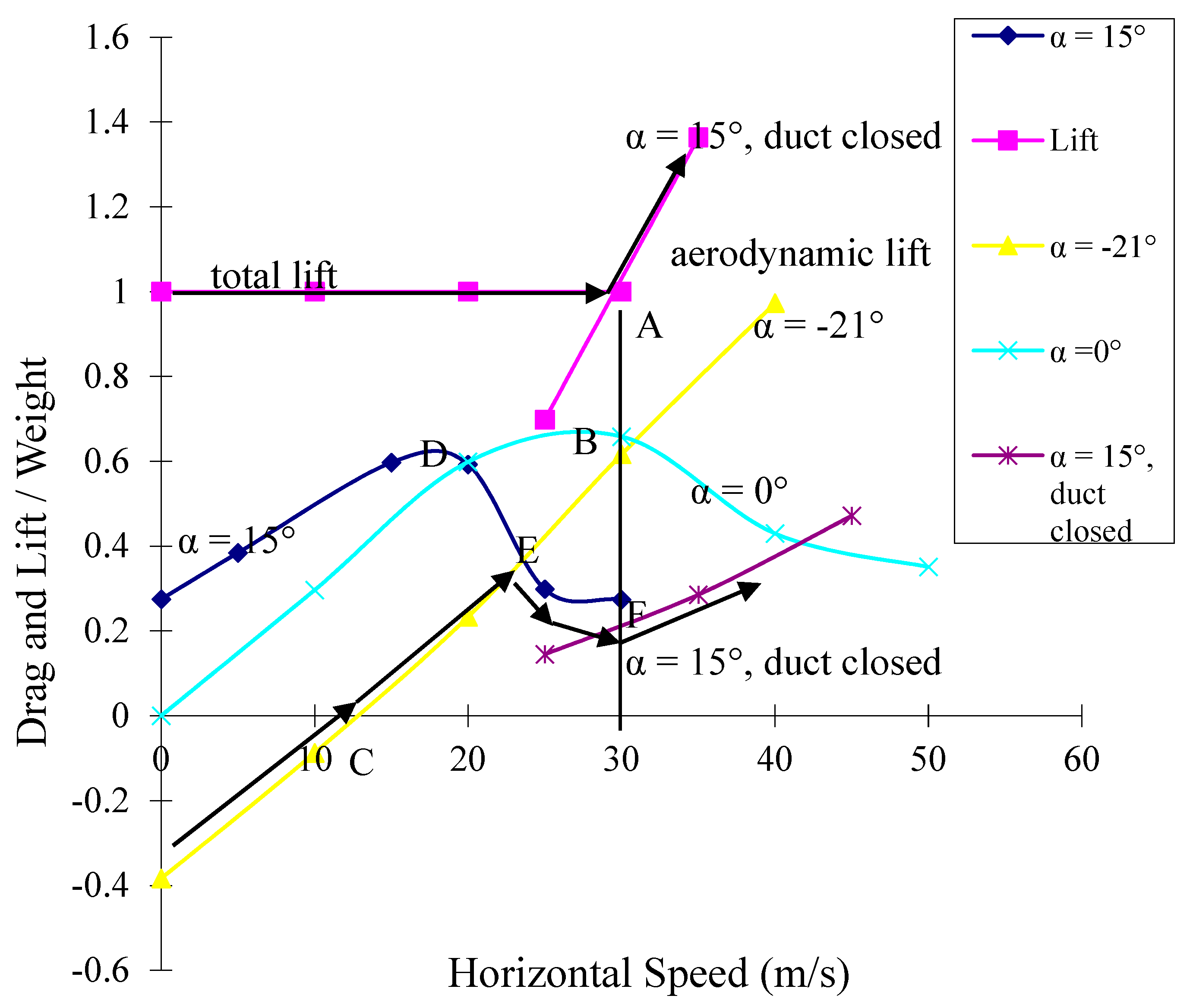
Figure 9, the minimum speed for the aircraft to fly with the duct enclosed on aerodynamic lift is 30 m/s at an angle of attack of 15° (Spot A).
To approach this speed at an angle of attack of zero degrees (
Figure 10a), the momentum drag forms a high peak at Spot B (
Figure 9), which needs a forward jet thrust of 0.63 of the aircraft weight to be overcome. The peak exists because the momentum drag increases with the forward speed and the rotational speeds of the fans, while the rotational speeds of the fans needed to maintain the lift decrease with the forward speed. In the CFD simulation, the rotational speeds of fans were adjusted to keep the lift equal to the weight of the aircraft when the forward speed increased.
Figure 9.
Computed time-averaged net drag and lift-to-aircraft weight ratio at different angles of attack in transition mode. The lift was maintained equal to the weight of the aircraft through the change of the rotational speed of the fans.
Figure 9.
Computed time-averaged net drag and lift-to-aircraft weight ratio at different angles of attack in transition mode. The lift was maintained equal to the weight of the aircraft through the change of the rotational speed of the fans.
In
Figure 9, the drag is not only aerodynamic drag, but net drag, including the horizontal force generated by the lift fan system. If the aircraft flies at a negative angle of attack, as shown in
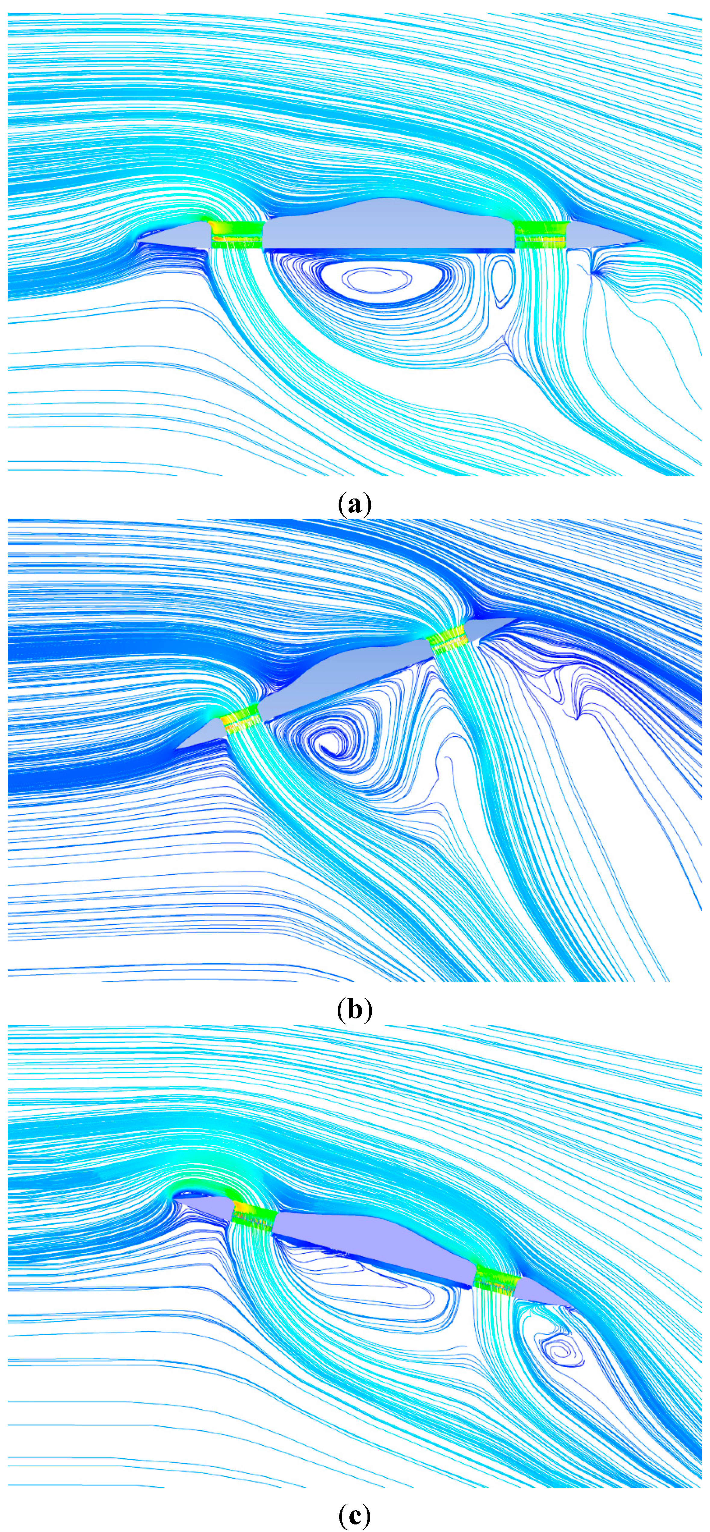
Figure 10b, there is a forward force produced by the lift fan system to offset aerodynamic drag, so the net drag can be negative. When the aircraft starts to fly at a −21° angle of attack (
Figure 10b), the lift fan system generates a forward force to push the aircraft to fly forward without additional forward jet thrust. The aircraft can easily reach the speed of 13 m/s (Spot C) where the net drag is zero, which means that the forward force produced by the lift fan system equals the aerodynamic drag. After that point, the net drag increases rapidly with the increase of speed. The aircraft still needs additional forward thrust of 0.61 of the aircraft weight to reach the speed of 30 m/s.
If the aircraft starts at an angle of attack of 15° (
Figure 10c), the lift fan system will produce a backward force, which is a positive net drag at a speed of 0 m/s. With the increase of the speed, there is also a high peak of drag at the speed of 18 m/s (Spot D), but after that point, the drag decreases rapidly.
Therefore, the best way to achieve efficient transition seems: (1) to rise at an angle of attack of zero degrees; (2) to change the angle of attack to −21° and fly forward without additional forward jet thrust (
Figure 10b); (3) when the speed reaches about 13 m/s (Spot C), continue to fly with additional forward jet thrust; (4) when the speed reaches about 23 m/s (Spot E), change the angle of attack to 15° (
Figure 10c), slow down the rotational speeds of the fans and continue to fly with additional forward jet thrust until the speed reaches 30 m/s (Spot F); (5) to stop the lift fan system and close off the duct; and (6) to continue to fly with aerodynamic lift and forward jet thrust. In this way, the peak of momentum drag is much lower (near Spot E), which only needs forward thrust of about 0.32 of the aircraft weight to overcome. The lift and net drag increase along the arrows in
Figure 9.
Figure 10.
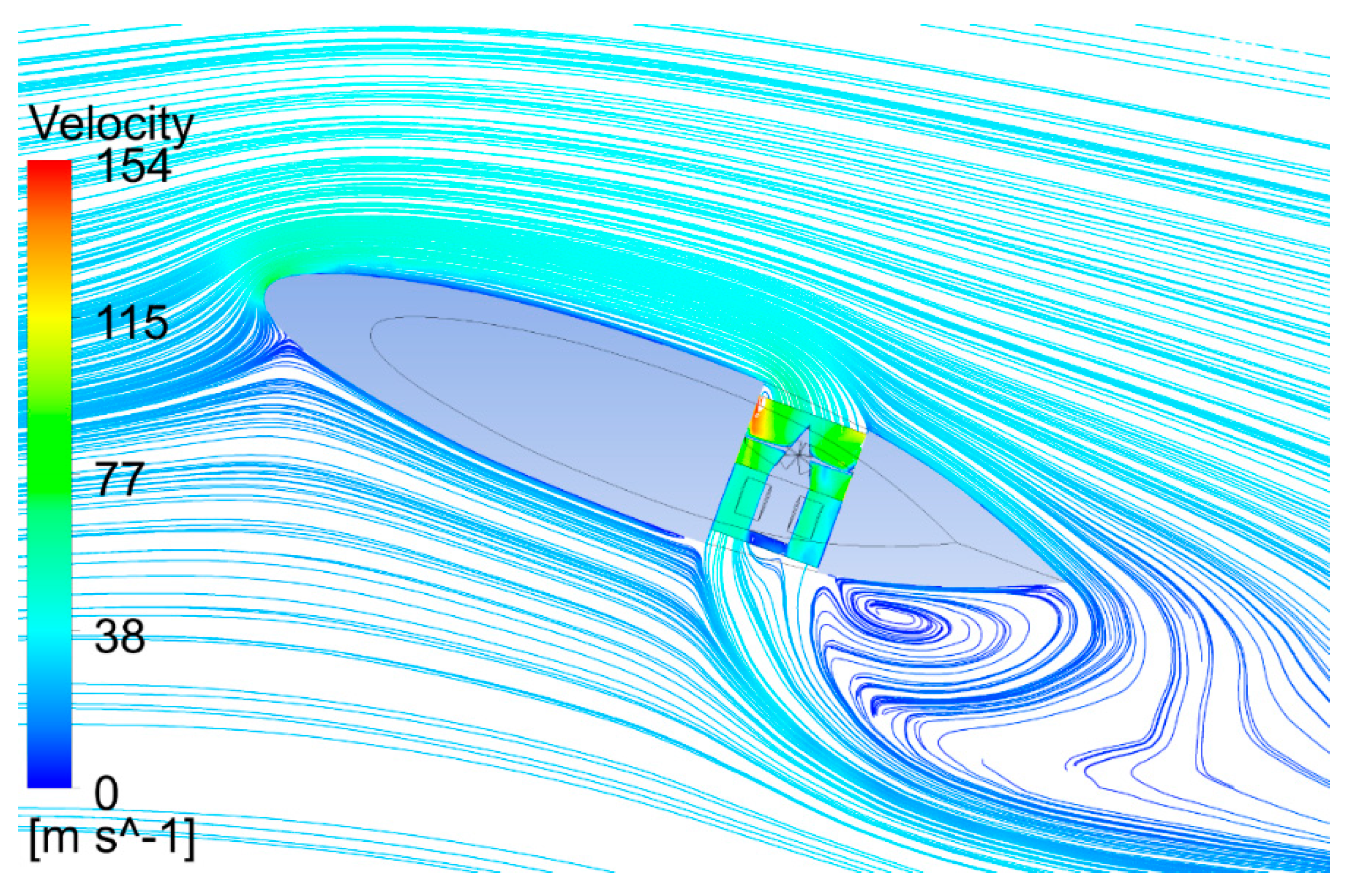
The aircraft attitudes and streamlines in the central plane of the aircraft in transition mode. The lift was maintained equal to the weight of the aircraft by adjusting the fan rotational speeds. (a) Angle of attack α = 0°, freestream speed U = 20 m/s, fan speeds N = +108, −117 rpm; (b) angle of attack α = −21°, U = 10 m/s, fan speeds N = +122, −121 rpm; (c) angle of attack α = 15°, U = 20 m/s, fan speeds N = +91, −97 rpm.
For vertical landing, the aircraft can start to reduce the forward speed at an angle of attack of 15°, then open the duct and start the lift fan system (
Figure 10c). When the forward speed slows down, then change the angle of attack to zero degrees to land (
Figure 10a).
The aircraft attitudes and the streamlines in the central plane in transition mode are presented in
Figure 10a–c. The incoming flow on the aircraft’s upper side is strongly entrained by the lift fan system, maintaining attached flow at the aircraft’s trailing edge.
The attitude control can be performed through changing the direction of the thrust from the two jet engines respectively. Thrust vectoring can also be used to offset the nose up pitching moment and rolling moment during the transition.
6.3. Aerodynamic Drag and Horizontal Cruise Speed Predictions
During cruise flight, the annular-ducted fan lift system will be shut off to reduce drag and provide aerodynamic lift, so the compressibility effects on the fan blade tips and fan drag will be eliminated and replaced by aerodynamic drag. With the lift fan system enclosed during horizontal flight, the aerodynamic drag of a specific size may be smaller than the rotor drag, so the aircraft may possibly fly faster than helicopters and tiltrotors.
The drag and lift of the aircraft with the annular duct system enclosed during level flight were simulated. As shown in
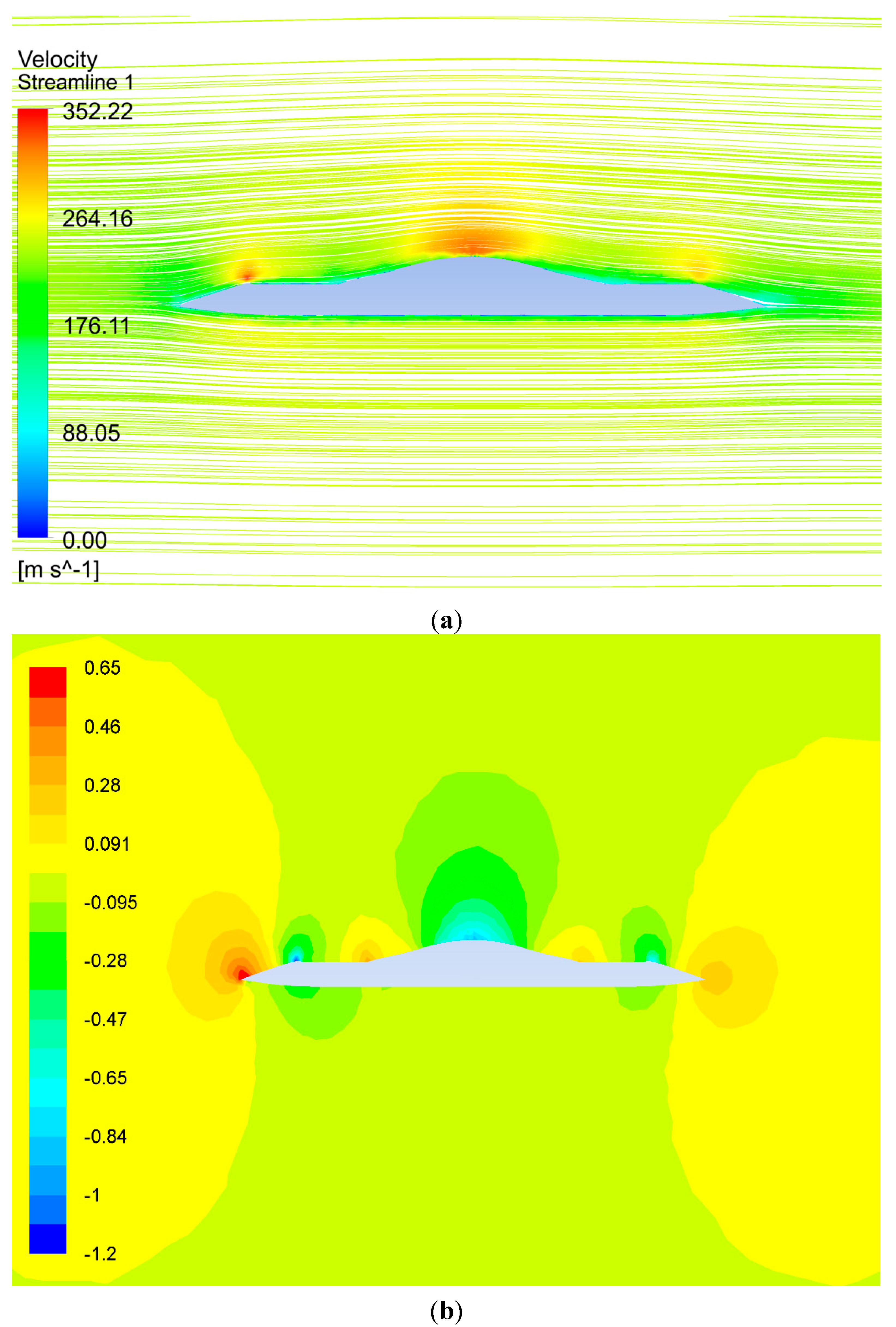
Figure 11, the airflow speed on the cambered upper surface of the aircraft increases (
Figure 11a) and causes low pressure to generate lift (
Figure 11b). The aerodynamic drag increases with flight speed (
Figure 12).
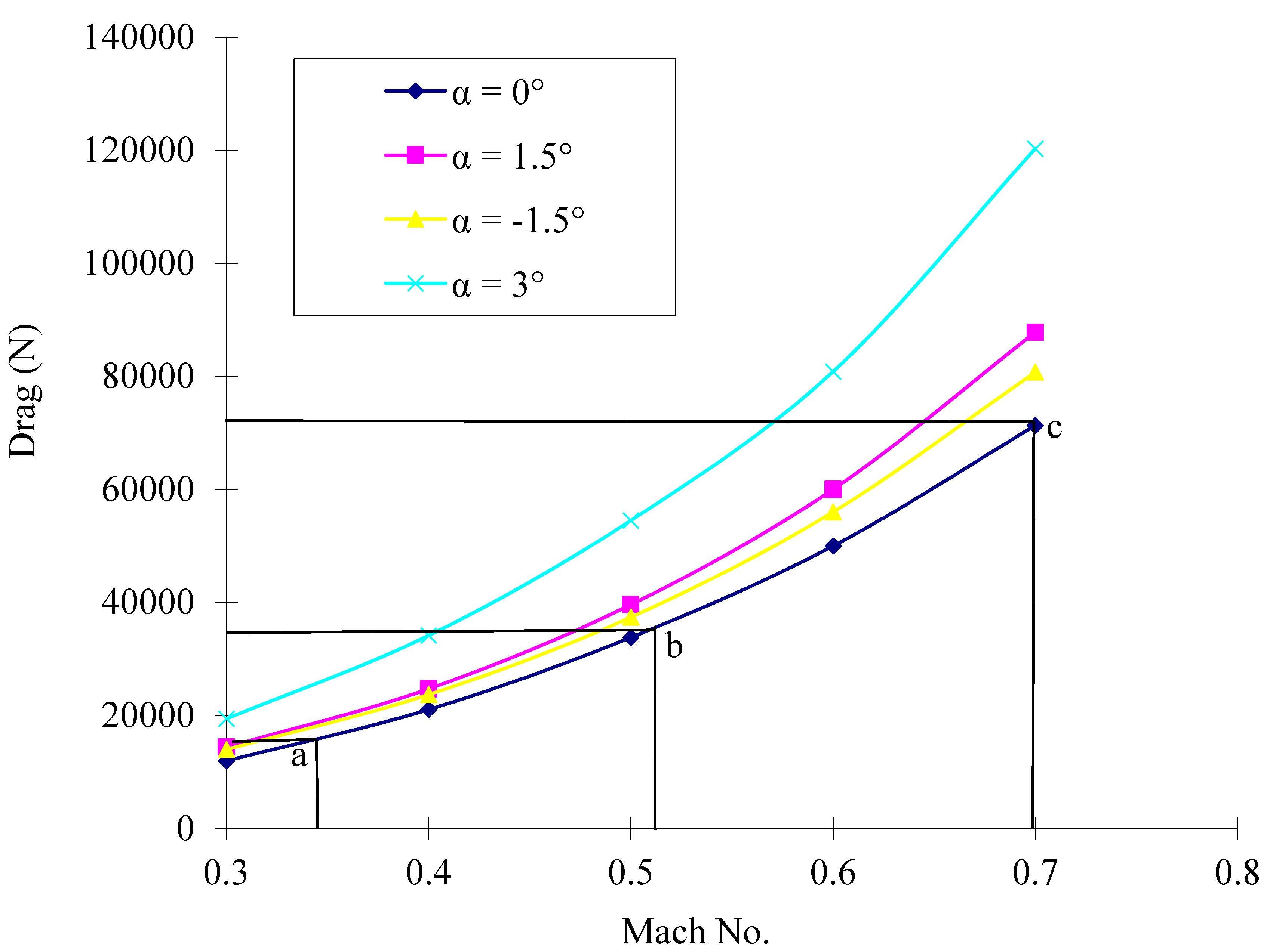
Based on the balance of drag and jet thrust, when the drag equals the engine thrust, the maximum speed of the aircraft can be predicted. Therefore, when the flight speed increases to 0.35 Ma (428 km/h) at a zero degree angle of attack (
Figure 12, Spot a), the drag is 15.7 kN. If the maximum jet thrust is just 15.7 kN, the maximum speed will be 428 km/h. Supposing the propulsive efficiency is 0.7, the jet power at this point is 2676 kW, which is the power of the Apache. While the maximum speed of the Apache is 293 km/h, the speed of 428 km/h is 46% faster than the Apache. At this point, the lift is 131 kN, enough to carry a weight of 102 kN. The configuration of the aircraft can be slightly modified (not so cambered) to reduce the lift to equal the weight without increasing the drag, so that the aircraft can fly in the minimum drag mode. The maximum speed is predicted here only based on drag prediction; some real-world effects, including engines, were not considered. The prediction of drag just gives some ideas about how fast the aircraft may theoretically fly without rotor drag.
If the jet thrust increases to 36.3 kN, the maximum speed will reach 0.52 Ma (625 km/h;
Figure 12, Spot b). Supposing that the propulsive efficiency is 0.7, the jet engine power at this point is 9180 kW, which equals the power of the V-22 Osprey. The maximum speed of the Osprey is 509 km/h.
Without the constraints of rotor drag and the compressibility effects on the rotor blade tips, the speed of the aircraft can increase further if higher thrust turbofan jet engines are deployed. To reach the speed of 0.7 Ma (857 km/h), the aircraft will need jet thrust of 72.3 kN (
Figure 12, Spot c). The lift at this point is 448 kN, much higher than the weight.
Figure 11.
(a) Streamlines in the central plane of the aircraft in cruise mode; (b) pressure coefficient in the central plane of the aircraft at speed of 0.7 Ma.
Figure 11.
(a) Streamlines in the central plane of the aircraft in cruise mode; (b) pressure coefficient in the central plane of the aircraft at speed of 0.7 Ma.
Figure 12.
The computed drag (the engines were not considered) of the aircraft increases with cruise speed at different angles of attack.
Figure 12.
The computed drag (the engines were not considered) of the aircraft increases with cruise speed at different angles of attack.
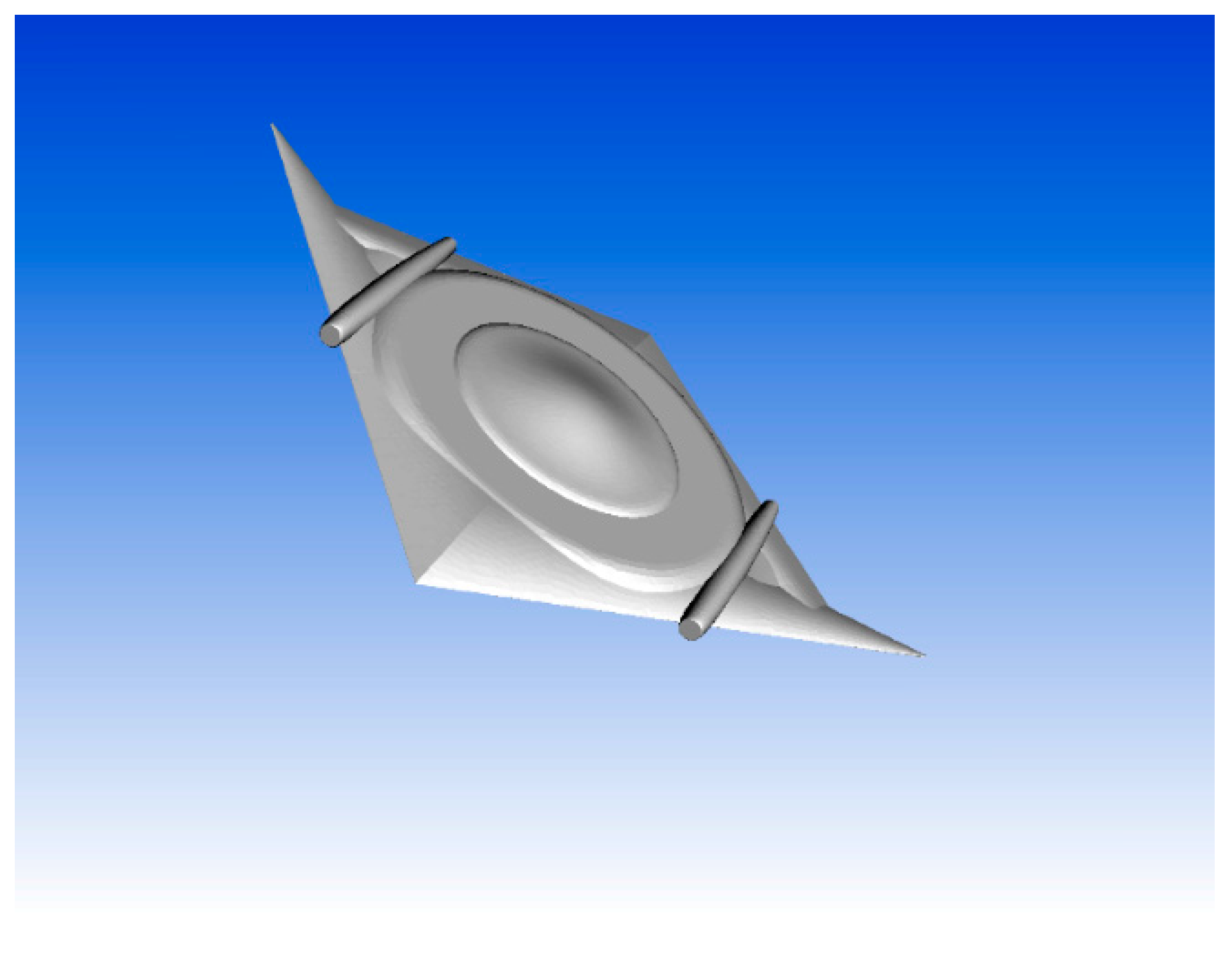
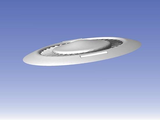
The annular-ducted lift fan aircraft can also be in other configurations, rather than the above circular flying saucer shape, to reduce drag. A triangular or rhombic configuration (
Figure 13), like a blended wing body [
21,
22], may fly faster and is easier to deploy conventional aerodynamic control surfaces. Aerodynamic drag is determined by the shape and size of the aircraft. A thinner and streamlined shape has less drag and thus may fly faster.
Figure 13.
Rhombic-shaped annular-ducted lift fan aircraft.
Figure 13.
Rhombic-shaped annular-ducted lift fan aircraft.
6.4. Pneumatic Coupling of Tip Turbine and Engine Exhaust Gases
Shaft-driven and gas-driven annular-ducted lift fan systems are both feasible. The F-35 joint strike fighter finally adopted a shaft-driven lift fan [
1], but a gas-driven annular-ducted lift fan system may be less expensive to develop than the shaft-driven system, because it does not require modifying the cruise engine. There are no gears or high power shafting required, and pneumatic coupling also provides balanced engine operation and engine out safety [
2]. A preliminary gas-driven tip turbine CFD study was performed without validation due to a lack of experimental data.
As shown in
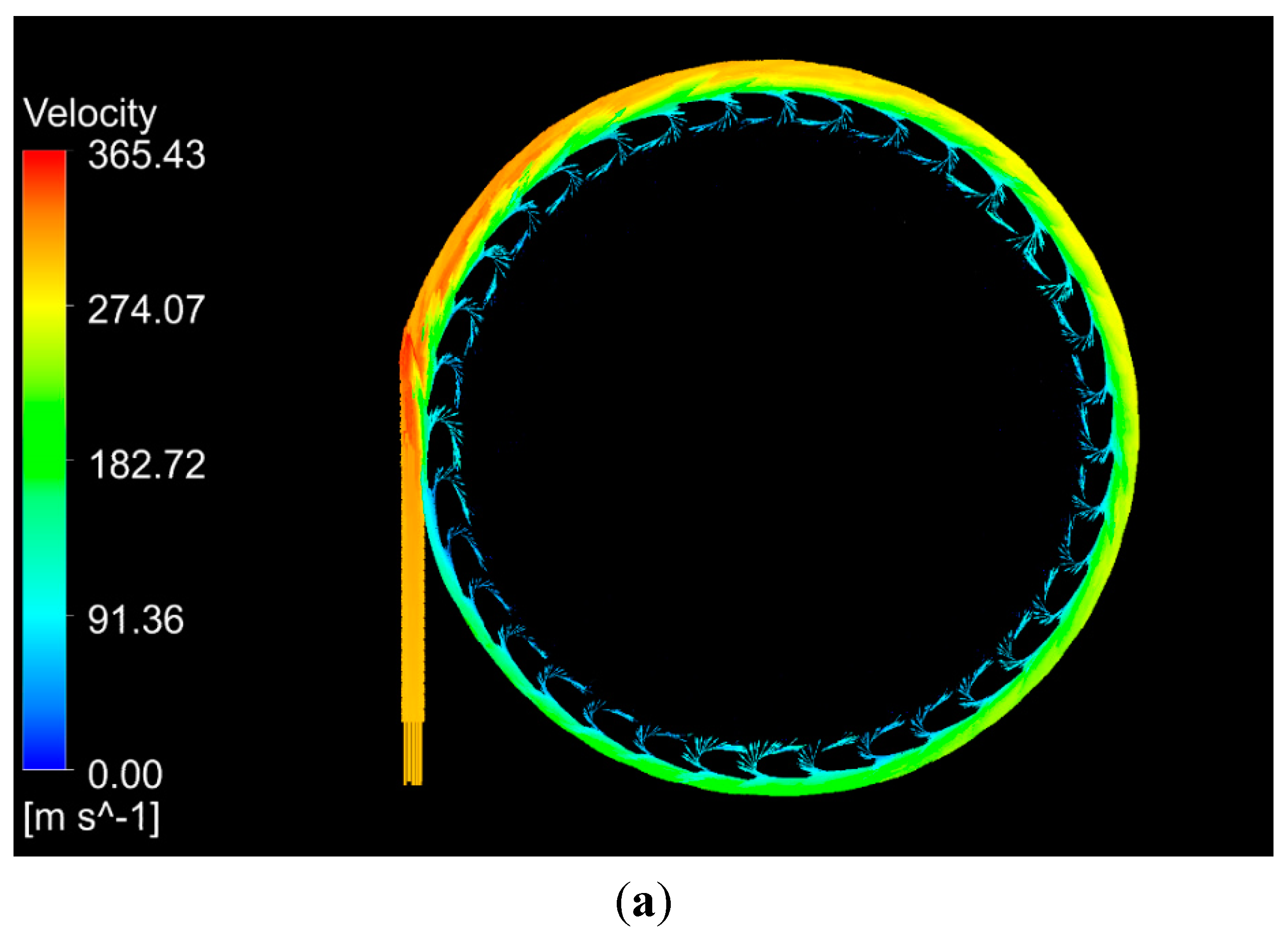
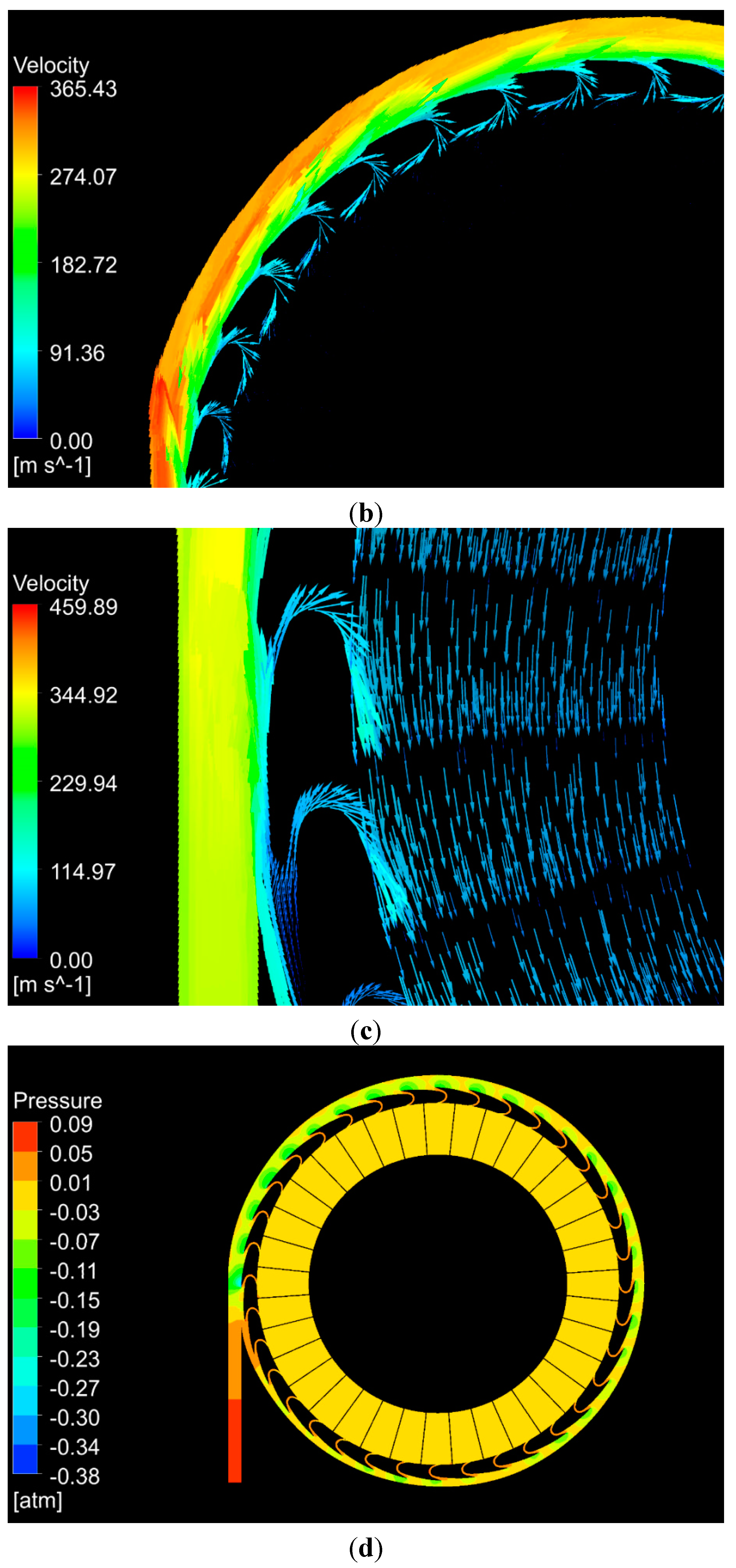
Figure 14, the engine exhaust gases are ducted to the inlet of the gas chamber to spin the tip turbine. With a velocity inlet speed 300 m/s, a significant flow forms in the chamber (
Figure 14a,b). The gas flow starts from the inlet, circulates in the chamber, passes through the turbine blades, exits from the outlets on the chamber and discharges itself to the annular duct. When the turbine and lift fan begin to rotate, the exiting gases mix with the rotating air (
Figure 14c). The gas flows passing through the tip turbine blades cause a pressure difference on the two surfaces of a turbine blade (
Figure 14d,e), which pushes the turbine to spin. A steady solution could not be achieved due to the strong unsteadiness on the turbine blade loading. Unsteady analysis showed that the forces on the blades slightly fluctuated with time, and time-averaged results could be obtained. With an inlet speed 300 m/s, when the turbine is still, the average moment of the gas flows on the turbine blades is about 156 kN m. When the turbine rotates at 120 rpm, the moment on the turbine blades is about 108 kN m, greater than the contra-moment on the lift fan of 100.6 kN m (see
Section 6.1), thus enough to maintain the rotation of the lift fan. The gauge pressure inside the chamber is as low as about 0.1 atm (
Figure 14d), making it easy to couple with the jet exhaust.
According to the lift fan experimental results with a fan diameter of 1.5 m, the fan augments the turbojet thrust by a factor of three to one for VTOL [
2]. With the fan size increased to a diameter of 14 m, the fan may possibly augment jet thrust by more than five-fold.
Figure 14.
(a) Velocity vector in the central plane of the gas chamber when the tip turbine was still; (b) enlarged view of velocity vectors; (c) enlarged view of velocity vectors when the tip turbine rotated at a speed n = 120 rpm; (d) pressure contour in the central plane of the chamber; (e) the enlarged view of pressure on the turbine blades to show the pressure difference on two sides of the blades.
