1. Introduction
The presence of morphing technology in the aircraft design has allowed the aircraft to change its shape. The shape variation that an aircraft can produce helps the aircraft to attain a better performance and efficiency in a wider range of flight mission [
1]. In other words, the morphing aircraft has the capability to perform an optimized aerodynamic performance in other flight missions rather than a specific flight mission. As a result, many researchers have attempted to develop some morphing techniques in order to get a better aircraft performance and efficiency.
The idea of shape changing in the wings of an aircraft was started by the Wright Brothers. At that time, they developed a camber and twist variation on the wing shape [
2]. In the recent decades, many new concepts of morphing have been applied as well. In their work, Barbarino
et al. [
3] have made a chronological summary about the application of morphing concept on the fixed wing started from 1903 to 2010.
These morphing concepts can be classified into three different criteria in terms of shape variation: planform morphing (includes the variation span, sweep, and chord of the wing), out-of-plane morphing (includes the variation in twist, dihedral, and span-wise bending), and airfoil adjustment morphing (concerns of thickness and camber of the airfoil section) [
3].
The morphing technology has some major drawbacks in the application. One major drawback is that a morphing wing often requires complex mechanisms which increase the installation and maintenance costs [
4]. Another major issue is the additional weight that the complex mechanisms bring. Furthermore, the structural analysis and design of morphing wings are also more complicated due to these issues. Consequently, conventional sizing approach also becomes insufficient and requires far more complicated methods.
Regarding the design of a camber variable wing, Shilli
et al. [
5] categorized three different methods to perform it: the conventional hinged mechanism, the smart-material-made actuators, and the compliant mechanism. Despite the easy integration and simple actuation that conventional control surface has, this system also have some major drawbacks. The existing discontinuities produced by the conventional control surfaces may result in flow separation and increase in drag [
3]. Conversely, the unconventional control surfaces with the smart-material-made actuators and the compliant mechanisms can provide smooth shape changes along the wing surface, hence, can decrease the adverse effects of the conventional ones.
There have been many research studies concerning adaptive trailing edge control surfaces. Smart Wing Program, which was funded by Defense Advanced Research Program Agency (DARPA) is one of them. A trailing edge control surface composed of elastomeric (silicone) outer skin, flexible honeycomb and fiberglass laminate as a center leaf is one of the concepts developed under this program. While the honeycomb part is responsible for increasing the resistance to vertical loads, the silicone skin which undergoes large deformations provides a smooth shape change and reduces the actuation forces in this concept. Additionally, the chordwise shape of the control surface is stabilized by the laminate part [
6].
Within the context of morphing trailing edge development, the German Aerospace Center (DLR) investigates two different concepts for the camber variation. The first concept is the finger concept trailing edge design, having a metallic flexible skin whose aim is to achieve a smooth aerodynamic profile. The ribs of the concept are modelled by combining separate plate-like elements (fingers) with revolute joints [
7]. A transmission beam, which groups the ribs, is designed in order to reduce the number of actuators to be utilized. Consequently, the trailing edge control surface with finger concept deforms into an arc-like shape [
8]. The second design of the DLR is the belt rib control surface concept where the skin is modelled like a belt and the ribs are designed like spokes. The desired camber variation shape change of the trailing edge control surface is achieved by altering the angle of the spokes, which connect the upper and lower parts of the belt [
9]. More information about the morphing control surfaces can be found in the author’s thesis work [
10].
In this paper, the idea of a novel camber morphing mechanism is introduced for the trailing edge of an unmanned aerial vehicle wing. In the developed concept the gap, which exists between the wing and the control surface in conventional designs, is eliminated, thereby a smooth flow over the wing-box and the trailing edge is provided. This hybrid trailing edge control surface was developed within the scope of CHANGE (Combined morphing assessment software using flight envelope data and mission based morphing prototype wing development) Project financed under the 7th Framework Program of the European Commission [
11].
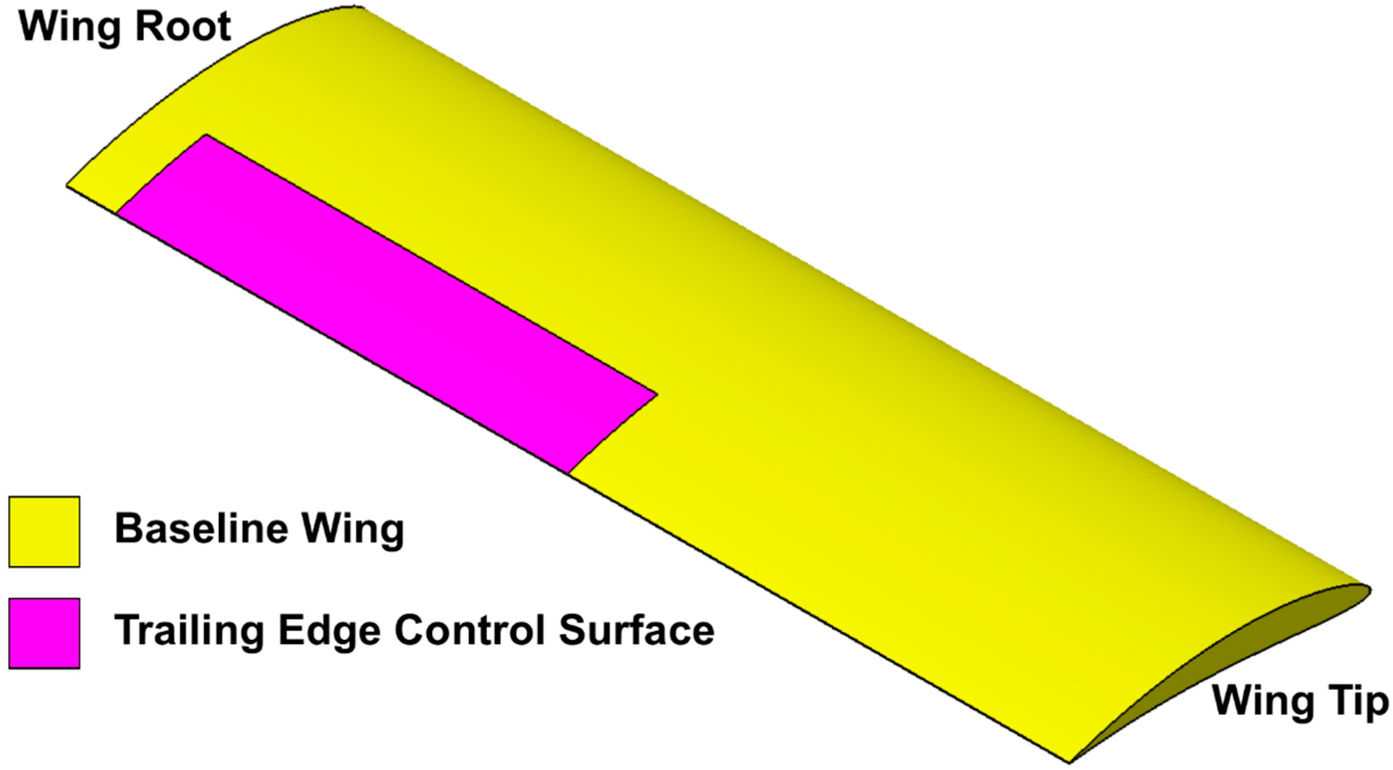
The baseline unmanned aerial vehicle wing has a NACA 6510 cross section with half span equals to 2 m and no pre-twist along the wing span. The control surface started 10 cm from the root of the baseline wing.
Figure 1 depicts the geometry of the half span wing and the location of the control surface.
Figure 1.
Baseline wing geometry.
Figure 1.
Baseline wing geometry.
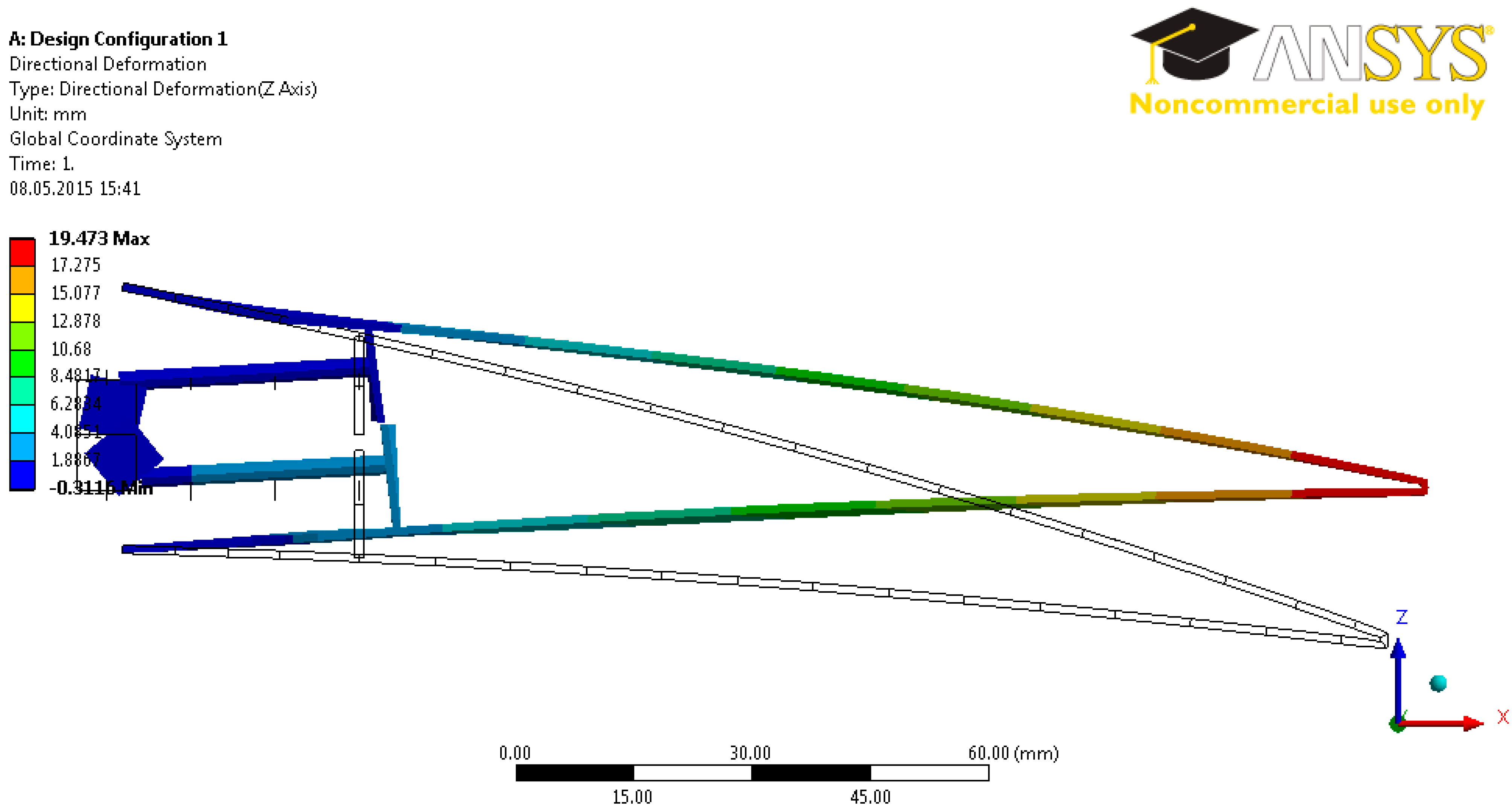
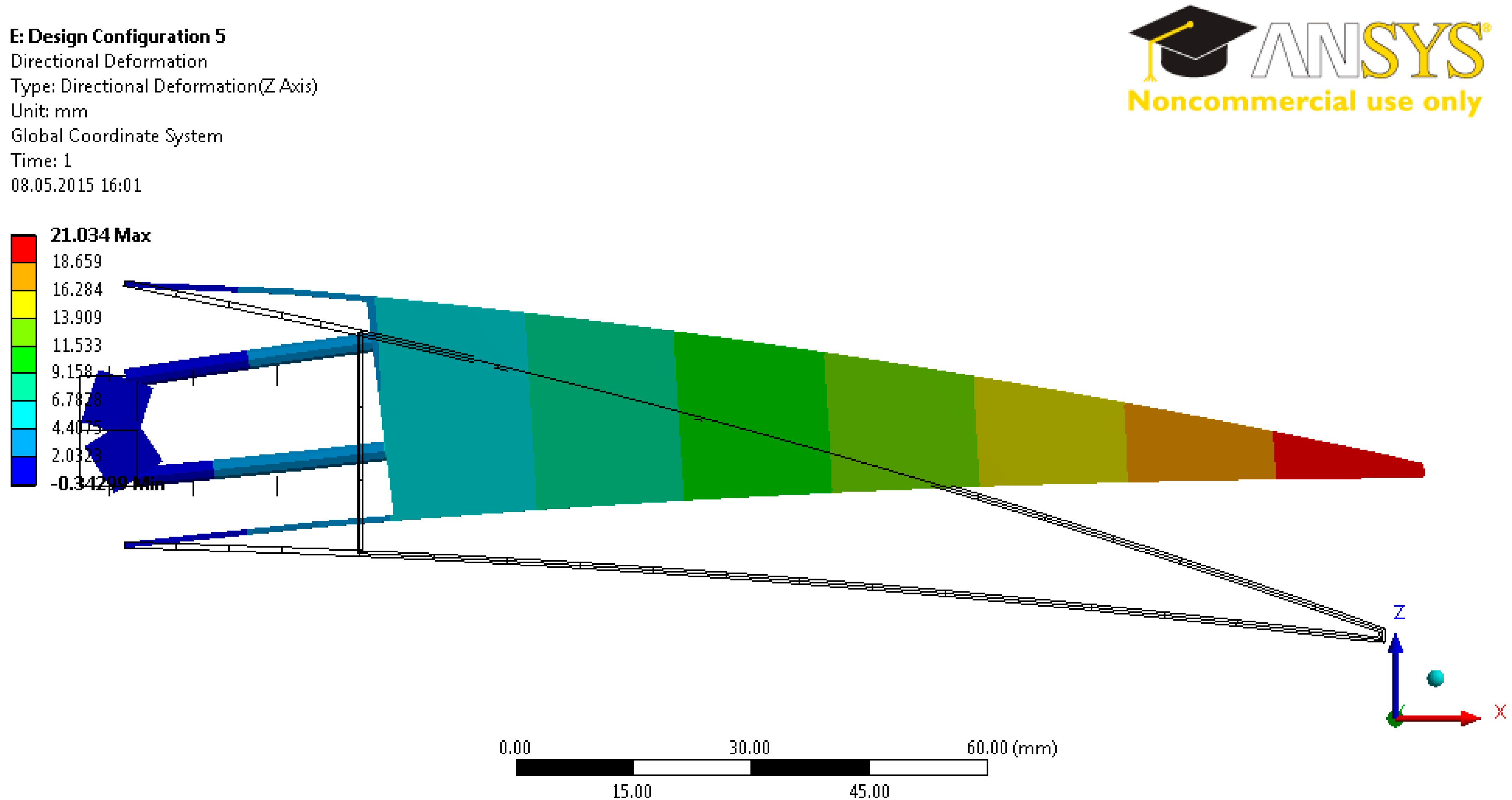
The main purpose of the structural design was to achieve a minimum torque for the required morphing value. Hence, several structural design configurations have been tried. The differences between the configurations comprise the properties of the material used in the design, and the number and location of the servo actuators used in the design.
This paper first gives the structural design followed by the details of the Finite Element Analysis (FEA) used in the design process. The comparative studies were conducted in vacuo in order to get an optimum design is then elaborated. Computational Fluid Dynamics (CFD) analysis done in order to get the aerodynamic loads is followed by the analyses of the control surface under the simulated aerodynamic loading.
2. Structural Design
The structural design of the morphing trailing edge concept is explained in this section. It is mainly focused on the description of the design; the materials, the number and location of the servo actuators used in the design. The effects of variation of these variables on the design are considered during the design trade-off studies.
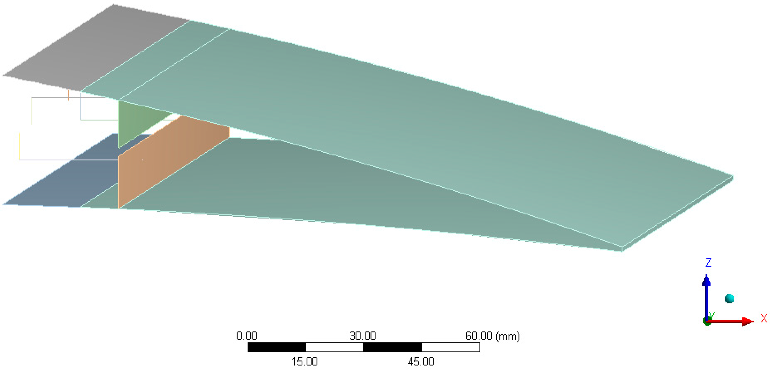
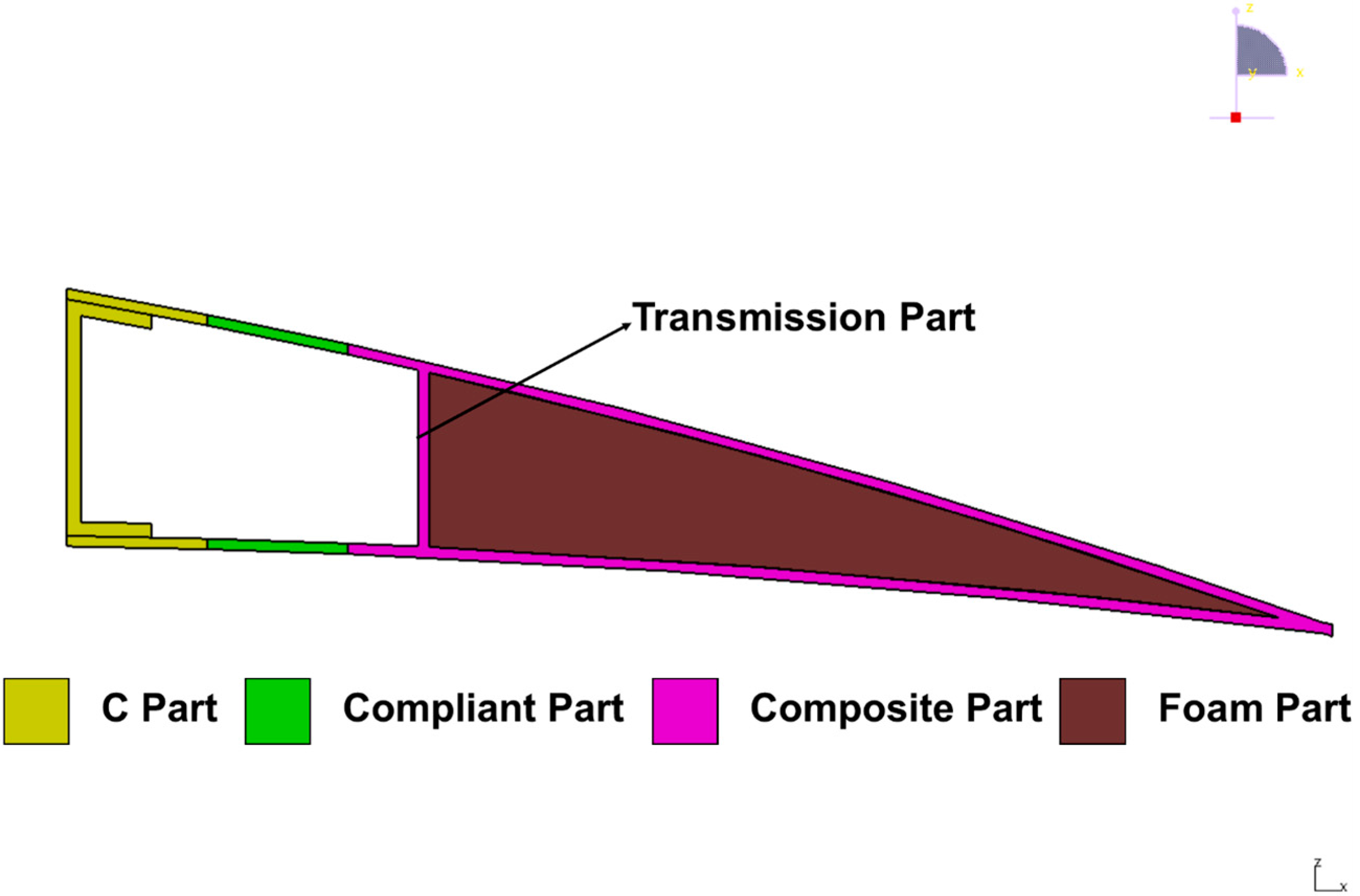
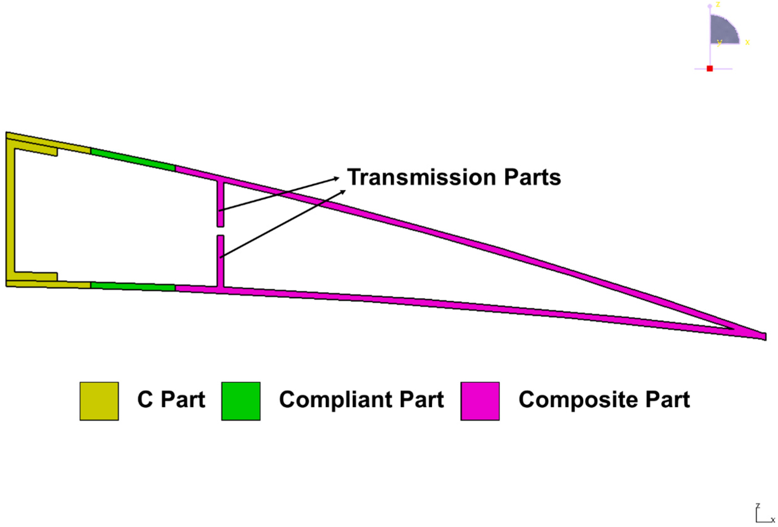
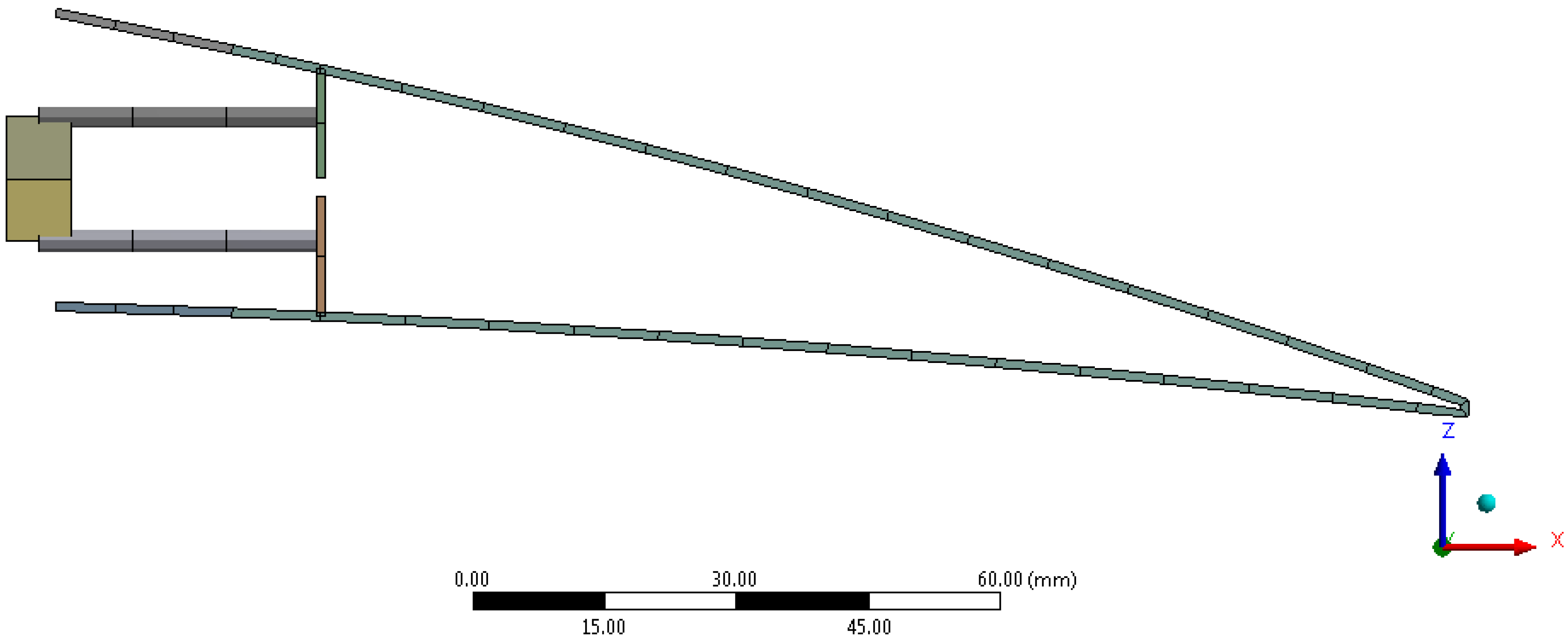
In the study two different design concepts were undertaken. The difference was based on the section called the “transmission part” which is the part used to transfer the forces from the servo actuators to the control surface. When there are two separate transmission parts the concept is called the open cell design and when there exists only a single transmission part it is called the closed cell design. Both of the proposed designs have three common components as the C-Part, the compliant part and the composite part. The details of both open cell and closed cell designs are shown in
Figure 2 and
Figure 3, respectively.
Figure 2.
Hybrid trailing edge open cell control surface design.
Figure 2.
Hybrid trailing edge open cell control surface design.
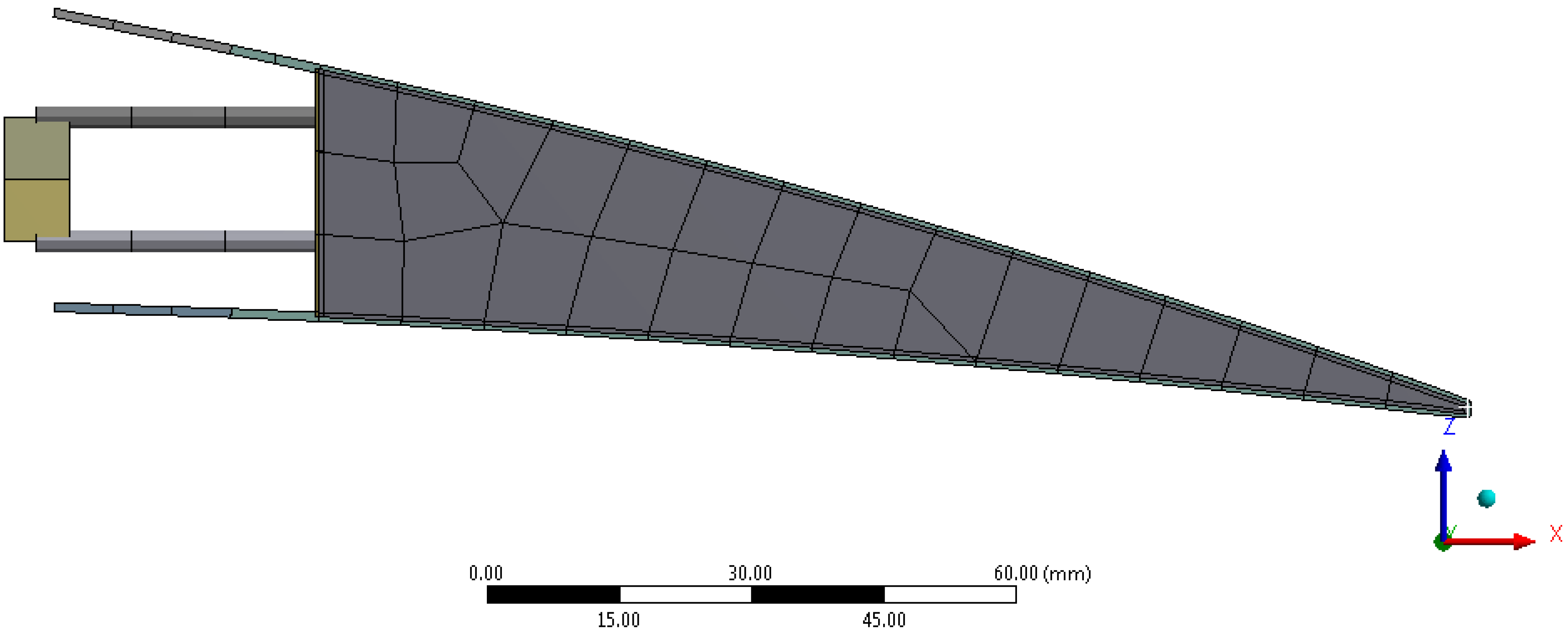
Figure 3.
Hybrid trailing edge closed cell control surface design.
Figure 3.
Hybrid trailing edge closed cell control surface design.
During the closed-cell design a foam material is placed inside the available volume in the composite part in order to increase the transverse stiffness of the control surface under aerodynamic loads. The presence of the foam material inside the control surface itself is illustrated in
Figure 3. The Rohacell
® 51 RIMA [
12] was used as the foam material and the properties of this material is given in
Table 1.
Table 1.
Material properties of Rohacell
® 51 RIMA foam [
12].
Table 1.
Material properties of Rohacell® 51 RIMA foam [12].
| Properties | Values |
|---|
| Density, ρ | 52 kg/m3 |
| Young’s Modulus, E | 75 MPa |
| Shear Modulus, G | 24 MPa |
The C-Part component was used as the connection part, which connects the control surface to the wing. The material used for C-Part is aluminum and
Table 2 provides information concerning the material properties.
Table 2.
Material properties of the aluminum used in the C-Part [
13].
Table 2.
Material properties of the aluminum used in the C-Part [13].
| Properties | Values |
|---|
| Density, ρ | 2770 kg/m3 |
| Young’s Modulus, E | 71 GPa |
| Poisson’s Ratio, ν | 0.33 |
| Tensile Yield Strength | 280 MPa |
| Tensile Ultimate Strength | 310 MPa |
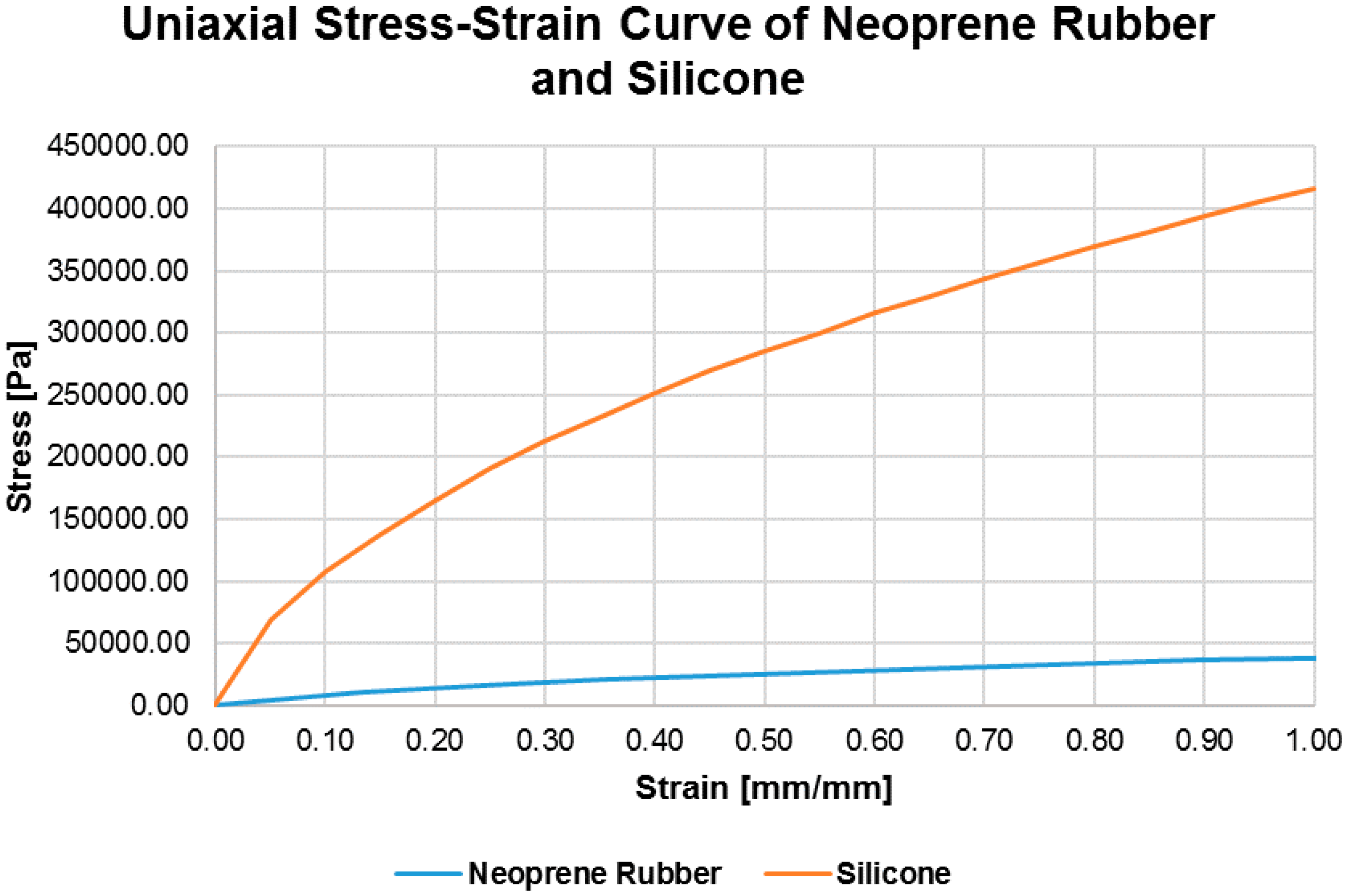
The compliant part was made by a very flexible material in such a way that it can undergo a significant amount of deformation. The main principle implemented in the control surface is to have tension in both upper and lower compliant parts during the actuation. This is necessary in order to avoid any possible slack in the compliant part which could easily occur in the case where the compliant part was subjected to compression. Then, the difference in the elongations of both compliant parts will give rise to required decamber behavior.
During the study two different materials were proposed for the compliant part: neoprene rubber and a silicone-based material. The density of neoprene rubber is used as 1250 kg/m
3 [
14].
Another material used for the compliant part is a silicone based material provided by INVENT GmbH [
15]. A uniaxial tension test was conducted in Middle East Technical University, Department of Aerospace Engineering, in order to obtain the stress-strain curve of the material. The density of the silicone-based material was taken as 1250 kg/m
3 [
14]. The uniaxial stress-strain curves of neoprene rubber and the silicone are shown in
Figure 4.
The composite part is made of glass-fiber prepreg EHG250-68-37 [
15], which is significantly stiffer as compared to the compliant part of the control surface. Due to this fact when there are in plane deflections in the upper and lower compliant parts the composite part deflects as if it is undergoing a rigid body rotation. The properties of the composite used in the rigid part are given in
Table 3.
Figure 4.
The uniaxial stress-strain curves of neoprene rubber [
13] and silicone.
Figure 4.
The uniaxial stress-strain curves of neoprene rubber [
13] and silicone.
Table 3.
Material properties of glass-fiber prepreg EHG250-68-37 composite [
14].
Table 3.
Material properties of glass-fiber prepreg EHG250-68-37 composite [14].
| Properties | Values |
|---|
| Density, ρ | 1900 kg/m3 |
| Young’s Modulus, E11 | 24.5 GPa |
| Young’s Modulus, E22 | 23.8 GPa |
| Poisson’s Ratio, ν12 | 0.11 |
| Shear Modulus, G12 | 4.7 GPa |
| Shear Modulus, G13 | 3.6 GPa |
| Shear Modulus, G23 | 2.6 GPa |
| Ply Thickness | 0.25 mm |
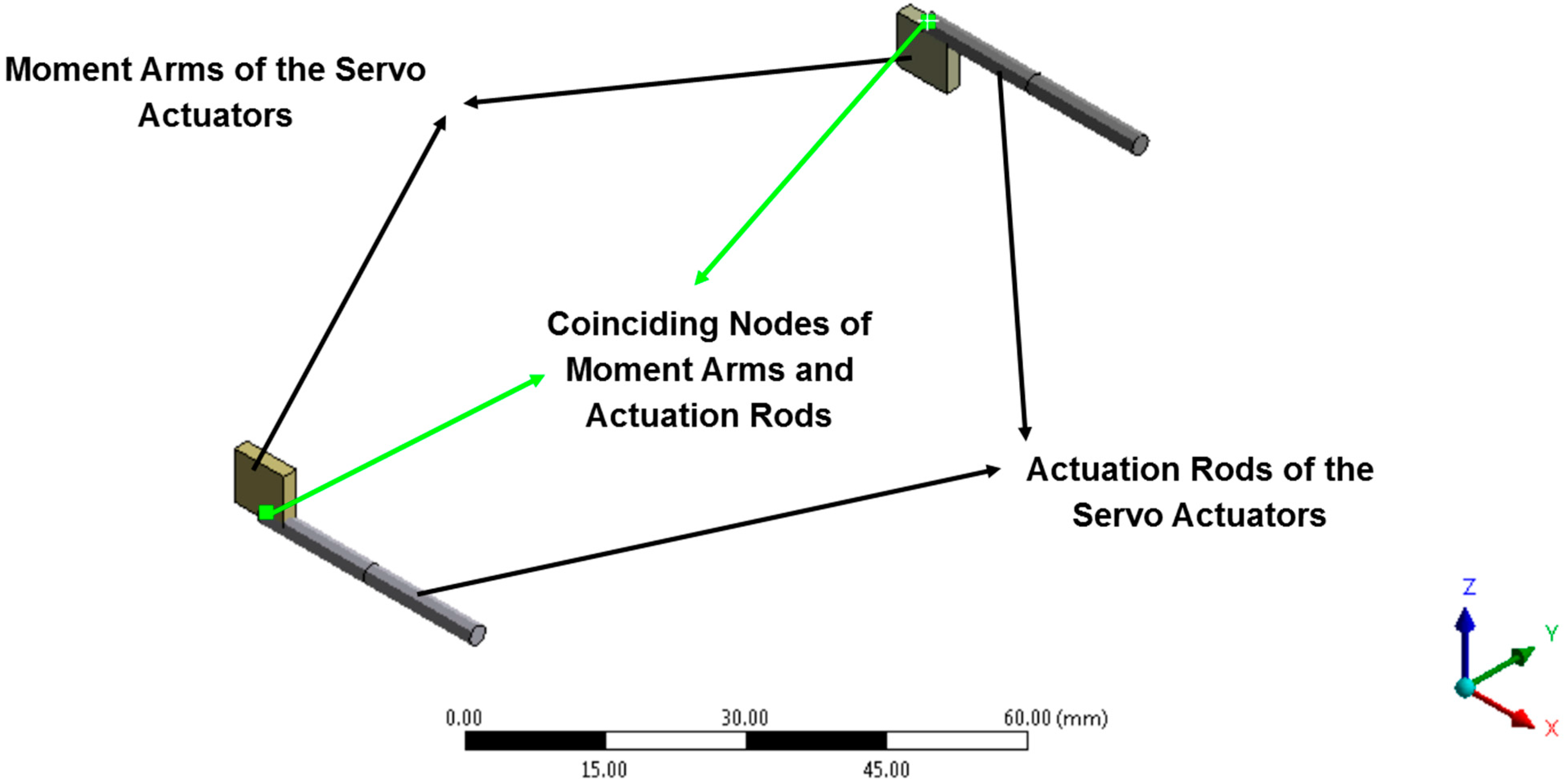
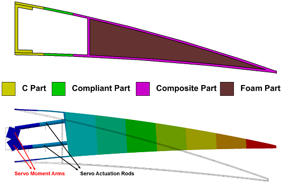
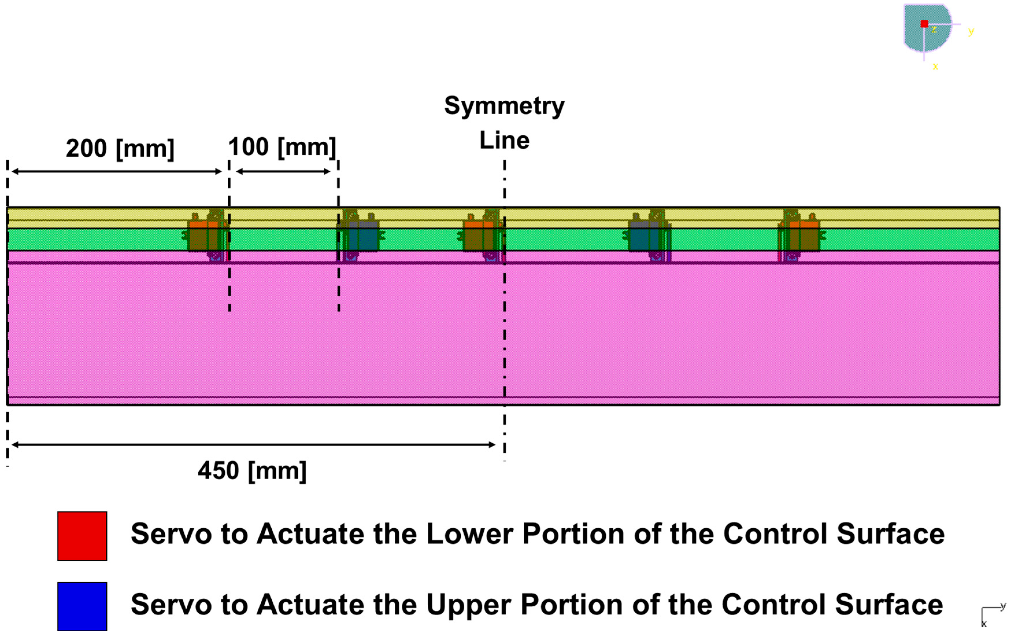
The Servo Actuators
The main actuation mechanism used in the developed morphing concept was the servo actuator. There were two approaches analyzed in this study. In the first one, two servo actuators were used to actuate the upper part of the control surface and another two servo actuators were utilized in order to actuate the lower part of the control surface. In the second one, a total of five servo actuators were utilized. In that configuration two servo actuators actuate the upper part of the control surface and three servo actuators utilized for the actuation of the lower part of the control surface. Hence, both the numbers and the locations of the servo actuators were studied and their effects on the design were evaluated.
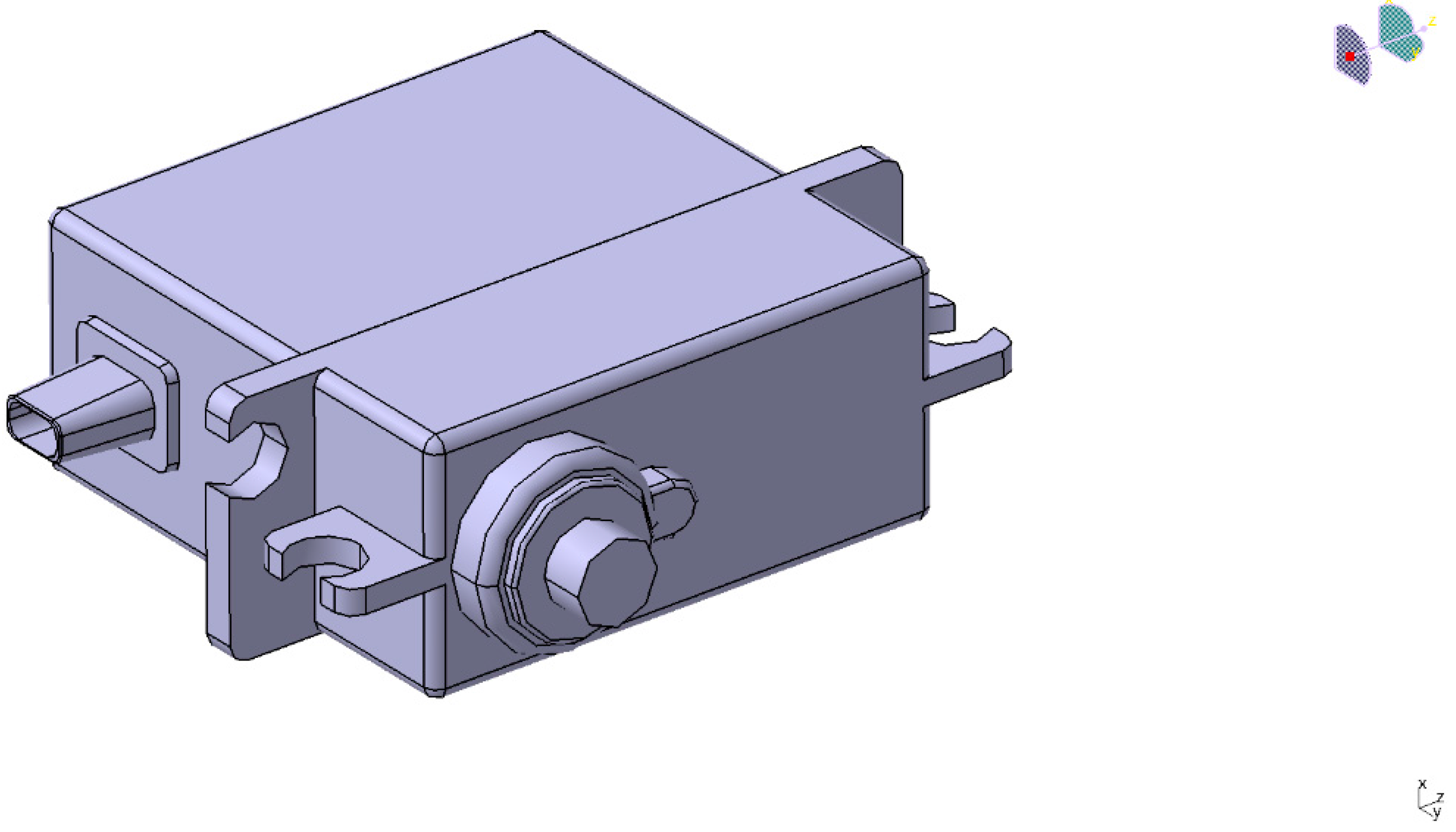
Since the servo actuators were placed within the trailing edge control surface, very small sized servo actuators were used in the design due to the very restricted available space. Considering the available torque that servos can provide; it has been determined that Volz DA 13-05-60 servo actuator whose can meet the requirements. The CAD model of the servo actuator is shown in
Figure 5 and specifications are given in
Table 4.
Figure 5.
CAD model of Volz DA 13-05-60 servo actuator [
16].
Figure 5.
CAD model of Volz DA 13-05-60 servo actuator [
16].
Table 4.
The specifications of Volz DA 13-05-60 servo actuator [
16].
Table 4.
The specifications of Volz DA 13-05-60 servo actuator [16].
| Parameters | Values |
|---|
| Operating Voltage | 5 V |
| Peak-Torque | 600 N-mm |
| Weight | 19 g |
| Dimensions | 28.5 mm × 28.5 mm × 13 mm |
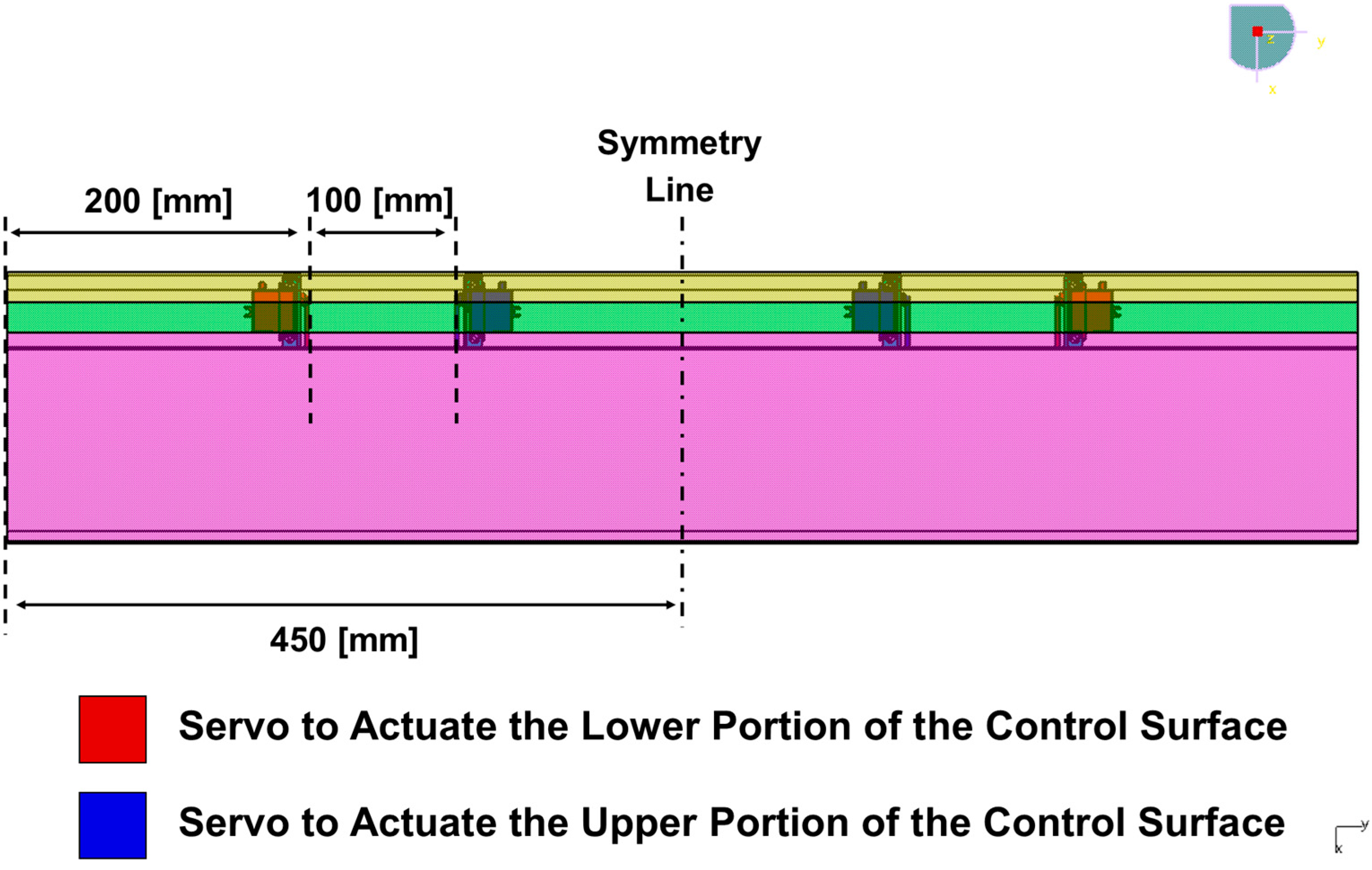
Figure 6 and
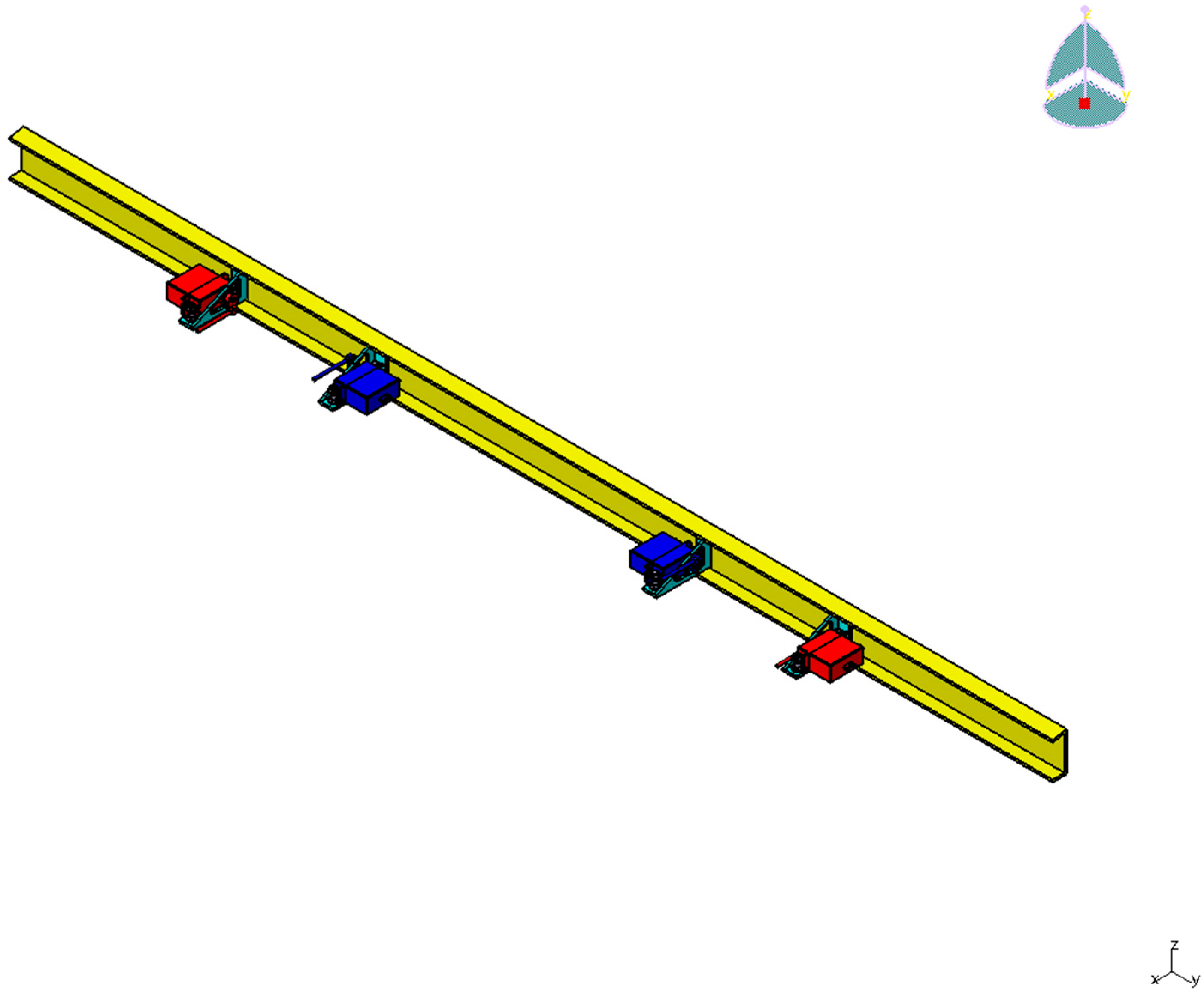
Figure 7 illustrate the top and isometric view of the configuration for four servo actuators, respectively. On the other hand,
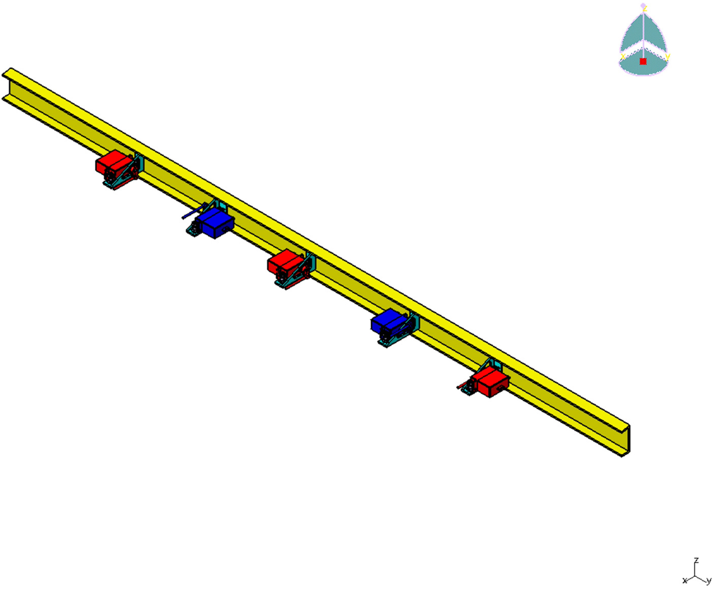
Figure 8 and
Figure 9 show the top view and isometric view of the configuration for five servo actuators, respectively.
Figure 6.
Top view of servo actuators in a four servo actuator configuration.
Figure 6.
Top view of servo actuators in a four servo actuator configuration.
Figure 7.
Isometric view of servo actuators in a four servo actuator configuration.
Figure 7.
Isometric view of servo actuators in a four servo actuator configuration.
Figure 8.
Top view of servo actuators in a five servo actuator configuration.
Figure 8.
Top view of servo actuators in a five servo actuator configuration.
Figure 9.
Isometric view of servo actuators in a five servo actuator configuration.
Figure 9.
Isometric view of servo actuators in a five servo actuator configuration.


