Communication

Numerical Study of the Induction Length Effect on Oblique Detonation Waves

1
School of Mechanics and Transportation Engineering, Northwestern Polytechnical University, Xi’an 710129, China
2
Aerospace Technology Institute, China Aerodynamics Research and Development Center, Mianyang 621000, China
*
Author to whom correspondence should be addressed.
Aerospace 2025, 12(9), 792; https://doi.org/10.3390/aerospace12090792
Submission received: 31 May 2025 / Revised: 31 July 2025 / Accepted: 27 August 2025 / Published: 1 September 2025

Abstract

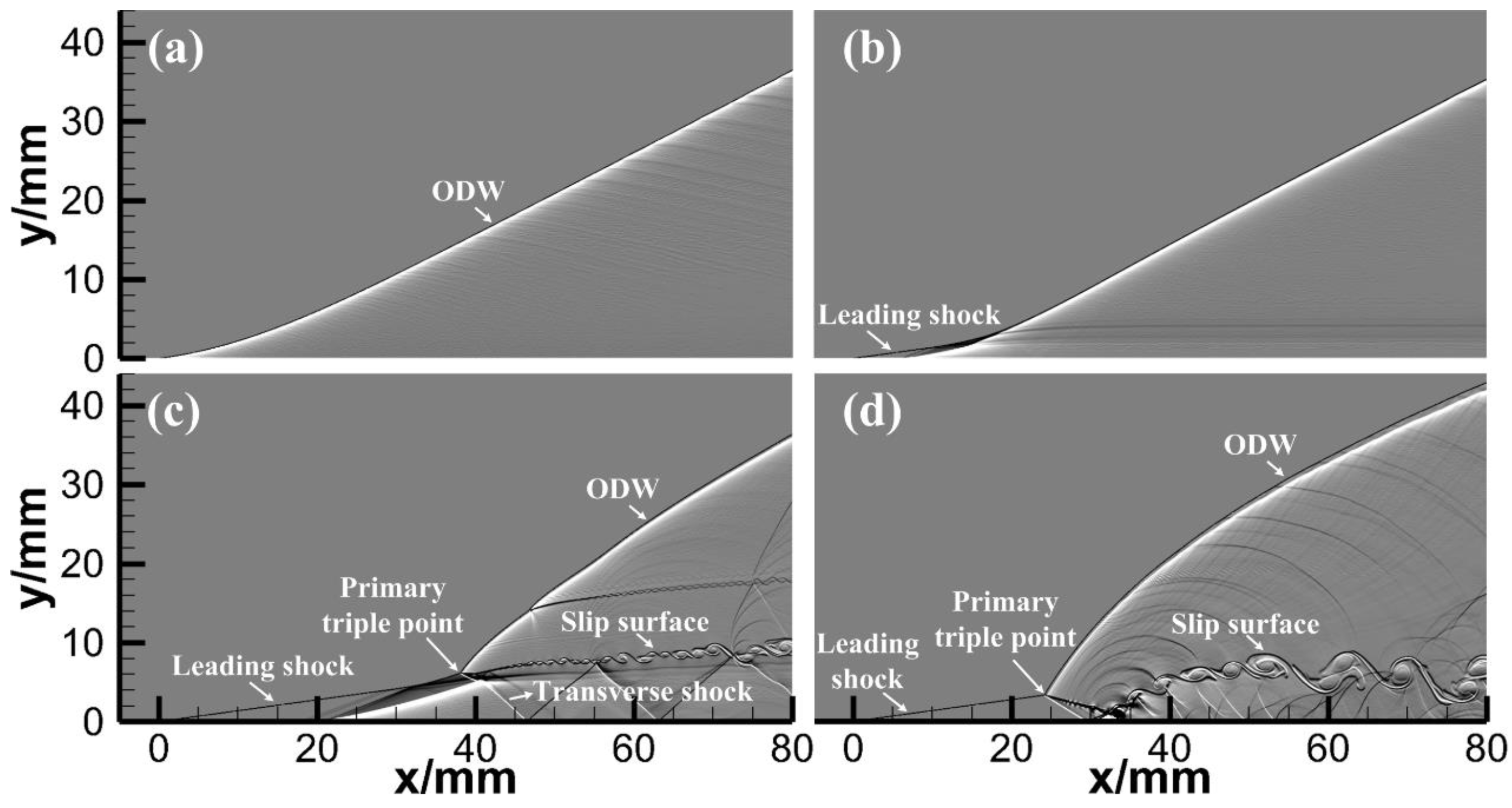
The typical structure of an oblique detonation wave (ODW) consists of a leading shock wave followed by a coupled shock-flame complex. The distance from the leading shock’s originating point to the ignition onset is referred to as the induction length. This work numerically studies the induction length effect using a two-step induction-reaction kinetic model. Results reveal that the induction length governs the transition pattern of ODWs. By testing four distinct induction lengths, four ODW regimes are identified, including a prompt ODW, a delayed smooth ODW, a delayed abrupt ODW, and a delayed abrupt ODW with an upstream triple point in oscillatory motion. The mechanisms behind these regimes are analyzed in detail. Additionally, hysteresis is observed when the induction length decreases from a larger value, demonstrating that this phenomenon can be influenced by the kinetic process.

1. Introduction

Oblique detonation waves (ODWs) have been proposed for hypervelocity propulsion for many years. Oblique detonation wave engines are representatives of such applications [1,2,3,4]. An ODW is a complex consisting of a coupled oblique shock wave and flame front. The fine structures of ODWs are of significant importance for fundamental investigation, for they are related to ODW stabilization and propulsive performance. For a typical ODW, a stable detonation usually cannot be established immediately behind the leading shock wave. Instead, an ignition delay distance exists between the originating point of the leading shock and the ignition onset. Silva and Deshaies [5], Wang et al. [6], and Teng and Jiang [7] numerically investigated the shift in the flow structure from the leading shock to the development of the ODW. They discovered that the transition pattern is either smooth or abrupt, depending on some criteria they proposed. As such, a criterion problem remains one of the most important concerns over ODW morphology; some new criteria have been proposed in recent years [8,9]. Through hypervelocity projectile experiments, more structures (or combustion regimes) of ODWs were discovered. Verreault and Higgins [10] found that ODWs can be prompt with no ignition delay if the leading shock wave is sufficiently strong. In their experiments, other combustion regimes, including combustion instabilities, decoupled shock-induced combustion, and inert shock waves, are also observed under different initial gas pressures or cone angles. Zhang et al. [11], Xiang et al. [12], and Han et al. [13] numerically or experimentally investigated the effects of a blunt bump on the wedge serving as an ODW initiator, demonstrating that a blunt bump can significantly shorten the ignition delay, alter the flow structure in the induction region, and accelerate the initiation process. Yang et al. [14] numerically studied the instability of oblique detonation waves with a two-step induction–reaction kinetic model, and found that instabilities tend to occur on the ODW surfaces as the reaction length is reduced at a fixed induction length. Zhang et al. [11,15], Wang et al. [16] numerically studied the control of the induction zone by hot jets and therefore the variation of the structures of ODWs. In our previous study [17], the hysteresis phenomenon was discovered as the wedge angle was dynamically varied, rendering different triple point structures. Based on this phenomenon, an instantaneous energy deposition is introduced into an inert shock wave flow field in combustible gases, thereby realizing ODW initiation [18]. All the studies on ODW structures mentioned above suggest that the ODW structures are closely associated with the kinetic process, especially the parameter of induction length. Therefore, the morphology, the transition pattern, the initiation, and the standing stability of ODWs are probably dominated by the induction length. However, the details regarding the effects of the induction length on ODWs remain unclear since previous studies involve different inflow conditions and the size parameters of ODW initiators (cones or wedges). Therefore, a specific study on the induction length effect is still needed based on the controlled variable method. In this study, we will use a two-step induction-reaction kinetic model to conduct numerical simulations to elucidate such an issue. By changing the induction length while keeping a fixed reaction length value and other boundary conditions, we will specifically reveal the induction length effect on ODW structures.

2. Numerical Treatment

The numerical treatment is consistent with our previous studies in terms of methodology [17,18,19]. The governing equations are two-dimensional unsteady reactive Euler equations given as:
Continuity equation
ρ / t + ( ρ u ) / x + ( ρ v ) / y = 0
where ρ is the density, u is the x-direction velocity, v is the y-direction velocity, and t is the time.
Conservation equation of x-direction momentum
( ρ u ) / t + ( ρ u 2 + p ) / x + ( ρ u v ) / y = 0
where p is the static pressure.
Conservation equation of y-direction momentum
( ρ v ) / t + ( ρ u v ) / x + ( ρ v 2 + p ) / y = 0
Conservation equation of energy
( ρ e ) / t + u ( ρ e + p ) / x + v ( ρ e + p ) / y = 0
where e is the specific total energy.
The equation of state for a perfect gas is:
p = ρ R T
where R is the gas constant and T is the static temperature. Therefore, the specific total energy can be expressed as:
e = p / ρ ( γ 1 ) + ( u 2 + v 2 ) / 2 R T 0 q ˜
where γ is the specific heat ratio, T 0 is the static temperature of the inflow, and q ˜ is the dimensionless local heat release using R T 0 for normalization, i.e., q ˜ = q / R T 0 , where q is the dimensional local heat release.
A two-step reduced reaction kinetic model developed by Ng et al. [20] is employed, which consists of a thermally-neutral induction step and a rapid heat-release step. The reaction rate equations for both steps are given as:
( ρ ξ ) / t + ( ρ u ξ ) / x + ( ρ v ξ ) / y = H ( 1 ξ ) ρ k I exp E I ( 1 / R T S 1 / R T )
( ρ λ ) / t + ( ρ u λ ) / x + ( ρ v λ ) / y = 1 H ( 1 ξ ) ρ k R ( 1 λ ) exp E R / R T
where ξ is the reaction progress variable of the induction step, k I is the reaction rate constant of the induction step, which controls the induction length, and E I is the activation energy of the induction step. λ is the reaction progress variable of the heat-release step, k R is the reaction rate constant of the heat-release step, which controls the reaction length, and E R is the activation energy of the heat-release step. T S is the temperature inside the induction region of a detonation wave. H ( 1 ξ ) is a step function defined as:
H ( 1 ξ ) = = 1     ,             i f         ξ < 1 = 0     ,             i f       ξ 1
Clearly, at any instant, the dimensional local heat release q satisfies q = λ Q , and the dimensionless local heat release q ˜ satisfies   q ˜   = λ   Q ˜ , where Q is the dimensional total heat release by the reactant, and Q ˜ is the dimensionless total heat release ( Q ˜   = Q / RT 0 ).
In this study, numerical simulations are conducted using an open-source computational fluid dynamics (CFD) code named AMROC [21]. AMROC uses the finite-volume method to solve the equations and incorporates a block-structured adaptive mesh refinement method to achieve high numerical resolution in regions of flow-field discontinuities. For discretization, we employ the MUSCL-Hancock scheme, which provides second-order accuracy, and pair it with the hybrid Roe method as the Riemann solver. To ensure numerical stability, the Van Albada limiter is applied to maintain total variation diminishing (TVD) properties. The source term is handled through the fractional step using the Godunov splitting method [22] to address the challenges of the stiff chemistry.
Figure 1 shows the computational domain of this study, which is a rectangular region. The left and top boundaries are the inflow boundary, and the bottom boundary in the range of 0   mm x 80   mm is a fixed wall which serves as a wedge to initiate the oblique detonation wave. The angle between the inflow direction and the horizontal direction is 30 , which represents the wedge angle. The right boundary and the part of the bottom boundary where 5   mm x < 0   mm are set as the outflow boundary.
The simulated incoming flow condition has a Mach number of 7.0, a static temperature of 300 K, and a static pressure of 20 kPa. The dimensionless heat release is set to be Q ˜ = 20 . The values for the gas constant and the specific heat ratio are set as R = 377.9   J / ( kg K ) and γ = 1.3 , respectively. The dimensionless activation energies for the induction step and the heat release step are given by E I / R T S = 4.8 and E R / R T S = 1.0 , respectively. The reaction rate constant of the heat release step k R is set to be a certain value such that the reaction length corresponding to a CJ detonation is L r = 0.66 mm . Keeping k R fixed, we can alter the reaction rate constant of the induction step k I to change the induction length L i (corresponding to a CJ detonation). Four different values of L i are tested, including 0.01 mm, 0.37 mm, 1.15 mm, and 2.3 mm.
The adaptively refined mesh can achieve a resolution of 0.025   mm × 0.025   mm in regions of flow-field discontinuities, which is sufficient for capturing fine structures of ODWs according to our previous study [17]. However, grid convergence is difficult to test because the minimum induction length in this study is as short as 0.01 mm. Since it has been demonstrated that a shorter induction length can suppress the instability of an ODW [20], it is believed that the grid resolution used is enough for the 0.01 mm case. It is also important to note that in this study, all flow fields will be presented using numerical schlieren in the form of the derivative ρ / y .

3. Results and Discussions

3.1. Effect of the Induction Length on the ODW Structure and Transition Pattern

Figure 2 shows four different final flow fields of ODWs corresponding to four different induction lengths mentioned in Section 2. Clearly, by adjusting the reaction rate constant of the induction step while keeping all other conditions unchanged, we can obtain noticeably different ODW structures and transition patterns. When L i = 0.01   mm (Figure 2a), the induction length is so short that there is almost no ignition delay behind the leading shock, and the ODW is the so-called prompt ODW according to Verreault and Higgins [10]. As the induction length is increased to L i = 0.37   mm (Figure 2b), a short ignition delay can be observed. However, the transition from the leading shock to the ODW is smooth, and no primary triple point exists. Therefore, the transition pattern is smooth under the condition of L i = 0.37   mm . When the induction length is increased to L i = 1.15   mm (Figure 2c), the induction step needs more time to finish, and therefore, the ignition delay and the primary triple point structure can be clearly observed. Obviously, the transition pattern now is abrupt, and the ODW is the so-called delayed ODW according to Verreault and Higgins [10]. It should be noted that the primary triple point L i = 1.15   mm is located near the end of the deflagration. In contrast, as the induction length is further increased to L i = 2.3   mm (Figure 2d), the primary triple point forms at a greater distance from the wedge tip during the initiation stage and moves upstream later on, swallowing the deflagration and approaching the wedge tip more closely than in the L i = 1.15   mm case. Therefore, in this condition, there is no deflagration anymore. Such an upstream-moving triple point structure was also discovered by Liu et al. [23]. They concluded that the triple point will move upstream when the inflow Mach number is relatively low. However, our current numerical results reveal that the upstream motion of the triple point seems to be controlled by the induction length. This means that once the induction length reaches some relatively larger value, destabilization of the primary triple point structure of an ODW tends to occur. In fact, for the case of L i = 2.3   mm , the primary triple point, not only moves upstream, but it also exhibits an oscillatory motion, which will be discussed in detail in the next section.

3.2. Oscillatory Motion of the Upstream Primary Triple Point

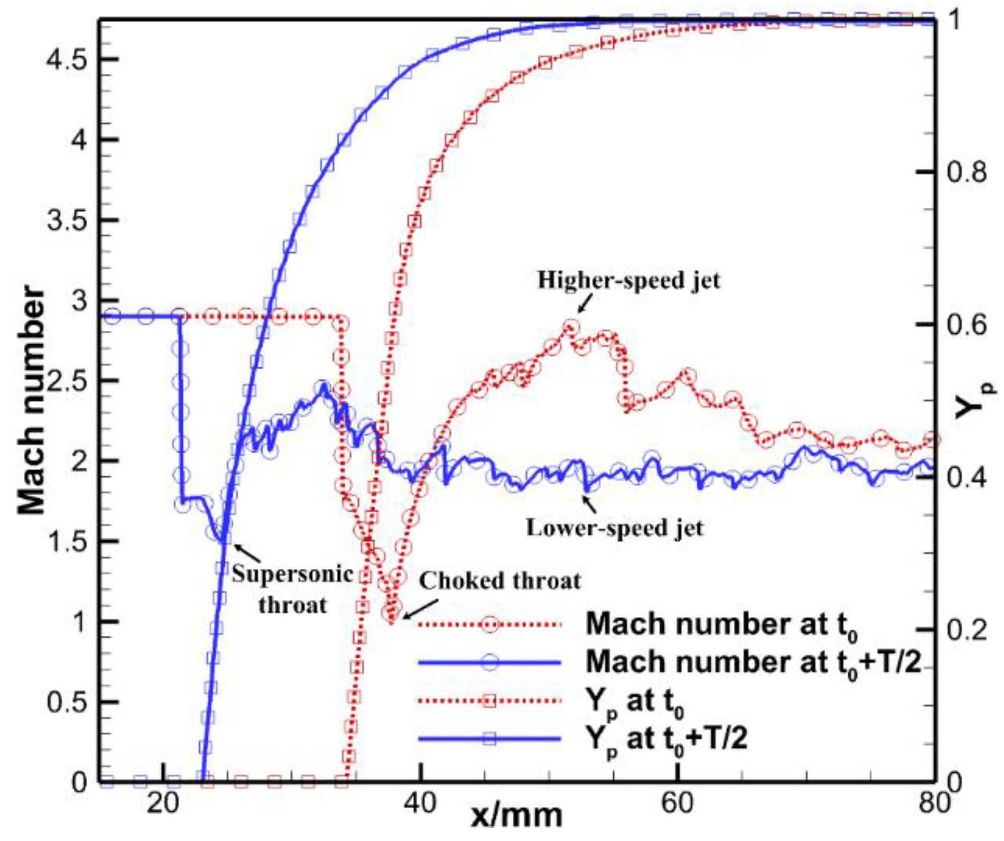
For the case of L i = 2.3   mm , the highly unstable, oscillatory motion of the primary triple point is shown in Figure 3. Figure 3a shows the flow field at time t 0 when the primary triple point is located at the farthest position away from the wedge tip. Figure 3b shows the flow field at time t 0 + T 1 / 2 when the triple point moves to the nearest position away from the wedge tip, where T 1 180   μ s is the period for the oscillatory motion. The reason for such an oscillatory motion is the scale effect and will be explained below. As shown in Figure 3, the slip line together with the wedge surface forms an aerodynamic Laval nozzle. The transverse shock impinges and reflects on the wedge surface ahead of the throat of the aerodynamic Laval nozzle. At time t 0 + T 1 / 2 (Figure 3b), the distance from the wedge tip to the throat of the aerodynamic Laval nozzle is relatively small, leaving insufficient ignition delay distance to trigger combustion and heat release upstream of the throat, even after the transverse shock reflection. In comparison, that distance at time t 0 (Figure 3a) is large enough to trigger combustion. Thus, at time t 0 + T 1 / 2 , the throat is not choked and remains supersonic with a lower local product mass fraction. Whereas at time t 0 , the throat is choked (i.e., a sonic throat) with a higher local product mass fraction, as shown in Figure 4. Consequently, a higher-speed jet is formed in the divergent section of the aerodynamic Laval nozzle at time t 0 (see Figure 3a and Figure 4), driving the whole nozzle structure together with the primary triple point to move upstream. However, the distance from the wedge tip to the throat becomes smaller and smaller during the upstream-moving process of the primary triple point, finally rendering combustion behind the reflected transverse shock quenched. At this moment, the jet with a lower speed (see Figure 3b and Figure 4) cannot drive the whole structure upstream any longer, and the primary triple point starts to move back. In this way, the periodic oscillatory motion of the triple point comes into being. In brief, the scale effect is the mechanism of the oscillatory motion of the primary triple point.

3.3. Effect of the Induction Length on ODW Hysteresis

As introduced above, the hysteresis phenomenon of ODWs was discovered by the authors in a previous study [17]. Thus, it is natural to study whether the induction length has any effect on ODW hysteresis. In the previous work, the hysteresis was confirmed by varying the wedge angle. In this study, we will use another method to check the hysteresis. That is, we first obtain an ODW with a certain induction length, and then directly change the induction length and continue the simulation, taking the previous result as the initial condition. If we define the change of the induction length from a smaller one to a larger one as the positive path, and from a larger one to a smaller one as the negative path, we will find that the hysteresis only occurs along the negative path in the L i = 1.15   mm case, namely, the hysteresis exists when the induction length is changed from L i = 2.3   mm to L i = 1.15   mm , as shown in Figure 5. Clearly, although they have the same induction length of L i = 1.15   mm , the final ODW structure in this situation is different from that in Figure 2c. In Figure 2c, the ignition delay distance for L i = 1.15   mm is about 22 mm. Thus, after the induction length is changed from L i = 2.3   mm to L i = 1.15   mm , the deflagration remains swallowed by the transverse shock, leading to an almost unchanged triple point structure. However, if we further change the induction length from L i = 1.15   mm to L i = 0.37   mm along the negative path, the situation will be different. In Figure 2b, the ignition delay distance for L i = 0.37   mm is only 7.1 mm. When decreasing the induction length from L i = 1.15   mm to L i = 0.37   mm along the negative path, the deflagration reemerges ahead of the transverse shock. In this situation, while the primary triple point still exists at an initial stage, it rapidly propagates downstream and eventually goes out of the computational domain, resulting in the restoration of the smooth transition pattern. This observation confirms that the hysteresis is absent for L i = 0.37   mm and even shorter induction lengths.

4. Conclusions

This work numerically studies the induction length effect using a two-step induction-reaction kinetic model. Results reveal that the induction length governs the transition pattern of ODWs. Several conclusions are obtained as below:
(1) When the induction length is increased with other conditions kept constant, four ODW regimes are identified, including a prompt ODW, a delayed smooth ODW, a delayed abrupt ODW, and a delayed abrupt ODW with an upstream triple point in oscillatory motion.
(2) The mechanism of the oscillatory motion of the primary triple point for a large induction length lies in the scale effect within the aerodynamic Laval nozzle flow behind the transverse shock. That is, the periodic scale variation triggers and quenches the combustion periodically in the aerodynamic Laval nozzle. This leads to a periodic variation of the nozzle exit speed between a higher value and a lower one. Accordingly, it makes the primary triple point, together with the aerodynamic Laval nozzle, be pushed upstream and blown downstream periodically.
(3) Hysteresis is observed when the induction length decreases from a larger value to a smaller one. This demonstrates that the hysteresis phenomenon can be influenced by the kinetic process and is more likely to occur with a longer induction length rather than a shorter one.

Author Contributions

Conceptualization, Y.L. and S.S.; methodology, Y.L. and S.S.; software, Y.L., G.X. and S.S.; validation, Y.L. and S.S.; formal analysis, Y.L. and S.S.; investigation, Y.L., G.X. and S.S.; resources, Y.L.; data curation, S.S.; writing—original draft preparation, S.S.; writing—review and editing, Y.L.; visualization, Y.L. and S.S.; supervision, Y.L. and G.X.; project administration, Y.L.; funding acquisition, Y.L. All authors have read and agreed to the published version of the manuscript.

Funding

This work is supported by the National Natural Science Foundation of China NSFC No. 11702316 and the Independent Research Project of the Aerospace Technology Institute, China Aerodynamics Research and Development Center No. 2022-374.

Data Availability Statement

The data that support the findings of this study are available from the corresponding author upon reasonable request.

Acknowledgments

The numerical simulation tool in this work is the open-source computational fluid dynamics program AMROC, originally developed by Ralf Deiterding, and the corresponding references have been given in the reference list.

Conflicts of Interest

The authors declare no conflicts of interest.

References

  1. Jiang, Z.L. Standing oblique detonation for hypersonic propulsion: A review. Prog. Aerosp. Sci 2023, 143, 100955. [Google Scholar] [CrossRef]
  2. Ostrander, M.; Hyde, M.; Young, M.; Kissinger, R.; Pratt, D. Standing oblique detonation wave engine performance. In Proceedings of the 23rd Joint Propulsion Conference, San Diego, CA, USA, 29 June–2 July 1987. [Google Scholar] [CrossRef]
  3. Adelman, H.G.; Cambier, J.L.; Menees, G.P.; Balboni, J.A. Analytical and experimental validation of the oblique detonation wave engine concept. In Proceedings of the 26th Aerospace Sciences Meeting, Reno, NV, USA, 11–14 January 1988. [Google Scholar] [CrossRef]
  4. Zhang, Z.J.; Wen, C.; Yuan, C.K.; Liu, Y.F.; Han, G.L.; Wang, C.; Jiang, Z.L. An experimental study of formation of stabilized oblique detonation waves in a combustor. Combust. Flame 2022, 237, 111868. [Google Scholar] [CrossRef]
  5. Silva, L.F.F.; Deshaies, B. Stabilization of an oblique detonation wave by a wedge: A parametric numerical study. Combust. Flame 2000, 121, 152–166. [Google Scholar] [CrossRef]
  6. Wang, A.F.; Zhao, W.; Jiang, Z.L. The criterion of the existence or inexistence of transverse shock wave at wedge supported oblique detonation wave. Acta Mech. Sin. 2011, 27, 611–619. [Google Scholar] [CrossRef]
  7. Teng, H.H.; Jiang, Z.L. On the transition pattern of the oblique detonation structure. J. Fluid Mech. 2012, 713, 659–669. [Google Scholar] [CrossRef]
  8. Teng, H.; Tian, C.; Zhang, Y.; Zhou, L.; Ng, H.D. Morphology of oblique detonation waves in a stoichiometric hydrogen-air mixture. J. Fluid Mech. 2021, 913, A1. [Google Scholar] [CrossRef]
  9. Shi, X.; Xie, H.; Zhou, L.; Zhang, Y. A theoretical criterion on the initiation type of oblique detonation waves. Acta Astronaut. 2022, 190, 342–348. [Google Scholar] [CrossRef]
  10. Verreault, J.; Higgins, A.J. Initiation of detonation by conical projectiles. Proc. Combust. Inst. 2011, 33, 2311–2318. [Google Scholar] [CrossRef]
  11. Zhang, Y.C.; Xiang, G.X.; Yu, J.; Jin, K.; Goh, K.B. Accelerated initiation of oblique detonation induced by disturbance in detonative zone. Chin. J. Aeronaut. 2023, 36, 153–164. [Google Scholar] [CrossRef]
  12. Xiang, G.X.; Zhang, Y.C.; Zhang, C.F.; Kou, Y. Study on initiation mechanism of oblique detonation induced by blunt bump on wedge surface. Fuel 2022, 323, 124314. [Google Scholar] [CrossRef]
  13. Han, X.; Liu, Y.F.; Zhang, Z.J.; Zhang, W.S.; Yuan, C.K.; Han, G.L.; Jiang, Z.L. Experimental demonstration of forced initiation of kerosene oblique detonation by an on-wedge trip in an ODE model. Combust. Flame 2023, 258, 113102. [Google Scholar] [CrossRef]
  14. Yang, P.F.; Teng, H.H.; Ng, H.D.; Jiang, Z.L. A numerical study on the instability of oblique detonation waves with a two-step induction–reaction kinetic model. Proc. Combust. Inst. 2019, 37, 3537–3544. [Google Scholar] [CrossRef]
  15. Zhang, Y.C.; Xiang, G.X.; Gao, X.; Yu, J.; Hu, X.Q.; Xin, Y.R.; Li, D.Y.; Wang, Q. Study on initiation characteristics of oblique detonation induced by hydrogen jets in acetylene-air mixtures. Fuel 2023, 350, 128787. [Google Scholar] [CrossRef]
  16. Wang, A.F.; Bian, J.; Teng, H.H. Numerical study on initiation of oblique detonation wave by hot jet. Appl. Therm. Eng. 2022, 213, 118679. [Google Scholar] [CrossRef]
  17. Liu, Y.; Wang, L.; Xiao, B.G.; Yan, Z.H.; Wang, C. Hysteresis phenomenon of the oblique detonation wave. Combust. Flame 2018, 192, 170–179. [Google Scholar] [CrossRef]
  18. Liu, Y.; Chen, W.Q.; Wang, L.; Xiao, B.G.; Cai, X.D. Oblique detonation initiation by an instantaneous energy source in high-speed wedge flows. AIAA J. 2021, 59, 4794–4799. [Google Scholar] [CrossRef]
  19. Liu, Y.; Xiao, B.G.; Wang, L.; Wang, C. Numerical study of disturbance resistance of oblique detonation waves. Int. J. Aerosp. Eng. 2020, 2020, 8876637. [Google Scholar] [CrossRef]
  20. Ng, H.D.; Radulescu, M.I.; Higgins, A.J.; Nikiforakis, N.; Lee, J.H.S. Numerical investigation of the instability for one dimensional Chapman-Jouguet detonations with chain-branching kinetics. Combust. Theory Model. 2005, 9, 385–401. [Google Scholar] [CrossRef]
  21. Deiterding, R. Parallel Adaptive Simulation of Multi-Dimensional Detonation Structures. Ph.D. Dissertation, Brandenburgischen Technischen Universität Cottbus, Cottbus, Germany, 2003. [Google Scholar]
  22. Toro, E.F. Riemann Solvers and Numerical Methods for Fluid Dynamics, 3rd ed.; Springer: Berlin/Heidelberg, Germany, 2009. [Google Scholar]
  23. Liu, Y.; Wu, D.; Yao, S.B.; Wang, J.P. Analytical and numerical investigations of wedge-induced oblique detonation waves at low inflow mach number. Combust. Sci. Technol. 2015, 187, 843–856. [Google Scholar] [CrossRef]
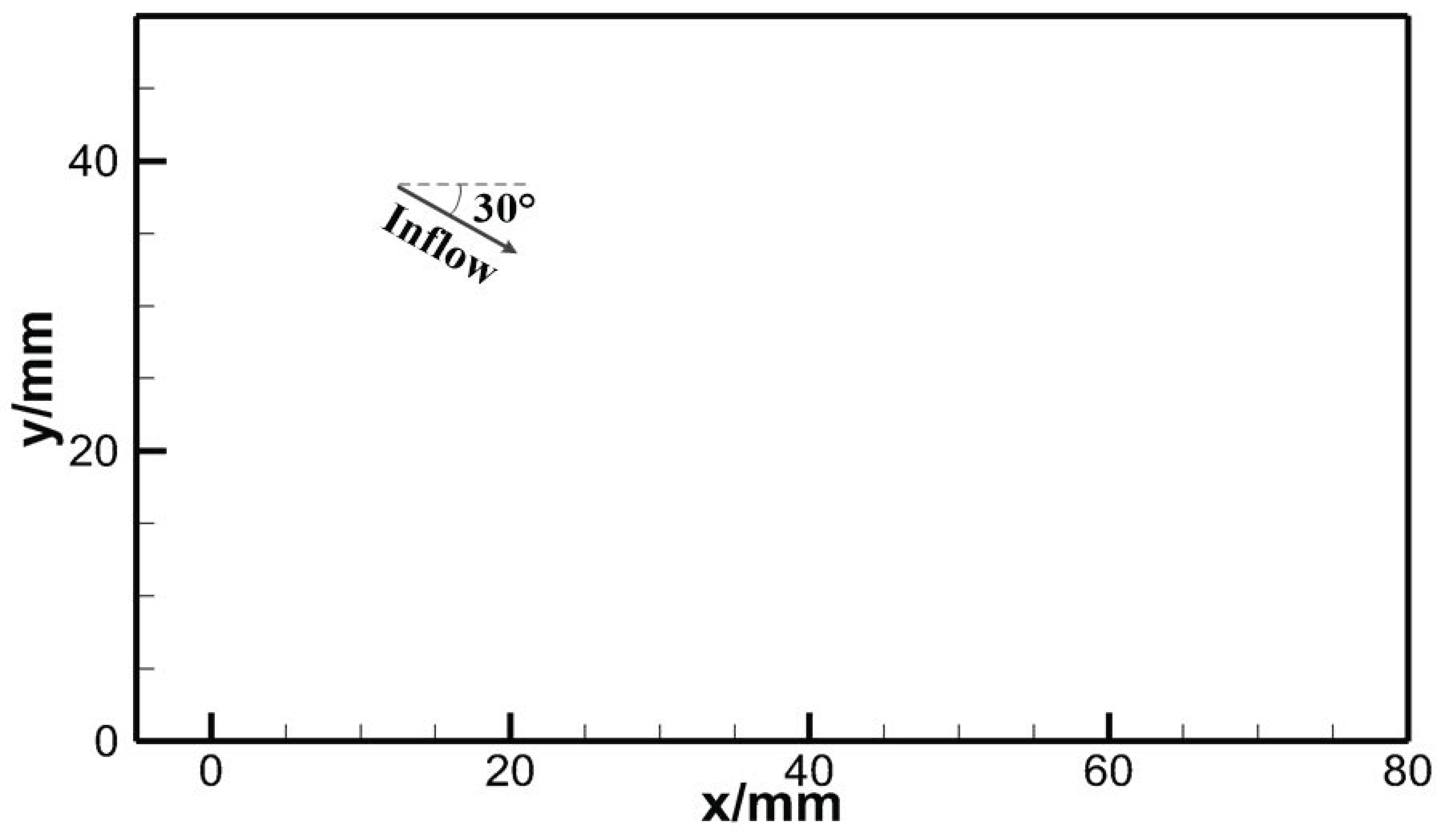
Figure 1. Schematic of the computational domain.
Aerospace 12 00792 g001
Figure 2. ODW structures for different induction lengths: (a) prompt ODW for L i = 0.01   mm ; (b) delayed smooth ODW for L i = 0.37   mm ; (c) delayed abrupt ODW for L i = 1.15   mm ; (d) delayed abrupt ODW with an upstream primary triple point in oscillatory motion for L i = 2.3   mm .
Aerospace 12 00792 g002
Figure 3. Oscillatory motion of the primary triple point at times: (a) t 0 ; (b) t 0 + T / 2 .
Aerospace 12 00792 g003
Figure 4. Mach number and product mass fraction distributions ( Y p ) on the wedge surface at different times.
Aerospace 12 00792 g004
Figure 5. The hysteresis loop of ODWs of different induction lengths.
Aerospace 12 00792 g005
Disclaimer/Publisher’s Note: The statements, opinions and data contained in all publications are solely those of the individual author(s) and contributor(s) and not of MDPI and/or the editor(s). MDPI and/or the editor(s) disclaim responsibility for any injury to people or property resulting from any ideas, methods, instructions or products referred to in the content.