Article

Design and Analysis of a Cushioning Airbag System for Heavy Airdropped Equipment in High-Altitude Environments

1
College of Astronautics, Nanjing University of Aeronautics and Astronautics, Nanjing 210016, China
2
National Key Laboratory of Aerospace Mechanism, Nanjing University of Aeronautics and Astronautics, Nanjing 210016, China
3
Key Laboratory of Exploration Mechanism of the Deep Space Planet Surface, Ministry of Industry and Information Technology, Nanjing University of Aeronautics and Astronautics, Nanjing 210016, China
*
Author to whom correspondence should be addressed.
These authors contributed equally to this work.
Aerospace 2025, 12(9), 768; https://doi.org/10.3390/aerospace12090768
Submission received: 8 July 2025 / Revised: 24 August 2025 / Accepted: 25 August 2025 / Published: 27 August 2025
(This article belongs to the Section Aeronautics)

Abstract

Airdropped equipment is important for cargo delivery and battlefield support. However, its development is constrained by the harsh conditions of high-altitude environments. To address the issues of low cushioning efficiency and instability of airdropped equipment in high-altitude environments, this study proposes a combined airbag system designed for the landing cushioning of heavy airdropped equipment under high-altitude and low-pressure conditions. A cylindrical side airbag and its folding–deployment scheme were developed. The cushioning performance of the proposed combined airbag was compared with that of a conventional airbag under two typical conditions. The effects of vent orifice opening pressure, vent orifice area, and main airbag height on cushioning performance were analyzed, along with their influence on the peak deceleration of the equipment. The airdrop environmental adaptability under complex interactive environments was evaluated through the Monte Carlo surrogate model method. The results indicate that the proposed combined airbag exhibits superior cushioning performance in high-altitude, low-pressure environments, reducing the peak deceleration by 44.9% and 50% under the two conditions. As the height of the main airbag increases, the peak overload of the equipment progressively decreases. In contrast, as the vent orifice area increases, the peak overload initially decreases and then increases. When the main airbag height is 1.35 m and the vent orifice area is 0.4 m2, the system achieves the best damping performance and landing stability at a 4500 m altitude environment. The overall airdrop success rate reaches 93.33% across various complex environments. This study provides a viable solution to meet the airdrop requirements of heavy equipment in high-altitude environments.

1. Introduction

With the increasing demand for cargo delivery and equipment transportation, the landing cushioning of heavy airdropped equipment has become a critical component. In China, plateau regions have an average altitude exceeding 4000 m, making the deployment of airdropped equipment in high-altitude, low-pressure environments a formidable challenge. Currently, airbag cushioning systems are widely utilized for heavy equipment airdrops [1]. Based on the cushioning principles, airbags are primarily classified into sealed airbags, vented airbags, and combined airbags. Due to the high cost and low repeatability of airdrop tests, research on cushioning airbags has predominantly relied on numerical simulations and analytical methods. Extensive research has been conducted by scholars in this field [2,3,4,5].
J. Kenneth Cole and Donald E. Waye developed an analytical mathematical model for the Mars Pathfinder’s airbag cushioning system to calculate the dynamic characteristics of both the airbag and the payload during the impact and rebound processes [6]. Jack B. Esgar and William C. Morgan developed an analytical model for cushioning airbags by treating the airbag interior as a container that conforms to the ideal gas law, neglecting the elasticity of the fabric and the mass of the internal gas. Their model was derived from thermodynamic equations combined with mechanical equilibrium equations [7]. Zhou X et al. addressed the dust issue caused by airbag venting during lunar landing and designed a novel combined cushioning airbag. They conducted analytical studies and experimental evaluations to assess its cushioning performance and parameter response [8]. Cao Pan et al. established an equivalent spherical airbag model using the discrete element method (DEM) and validated its applicability to airbag simulations through numerical experiments [9]. The most commonly used airbag modeling method is the control volume method (CV) [10], which offers faster computation than the Arbitrary Lagrangian–Eulerian (ALE) method and the discrete element method (DEM) while maintaining sufficient simulation accuracy.
The existing airbag cushioning systems can ensure the safe airdrop of equipment under standard operating conditions [11]. However, in high-altitude, low-pressure environments, insufficient airbag inflation significantly reduces cushioning performance and may even result in the overturning of airdropped equipment [12]. As future equipment becomes increasingly intelligent and precise, its mass is expected to increase while the allowable overload threshold decreases [13]. Additionally, after venting is completed, residual velocity may cause the equipment to undergo hard impacts with the ground [14]. To avoid the risk of hard landings in high-altitude airdrop environments, Li [15] proposed a study on exhaust port area matching technology. However, this method requires selecting different vent orifice areas based on varying airdrop altitudes, making it difficult to ensure the general applicability of the airbag cushioning system. Therefore, further investigation into methods for reducing the overload levels of airdropped equipment and enhancing the reliability of airbag cushioning systems in high-altitude, low-pressure environments is of significant practical importance. Although combined airbags have a complex structure, they provide the most effective solution for meeting these requirements.
Combined airbag systems have already been applied in Mars landing and lunar exploration missions [16,17]. The existing combined airbag systems are primarily divided into landing airbags for space probes and combined airbags for airdropped equipment. The American companies ILC Dover and Airborne Systems North America (ASNS) have designed airbag landing cushioning systems for the Orion Crew Exploration Vehicle (CEV) [18]. Both of them are combined airbags; however, their structures and the configurations of their outer airbags are different. These combined airbag systems have the same cushioning theory. Their outer airbag releases the absorbed energy through venting during the cushioning process, while the inner airbag provides secondary support to the sealed airbag. The combined airbag system for airdropped equipment has two airbags on the side, with exhaust ports between them [19]. However, most research focuses on sealed airbags and externally vented airbags [20,21,22]. There is limited research on combined airbag systems. While traditional airbags can meet most airdropping requirements under ordinary conditions, the continuous upgrading of airdropped equipment and the supply needs in plateau border areas have made it difficult to adapt to the cushioning demands of airdropped equipment in plateau environments. Under extreme conditions, risks such as rollover may even occur.
To address the aforementioned issues, this study designs a new combined airbag system suitable for high-altitude, low-pressure environments. The side airbags are sealed and receive the air vented from the main airbag. Once inflated, they provide lateral support for the airdropped equipment. The main airbag still retains a part of the gas to avoid insufficient inflation under low-pressure conditions.
Comparing with the traditional airbag system under high-altitude conditions, the results indicate that the new combined airbag provides excellent protection for the airdropped equipment in high-altitude environments. The new combined airbag also reduces landing overload and improves landing stability. Through an environmental adaptability assessment, the novel airbag is verified to maintain excellent cushioning performance across diverse environments, with its airdropping success rate reaching 93.33%.

2. Airbag Cushioning System Configuration Design

2.1. Airbag Cushioning System Configuration

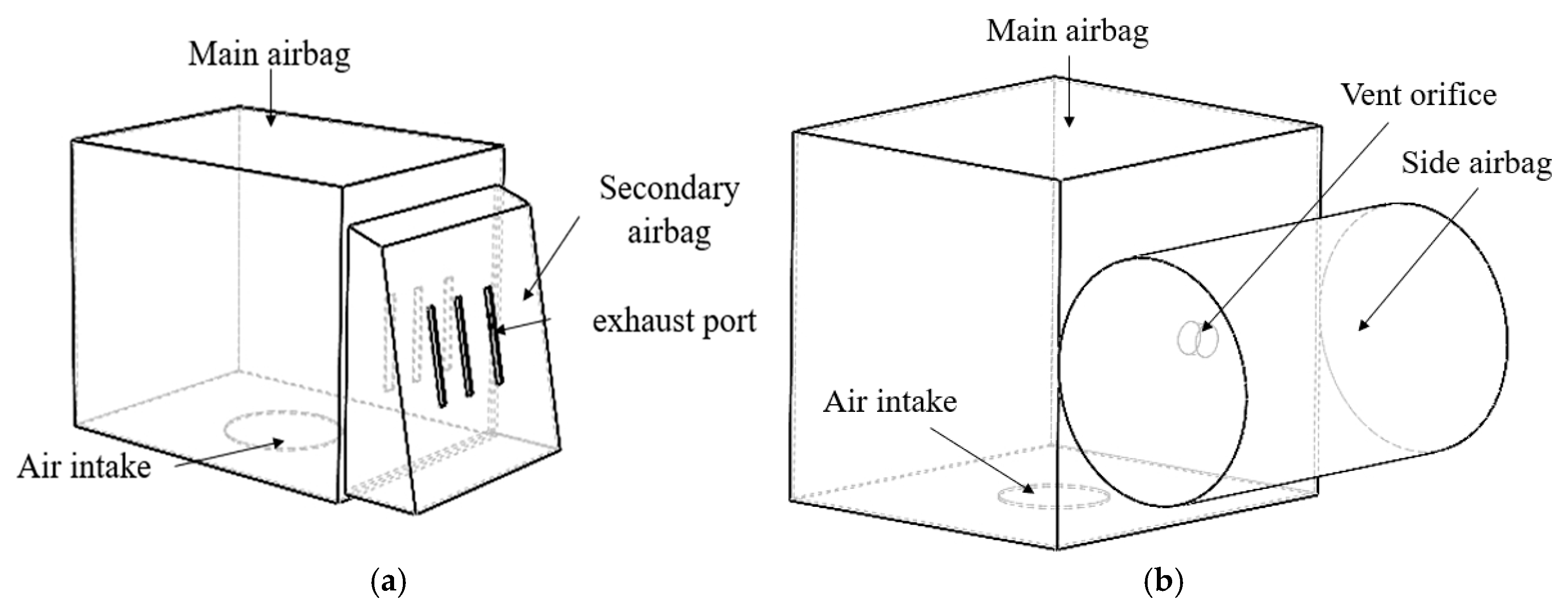
The heavy airdropped equipment weighs approximately 15 tons. The traditional airbag system and proposed combined airbag system are shown in Figure 1.
As shown in Figure 1, a structural comparison between the two airbags is presented. The traditional airbag features vent holes between the main and secondary airbags and exhaust holes on the secondary airbag. During the cushioning process, the energy of the airdropped equipment is dissipated through gas emission. The traditional airbag system was designed and utilized based on China’s previous-generation airdrop equipment, which had a mass of 8 t. While it could meet the overload requirements under ordinary working conditions for the older-generation equipment [11], it is inadequate for the new-generation airdrop equipment weighing 15 t. In this study, we scale the airbag dimensions based on the volume ratio between the traditional airbag and the legacy equipment while maintaining identical material parameters. This approach enables a rigorous performance comparison between traditional and new combined airbag systems under equivalent material conditions. In plateau environments, the traditional airbag configuration fails to provide optimal cushioning capability due to insufficient atmospheric pressure and an increased risk of lateral tilting under crosswind effects, which may cause the impact acceleration at touchdown to exceed the safety threshold, potentially damaging the equipment structure.
This study proposes a new dual-chamber sealed combined airbag system, as illustrated in Figure 1b. The system is a parallel configuration, which consists of a main airbag and a side airbag. The main airbag is designed with a standard cubic structure to provide vertical cushioning. The side airbag, initially folded and positioned adjacent to the main airbag, expands into a cylindrical shape upon inflation. The two chambers are interconnected, enabling gas transfer from the main airbag to the side airbag during compression, thereby facilitating lateral expansion.
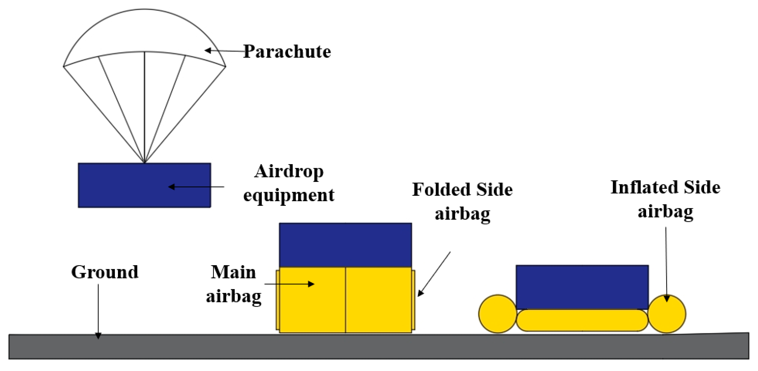
The vent orifice between the two chambers is equipped with exhaust valves to regulate the critical exhaust pressure. Compared with the passive exhaust mechanism of conventional designs, the proposed system transforms the main airbag’s exhaust process into an active inflation process for the side airbag. Under high-altitude and low-pressure conditions, this design helps maintain stable internal pressure within the system. Furthermore, the cylindrical support structure formed by the inflated side airbag significantly enhances the system’s lateral anti-tilt capability. While mitigating the risk of hard impacts, this design also enhances the wind resistance stability of the airdropped equipment. The cushioning and landing process of the airdropped equipment equipped with the new combined airbag system can be divided into three stages, as illustrated in Figure 2.
The cushioning and landing process consists of three distinct phases. (1) Parachute deceleration phase: The airdropped equipment is released from the transport aircraft, and both the parachute and airbag system deploy. (2) Stable descent phase: Under the influence of the parachute, the equipment descends steadily, and the main airbag is inflated by air. (3) Ground impact cushioning phase: After touchdown, the main airbag compresses and pushes the gas of main airbag into the side airbag. This process dissipates kinetic energy while simultaneously inflating the side airbag, which enhances lateral support for the airdropped equipment.

2.2. Airbag Design

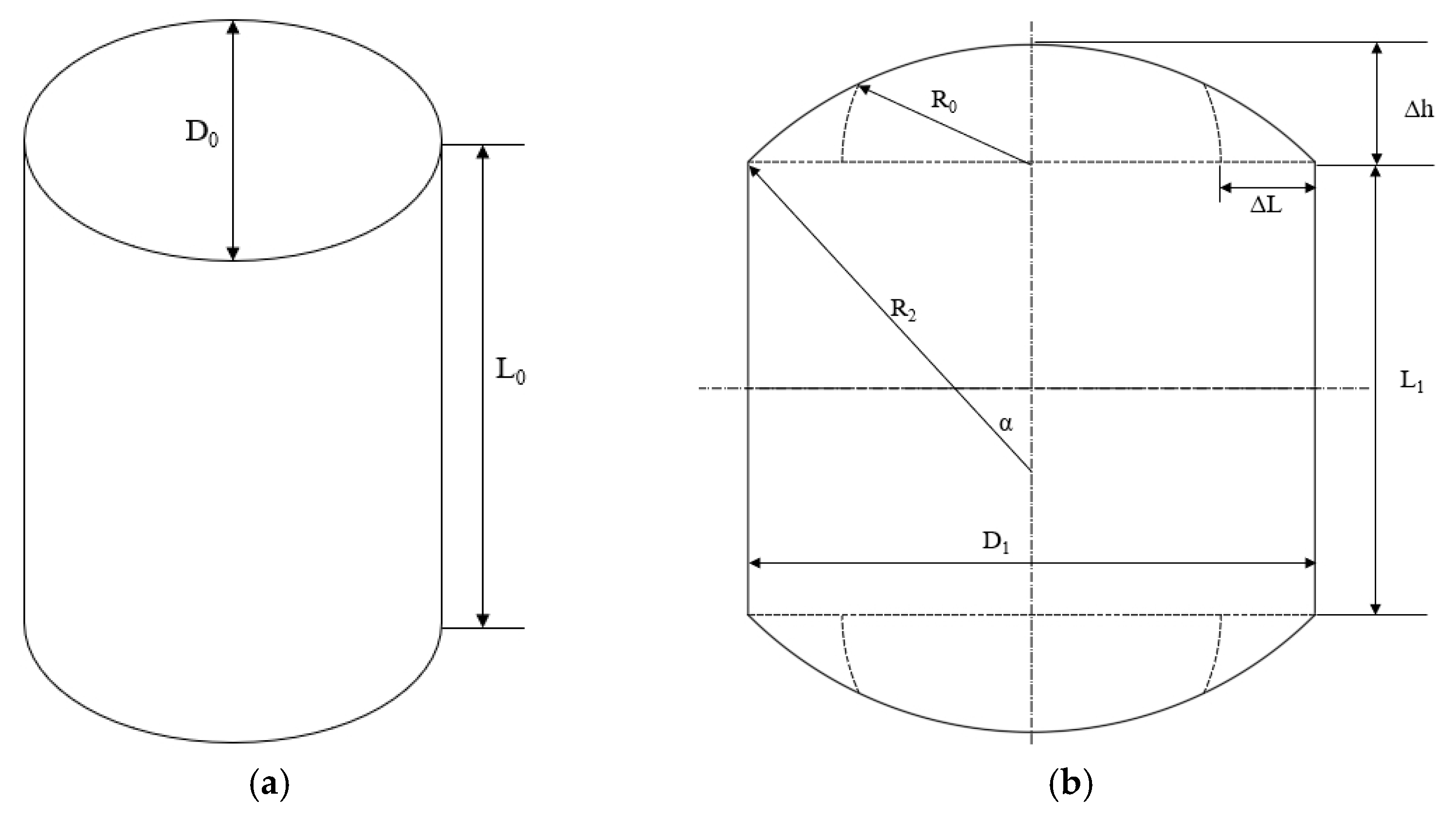
The side airbag is folded, as shown in Figure 3. Assuming the folded airbag is a regular cylinder. The airbag folding geometry in this study was constructed employing a direct folding methodology; the diameters of the upper and lower circular surfaces are the folded edges. As shown in Figure 3, before folding, the diameter of the airbag is D 0 . The height of the airbag is L 0 . The folded height L 1 can be expressed as
L 1 = L 0 2 Δ L = L 0 ( D 1 D 0 )
The width of the folded rectangle corresponds to the circumference of the base of the original cylindrical airbag, denoted as 1 2 π D 0 . The central angle of the sector region is 2 α . The relationship between the central angle and the radius of the sector plane can be expressed as
sin α = D 1 2 R 2 = π D 0 4 R 2
The area of the sector plane is given by
S 2 = 2 α 2 π π R 2     2 1 2 D 1 R 2 cos α = α R 2     2 1 2 D 1 R 2 cos α
When folded into eight sector-shaped planar sections, the resulting cylindrical airbag exhibits a total surface area S 1 expressed as
S 1 = 2 D 1 L 1 + 8 S 2
The surface area remains invariant before and after folding,
S 0 = S 1
Combining the above formulations yields
π D 0     2 2 + π D 0 L 0 = 2 D 1 L 1 + 8 α R 2 4 D 1 R 2 cos α
Since the surface area remains unchanged after folding, the relationship between the initial diameter and the sector radius can be expressed as
D 0     2 = 16 R 2     2 arcsin ( π D 0 4 R 2 ) π D 0 16 R 2     2 π 2 D 0     2 ( π 2 π )
The finite element model of the side airbag inflation process is shown in Figure 4. The side airbag is initially in a folded state, composed of a rectangle and a semi-ellipse. When the main airbag starts exhausting gas into it, the side airbag begins to deploy and eventually inflates into the rightmost configuration shown in the figure below.
During the actual inflation process, the elasticity of the fabric causes the elastic deformation of airbag surface. It also causes bulging at both ends. Assuming that the in-plane shear stress of the airbag fabric remains zero during inflation, the stress–strain relationship of the linearly elastic fabric material in the circumferential and axial directions can be expressed as
ε h = 1 E ( σ h v σ t )
ε t = 1 E ( σ t v σ h )
where ε h is the circumferential strain; ε t is the axial strain; σ h is the circumferential stress; σ t is the axial stress; E is the fabric’s elastic modulus; and v is the fabric’s Poisson’s ratio. The circumferential stress and axial stress can be expressed as
σ h = D 0 ( P 0 P a ) 2 d
σ t = D 0 ( P 0 P a ) 4 d
where P 0 is the air pressure in the inflated side airbag; P a is the ambient pressure; d is the fabric thickness of the side airbag. The diameter of the cross-section and the increased axial length of the deformed main airbag are given by
D s = D 0 ( 1 + ε h )
L s = L 0 ( 1 + ε t )
where D s is the cross-sectional diameter of the side airbag, and L s is the axial length of the side airbag.
The cylindrical airbag undergoes significant deformation at its end surfaces, with the post-deformation profile capable of being approximated as [23]
ω = R s 1.45 ( P 0 P a ) R s E d 1 v 2 2.08 + 4 v 1.2 v 2 3 cos ( π r D s )
where R s is the cross-sectional radius of the side airbag.
The maximum displacement of the end face profile is
ω max = R s 1.45 ( P 0 P a ) R s E d 1 v 2 2.08 + 4 v 1.2 v 2 3
The total length of the inflated airbag is
L t = L S + 2 ω max
The total volume of the airbag is
V t = π R s     2 L s + 2 ( 1 2 π ) ω max D S
The new combined airbag system provides comprehensive protection for the airdropped equipment. In addition to reducing cushioning overload, it effectively mitigates the risk of hard impacts upon ground contact. The lateral support formed by the side airbag actively prevents lateral overturning and collisions caused by crosswind disturbances.

3. Analysis of the Cushioning Performance of the Airdrop System in High-Altitude Environments

3.1. Finite Element Modeling and Mesh Independence Verification

Compared with airdrops in low-altitude regions, airdrops at high altitude have unique characteristics. Taking a high-altitude region at 4500 m above sea level as an example, the average atmospheric pressure is 57,715 Pa, which is approximately 0.57 times the standard atmospheric pressure. The average air density is 0.77695 kg/m3, about 0.63 times that of standard atmospheric conditions [20]. As parachutes and self-inflating airbags use air as the working medium, their performance deteriorates significantly in high-altitude environments. This often leads to large impact overloads or even equipment overturning. This section analyzes the cushioning performance of two airbag systems in high-altitude environments and explores the advantages of the new combined airbag cushioning system.
The airdropped equipment cushioning system uses eight sets of airbags. Every set of airbags is independent of the others and evenly arranged at the bottom of the equipment with fixed connections. The airbags are modeled using shell elements [21]. In the initial state, the side airbags are in a folded configuration. In the LS-DYNA implementation, the airbag properties are defined using Material Type 34 (MAT_FABRIC). The modeling parameters are shown in Table 1.
During landing, the airbags undergo substantial deformation, leading to contact between adjacent airbags. The cushioning system is modeled with self-contact and solved using a penalty function approach. The airbags are fixedly connected to the airdropped equipment, while the ground is modeled as a rigid body. To prevent interpenetration, a minimum clearance is set between the airbags and the ground, along with an appropriate penalty stiffness scaling factor. Hourglass control is introduced in the computation to enhance the reliability of the simulation results. The Finite element model are shown in the Figure 5. Different colors represent different airbags.
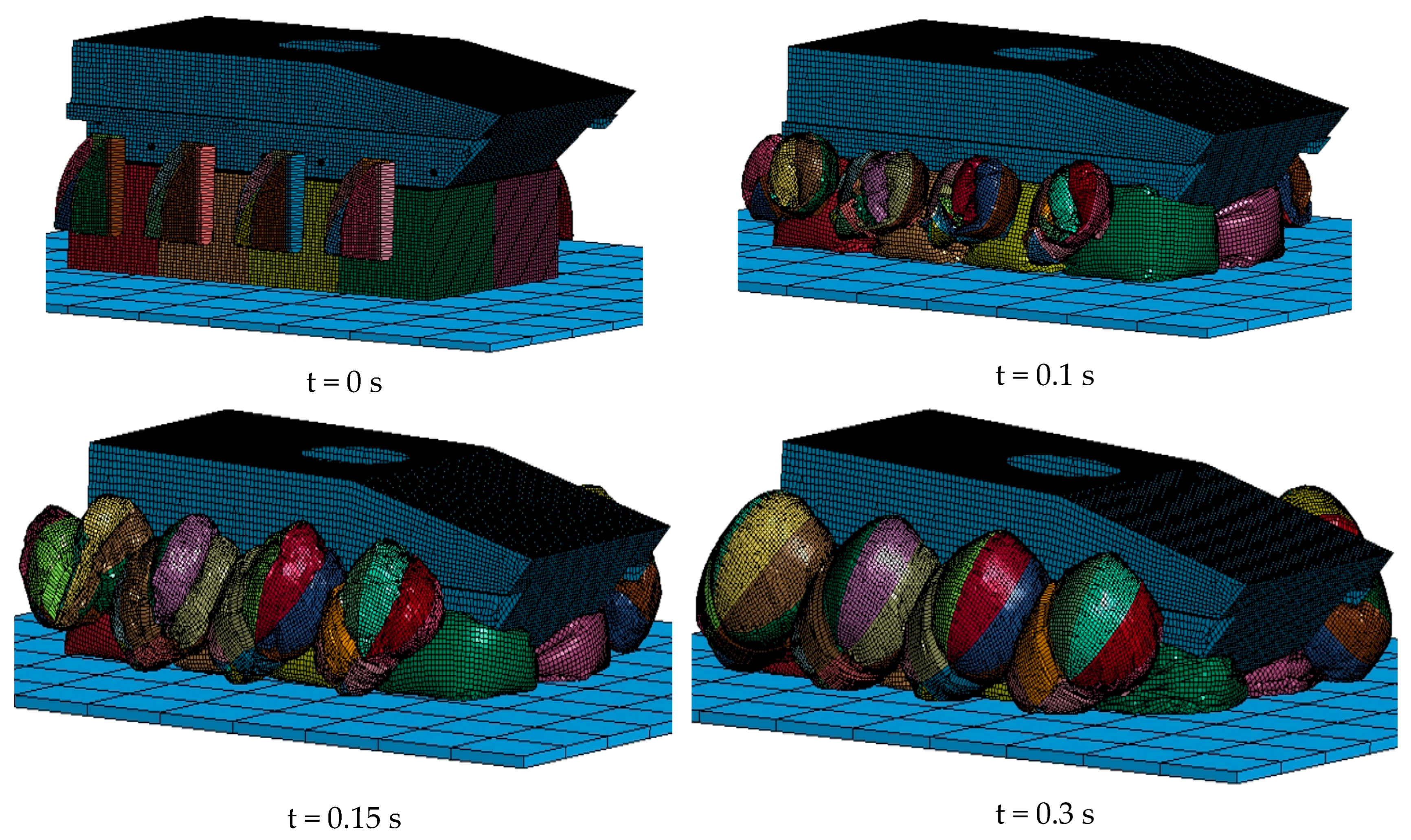
The simulation process diagram under normal operating conditions is shown in the Figure 6. Different colors represent different airbags.
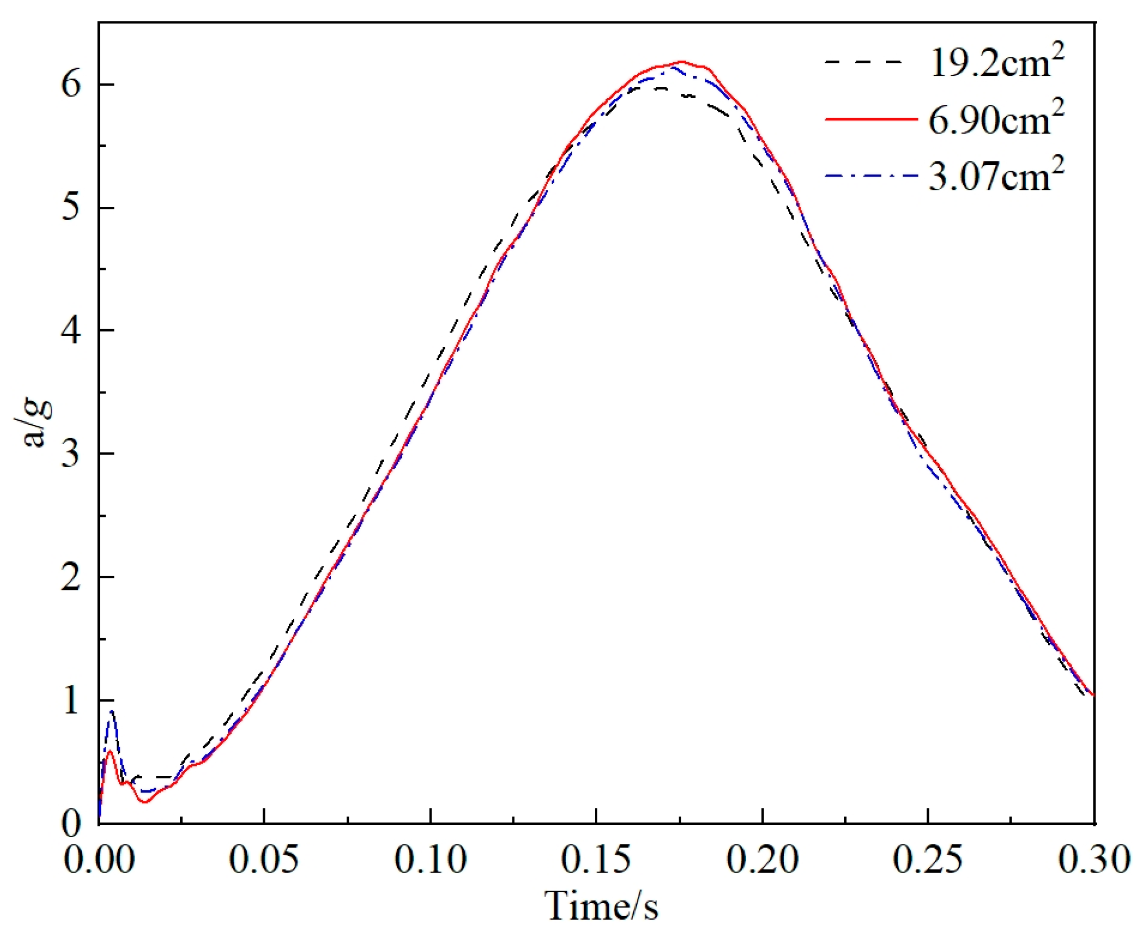
To ensure the reliability of finite element results and computational accuracy, mesh independence verification was conducted. A progressive mesh refinement strategy was adopted, using three mesh sizes with areas of 19.2 cm2, 6.9 cm2, and 3.07 cm2, respectively. The verification case was set under standard atmospheric pressure with a vertical velocity of 8 m/s, no crosswind, and zero ground slope. The acceleration responses of the equipment under the three meshes are shown in Figure 7.
As shown in the result comparison, the discrepancy between the mesh areas of 6.9 cm2 and 3.07 cm2 is negligible, while the cushioning performance differs significantly for the 19.2 cm2 mesh. It can be concluded that the simulation results are independent of mesh size when the mesh area is 6.9 cm2, and this size offers shorter computation time compared with that for 3.07 cm2. Thus, a mesh area of 6.9 cm2 is selected in this study.

3.2. Analysis of the Cushioning Performance of the New Combined Airbag

This study focuses on the cushioning process of airdropped equipment at the moment of landing, in which both the release and deceleration processes are reflected in its landing parameters.
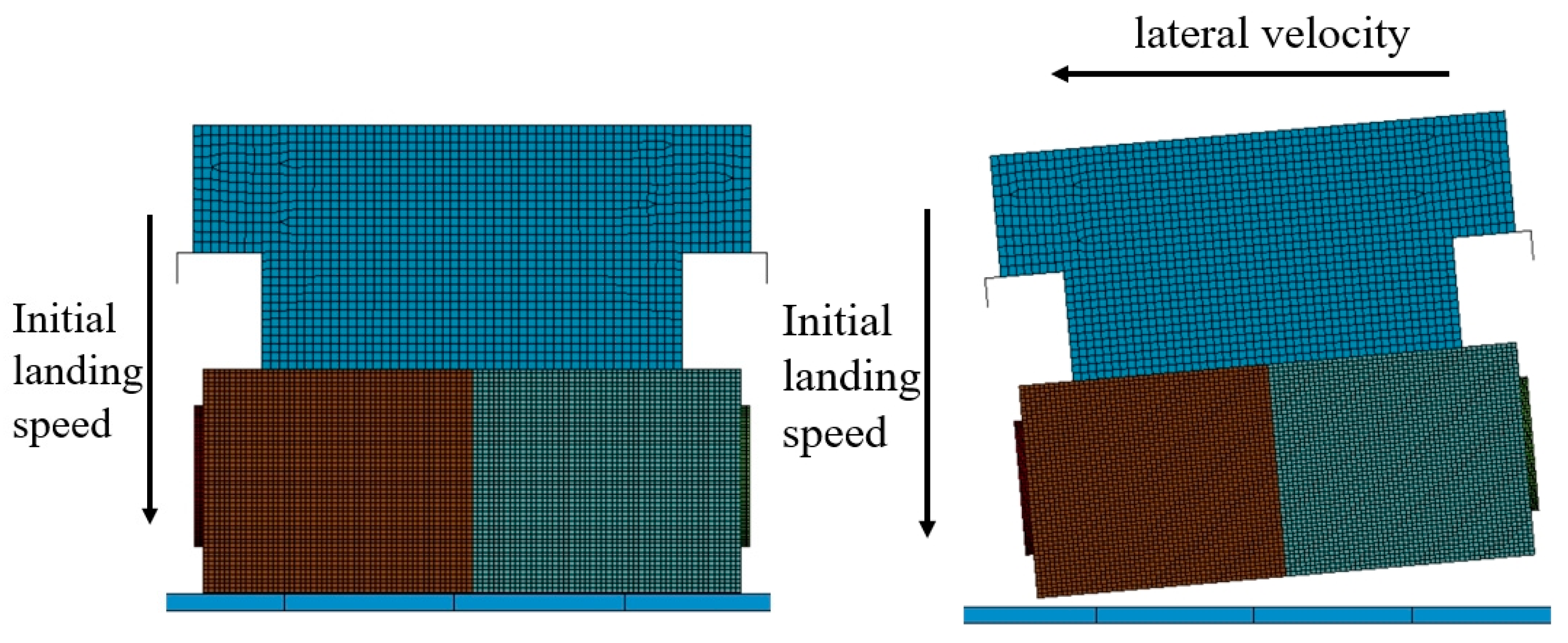
In high-altitude environments, the airdropped equipment is affected by environmental factors. This study conducts a comparative analysis based on two conditions: (1) The equipment descends vertically without lateral velocity or tilt. (2) The equipment possesses lateral velocity and an initial tilt angle. The specific parameters for these two conditions are shown in Table 2 and illustrated in Figure 8. Different colors represent different airbags.
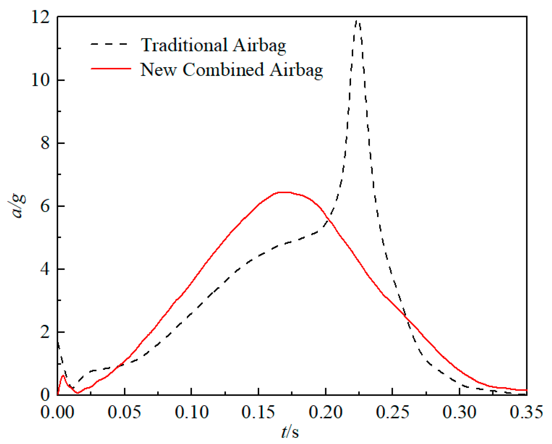
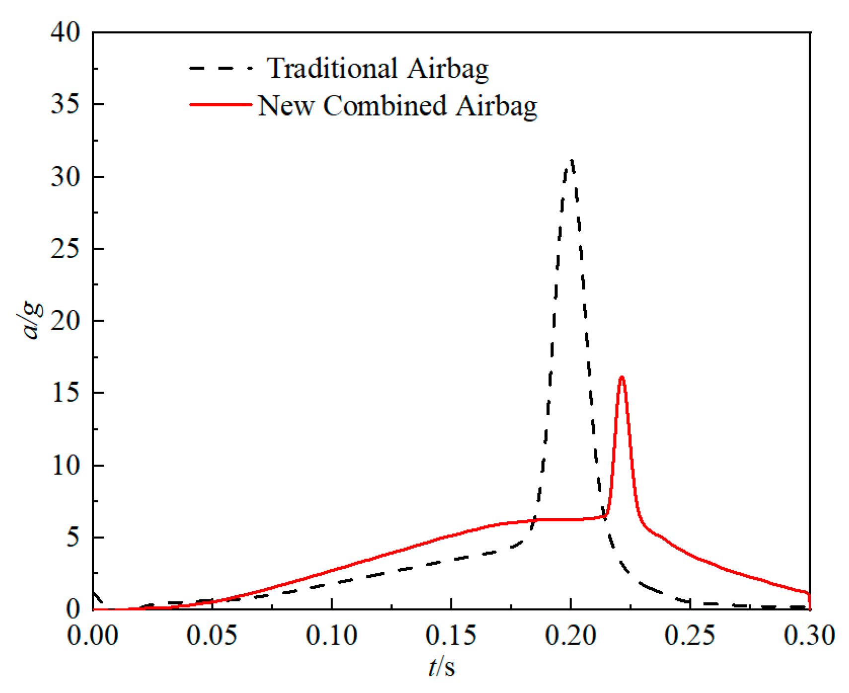
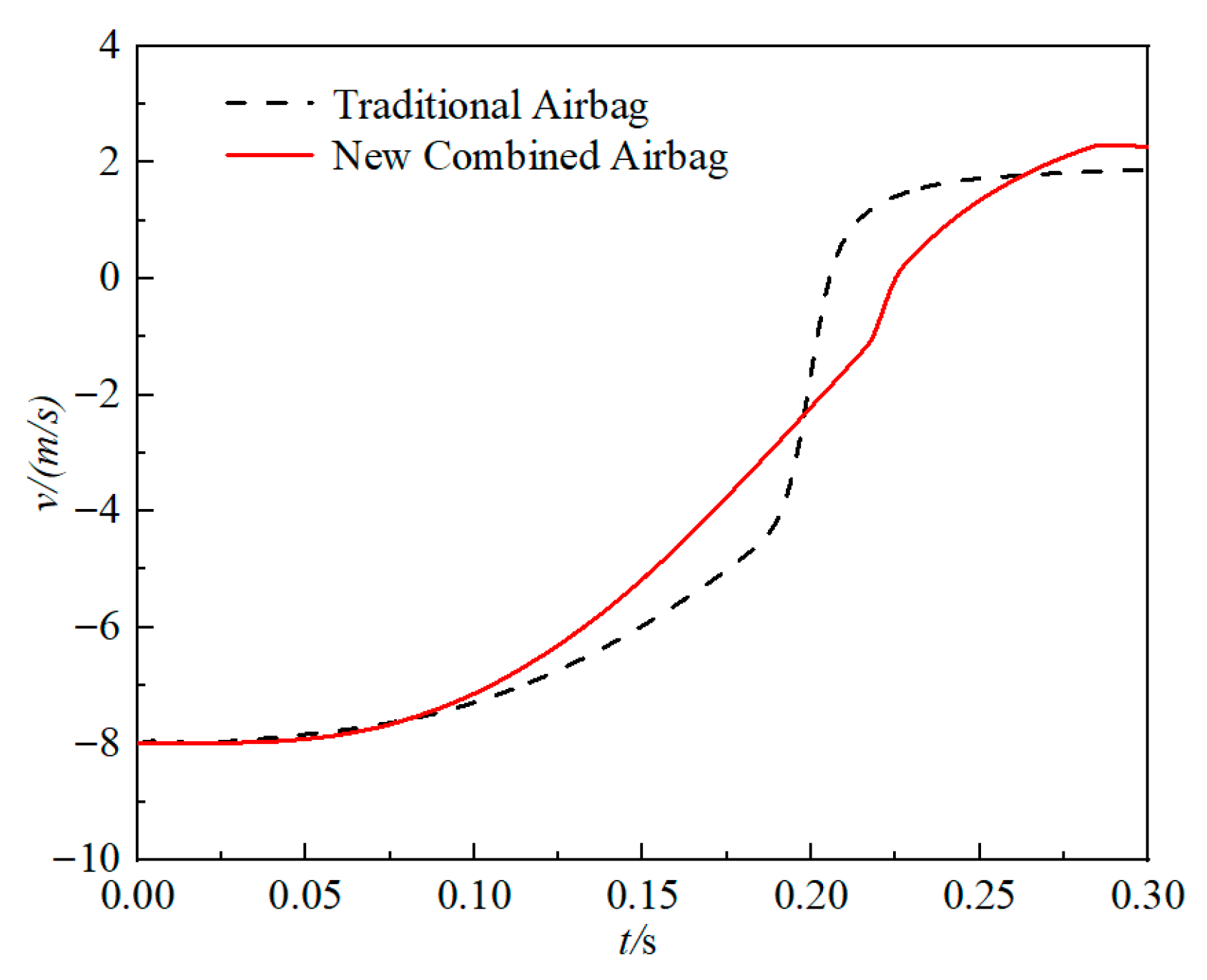
The overload acceleration and velocity for the airdropped equipment under the two conditions are shown in Figure 9, Figure 10, Figure 11 and Figure 12.
The new combined airbag cushioning system exhibits significant performance advantages, with the acceleration peak occurring at 0.18 s. The maximum acceleration is reduced from 11.8 g to 6.5 g, resulting in a 44.9% reduction in peak overload The rebound speed slightly increases. It proves that the new airbag system enhances the protection for airdropped equipment under low-pressure conditions and mitigates the risk of hard impacts.
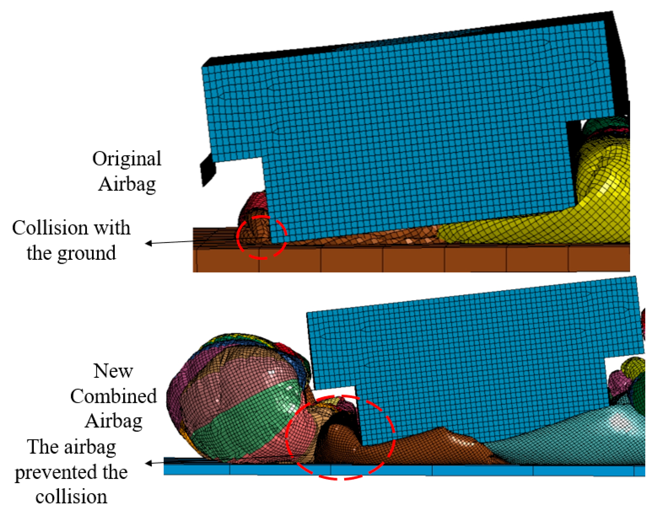
In high-altitude and low-pressure environments, with equipment tilting and lateral velocity increase, the performance of the airbag system significantly decreases. It makes the airdrop missions more dangerous. The equipment impacts the ground under both airbag configurations, which causes a sharp increase in acceleration at the moment of landing. The equipment equipped with the traditional airbag undergoes a severe impact at 0.2 s, with a maximum overload of 34.5 g. In contrast, the equipment using the new combined airbag collided with the ground at 0.23 s, with a significantly lower overload of 16.6 g. This reduction is attributed to the fact that the new combined airbag does not release gas outward, instead retaining a portion of the gas inside the main airbag. The side airbag provides flexible lateral support. As a result, the maximum overload is reduced by more than 50%, substantially mitigating the damage caused by hard impacts, as shown in Figure 13.

4. The Impact of New Combined Airbag Parameters on the Cushioning Effect

Although the new airbag system has a better cushioning performance in high-altitude environments, the equipment may still impact the ground. This study analyzes the parameters that influence airbag cushioning performance. First, the opening pressure of the vent orifice is analyzed. Based on the optimal opening pressure, the effect of additional airbag parameters on cushioning performance is examined to determine the optimal configuration for the new airbag system.

4.1. Effect of Vent Orifice Exhaust Pressure on Airbag Cushioning Performance

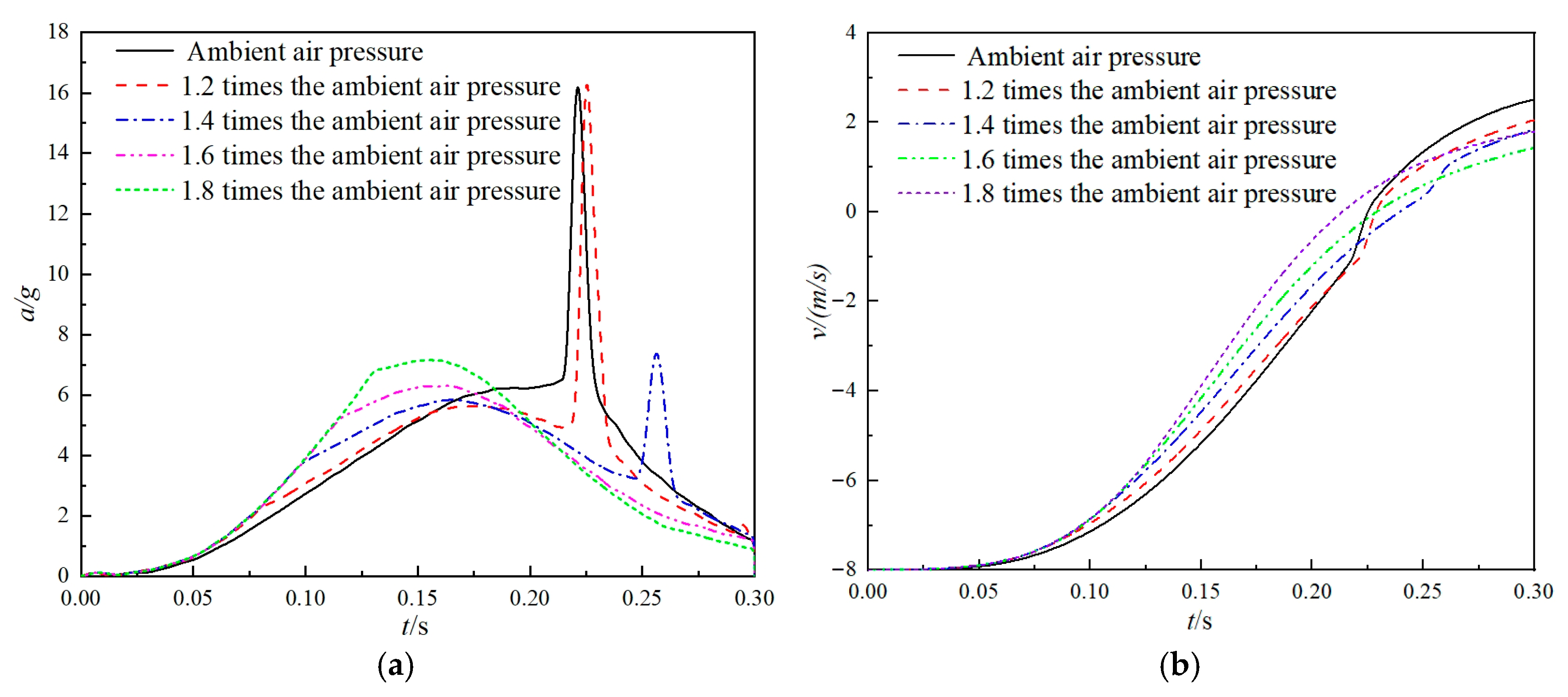
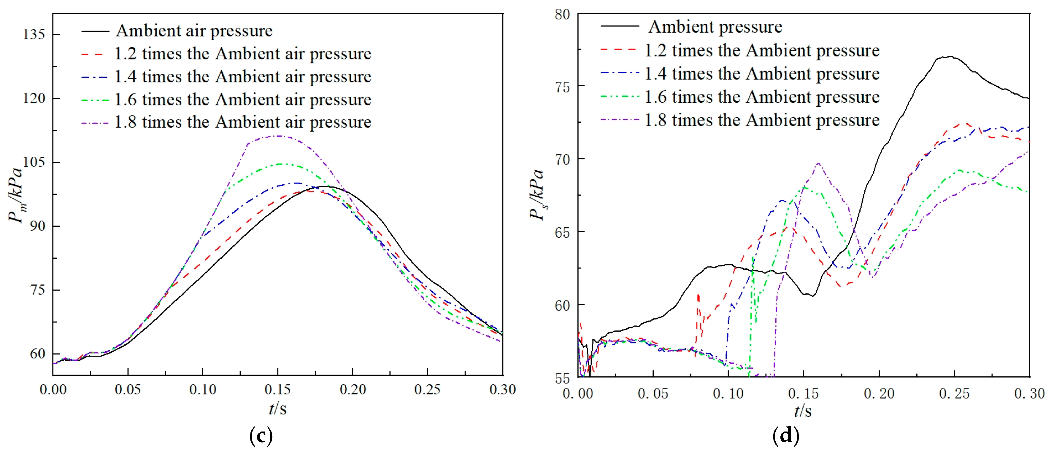
The exhaust pressure of the vent orifice directly influences the maximum pressure of the main airbag and its cushioning performance. For a further analysis of cushioning performance, vent orifice opening pressures of 1, 1.2, 1.4, 1.6, and 1.8 times the ambient pressure were selected. The response results of the airdrop system are shown in Figure 14.
Increasing the exhaust opening pressure delays the airflow. If the vent opens too early, the equipment may collide with the ground, causing a sudden spike in overload. Conversely, if the vent opens too late, the airbag pressure and equipment overload will increase.
As shown in Figure 14, when the exhaust opening pressure is set to 1.2 times the ambient pressure, the airdrop system fails to fully absorb the impact energy, resulting in a hard collision with the ground. Conversely, at 1.8 times the ambient pressure, the main airbag retains excessive energy, leading to an increase in rebound velocity. The optimal cushioning performance is achieved when the exhaust opening pressure is set to 1.6 times the ambient pressure.

4.2. Effect of Vent Orifice Area on Airbag Cushioning Performance

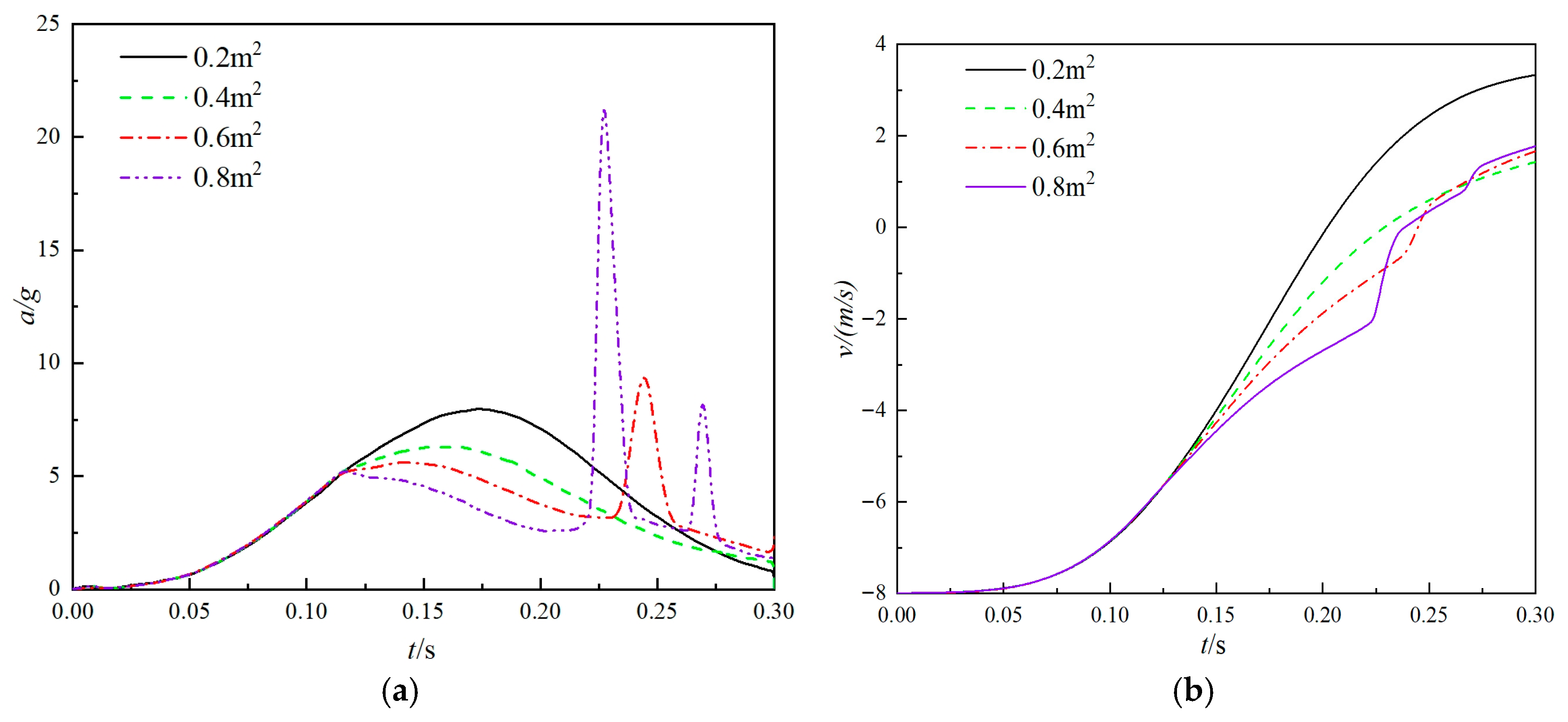
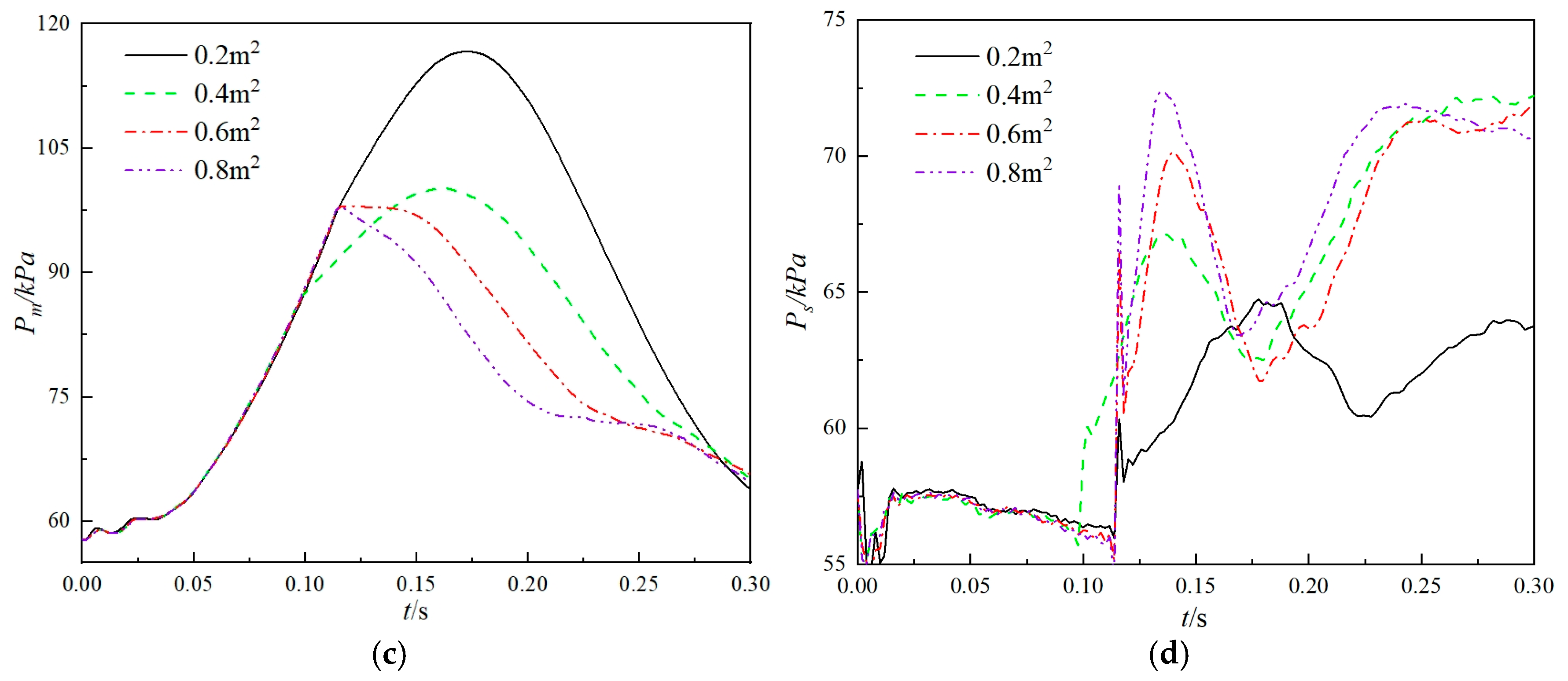
The size of the vent orifice in the new airbag system determines the rate at which gas flows between the main and side airbags. To investigate the effect of the vent orifice area on the cushioning performance, four different total vent hole areas of 0.2 m2, 0.4 m2, 0.6 m2, and 0.8 m2 were selected for comparison. The comparison data are shown in Figure 15.
The vent hole area significantly influences the cushioning performance of the airbag system. An undersized vent orifice restricts airflow, leading to excessive internal pressure in the main airbag and an increase in impact overload. Conversely, an oversized vent orifice facilitates rapid deflation, reducing the system’s ability to absorb impact energy effectively.
Simulation results indicate that when the vent orifice area exceeds 0.2 m2, the main airbag can fully dissipate its stored energy, mitigating the rebound effect of the airdropped equipment. However, when the vent orifice area exceeds 0.4 m2, the risk of hard impact increases due to insufficient cushioning capacity. Therefore, an optimal vent orifice area of 0.4 m2 is recommended to achieve optimal cushioning performance.

4.3. Effect of Main Airbag Height on Airbag Cushioning Performance

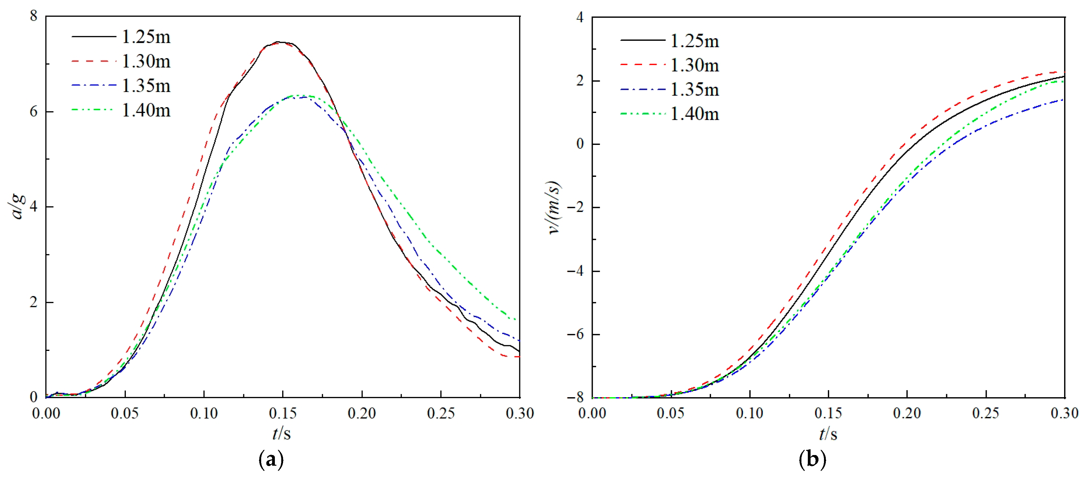
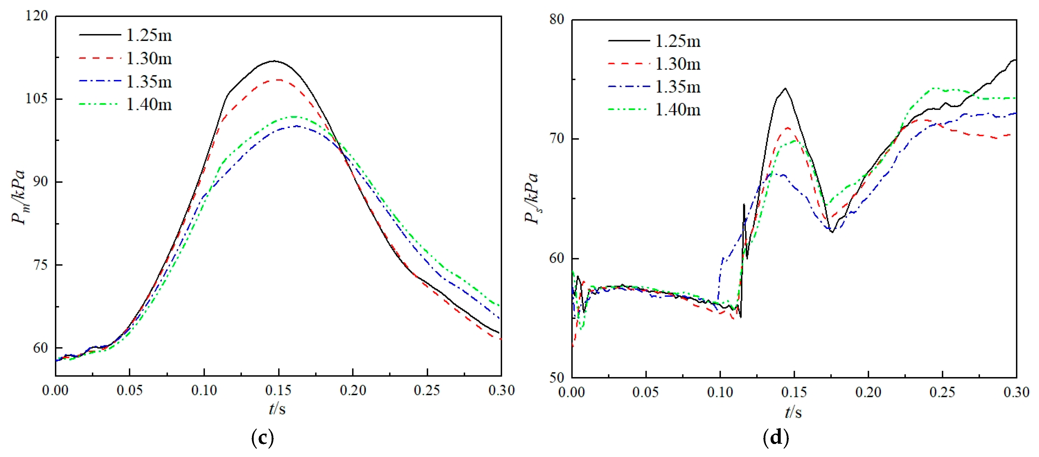
To investigate the effect of the main airbag height on the cushioning performance, four heights of 1.25 m, 1.3 m, 1.35 m, and 1.4 m were selected for comparison. The comparison results are shown in Figure 16.
Based on the appropriate vent orifice opening timing and vent orifice area, the height of the main airbag has a negligible impact on the cushioning performance within an optimal range. As the main airbag height increases, the maximum overload of the airdropped equipment generally decreases. However, when the main airbag height reaches 1.4 m, the rebound velocity of the equipment increases, indicating that an excessively high main airbag can negatively affect landing stability.

4.4. The Influence Trends of Airbag Parameters on the Cushioning Performance

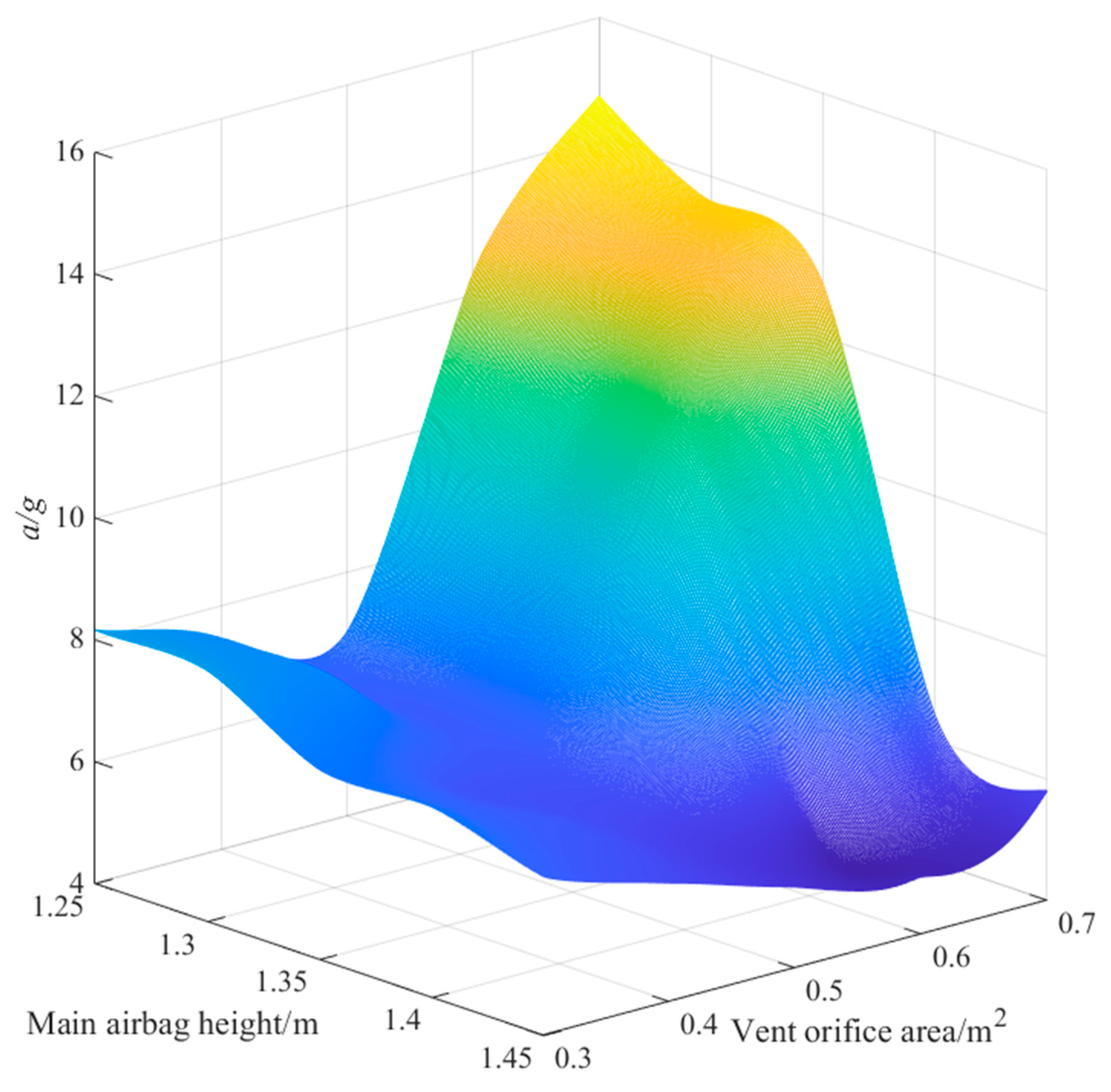
The vent orifice area and the height of the main airbag are the most influential factors affecting the cushioning performance of the airbag system. To systematically evaluate their impact trends, a full-factorial design was employed to generate 25 simulation cases. The corresponding parameter combinations are detailed in Table 3, and the simulation results are presented in Figure 17. The color indicates that the numerical value gradually increases from blue to yellow.
The maximum impact acceleration of airdropped equipment generally decreases with an increase in the height of the main airbag, while it exhibits a non-monotonic trend with respect to vent orifice area—decreasing initially and then rising. This behavior occurs because an excessively large vent orifice area results in rapid gas expulsion, leading to hard impact events. When the airbag height exceeds 1.4 m, the increase in maximum acceleration due to a larger vent orifice area becomes less pronounced. This is attributed to the larger airbag volume, which retains more residual gas after cushioning. However, an excessively high airbag may compromise the lateral stability of the airdropped equipment. Based on the analysis in this study, when the main airbag height is 1.35 m and the vent orifice area is 0.4 m2, the system achieves optimal cushioning performance and landing stability in a 4500 m altitude environment. For practical applications, selecting an appropriate airbag height and vent orifice area based on different environmental conditions is essential to ensure optimal cushioning performance.

5. Evaluation of the Environmental Adaptability of the New Combined Airbag

To further evaluate the cushioning performance of the proposed new combined airbag under diverse working conditions, sampling simulations were conducted for parameters including altitude, ground slope, equipment roll angle, vertical velocity, and horizontal velocity. Surrogate models for the maximum overload, flip angle, and rebound velocity of the airdropped equipment were constructed. The success rate of the equipment during 5000 to 100,000 landing scenarios was calculated via Monte Carlo simulations to comprehensively assess its environmental adaptability.

5.1. Surrogate Model Construction

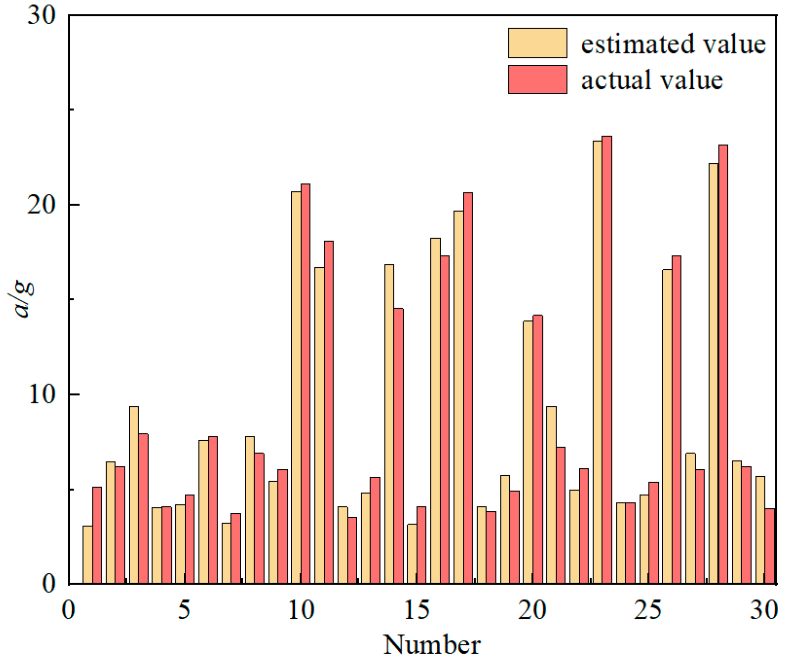
The landing instantaneous velocity, attitude, and ground environment of airdropped equipment at different altitudes significantly influence cushioning responses. Thirty parameter combinations were sampled within each parameter interval using Latin hypercube design, and finite element simulations were performed based on the optimal cushioning structure model selected in the previous section. The sampling ranges and response values are listed in Table 4 [24].
The selection of these condition parameters was determined through actual airdrop testing conducted at a proving ground in China. Statistical analysis of the experimental data yielded the distribution parameters for each operational scenario, with the corresponding distribution functions presented in Table 5.
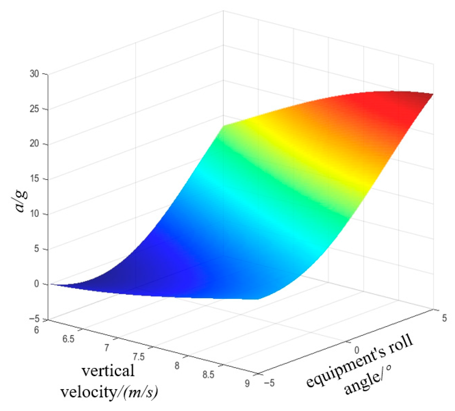
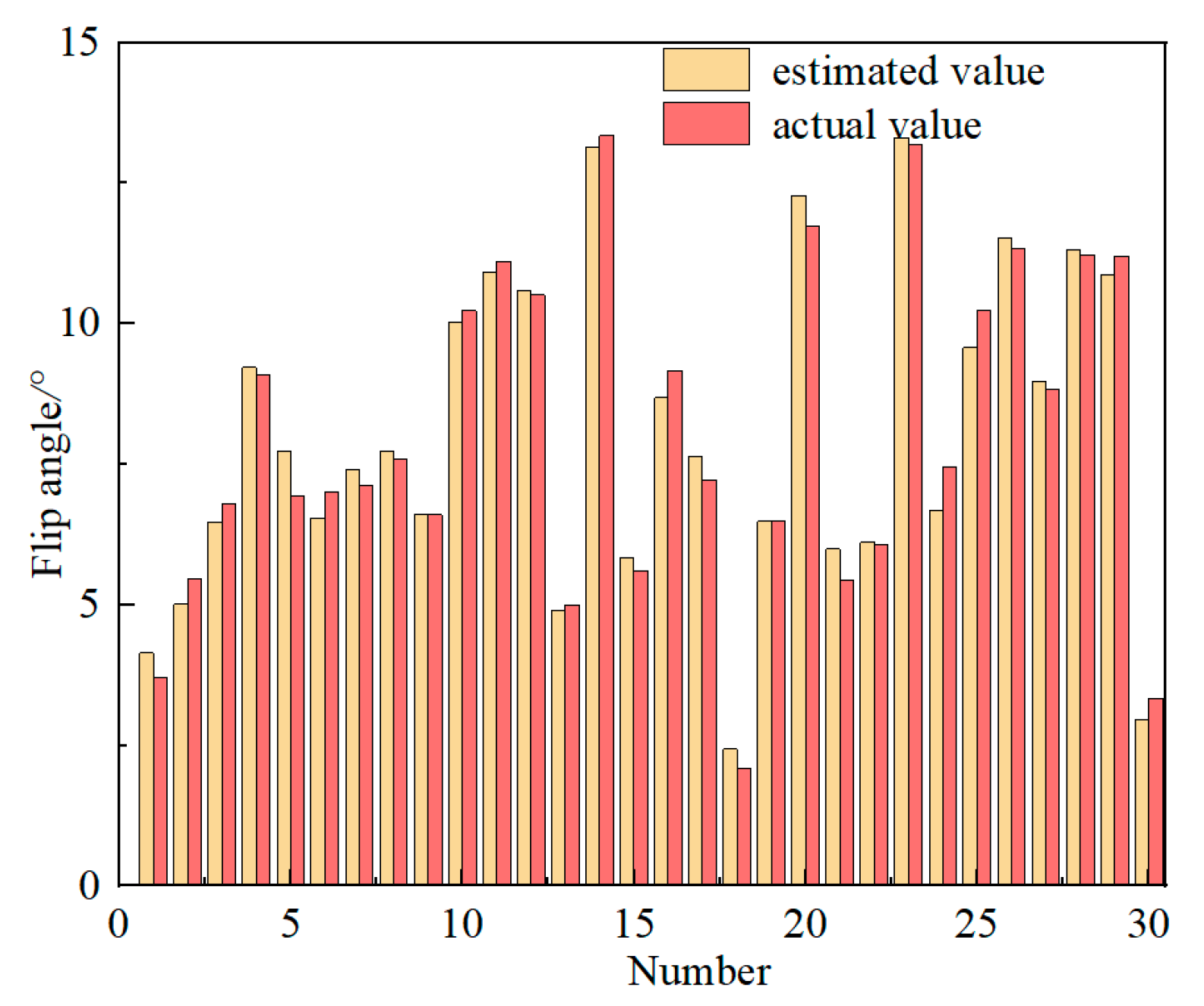
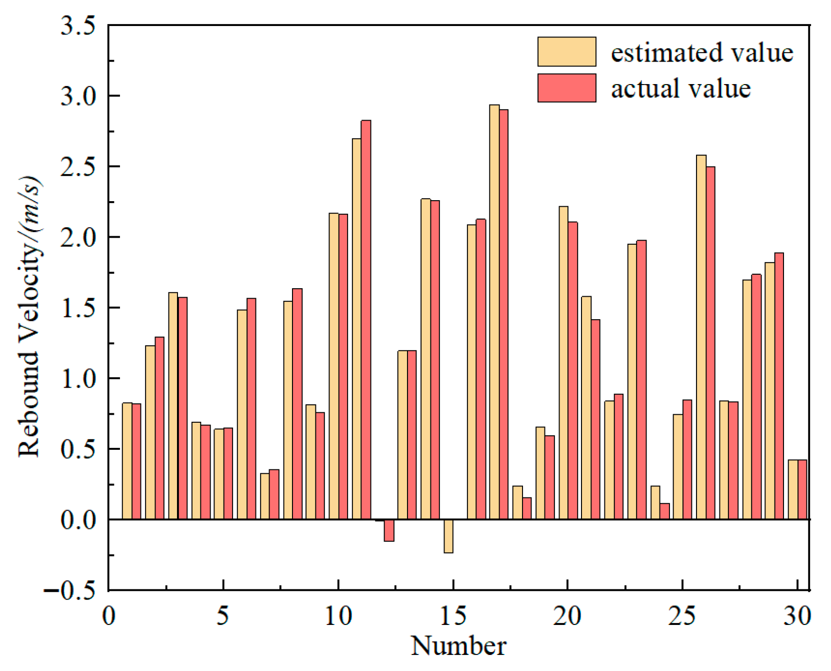
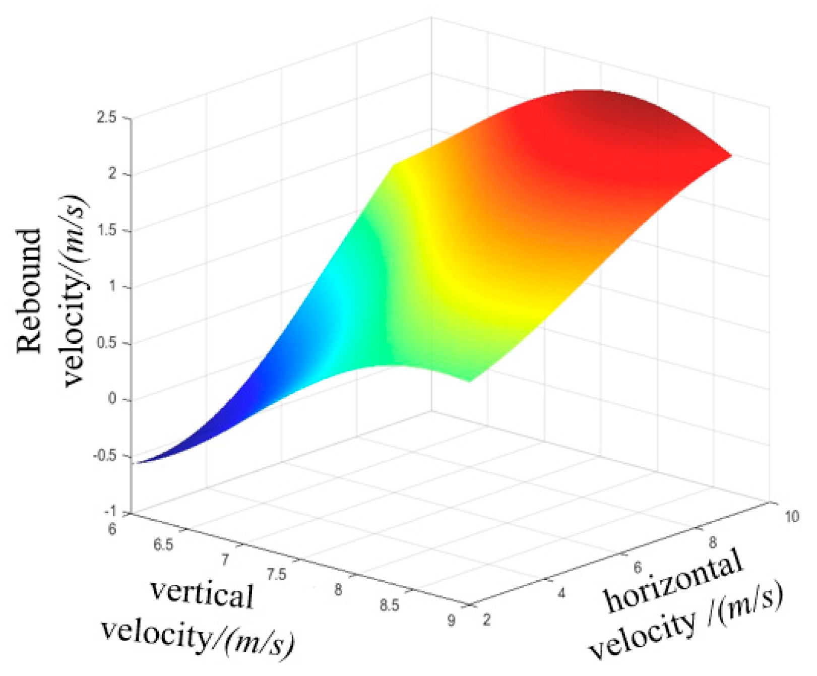
A quadratic polynomial function was used as the fitting function, with the equipment’s maximum overload acceleration, maximum flip angle, and rebound velocity during the cushioning process serving as the objective functions. While concurrently varying two target parameters, all remaining parameters were maintained at constant values throughout the experimental procedure. A surrogate model was constructed accordingly. The fitting results and response surfaces are shown in Figure 18, Figure 19, Figure 20, Figure 21, Figure 22 and Figure 23. The color indicates that the numerical value gradually increases from blue to yellow.
Figure 19 presents the acceleration prediction model. The maximum acceleration of the airdropped equipment increases with the rise in vertical velocity. An increase in the equipment’s roll angle elevates the risk of hard collision on the lateral side during airdropping.
Figure 21 shows the flip angle prediction model. The flip angle of the airdropped equipment is significantly influenced by ground slope: it decreases notably as the ground slope reduces.
Figure 23 illustrates the rebound velocity prediction model. The rebound velocity increases gradually with the rise in vertical velocity, which essentially represents the residual kinetic energy after cushioning energy dissipation. Thus, the vertical and horizontal impact velocities are the primary influencing factors. A moderate rebound of the equipment does not significantly affect the airdropping operation, but the simultaneous occurrence of a large rebound and a high flip angle should be avoided, as otherwise, the risk of equipment rollover will increase.
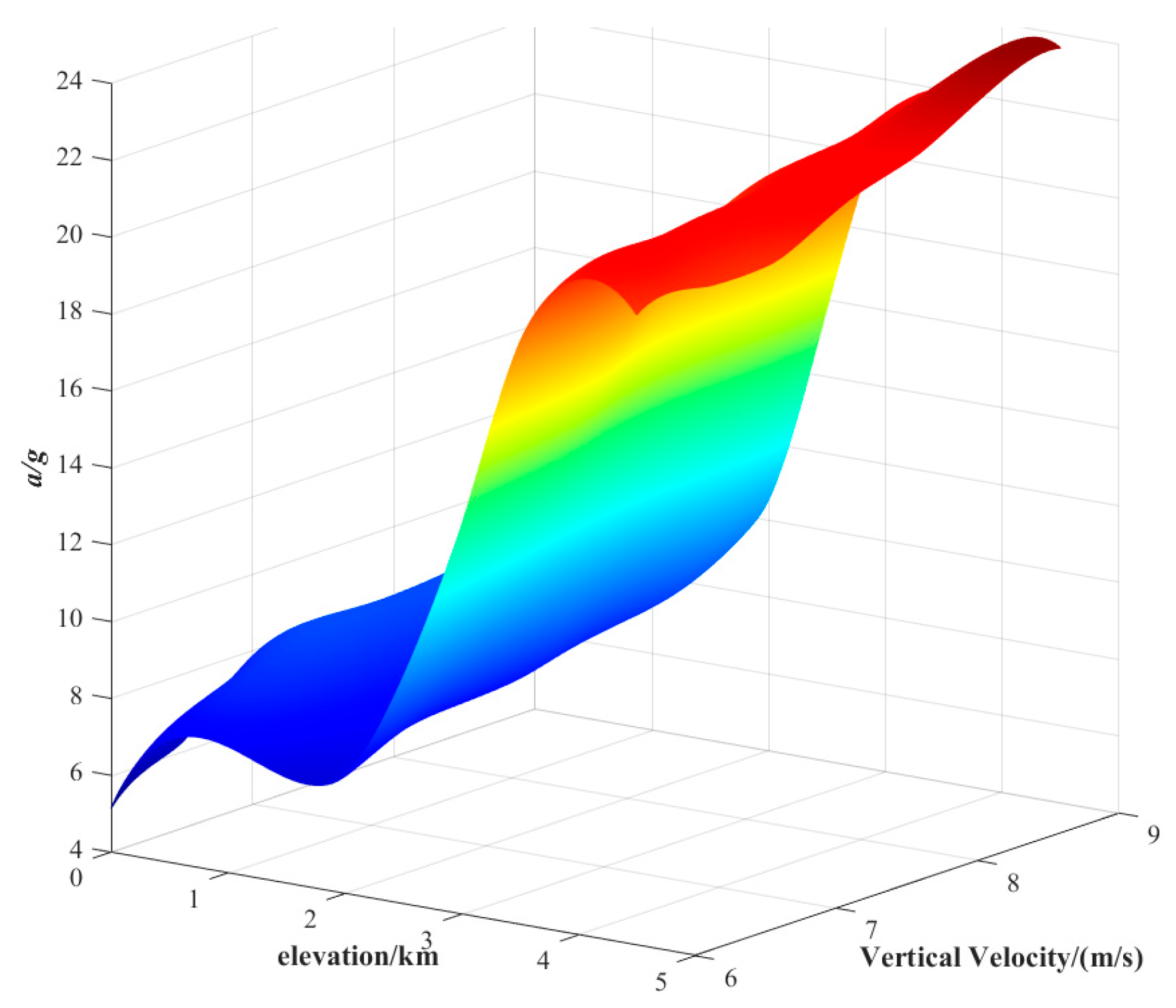
Figure 24 illustrates that the overload of the airdrop equipment increases with rising elevation. When the elevation exceeds 2000 m, the rate of overload growth accelerates. This phenomenon occurs because, as the atmospheric pressure decreases, the airdrop equipment experiences a more intense ground impact upon landing, leading to higher overload. Additionally, at a constant altitude, the peak overload increases with greater vertical velocity.

5.2. Analysis of Airdrop Success Rate and Environmental Adaptability in Complex Environments

To evaluate the landing performance and cushioning reliability of airdropped equipment across diverse environments, Monte Carlo statistical evaluation was employed based on different landing conditions and airdropping environments. Reference [24] presents the indicator thresholds for the cushioning process of large-scale airdropped equipment, as listed in Table 6.
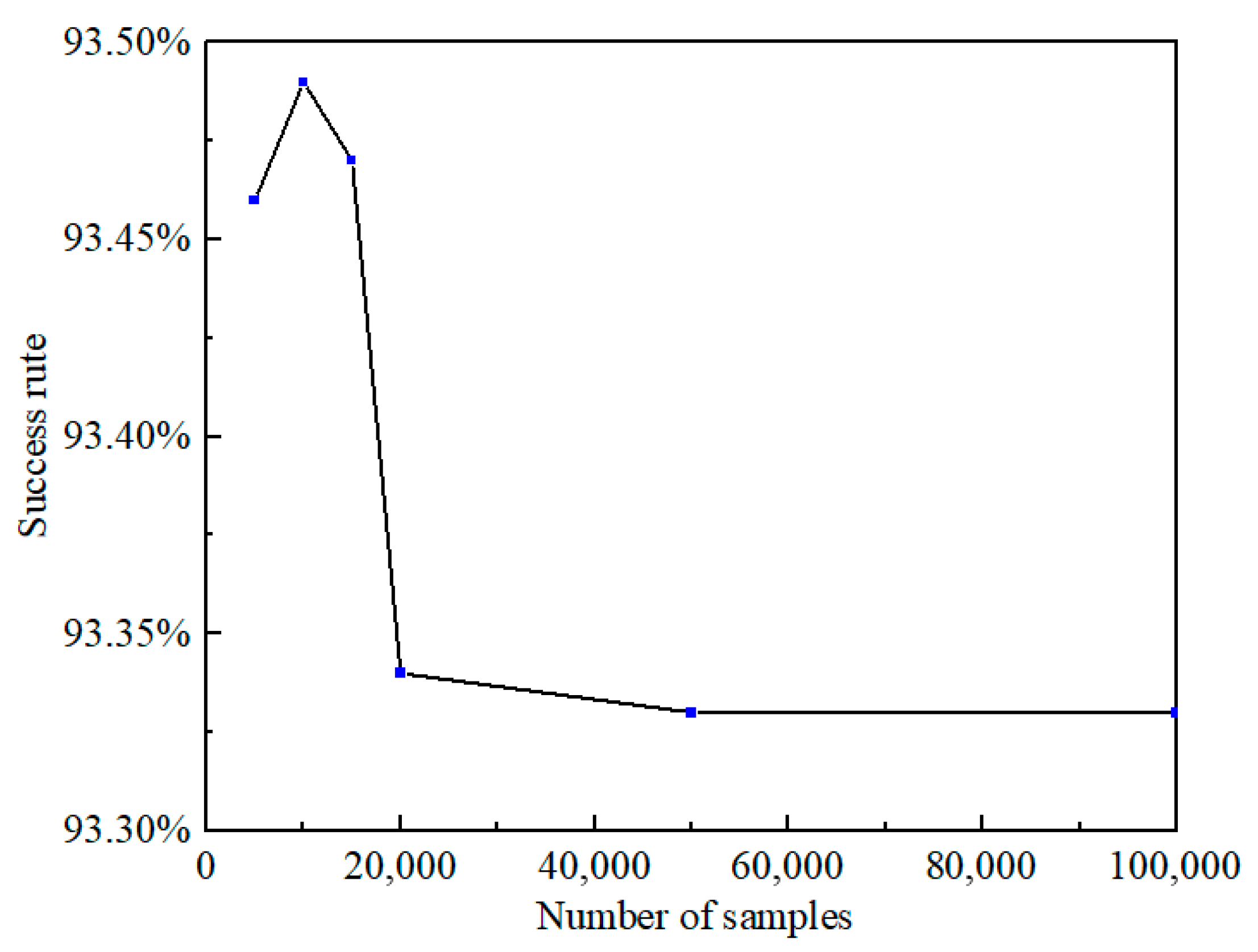
Based on 5000 to 100,000 landing scenarios sampled via Monte Carlo method, Table 7 lists the failure counts caused by various factors, total failure counts, and airdropping success rates. Figure 25 shows the variation in the airdropped equipment’s landing success rate with the number of samples. The success rate gradually stabilizes as the sampling number increases, eventually reaching 93.33%. The primary failure factors are overload acceleration and rebound velocity. Due to complex interactive environments, extreme conditions may still lead to excessively high acceleration from equipment tilting and colliding with the ground or excessively high rebound velocity in areas with sufficient air pressure when gas in the main airbag cannot fully discharge into the side airbag. However, the new combined airbag demonstrates a high airdropping success rate and excellent cushioning performance in high-altitude ranges.

6. Conclusions

This study addresses the challenges of landing heavy airdropped equipment in high-altitude environments with low atmospheric pressure and proposes a combined airbag system for effective landing cushioning. A cylindrical side airbag shape and a folding–deployment scheme were designed. Through simulation comparisons between the traditional airbag and the new combined airbag, the exceptional cushioning performance of the new combined airbag system under high-altitude and low-pressure environments was validated. The new combined airbag system reduced the peak overload by 44.9% and 50%, respectively, under two conditions compared with the traditional airbag. The effects of three key parameters of the combined airbag on cushioning performance were analyzed. As the airbag height increases, the peak overload of the airdropped equipment decreases and the stability decreases. With an increase in orifice area, the peak overload decreases at first and increases later. An excessively large orifice area reduces the effective cushioning time, resulting in hard impacts to the airdropped equipment. When the main airbag height is 1.35 m and the vent orifice area is 0.4 m2, the system achieves optimal cushioning performance and landing stability in a 4500 m altitude environment. The cushioning performance of the airbag under various working conditions was validated through an environmental adaptability assessment. This study provides a reliable solution for landing cushioning of airdropped equipment in harsh high-altitude environments.

Author Contributions

Conceptualization, C.W.; methodology, C.L.; software, Q.Z.; validation, H.W.; formal analysis, J.C.; investigation, C.W.; resources, J.C.; data curation, Q.Z.; writing—original draft preparation, H.W.; writing—review and editing, C.L.; visualization, H.W.; supervision, C.W.; project administration, C.W.; funding acquisition, J.C. All authors have read and agreed to the published version of the manuscript.

Funding

This research was funded by the Young Elite Scientists Sponsorship Program by CAST (2022QNRC001).

Data Availability Statement

The data that support the findings of this study are available from the corresponding author.

Conflicts of Interest

The authors declare that they have no known competing financial interest or personal relationships that could have appeared to influence the work reported in this paper.

References

  1. Liu, X.; Zhang, Z.; Zhao, Z. The uncertain optimisation of buffering characteristics of landing airbag in manned airdrop. Int. J. Crashworthiness 2013, 18, 225–236. [Google Scholar] [CrossRef]
  2. Zhou, X.; Zhou, X.; Li, D.K. Influence of lunar soil parameters on the lunar landing airbag cushioning performance. J. Natl. Univ. Def. Technol. 2022, 44, 69–80. [Google Scholar] [CrossRef]
  3. Lu, C.; Chen, J.; Wang, C.; Song, Z. Landing cushioning analysis of new generation heavy airborne armored vehicles. Aircr. Eng. Aerosp. Technol. 2024, 96, 621–630. [Google Scholar] [CrossRef]
  4. Xu, Y.; Yang, Y.; Huang, H.; Chen, G.; Li, G.; Chen, H. Multi-Objective Optimization Design of an Origami-Inspired Combined Cushion Airbag. Aerospace 2024, 11, 169. [Google Scholar] [CrossRef]
  5. Holnicki-Szulc, J.; Faraj, R.; Graczykowski, C.; Mikułowski, G.; Sekuła, K.; Wiącek, D. Adaptive Airbag Systems for Protection of General Aviation. In Proceedings of the ECCOMAS Thematic Conference on Multidisciplinary Design Optimization of Aerospace Systems, Lisbon, Portugal, 19–21 July 2023. [Google Scholar]
  6. Cole, J.K.; Waye, D.E. A Code for Predicting the Performance of a Gas Bag Impact Attenuation System for the Pathfinder Lander; Sandia National Lab: Albuquerque, NM, USA, 1993. [Google Scholar] [CrossRef]
  7. Esgar, J.B.; Morgan, W.C. Analytical Study of Soft Landing on Gasfilled Bags; Lewis Research Center: Cleveland, OH, USA, 1960. [Google Scholar]
  8. Zhou, X.; Zhou, S.M.; Li, D.K. Research on design and cushioning performance of combined lunar landing airbag. Acta Astronaut. 2022, 191, 55–78. [Google Scholar] [CrossRef]
  9. Cao, P.; Hou, X.Y.; Wang, Y.B. Flexible airbag cushioning for Martian landing based on discrete element method. Adv. Space Res. 2019, 63, 2566–2583. [Google Scholar] [CrossRef]
  10. Yin, H.; Wen, G. Multi-objective optimisation design of a double-chamber airbag landing system with structure-selection techniques. Int. J. Crashworthiness 2012, 17, 529–539. [Google Scholar] [CrossRef]
  11. Hong, H.J.; Wang, H.Y.; Li, J.Y. Research on assessment method of airbag cushion system for airdropping equipment. J. Mech. Eng. 2015, 51, 148–154. [Google Scholar] [CrossRef]
  12. Fu, X.H.; Wang, J.; Chen, Y. A study on soft landing buffering process of manned armored vehicle airdrop. J. Vib. Shock 2021, 40, 57–64. [Google Scholar] [CrossRef]
  13. Dai, J.C.; Zhou, Y.B.; Zhang, J.C. Effects of different postures on crew damage under the impact of manned airdrop landing. Explos. Shock Waves 2021, 41, 122–134. [Google Scholar] [CrossRef]
  14. Tang, X.H.; Qin, L.F.; Tang, J.H. Stability analysis of a soft landing system for heavy cargo airdrop. J. Vib. Shock 2015, 34, 122–126. [Google Scholar] [CrossRef]
  15. Li, J. Exhaust Area Matching Method of Self-Inflating Airbag Dropped at High Altitude. J. Ordnance Equip. Eng. 2019, 40, 21–24. [Google Scholar] [CrossRef]
  16. Lee, C.; Rosato, N.; Lai, F. An investigation of improved airbag performance by vent control and gas injection. In Proceedings of the 11th Aerodynamic Decelerator Systems Technology Conference, San Diego, CA, USA, 9–11 April 1991; Available online: https://arc.aiaa.org/doi/pdf/10.2514/6.1991-892 (accessed on 2 July 2025).
  17. Timmers, R.; Hardy, R.; Welch, J. Modeling and simulation of the second generation Orion Crew Module air bag landing system. In Proceedings of the 20th AIAA Aerodynamic Decelerator Systems Technology Conference and Seminar, Seattle, WA, USA, 4–7 May 2009; Available online: https://arc.aiaa.org/doi/pdf/10.2514/6.2009-2921 (accessed on 1 July 2025).
  18. Tutt, B.; Sandy, C.; Corliss, J. Status of the Development of an Airbag Landing System for the Orion Crew Module. In Proceedings of the 20th AIAA Aerodynamic Decelerator Systems Technology Conference and Seminar, Seattle, WA, USA, 4–7 May 2009; Available online: https://arc.aiaa.org/doi/pdf/10.2514/6.2009-2923 (accessed on 6 July 2025).
  19. Wang, H.Y.; Hong, H.J.; Li, J.Y.; Rui, Q. Study on multi-objective optimization of airbag landing attenuation system for heavy airdrop. Def. Technol. 2013, 9, 237–241. [Google Scholar] [CrossRef]
  20. Do, S.; De Weck, O. A personal airbag system for the orion crew exploration Vehicle. Acta Astronaut. 2012, 81, 239–255. [Google Scholar] [CrossRef]
  21. Alizadeh, M.; Sedaghat, A.; Kargar, E. Shape and orifice optimization of airbag systems for UAV parachute landing. Int. J. Aeronaut. Space Sci. 2014, 15, 335–343. [Google Scholar] [CrossRef]
  22. Wang, H.Y.; Wang, C.; Lu, C.Y. Multi Objective Optimization and Design of Reinstalling Airdrop Buffer System. Spacecr. Recovery Remote Sens. 2025, 46, 1–10. [Google Scholar]
  23. Xiao, X.; Long, A.; Lin, H. Large deformation modelling of tight woven fabric under high air pressure. J. Eng. Fibers Fabr. 2015, 10, 10–11. [Google Scholar] [CrossRef]
  24. Wang, H.Y. Optimization and Environmental Adaptability Evaluation of Airbag Landing Attenuation System for Airdrop; National Defense Industry Press: Arlington, VA, USA, 2016; ISBN 9787118106398. [Google Scholar]
Figure 1. Airbag system: (a) traditional airbag system; (b) new combined airbag system.
Aerospace 12 00768 g001
Figure 2. Schematic of the cushioning process for the new combined airbag system.
Aerospace 12 00768 g002
Figure 3. Schematic of airbag folding. (a)Before folding; (b)after folding.
Aerospace 12 00768 g003
Figure 4. Side airbag inflation process.
Aerospace 12 00768 g004
Figure 5. Finite element model of the new combined airbag cushioning system for airdropped equipment.
Aerospace 12 00768 g005
Figure 6. Buffering process.
Aerospace 12 00768 g006
Figure 7. Comparison of three different mesh sizes.
Aerospace 12 00768 g007
Figure 8. Two conditions.
Aerospace 12 00768 g008
Figure 9. Equipment acceleration of condition 1.
Aerospace 12 00768 g009
Figure 10. Equipment velocity of condition 1.
Aerospace 12 00768 g010
Figure 11. Equipment acceleration of condition 2.
Aerospace 12 00768 g011
Figure 12. Equipment velocity of condition 2.
Aerospace 12 00768 g012
Figure 13. Cushioning airbags’ support effect.
Aerospace 12 00768 g013
Figure 14. Effect of vent orifice exhaust pressure. (a) Equipment acceleration; (b) equipment velocity; (c) main airbag pressure; (d) side airbag pressure.
Aerospace 12 00768 g014aAerospace 12 00768 g014b
Figure 15. Effect of vent orifice area. (a) Equipment acceleration; (b) equipment velocity; (c) main airbag pressure; (d) side airbag pressure.
Aerospace 12 00768 g015aAerospace 12 00768 g015b
Figure 16. Effect of main airbag height. (a) Equipment acceleration; (b) equipment velocity; (c) main airbag pressure; (d) side airbag pressure.
Aerospace 12 00768 g016aAerospace 12 00768 g016b
Figure 17. The influence of main airbag height and vent orifice area on the peak acceleration during the cushioning process.
Aerospace 12 00768 g017
Figure 18. Acceleration prediction model (R2 = 0.975).
Aerospace 12 00768 g018
Figure 19. Acceleration response surface model.
Aerospace 12 00768 g019
Figure 20. Flip angle prediction model (R2 = 0.983).
Aerospace 12 00768 g020
Figure 21. Flip angle response surface model.
Aerospace 12 00768 g021
Figure 22. Rebound velocity prediction model (R2 = 0.99).
Aerospace 12 00768 g022
Figure 23. Rebound velocity response surface model.
Aerospace 12 00768 g023
Figure 24. The influence of elevation and vertical velocity on the peak acceleration during the cushioning process.
Aerospace 12 00768 g024
Figure 25. The success rate of airdrops.
Aerospace 12 00768 g025
Table 1. Finite element model parameters and settings.
NumberParametersValues
1Equipment mass15 t
2Initial pressure5.7715 × 104 Pa
3Landing velocity8 m/s
4Main airbag height1.35 m
5Vent orifice area0.04 m2
6Airbag fabric elastic modulus4 × 108 Pa
7Airbag fabric density850 Kg/m3
8Airbag fabric Poisson’s ratio0.3
9Equipment and airbag elementShell
10Equipment material density7850 Kg/m3
11Number of nodes194,073
12Number of elements195,177
13Software of finite element analysislsdyna_R11
Table 2. Parameters for the two conditions.
ConditionVertical Velocity (m/s)Lateral Velocity (m/s)Tilt Angle/°Ambient Atmospheric Pressure/Pa
180057,715
285557,715
Table 3. Table of airbag parameters.
NumberAirbag Height/mVent Orifice Area/m2a/g
11.250.38.163
21.250.47.475
31.250.57.022
41.250.612.34
51.250.714.7
61.300.38.120
71.300.47.440
81.300.56.674
91.300.610.612
101.300.713.21
111.350.37.122
121.350.46.314
131.350.56.7
141.350.610.5
151.350.712.85
161.400.37.130
171.400.46.35
181.400.55.755
191.400.65.32
201.400.76.4
211.450.36.610
221.450.45.95
231.450.55.33
241.450.64.94
251.450.75.8
Table 4. Parameters of the landing situation for the airdropped equipment.
NumberParameterData Range
1Horizontal velocity/(m·s−1)[2, 9]
2Vertical velocity/(m·s−1)[6, 9]
3Elevation/m[0, 4500]
4Roll angle/°[−5, 5]
5Ground slope/°[−5, 5]
Table 5. Distribution function table of parameters.
NumberParameterDistribution FunctionData
1Lateral velocityWeibull distribution α = 2.9β = 6.3
2Vertical velocityNormal distribution
μ = 7.1
σ = 0.6
3Roll angleNormal distribution
μ = 7.1
σ = 2.33
4Ground slopeUniform distributiona = −5, b = 5
Table 6. Failure threshold values of airdrop equipment.
Response Evaluation Indicators of Airdrop EquipmentFailure Threshold Value
Maximum overload acceleration of equipment/g20
Maximum flip angle of equipment/°25
Maximum rebound velocity of equipment/(m·s−1)3
Table 7. Success rate statistics.
Number of Failures
Number of Samples Number of Failures Number of FailuresSuccess Rate Statistics
Maximum Overload Acceleration/gMaximum Flip Angle/°Maximum Rebound Velocity of Equipment/(m·s−1)
5000232513032793.46%
10,000459625765193.49%
15,0006861437497993.47%
20,00096012482133293.34%
50,0002342301261333593.33%
100,0004735842513667093.33%
Disclaimer/Publisher’s Note: The statements, opinions and data contained in all publications are solely those of the individual author(s) and contributor(s) and not of MDPI and/or the editor(s). MDPI and/or the editor(s) disclaim responsibility for any injury to people or property resulting from any ideas, methods, instructions or products referred to in the content.