This subsection presents and discusses the acoustic measurements obtained for the three propeller configurations and the two experimental setups introduced earlier (with setup #2 applied exclusively to the isolated rotor test case).
3.2.1. Isolated Propeller
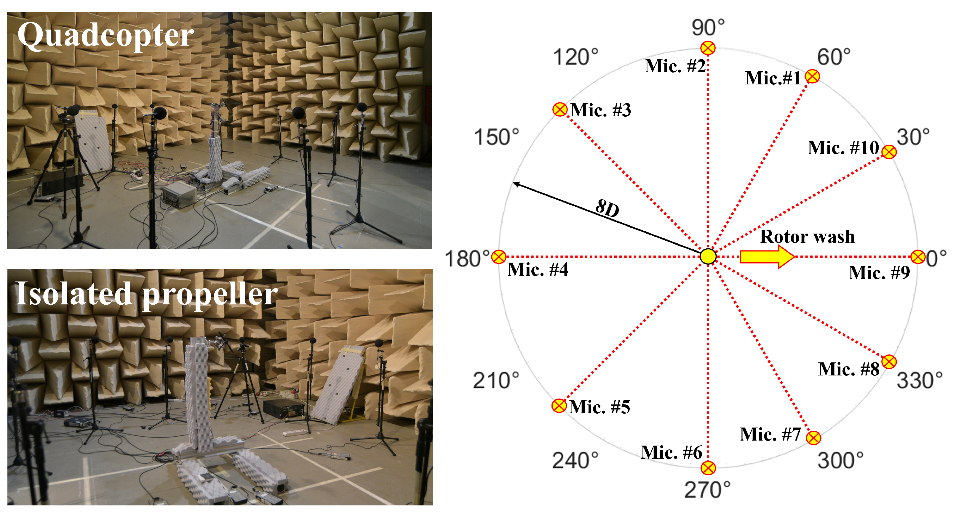
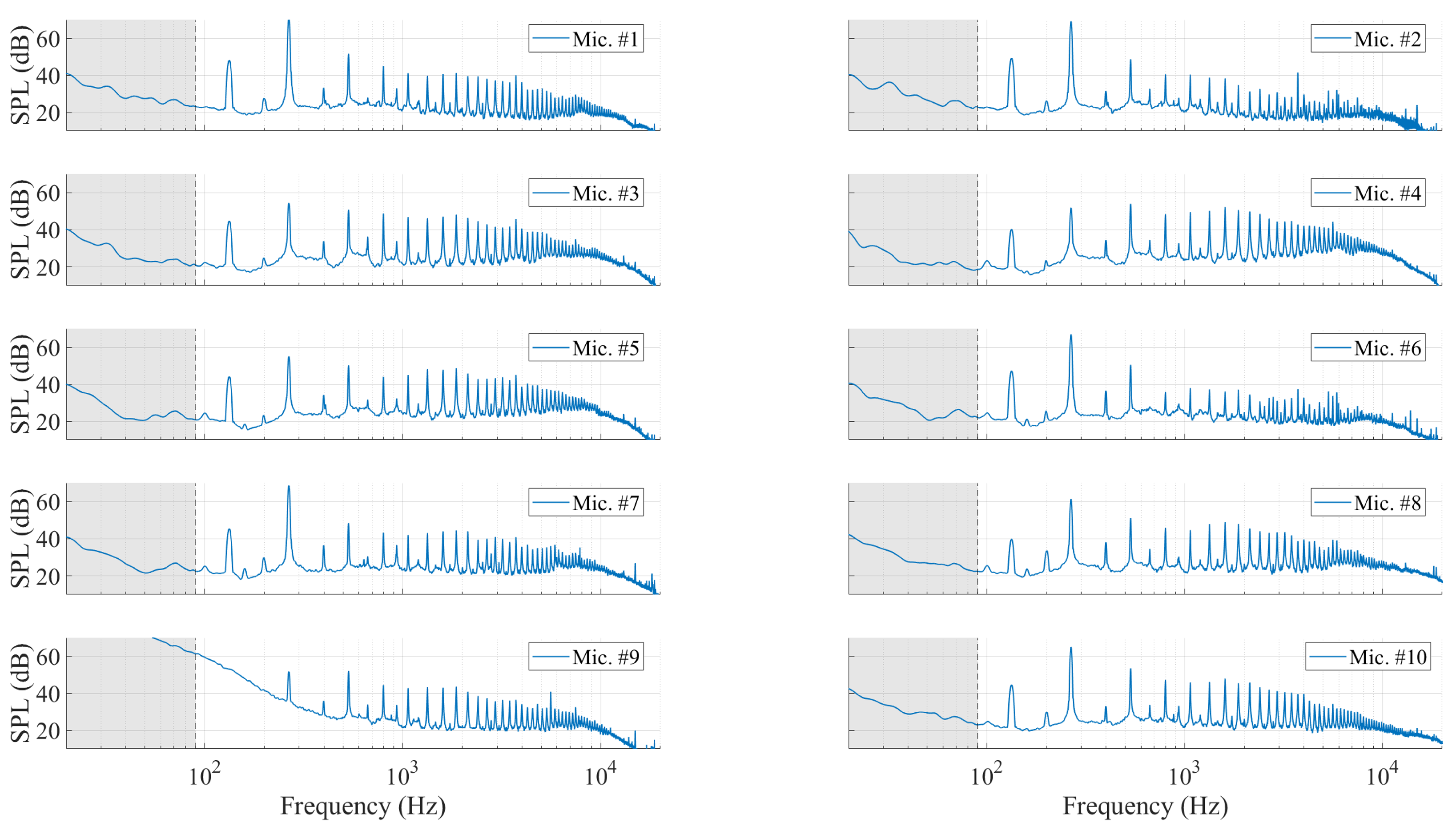
Figure 9 presents the noise spectra obtained from ten microphones deployed at various azimuth angles around a full 360° circle (refer to
Figure 6). The data represent the acoustic emissions from an isolated propeller operating at 8000 rpm, rotating counter-clockwise (CCW) with a two-blade configuration (Type-1). The sound pressure level (SPL) spectra are provided without any weighting functions to accurately represent the raw acoustic energy distribution across frequencies and to explain the underlying noise generation mechanisms.
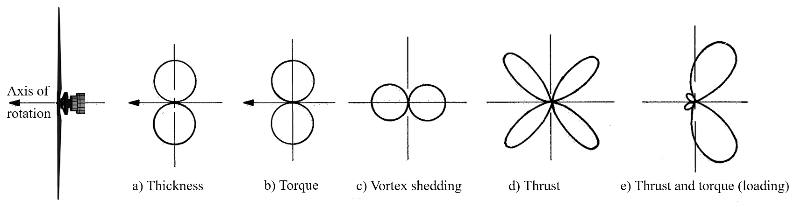
A feature of the spectra is the distinct tonal peaks at integer multiples of the fundamental blade passing frequency (BPF). For a two-bladed rotor at 8000 rpm (approximately 133 rps), the BPF is calculated as 2 × 133 ≈ 266 Hz. The amplitude of the BPF and its harmonics varies among the microphones, which can be attributed to the directional characteristics of rotor noise. As discussed in the introduction, rotor noise typically exhibits pronounced directivity lobes at specific azimuth angles and elevations, depending by factors such as thickness and loading noise. The dominant tonal component corresponds to the fundamental BPF, with its harmonics reaching levels up to 30–50 dB above the broadband noise. In particular, the observed almost 20 dB difference between the first and second harmonics underscores the significant contribution of the fundamental BPF to the overall sound pressure level (OASPL). In addition to the tonal components, a broadband noise contribution is evident beneath and between the tonal peaks. This broadband noise, which spans the entire frequency range, is associated with turbulence-related mechanisms. It is also noteworthy that microphone 9 was positioned directly within the rotor’s downwash, exposing it to intense, large-scale turbulent structures that amplified the low-frequency broadband noise. Furthermore, additional tones appear in the spectra that cannot be directly attributed to rotor noise (for example, the tone at 133 Hz and the peak at 200 Hz), necessitating a deeper investigation. This analysis involved recording noise with the rotor decoupled and comparing the results to those obtained under loaded conditions at a fixed rpm. Specifically,
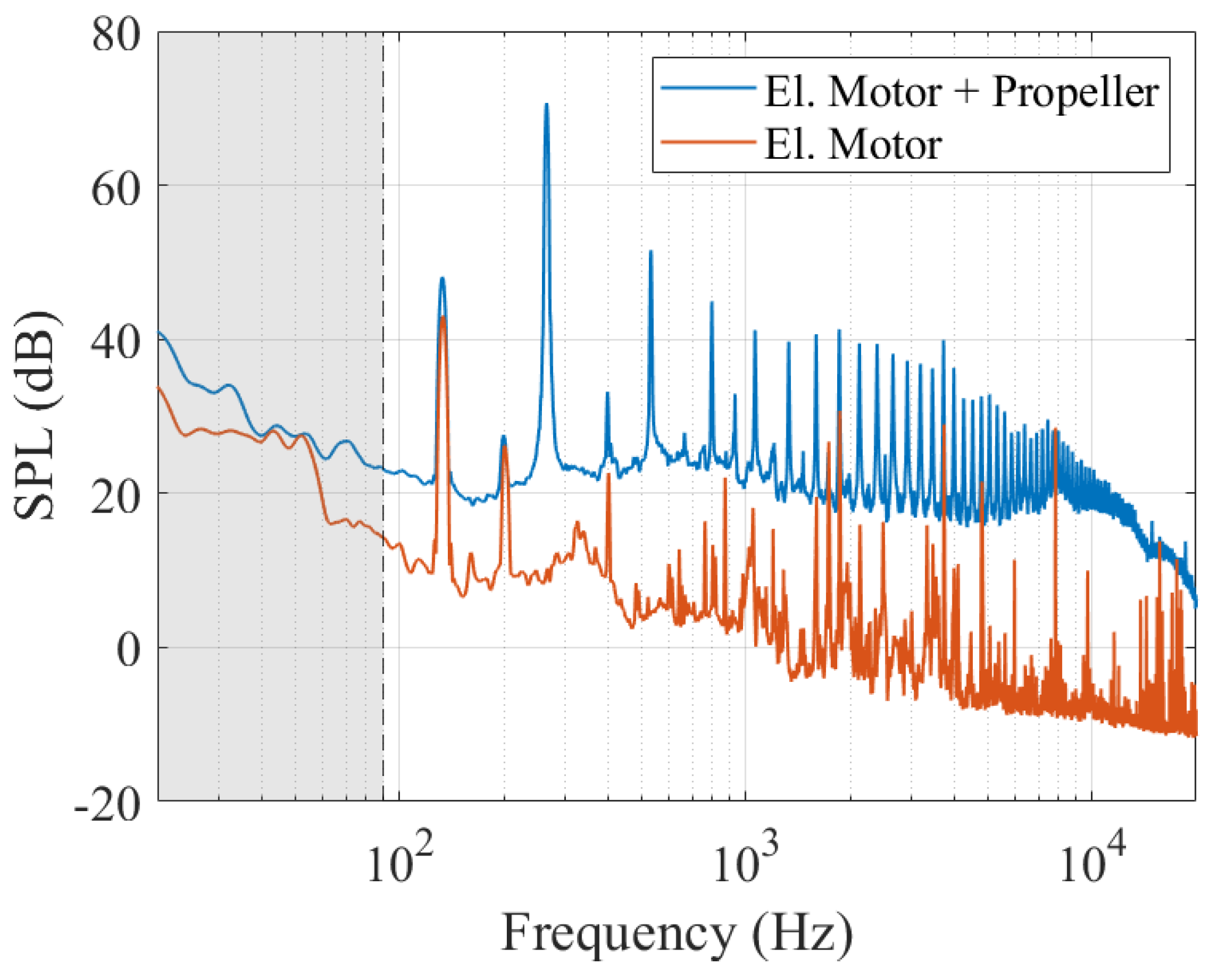
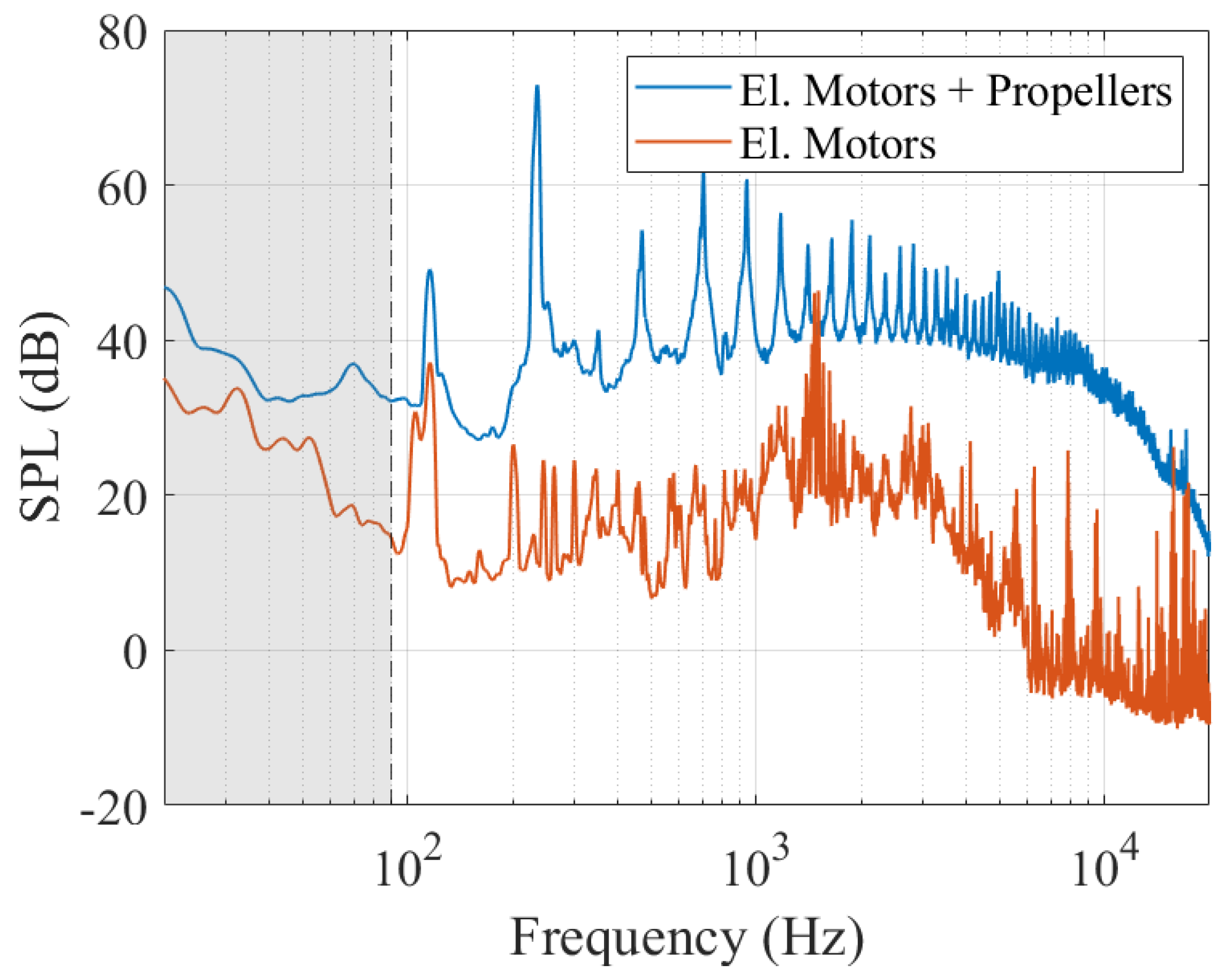
Figure 10 presents a comparative analysis of the narrowband noise spectra for the isolated rotor and the isolated electric motor operating at the maximum tested speed of 8000 rpm, as measured by microphone 1 (refer to setup #1 in
Figure 6).
Further analysis reveals that the electric motor itself emits tonal noise [
26], a phenomenon that becomes more pronounced when the motor is coupled with the rotor. This increase in noise levels is attributed to an enhanced stator magnetic flux density resulting from higher current draw under loads. As illustrated in
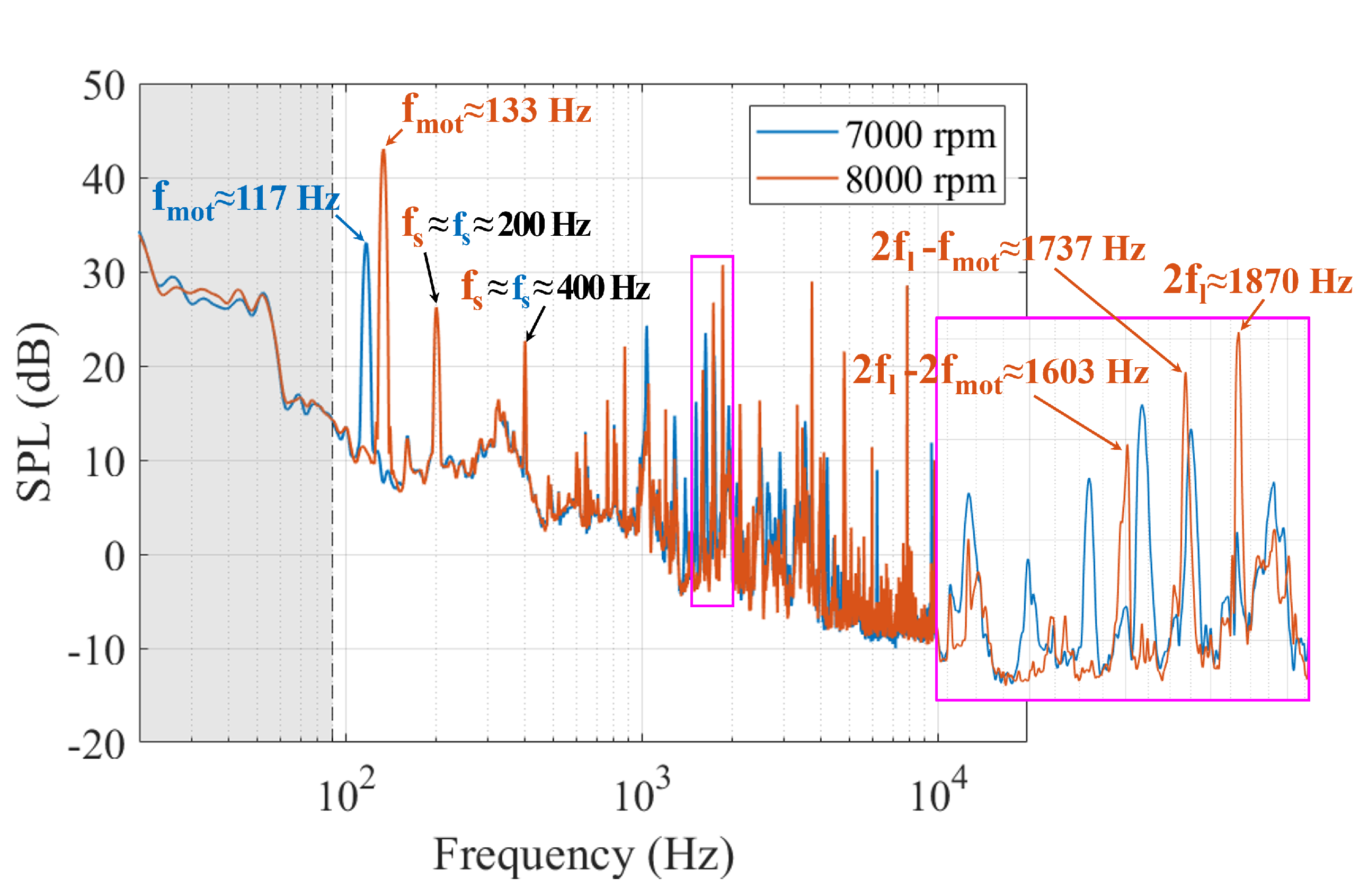
Figure 11, the motor’s noise spectrum exhibits a distinct peak corresponding to its rotational speed, calculated as
. At 8000 rpm, this fundamental frequency is approximately 133 Hz. Moreover, spectral analysis revealed prominent peaks at integer multiples of the supply current’s fundamental line frequency, expressed as
, where
N represents the number of pole pairs. These peaks arise from the combined effects of the rotor and stator magnetic fields. For the tested 7-pole motor operating at 133 Hz, one of the resulting electromagnetic frequencies was observed at approx. 1870 Hz [
26]. In addition, the data indicate the presence of dynamic rotor eccentricity, as evidenced by frequency side lobes at offsets of ±
(
q is an integer) from the electromagnetic frequency. In this test case, a side lobe at 1737 Hz (i.e., 1870 Hz–133 Hz) was detected. Finally, tests conducted at 7000 rpm revealed that while some spectral peaks shift in frequency with motor speed, others remain nearly fixed, suggesting that the invariant peaks are likely associated with structural resonances
within the motor and its mounting system.
Figure 12 and
Figure 13 present the resulting overall sound pressure levels (OASPL). The rotor axis is aligned along the 180°–0° direction, with the wake pointing towards 0°. Two experimental constraints must be considered when interpreting these data. First, the ground was treated as an acoustically rigid surface, so local reflections could either reinforce or attenuate the radiated sound, thereby altering the apparent directivity. Second, there is a small but significant mounting asymmetry: although the rotor hub is centred, the pylon supporting the isolated propeller is offset to the left side of the array (the 0°–180° hemisphere), roughly in line with the 30° microphone. That lateral offset produces additional shading behind the propeller and contributes to the left-right level differences observed in the OASPL profiles. As discussed in the preceding section, the OASPL was obtained by integrating the acoustic spectrum from 90 Hz to 20 kHz. Because microphone 9 lies within the propeller wake, it registers substantial low-frequency energy (
Figure 9), making its OASPL highly sensitive to the lower integration bound. Its data were therefore omitted from the OASPL plots, although the measurement is retained in the tonal directivity figures since BPF and its harmonics rise distinctly above the broadband noise. Moreover, although electric motor noise is not the focus of this study, at every rotational speed and microphone position, the fundamental motor tone remains at least 20 dB below the BPF (
Figure 10). Therefore, even though this component was retained in the OASPL calculation, it does weakly raise the overall level by no more than 0.004 dB.
A comparative evaluation of the azimuthal OASPL distributions obtained with the Type-1 and Type-2 propellers indicates negligible spatial variability over the full rotational speed range considered. Across 3000–8000 rpm, the mean absolute level difference recorded by the ten-microphone array remained below 0.6 dB, with a standard deviation (SD) under 0.5 dB, except at 5000 rpm, where the mean difference reached roughly 2 dB and the SD 0.8 dB. Such minor discrepancies almost certainly fall within the combined experimental uncertainty rather than reflecting systematic geometric differences between the blade sets. However, the close agreement between data acquired in separate, independent test sessions can be regarded as a confirmation of the repeatability and overall fidelity of the measurements. Further experiments performed with opposite senses of rotation (CW versus CCW) reveal far larger azimuthal variations than those observed when only the blade was changed. Over the low-moderate speed range (3000–5000 rpm), the mean absolute OASPL difference among the ten microphones already reaches 1 dB. At higher rotational rates, the disparity increases sharply: about 3 dB at 6000 rpm and 3–4 dB in the 7000–8000 rpm range. The associated standard deviation grows from roughly 1 dB at the lowest speed to nearly 4 dB at 7000 rpm, highlighting the substantial microphone-to-microphone scatter induced by the change in rotation sense. The directivity patterns clarify the origin of this behaviour. The support pylon lies directly on the acoustic line of sight of microphone 10, producing shielding and a corresponding level reduction relative to its mirrored counterpart, namely microphone 8. Comparable shielding has been reported in the literature, where a short barrier positioned near an open rotor produced up to 8.5 dB of attenuation at certain directivity angles [
9]. In the present tests, this effect is most pronounced for clockwise rotation, whereas, when the rotor spins counter-clockwise, the attenuation at the same azimuth is markedly smaller, presumably because the ground reflection path is altered differently for the two senses of rotation. Overall, these findings demonstrate that rotation sense can dominate the apparent non-uniformity of the acoustic field whenever structural or environmental asymmetries are present. The observed deviations, which reach up to 4 dB, exceed the experimental uncertainty by a wide margin, confirming that the effect is physical rather than a measurement artefact.
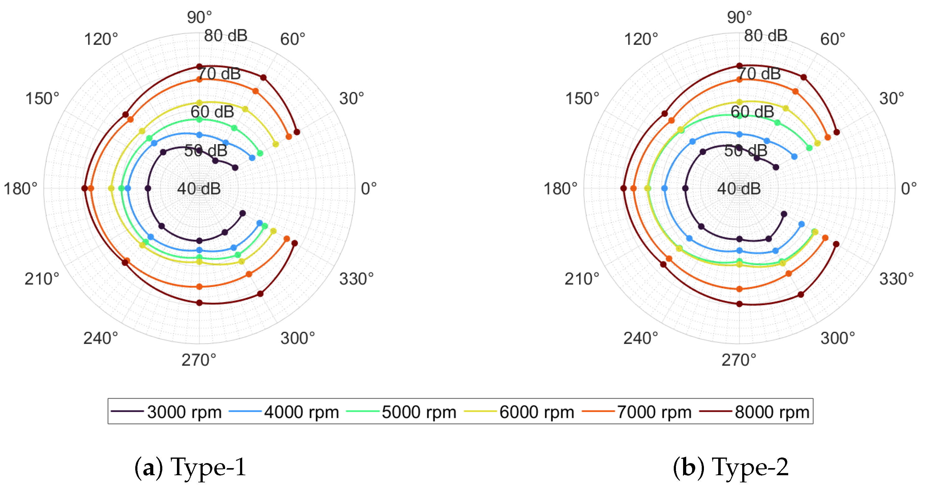
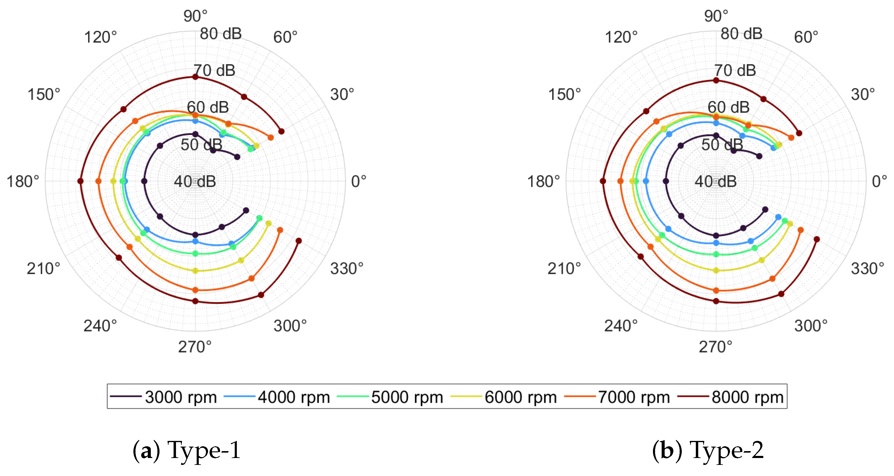
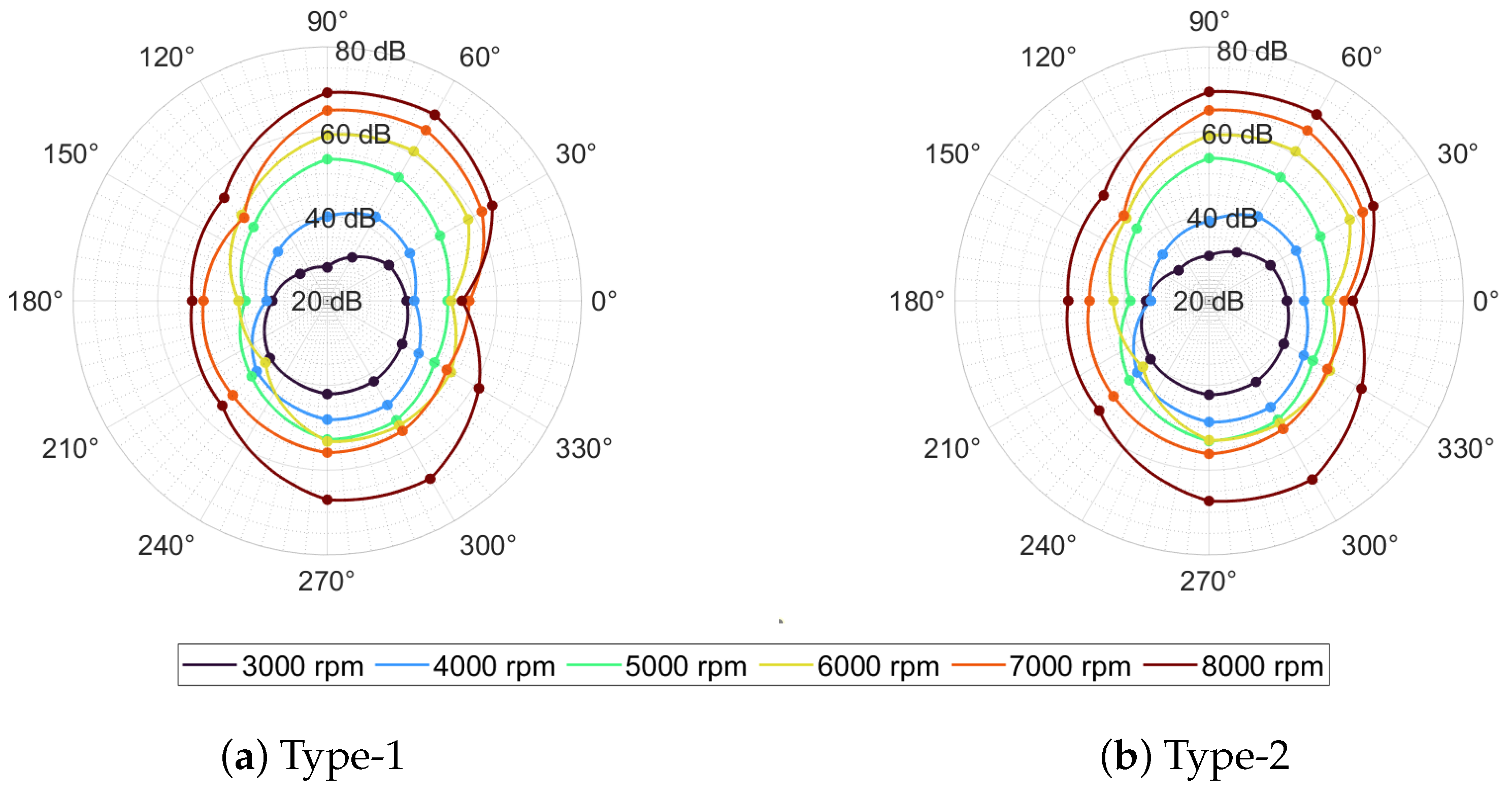
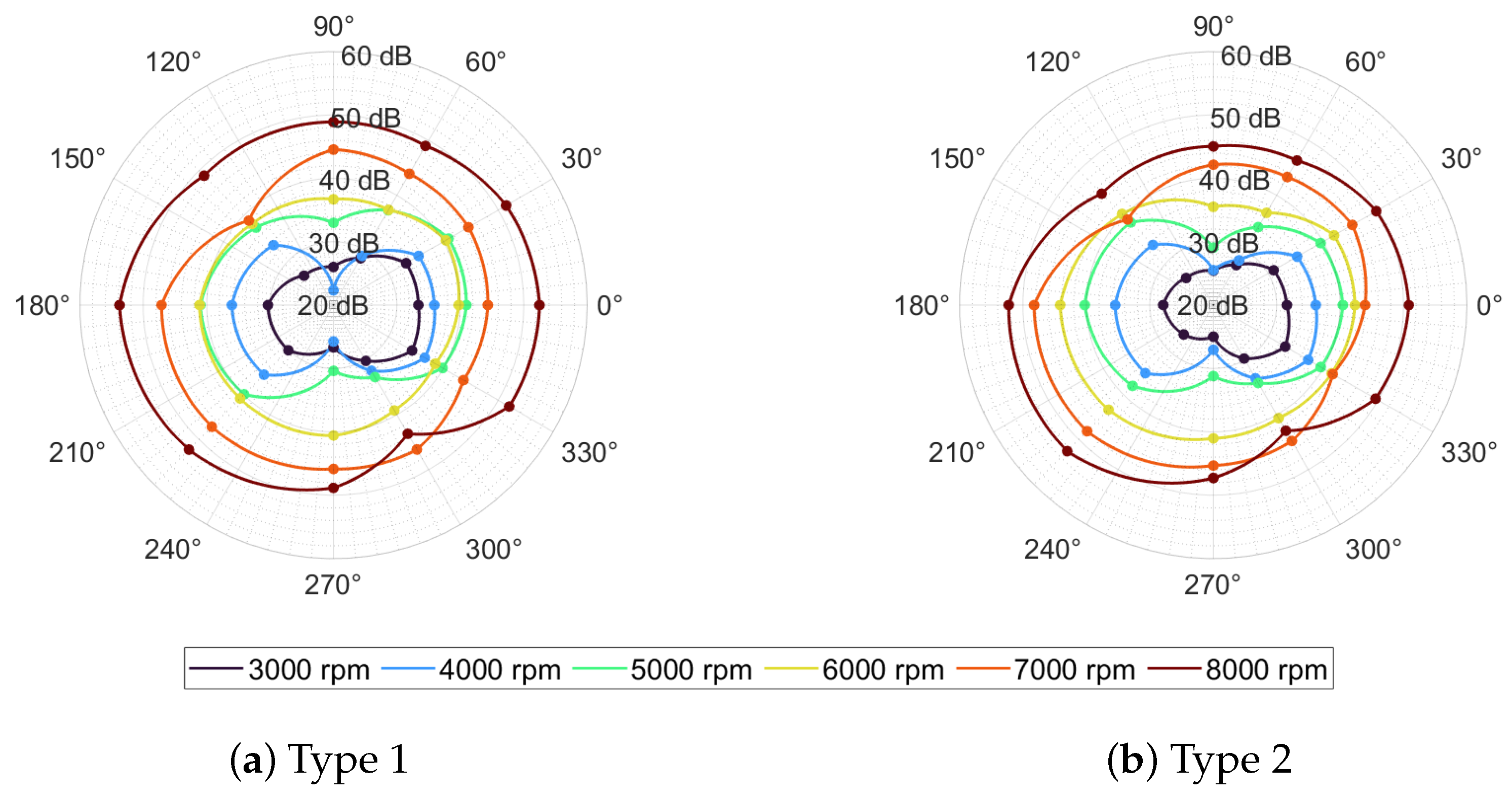
An additional analysis was carried out on the SPL evaluated exactly at the BPF harmonic for the same isolated rotor, equipped with either the Type-1 or the Type-2 propeller and operated in both CCW and CW directions. For each measurement, the peak value was extracted automatically by searching for the maximum within a ±5 Hz window centred on the theoretical harmonic frequency computed from the measured rotational speed. The fundamental BPF harmonics are then plotted as functions of azimuth, and the resulting polar diagrams for the full range of tested speeds are presented in
Figure 14 and
Figure 15.
Across the entire operating envelope, the SPL of the first BPF harmonic increases monotonically with rotational speed, rising from approximately 30 dB at 3000 rpm to 70 dB at 8000 rpm. Since the blade tip Mach number never exceeds 0.3, this growth can be attributed almost exclusively to the loading noise component [
27]. The measured directivity patterns, however, depart markedly from the ideal distribution predicted by classical isolated propeller theory. Although a local minimum persists aft of the disc, sound levels remain elevated over much of the circumference, and the dips are far less pronounced than theory anticipates. Ongoing numerical simulations of the same configuration indicate that reflections from the chamber floor redirect tonal energy into directions that should otherwise be relatively quiet, most notably at 0° and 180°. Further distortion is plausibly introduced by aerodynamic and acoustic interactions with the test rig, interference lobe formation, and other secondary effects. The absolute maxima occur near 60° and 300° and become increasingly pronounced with rising rotational speed, behaviour consistent with the growing contribution of loading noise. When the sense of rotation is fixed, the two blade sets yield almost identical polar contours, confirming measurement repeatability and implying that installation asymmetries govern the first BPF harmonic pattern. The attenuation observed at 90° at 7000 rpm is likewise attributed to combined aerodynamic and acoustic installation effects, particularly the support pylon and reflective floor. A comprehensive numerical investigation is planned to isolate these mechanisms and quantify their relative importance.
The trends broadly echo those found at the fundamental tone but with systematically lower absolute levels and a different angular signature. Between 3000 and 8000 rpm, the SPL rises from approx. 25 dB to a maximum of 50 dB. The roughly 20 dB offset relative to the first harmonic reflects the rapid roll-off with harmonic order that is predicted by theory.
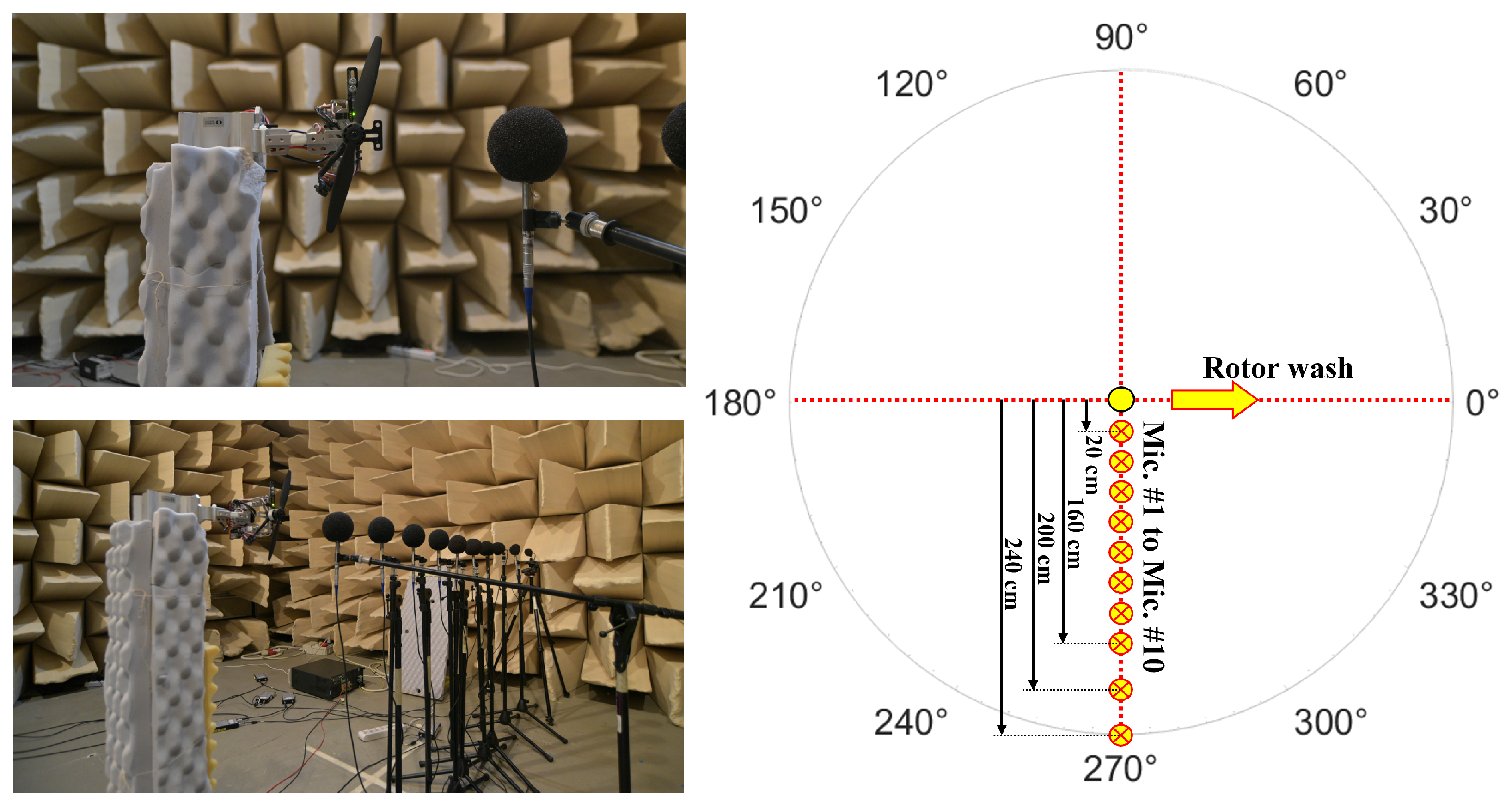
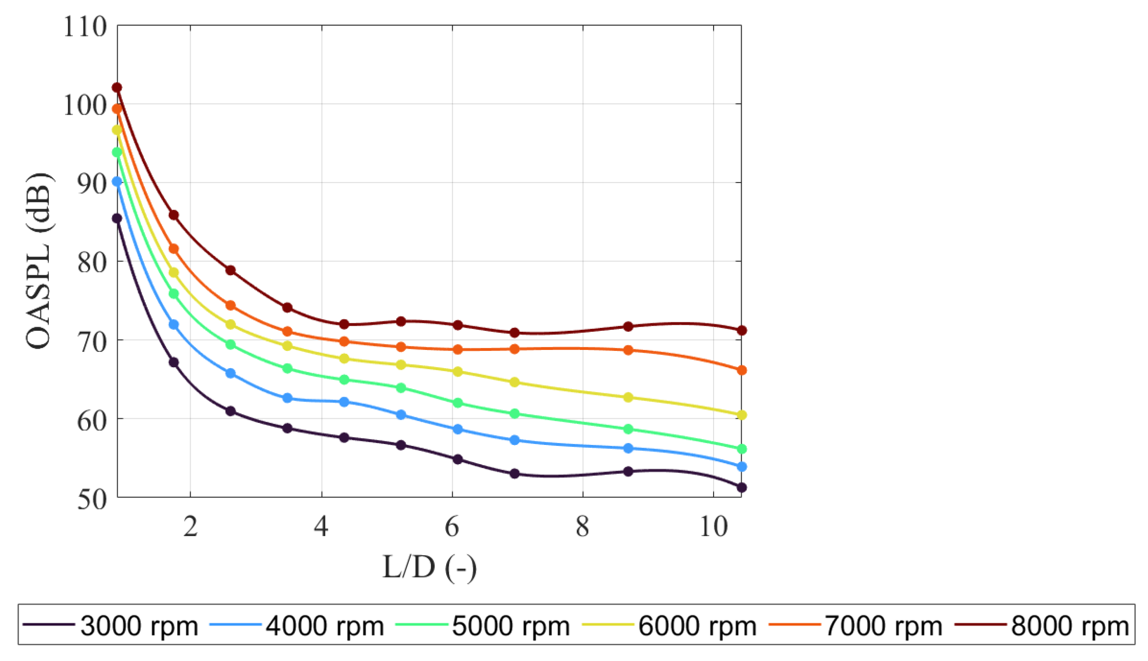
A supplementary measurement campaign was performed to determine how the acoustic signature of the isolated rotor decays with distance at various rotational speeds. In the second arrangement (
Figure 7), ten microphones were aligned in the plane of rotation, at hub height, covering the line from 90° to 270° with respect to the original array (
Figure 6). The line of sensors started in the immediate vicinity of the blade tip (<0.1 m from the tip) and ended 2.40 m from the hub, i.e., from L/D approx. 0.9 to L/D approx. 10.4. This layout captured both the near field and the far field simultaneously. At the maximum fundamental BPF (approx. 270 Hz, corresponding to 8000 rpm), the microphones, windscreens, and support stands are acoustically compact relative to the wavelength and therefore introduce negligible shadowing. The array may thus be regarded as transparent at this tone, so the measured levels accurately represent the propeller’s radiated sound. Aerodynamic interference is likewise improbable since all sensors are located in the rotor plane, and the closest element is 0.5 D from the blade tip. Although the equipment may begin to scatter energy at frequencies of several kilohertz and above, the resulting sound pressure levels are orders of magnitude lower than those at the first BPF; thus, these interferences can be confidently neglected in the OASPL analysis. The data are presented in terms of OASPL. Specifically,
Figure 18 illustrates the variation of OASPL as a function of the
ratio, where
L denotes the distance from the rotor hub to the microphone and
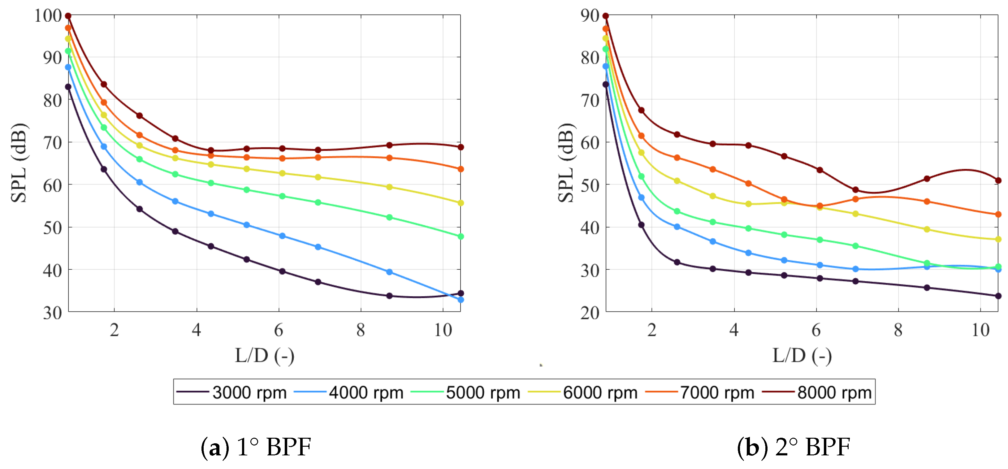
D represents the rotor diameter (230 mm). Complementary results for the tonal components are provided in
Figure 19, which plots the peak SPL of the first two BPF harmonics as functions of the same
ratio.
In proximity to the rotor tip, the OASPL ranges from approximately 85 dB at 3000 rpm to 102 dB at 8000 rpm. At a distance of
, the OASPL falls to between 51 dB and 71 dB, corresponding to a net attenuation exceeding 30 dB. Throughout the measurement domain, the vertical separation between OASPL curves for consecutive rotor speeds remains consistently in the range of 3-4 dB per 1000 rpm (mean across all locations). The decay behaviour changes with distance. For
, the level falls by about 17 dB per distance doubling, indicating that the field is still dominated by the reactive component. Beyond
, however, the measurements adhere closely to the far-field decay law, exhibiting a reduction on the order of 6 dB per distance doubling. Specifically, the observed mean attenuation across all tested rotational speeds is marginally less than 6 dB, consistent with the influence of ground reflections. Superimposed on this trend, pronounced oscillations appear, most evident at 7000 and 8000 rpm. These fluctuations originate from constructive and destructive interference between the direct acoustic wave and its ground-reflected counterpart, yielding frequency- and range-dependent local sound pressure minima and maxima [
28]. The quasi-constant OASPL observed at certain distances and frequencies is not yet understood and warrants further investigation.
For the first BPF harmonic, the SPL measured immediately adjacent to the rotor tip increases from approximately 83 dB at 3000 rpm to nearly 100 dB at 8000 rpm. Moving downstream, the level falls off sharply: at approx. , it reaches about 34 dB at 3000 rpm and 69 dB at 8000 rpm, corresponding to overall attenuations of roughly 49 dB and 31 dB, respectively. At any fixed , a 1000 rpm increase in speed raises the first BPF level between 3 and 8 dB. In the near field (), the decay rate is steep, approximately 17 dB per doubling of distance. Beyond roughly , however, the decay relaxes to nearly the far-field value of 6 dB per doubling, although slightly elevated (between 6 and 8 dB). Superimposed on this smooth roll-off are ripples and occasional plateaus, mirroring those seen in the OASPL. The second harmonic exhibits the same overall trends, with lower absolute levels. Near the propeller, the second BPF SPL ranges from about 74 dB at 3000 rpm up to 90 dB at 8000 rpm. At , it has dropped to approximately 24 dB and 51 dB. Each 1000 rpm produces between a 4 and 6 dB increase in the level. The levels decay from roughly 28 dB per doubling in the near field to about 6 dB per doubling in the far field, and the same interferences appear, especially at higher speeds.
3.2.2. Comparison of Isolated, Plate-Mounted, and Quadcopter Rotor Configurations
To investigate the influence of the mounting structure on rotor acoustics and to examine how acoustic waves interact with a supporting plate, a single rotor was first mounted on an aluminium plate that replicates the mounting surface of the
Intel Aero Ready-to-Fly Drone. The arrangement is shown in
Figure 20, which provides a photograph of the full quadcopter. Only the plate and the operative rotor (highlighted by the red circle) were used in the present tests. In this setup, the rotor is positioned at the bottom-right corner of the plate, whereas the microphones are aligned with the plate’s geometric centre, thereby establishing a symmetric test rig in contrast with the asymmetric isolated rotor configuration described earlier. All tests were conducted at the same rotational speeds as before. For comparison, a second configuration employed the quadcopter, with all four rotors mounted on the same aluminium plate (
Figure 20) and driven at the same shaft speeds for each of the rpm settings investigated, except at the top setting, where the drive system imposed a ceiling limit of 7900 rpm instead of the targeted 8000 rpm. In practice, however, the four propellers were not phase-locked, and their instantaneous rotational speeds differed slightly. Over the 30 s acquisition window, the relative phase relationships therefore swept through many values, so the measured spectrum represents a time average over all phase alignments.
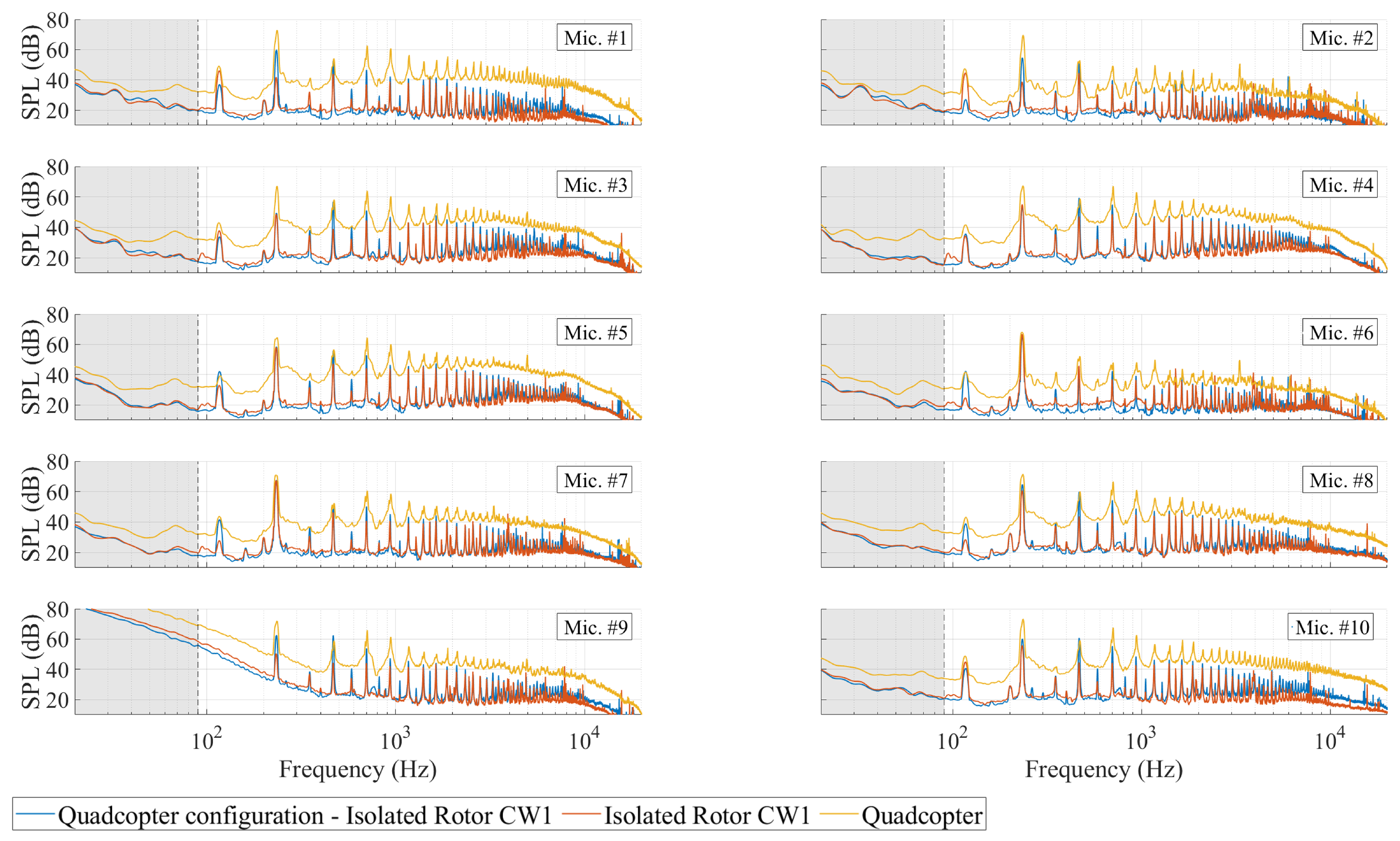
Figure 21 presents the unweighted SPL spectra measured by ten-microphones distributed over the full 360° azimuth for the three analysed configurations at 7000 rpm. The first configuration features an isolated two-blade rotor, represented by the orange curve. The second configuration involves the same rotor mounted on an aluminium plate in a quadcopter geometry, depicted in blue. Finally, the entire quadcopter assembly, comprising all four rotors and their supporting structure, is shown in yellow.
In all cases, BPF harmonics appear at their expected theoretical positions; however, their sharpness and the surrounding broadband level vary with the extent of aerodynamic and acoustic interaction. In the quadcopter configuration, the elevated low-frequency levels recorded by microphone 9, similar to those observed in the isolated rotor tests, can be attributed to wake-induced turbulence. The BPF harmonics do not manifest as the sharp spectral lines characteristic of a single propeller; instead, they coalesce into broadened clusters. This broadening occurs since the four rotors operate at slightly different speeds, and the subsequent Welch method averaging causes the individual peaks to merge. These harmonics remain observable into the mid-frequency band, although with diminished amplitude, while above a few kilohertz the spectrum exhibits a gradual roll-off accompanied by elevated broadband energy, reflecting additional noise generated by rotor–rotor wake interactions and airframe-induced turbulence. When the rotor is tested in complete isolation, each BPF harmonic is sharply resolved beyond 10 kHz, and the broadband component remains low, confirming the absence of reflective or interacting surfaces. Mounting the same rotor on the support plate yields an intermediate response; specifically, the BPF harmonics generally intensify relative to the isolated case, and the broadband level increases from about 2 kHz upward, effects that can be ascribed to interaction with the plate. While microphones near the rotor plane consistently exhibit a reduction in broadband energy up to roughly 1–2 kHz.
For completeness,
Figure 22 presents the narrowband SPL spectra measured for both the propeller-equipped rotors and the unloaded motors, each running at approximately 7000 rpm with all four rotors in operation. In the unloaded motors configuration, the acoustic signature is characterised by a modest broadband hump across the mid-frequency band, punctuated by discrete tonal components. Notably, at frequencies such as 117 Hz, the motors alone constitute the dominant source of SPL. Upon installation of the propellers, a pronounced series of tonal peaks emerges, the first of which corresponds to the BPF of roughly 234 Hz (two-blade propeller at 7000 rpm). These sharp harmonics are superimposed upon a substantially elevated broadband background, resulting in an overall increase of about 20–40 dB relative to the motor alone.
Previous investigations have shown that, in enclosed facilities, re-ingestion of the propeller wake can increase both tonal and broadband noise radiation [
29,
30,
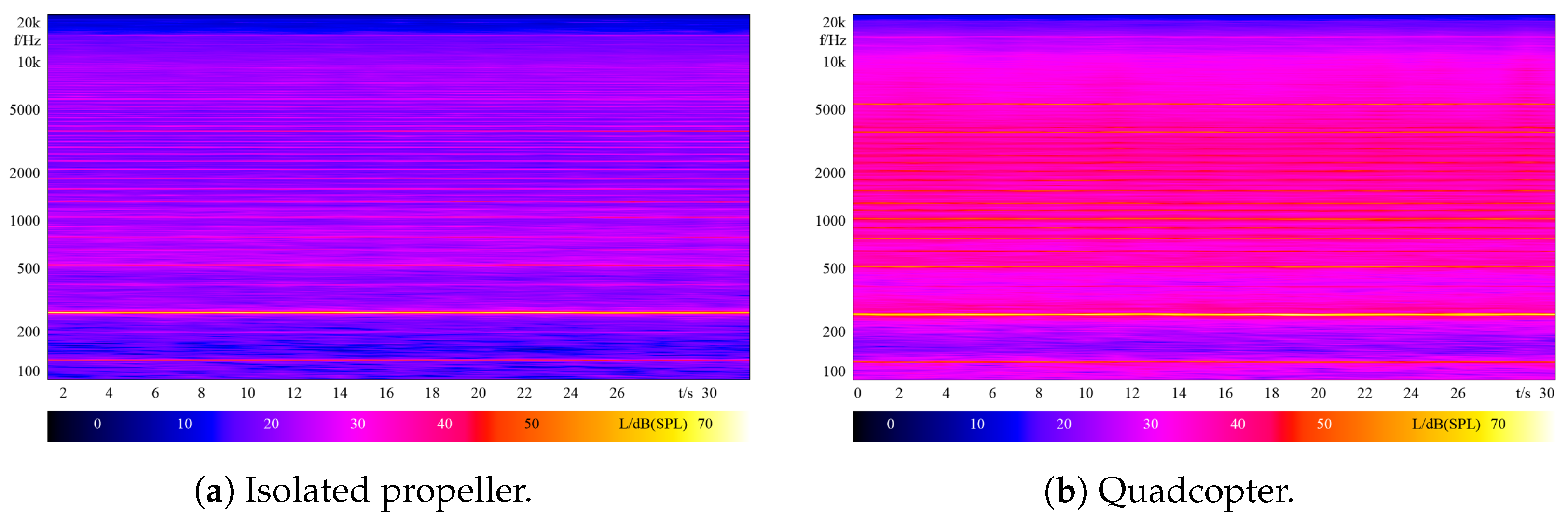
31]. To assess whether this mechanism could bias the present measurements,
Figure 23 reports spectrograms recorded with microphone 2 for the isolated propeller and quadcopter configurations operating at their respective maximum rotational speeds (8000 rpm and 7900 rpm). In both cases, the BPF harmonics remain sharp and strictly horizontal for the entire 30 s record, and no progressive rise in broadband energy is detected. These observations rule out significant wake recirculation, a conclusion that is consistent with the test setup. The rotor plane is situated approximately 6 D above the floor and directs its flow parallel to it, while the nearest wall along the wake axis lies more than 12 D downstream. Under such clearances, the wake cannot close a recirculation loop before dispersing, and any associated acoustic contribution is therefore deemed negligible.
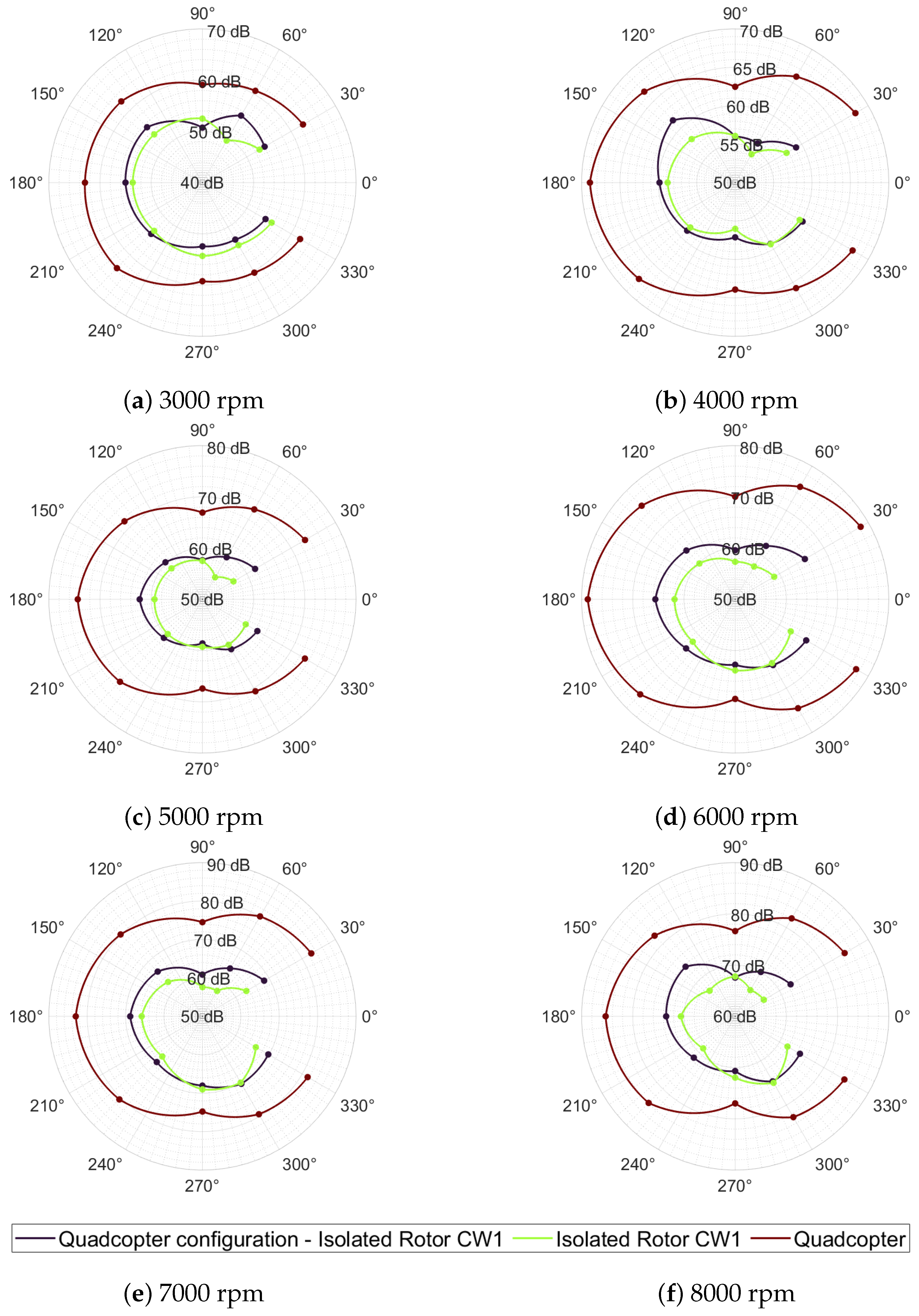
A more in-depth comparison is provided in
Figure 24, which displays the OASPL measured over the full 360° azimuth for the configuration defined as setup #1 in
Figure 6.
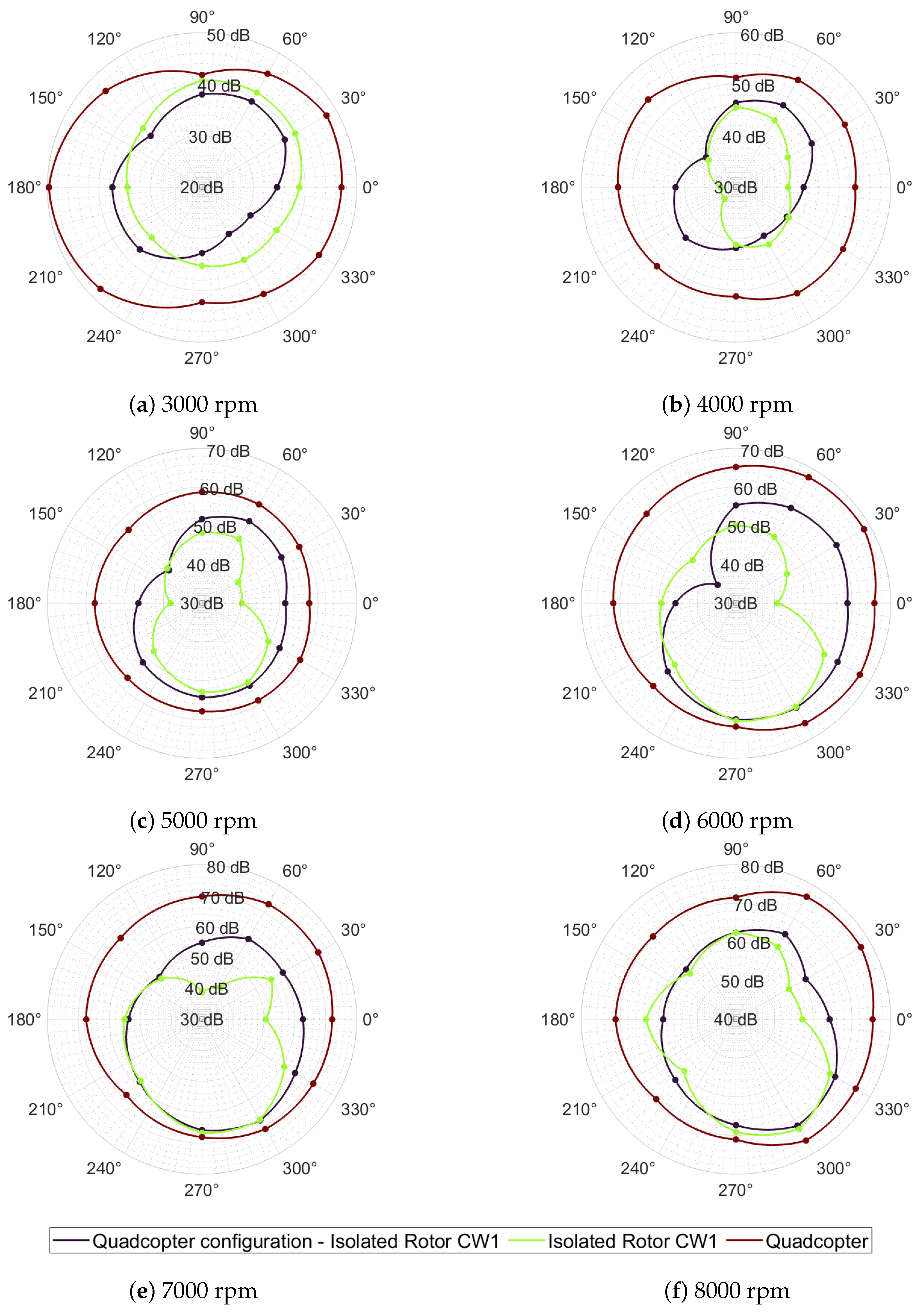
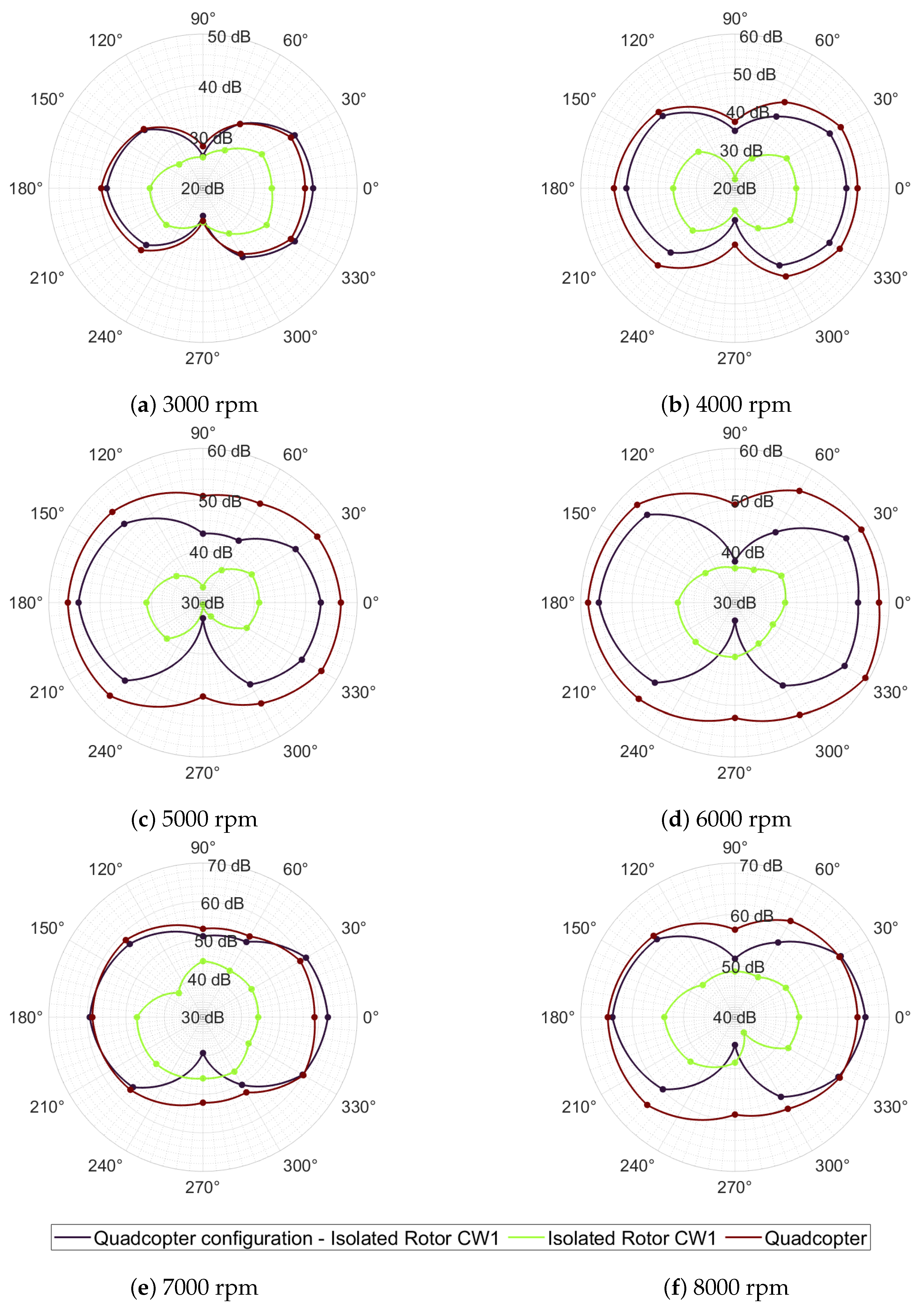
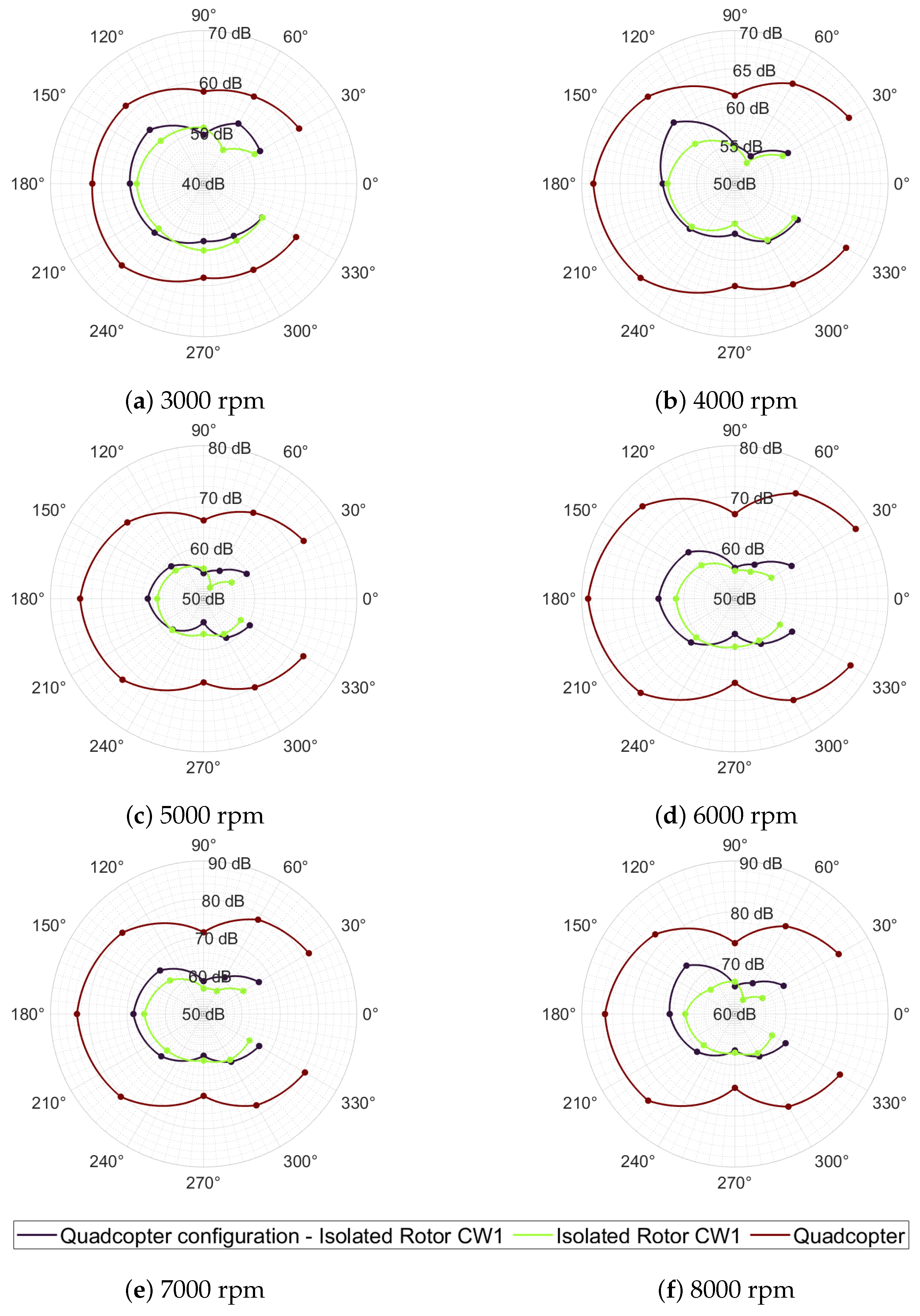
Figure 25 and
Figure 26 show the corresponding directivity patterns at the first and second BPF harmonics, respectively. The isolated rotor is plotted in dark purple, the same rotor mounted on the aluminium plate in green, and the quadcopter in brown. In each case, the downwash axis is defined at 0°. Measurements taken within the 0°–90° sector will not be analysed in order to avoid any potential misunderstandings that may arise from additional interference from the pylon, as observed during the isolated rotor test.
Analysis of the polar directivity patterns for the single rotor mounted on the aluminium plate reveals a pronounced left (0°–180°) versus right (180°–360°) asymmetry in both the OASPL and the first two BPF harmonics, with the effect most marked at the fundamental tone. Although the microphone array is symmetrically arranged relative to the test rig, the rotor’s off-centre placement in the lower-right quadrant of the plate induces a directional bias. The largest deviation between mirrored microphones occurs consistently between the 60° and 330° positions, observed in both the OASPL and first BPF harmonic, a consequence of partial acoustic shielding by the plate edge and the misalignment of the rotor axis relative to the array centre. In particular, microphones at 210°–330° lie closer to the rotor than those at 30°–150°, amplifying the observed imbalance. The first harmonic of the BPF contour displays the strongest anisotropy, with a mean level difference of roughly 6.5 dB between mirrored left- and right-side microphones. At first glance, one might attribute this trough to simple geometric shadowing and/or the unequal distances between the off-centre rotor axis and the microphones. However, the 266.7 Hz tone observed at 8000 rpm corresponds to an acoustic wavelength of roughly 1.3 m, over three times the 0.36 m plate span, rendering classical blockage effects insufficient to account for the measured anisotropy. Likewise, under a far-field decay assumption, the minor path length difference would contribute only about 1.6 dB. Instead, the pronounced asymmetry may arise from near-field interactions, in which the rotor’s pressure field couples with the plate edge and ground surface, producing direction-dependent interference among direct, reflected, and scattered acoustic components and thus yielding the observed directivity pattern. By contrast, at the second BPF harmonic, the behaviour reverses. Only minor left-right asymmetries are observed, likely owing to slight differences in the radial distances of mirrored microphones from the rotor axis. Nonetheless, a large local discrepancy, approximately 10 dB between mirrored microphones, was observed within the rotor plane. When the entire spectrum is integrated to yield the OASPL, the fundamental’s left-right disparity is partially compensated by mid- to high-frequency scattered energy, reducing the mean level difference between mirrored microphones to approximately 2.3 dB.
The quadcopter OASPL patterns exhibit instead a dipole-like distribution at all speeds, gradually evolving into a slightly oblate shape as rpm increases, with elevated levels towards the wake (±30°) and minima along the rotor plane (90°and 270°). The OASPL rises steadily from approximately 60 dB at 3000 rpm to over 85 dB at 7900 rpm. At low rotational speeds, the first BPF harmonic also exhibits a dipole-like directivity, but as the rotor speed increases, its minimum shifts forward of the rotor plane, producing an oblate monopole pattern with enhanced radiation into the wake. Across the full 360° azimuth, its SPL variation remains below 9 dB. This behaviour, similar to that observed for the isolated propeller, likely arises from ground reflections that become more energetic as rotor loading grows, thereby smoothing the angular distribution at high rpm. By contrast, the second BPF harmonic maintains a pronounced dipole directivity, although at lower absolute levels, and progressively evolves towards a more omnidirectional pattern as rotor speed increases.
Compared with the isolated rotor case, the acoustic directivity of the single propeller changes markedly when it is mounted on the aluminium plate. In particular, OASPL measured at the frontal azimuth (approximately 180°) increases by 1.0–3.5 dB (mean +2.5 dB) relative to the isolated rotor baseline. A more pronounced enhancement of 1.5–6.5 dB (mean +3.5 dB) occurs near 135°, consistent with sound wave reflections from the plate, given the rotor’s offset position. Additional increases of approximately 2 dB are observed around 330° (and at 30°, although the latter cannot be unambiguously ascribed to the plate). Conversely, mounting the rotor on the plate produces acoustic shadows in the propeller plane, yielding a mean reduction of about 1 dB at 270°. In summary, installation on the aluminium plate amplifies axial emission lobes while introducing lateral acoustic shadowing. At the fundamental BPF, the directivity pattern exhibits two prominent maxima, specifically, a mean enhancement of roughly 4 dB centred at an azimuth of 225° and an average increase of about 8 dB within the wake sector. At the second harmonic, the acoustic field generated by a single rotor mounted on the plate assumes a dipole-like directivity that mirrors the quadrotor pattern, indicating that the mounting plate principally governs the second BPF radiation. Absolute levels are substantially higher than those of the isolated rotor and approach those measured for the quadcopter. This, introducing the remaining three rotors, only modestly amplifies this dipole, with the largest deviations confined to the rotor plane.
Finally, to quantify the perceptually relevant acoustic changes induced by this plate interaction,
Figure 27 presents the A-weighted OASPL polar patterns for the same three configurations across rotor speeds from 3000 rpm to 8000 rpm. By applying the A-weighting filter, which reduces the contributions of very low and very high frequencies in a manner roughly corresponding to the human ear’s sensitivity, these plots reveal how spectral reshaping influences the apparent loudness and directivity of the rotor noise.
On average across all tested rotational speeds, the A-weighted directivity of the plate-mounted propeller exceeds that of the isolated propeller configuration, with the sole exception of the rotor plane direction. In this orientation, the addition of the plate induces a slight reduction in A-weighted levels. Therefore, for equivalent acoustic source power, the presence of the plate generally elevates the perceived annoyance of the noise, except within the rotor plane, where the plate-mounted configuration resulted inm marginally quieter noise.


